an introduction to the 2d testbed - cg:p&p
TRANSCRIPT

An introduction to the 2D testbed
CGPP already introduced you to the 2D testbed at some level. This article is about doing the real stuff – actually building a new program atop the testbed. Let’s start from scratch, and assume that you’ve downloaded a zip file from the website, and have unzipped it. I’m going to assume that it’s in the location
C:\BOOK\BookCode\GraphicsBook\GraphicsBook\
because that’s where it is on my computer. The only point I need to make about this is that you really, really, really want this to be installed on a local disk, not a network drive. On a network drive, there are subtle permissions problems that may make it impossible to run your programs, and the error messages telling you this will be cryptic at best.
Before you can do anything else, you’ll need a copy of Visual Studio as well. Install that on your machine, and then follow the instructions at
http://msdn.microsoft.com/en-us/library/ms752299.aspx to confirm that you can actually build and run a WPF project in Visual Studio as you’ve installed it. Once you’re past that hurdle, we can move on.
The folder you’ve gotten by unzipping the zip file will look something like this:
although some of those subfolders won’t be shipped with the software – they’re just ones that I built while writing the book. Indeed, some are solutions to exercises in the book. The little green checkmark icons are an overlay that tell me I’ve saved a copy of this file; you probably won’t see those, or the CVS file, which is also associated with that backup process.
Let’s start with a very practical problem: write a program that lets the user click on three points, and then draws the circle that passes through those three points. If the three points are collinear, then “circle” has to be replaced by “line”. We’ll be working in a portion of the plane that ranges from -100 to 100 in each coordinate, and in practice, we’ll work around this special case (exact collinearity) by perturbing one of the points a tiny bit; that’ll change the line into a circle of huge radius, but within our 200 x 200 window, the difference will not be noticeable.
Let’s make our task a little simpler: our program will start with three dots and let the user drag them around. That’ll simplify the program logic a little, saving us from having to ask, “How many points have been clicked so far?” and, “Has the reset button been pressed?”
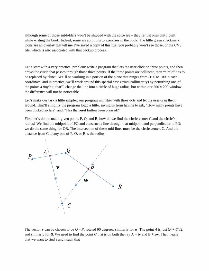
First, let’s do the math: given points P, Q, and R, how do we find the circle-center C and the circle’s radius? We find the midpoint of PQ and construct a line through that midpoint and perpendicular to PQ; we do the same thing for QR. The intersection of these mid-lines must be the circle center, C. And the distance from C to any one of P, Q, or R is the radius.
The vector v can be chosen to be Q – P, rotated 90 degrees; similarly for w. The point A is just (P + Q)/2, and similarly for B. We need to find the point C that is on both the ray A + tv and B + sw. That means that we want to find s and t such that
𝑃 𝑄
𝑅
𝐴
𝐵 v
w
𝐶
A + tv = B + sw or
tv - sw = B - A
We can rewrite this as a matrix equation:
[v; w][t; -s]t = B – A = (P + Q)/2 – (Q + R)/2 = (P – R)/2,
where [v; w] means “the matrix whose columns are v and w. That means we’ve got an equation of the form Ax = b.
That’s easy to solve. Furthermore, if the determinant of [v; w] is too small compared to the lengths of v and w, we’re in the “huge circle” situation. We can simplify things slightly by normalizing v and w when we compute them; then the determinant alone suffices to tell us when we’re in the “big circle” situation.
Anyhow, once the user has clicked on 3 points, we’ll do the computations above and draw a circle. But we’ve got a ways to go before we get there.
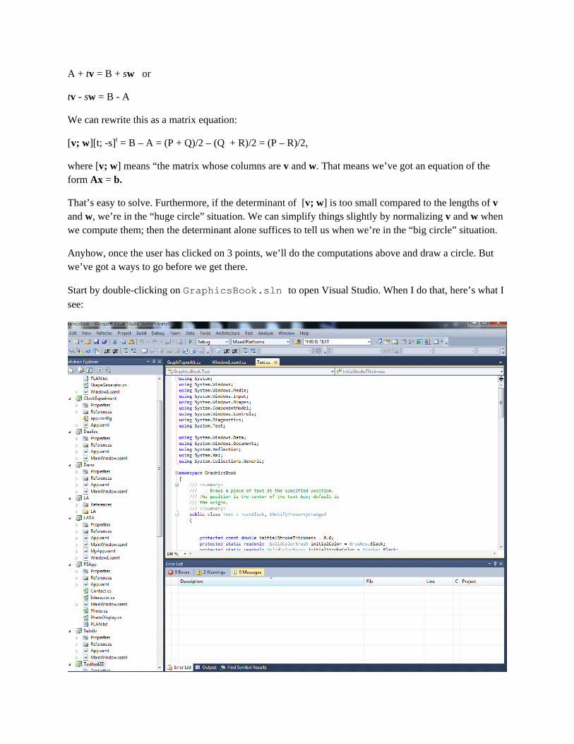
Start by double-clicking on GraphicsBook.sln to open Visual Studio. When I do that, here’s what I see:
Visual studio organizes related items in a “solution,” and the individual parts are called “projects.” You can see that within my version of the solution, there are projects called Dualize and Durer, and lower down, Testbed2D, which is the library that supports all the others. (The other library is LA, which has some linear algebra functionality.)
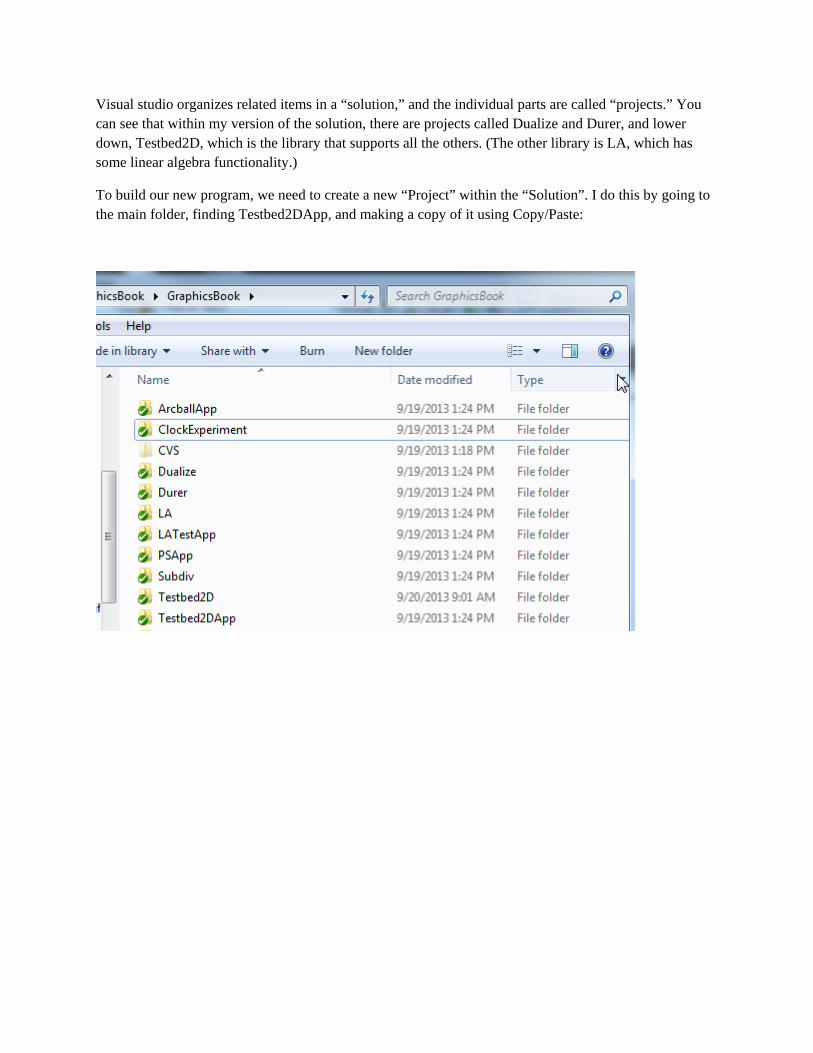
To build our new program, we need to create a new “Project” within the “Solution”. I do this by going to the main folder, finding Testbed2DApp, and making a copy of it using Copy/Paste:
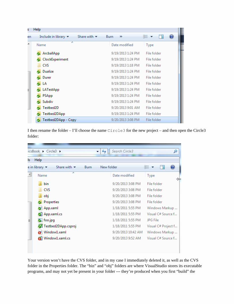
I then rename the folder – I’ll choose the name Circle3 for the new project – and then open the Circle3 folder:
Your version won’t have the CVS folder, and in my case I immediately deleted it, as well as the CVS folder in the Properties folder. The “bin” and “obj” folders are where VisualStudio stores its executable programs, and may not yet be present in your folder --- they’re produced when you first “build” the
solution in Visual Studio (which I’ll call VS from now on). The “Properties” folder is where VS stores various settings for the project. The xaml and cs files are the things we’ll actually work with. And foo.jpg is a photo that’s used in the testbed app, and which we’ll remove soon. And finally, we should change the name from Testbed2DApp.csproj to Circle3.proj.
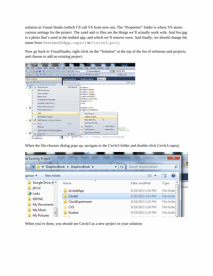
Now go back to VisualStudio, right-click on the “Solution” at the top of the list of solutions and projects, and choose to add an existing project:
When the file-chooser dialog pops up, navigate to the Circle3 folder and double-click Circle3.csproj:
When you’re done, you should see Circle3 as a new project in your solution:
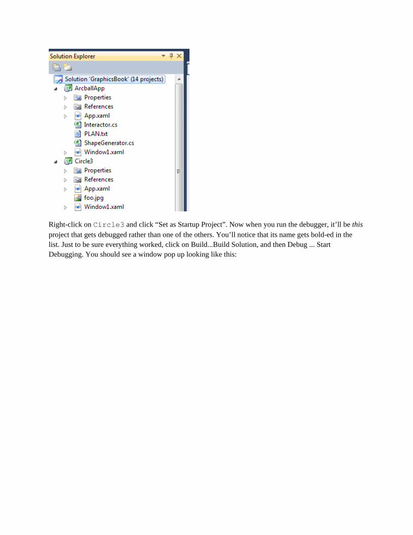
Right-click on Circle3 and click “Set as Startup Project”. Now when you run the debugger, it’ll be this project that gets debugged rather than one of the others. You’ll notice that its name gets bold-ed in the list. Just to be sure everything worked, click on Build...Build Solution, and then Debug ... Start Debugging. You should see a window pop up looking like this:

We’re now going to remove almost everything that generated all that visual content (except for the axes and graph-paper, which are the standard background). Click File...Exit and click “Yes” in response to the “Really Exit?” question. You’ll be returned to VS.
The large-scale structure of the program (which you’ll never need to care about) is that there’s an App.xaml/cs pair which basically tells WPF that this is an Application, and that it should provide
certain basic things for it, like a “File” menu. Within that context, it says that the initial WPF object to display is a Window1, highlighted here in the code for App.xaml:
<Application x:Class="GraphicsBook.App" xmlns="http://schemas.microsoft.com/winfx/2006/xaml/presentation" xmlns:x="http://schemas.microsoft.com/winfx/2006/xaml" StartupUri="Window1.xaml"> <Application.Resources> </Application.Resources> </Application> The associated C# file does nothing at all except to declare that our App class is derived from the WPF class Application.
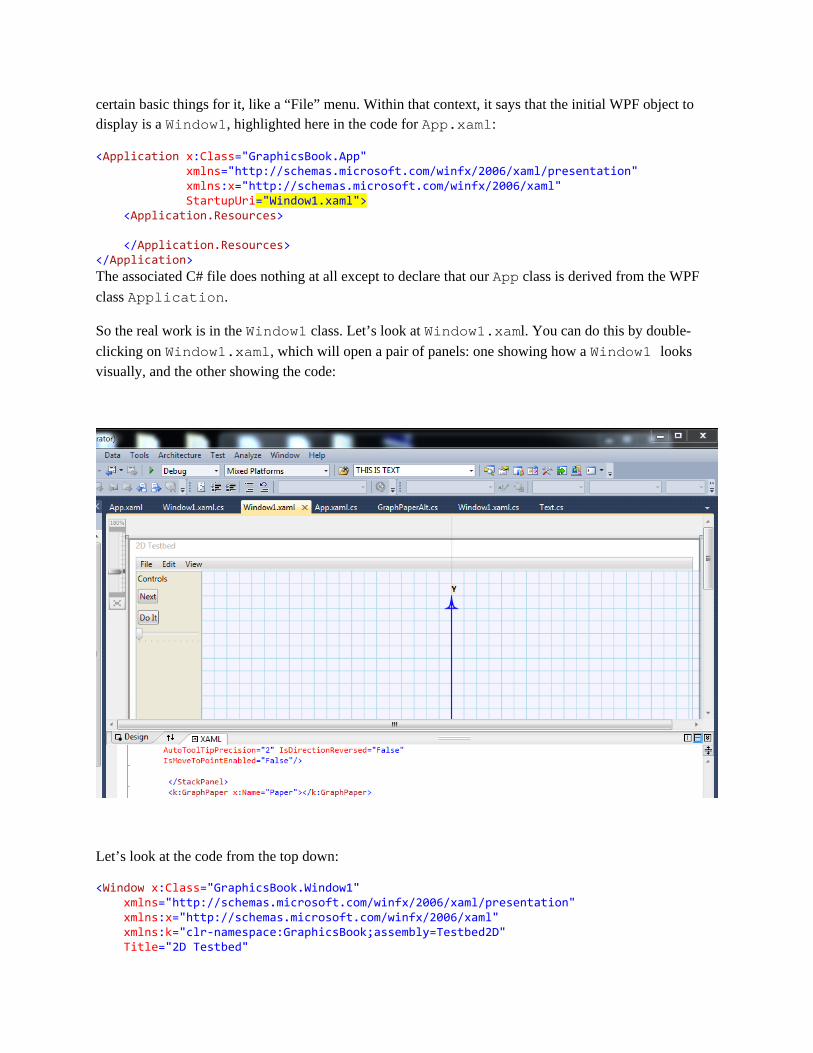
So the real work is in the Window1 class. Let’s look at Window1.xaml. You can do this by double-clicking on Window1.xaml, which will open a pair of panels: one showing how a Window1 looks visually, and the other showing the code:
Let’s look at the code from the top down:
<Window x:Class="GraphicsBook.Window1" xmlns="http://schemas.microsoft.com/winfx/2006/xaml/presentation" xmlns:x="http://schemas.microsoft.com/winfx/2006/xaml" xmlns:k="clr-namespace:GraphicsBook;assembly=Testbed2D" Title="2D Testbed"

OK. The first line says that we want a window whose class is “GraphicsBook.Window1”. The next says that the xml namespace in which we’re making this window is the XAML/presentation namespace, i.e., the one in which all the XAML objects are already known.
Next we say that the letter “x” can be used as a prefix in referring to XAML objects, and the letter “k” can be used in referring to the objects in the GraphicsBook solution, within the Testbed2D project. These will be things like “Arrow” and “Dot” that made up the visual content of the window that you saw when you ran the program.
Finally, we say that the window title should be “2D Testbed”. Change that to be “3-point circle”, and you should see the title (in grey, at the upper left) change to “3-point circle.”
The next few lines are
KeyDown="KeyDownHandler" Height="810" Width="865" > The first declares that any key-press that occurs in this window should result in an invocation of the procedure KeyDownHandler (which is in a C# file). The next two specify the width and height of the window in pixels.
The next bit of code
<DockPanel LastChildFill="True"> <Menu DockPanel.Dock="Top"> <MenuItem Header="_File"> ... </MenuItem> <MenuItem Header="Edit"/> <MenuItem Header="View"/> </Menu> <StackPanel x:Name="stack" DockPanel.Dock ="Left" Orientation="Vertical" ...> ... </StackPanel> <k:GraphPaper x:Name="Paper"></k:GraphPaper> describes the broad structure: the window is filled by a DockPanel (first line) with three children – a menu bar (next several lines), a StackPanel, and a GraphPaper. You can see for yourself that several of the menubar items are bound to procedures like “ApplicationCommands.Open”; the Exit item also allows you to type Ctrl-X to exit. The StackPanel contains the UI Controls – things like buttons, text, and sliders. We don’t need most of these for our project. Let’s alter the first one (the “TextBlock”), to say something helpful: <StackPanel x:Name="stack" DockPanel.Dock ="Left" ...> <TextBlock Margin="3" Text=" Click and drag any dot to reshape circle. "/> and then change the button labels and the “Click handlers” as well: <Button Margin="3,5" HorizontalAlignment="Left"
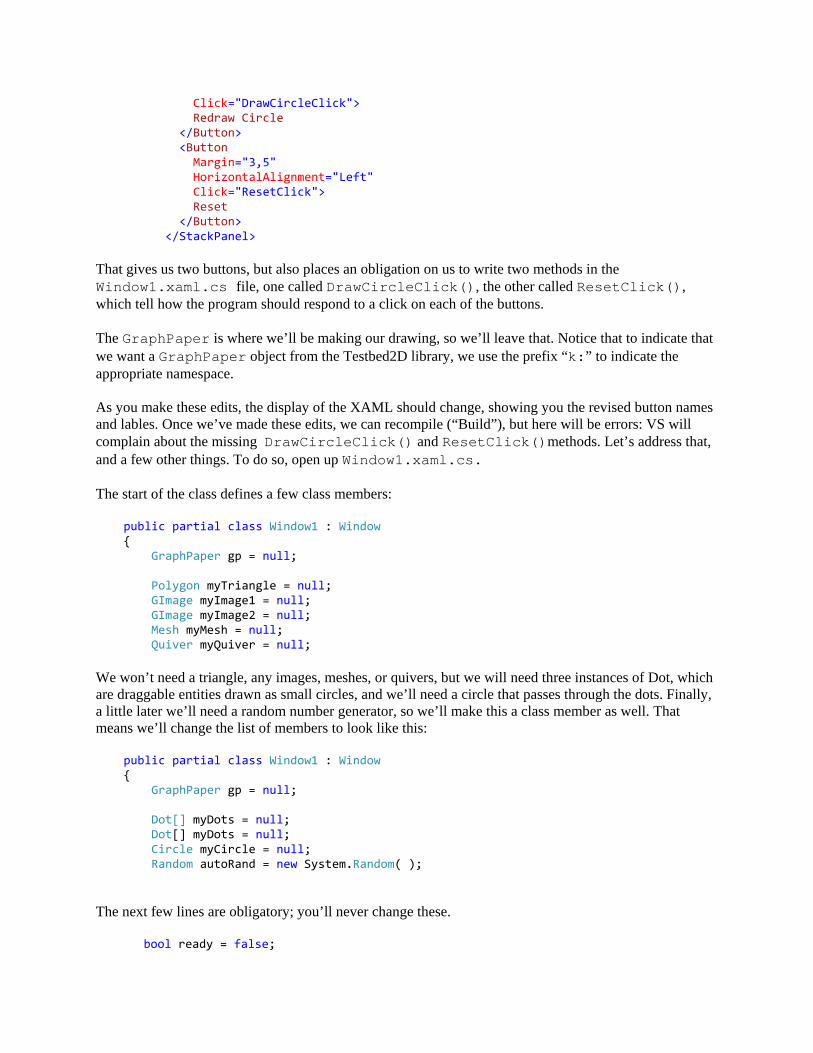
Click="DrawCircleClick"> Redraw Circle </Button> <Button Margin="3,5" HorizontalAlignment="Left" Click="ResetClick"> Reset </Button> </StackPanel> That gives us two buttons, but also places an obligation on us to write two methods in the Window1.xaml.cs file, one called DrawCircleClick(), the other called ResetClick(), which tell how the program should respond to a click on each of the buttons. The GraphPaper is where we’ll be making our drawing, so we’ll leave that. Notice that to indicate that we want a GraphPaper object from the Testbed2D library, we use the prefix “k:” to indicate the appropriate namespace. As you make these edits, the display of the XAML should change, showing you the revised button names and lables. Once we’ve made these edits, we can recompile (“Build”), but here will be errors: VS will complain about the missing DrawCircleClick() and ResetClick()methods. Let’s address that, and a few other things. To do so, open up Window1.xaml.cs. The start of the class defines a few class members: public partial class Window1 : Window { GraphPaper gp = null; Polygon myTriangle = null; GImage myImage1 = null; GImage myImage2 = null; Mesh myMesh = null; Quiver myQuiver = null; We won’t need a triangle, any images, meshes, or quivers, but we will need three instances of Dot, which are draggable entities drawn as small circles, and we’ll need a circle that passes through the dots. Finally, a little later we’ll need a random number generator, so we’ll make this a class member as well. That means we’ll change the list of members to look like this: public partial class Window1 : Window { GraphPaper gp = null; Dot[] myDots = null; Dot[] myDots = null; Circle myCircle = null; Random autoRand = new System.Random( ); The next few lines are obligatory; you’ll never change these.
bool ready = false;
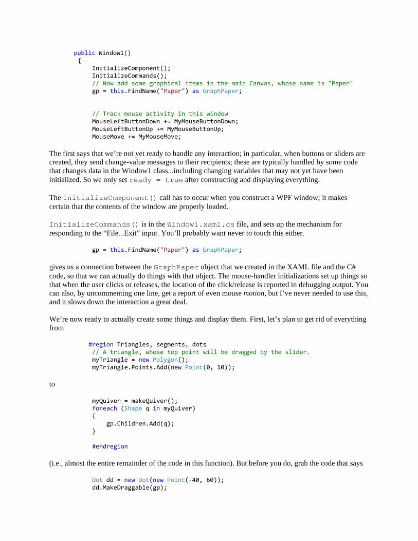
public Window1() { InitializeComponent(); InitializeCommands(); // Now add some graphical items in the main Canvas, whose name is "Paper" gp = this.FindName("Paper") as GraphPaper; // Track mouse activity in this window MouseLeftButtonDown += MyMouseButtonDown; MouseLeftButtonUp += MyMouseButtonUp; MouseMove += MyMouseMove; The first says that we’re not yet ready to handle any interaction; in particular, when buttons or sliders are created, they send change-value messages to their recipients; these are typically handled by some code that changes data in the Window1 class...including changing variables that may not yet have been initialized. So we only set ready = true after constructing and displaying everything. The InitializeComponent() call has to occur when you construct a WPF window; it makes certain that the contents of the window are properly loaded. InitializeCommands() is in the Window1.xaml.cs file, and sets up the mechanism for responding to the “File...Exit” input. You’ll probably want never to touch this either. gp = this.FindName("Paper") as GraphPaper; gives us a connection between the GraphPaper object that we created in the XAML file and the C# code, so that we can actually do things with that object. The mouse-handler initializations set up things so that when the user clicks or releases, the location of the click/release is reported in debugging output. You can also, by uncommenting one line, get a report of even mouse motion, but I’ve never needed to use this, and it slows down the interaction a great deal. We’re now ready to actually create some things and display them. First, let’s plan to get rid of everything from #region Triangles, segments, dots // A triangle, whose top point will be dragged by the slider. myTriangle = new Polygon(); myTriangle.Points.Add(new Point(0, 10)); to myQuiver = makeQuiver(); foreach (Shape q in myQuiver) { gp.Children.Add(q); } #endregion (i.e., almost the entire remainder of the code in this function). But before you do, grab the code that says Dot dd = new Dot(new Point(-40, 60)); dd.MakeDraggable(gp);
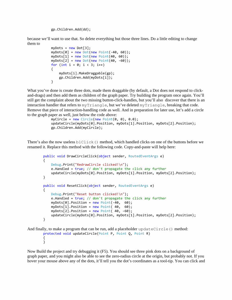
gp.Children.Add(dd); because we’ll want to use that. So delete everything but those three lines. Do a little editing to change them to myDots = new Dot[3]; myDots[0] = new Dot(new Point(-40, 60)); myDots[1] = new Dot(new Point(40, 60)); myDots[2] = new Dot(new Point(40, -60)); for (int i = 0; i < 3; i++) { myDots[i].MakeDraggable(gp); gp.Children.Add(myDots[i]); } What you’ve done is create three dots, made them draggable (by default, a Dot does not respond to click-and-drags) and then add them as children of the graph paper. Try building the program once again. You’ll still get the complaint about the two missing button-click-handles, but you’ll also discover that there is an interaction handler that refers to myTriangle, but we’ve deleted myTriangle, breaking that code. Remove that piece of interaction-handling code as well. And in preparation for later use, let’s add a circle to the graph paper as well, just below the code above: myCircle = new Circle(new Point(0, 0), 0.0); updateCircle(myDots[0].Position, myDots[1].Position, myDots[2].Position); gp.Children.Add(myCircle); There’s also the now useless b1Click() method, which handled clicks on one of the buttons before we renamed it. Replace this method with the following code. Copy-and-paste will help here: public void DrawCircleClick(object sender, RoutedEventArgs e) { Debug.Print("RedrawCircle clicked!\n"); e.Handled = true; // don't propagate the click any further updateCircle(myDots[0].Position, myDots[1].Position, myDots[2].Position); } public void ResetClick(object sender, RoutedEventArgs e) { Debug.Print("Reset button clicked!\n"); e.Handled = true; // don't propagate the click any further myDots[0].Position = new Point(-40, 60); myDots[1].Position = new Point( 40, 60); myDots[2].Position = new Point( 40, -60); updateCircle(myDots[0].Position, myDots[1].Position, myDots[2].Position); } And finally, to make a program that can be run, add a placeholder updateCircle() method: protected void updateCircle(Point P, Point Q, Point R) { } Now Build the project and try debugging it (F5). You should see three pink dots on a background of graph paper, and you might also be able to see the zero-radius circle at the origin, but probably not. If you hover your mouse above any of the dots, it’ll tell you the dot’s coordinates as a tool-tip. You can click and
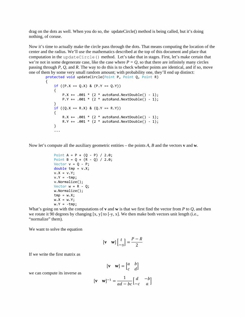
drag on the dots as well. When you do so, the updateCircle() method is being called, but it’s doing nothing, of coruse. Now it’s time to actually make the circle pass through the dots. That means computing the location of the center and the radius. We’ll use the mathematics described at the top of this document and place that computation in the updateCircle() method. Let’s take that in stages. First, let’s make certain that we’re not in some degenerate case, like the case where P = Q, so that there are infinitely many circles passing through P, Q, and R. The way to do this is to check whether points are identical, and if so, move one of them by some very small random amount; with probability one, they’ll end up distinct: protected void updateCircle(Point P, Point Q, Point R) { if ((P.X == Q.X) & (P.Y == Q.Y)) { P.X += .001 * (2 * autoRand.NextDouble() - 1); P.Y += .001 * (2 * autoRand.NextDouble() - 1); } if ((Q.X == R.X) & (Q.Y == R.Y)) { R.X += .001 * (2 * autoRand.NextDouble() - 1); R.Y += .001 * (2 * autoRand.NextDouble() - 1); } ... Now let’s compute all the auxiliary geometric entities – the points A, B and the vectors v and w. Point A = P + (Q - P) / 2.0; Point B = Q + (R - Q) / 2.0; Vector v = Q - P; double tmp = v.X; v.X = v.Y; v.Y = -tmp; v.Normalize(); Vector w = R - Q; w.Normalize(); tmp = w.X; w.X = w.Y; w.Y = -tmp; What’s going on with the computations of v and w is that we first find the vector from P to Q, and then we rotate it 90 degrees by changing [x, y] to [-y, x]. We then make both vectors unit length (i.e., “normalize” them). We want to solve the equation
[𝐯 𝐰] � 𝑡−𝑠� =𝑃 − 𝑅
2
If we write the first matrix as
[𝐯 𝐰] = �𝑎 𝑏𝑐 𝑑�
we can compute its inverse as [𝐯 𝐰]−1 =
1𝑎𝑑 − 𝑏𝑐
� 𝑑 −𝑏−𝑐 𝑎 �

so that the solution is
� 𝑡−𝑠� =1
𝑎𝑑 − 𝑏𝑐� 𝑑 −𝑏−𝑐 𝑎 �
𝑃 − 𝑅2
If the denominator is too small, this will lead to a divide-by-zero error, so we slightly adjust things. The code looks like this:
double a = v.X; double b = w.X; double c = v.Y; double d = w.Y; double det = a * d - b * c; // If the det is too small (or zero), we can fix it by moving the x-coordinates of v and w by 1/1000, // which is too small to have any visual impact. if (Math.Abs(det) < 1e-9) { a += .001; c += .001; }
Now we compute the vector on the right hand side:
Vector target = (P - R) / 2.0; And solve the system to find t and s:
double t = -( d * target.X - b * target.Y); double s = (-c * target.X + a * target.Y); t /= det;
We don’t actually need s, but it’s useful to have in debugging, which is why I computed it. With t in hand, we can compute the center and radius of the circle:
Point C = A + t * v; double r = (P - C).Length; myCircle.Position = C; myCircle.Radius = r; }
When we change the Position and Radius properties of myCircle, WPFs dependency propagation system informs the GraphPaper that contains myCircle that it needs to redraw itself, and the screen gets updated.
And that’s it! We’ve got a 3-point-circle-drawing program. You can see the whole program (if you haven’t typed it yourself) in the Circle3v1 project.
We created a second version of this program – one that updates automatically whenever one of the three dots is moved, so that the Reset and DrawCircle buttons are no longer needed. The differences are

very small. First, the two buttons are removed from the XAML file. Second, the button-click-handling code is removed from the C# file. The updateCircle() method remains the same, but how does sit get called? That’s a little subtle.
What we did was to add some communication to our project. At the end of the constructor, after the dots and circle have been added to the graph paper, we have a few more lines:
DependencyPropertyDescriptor dotDescr = DependencyPropertyDescriptor.FromProperty(Dot.PositionProperty, typeof(Dot)); if (dotDescr != null) { dotDescr.AddValueChanged(myDots[0], OnDotMove); dotDescr.AddValueChanged(myDots[1], OnDotMove); dotDescr.AddValueChanged(myDots[2], OnDotMove); }
The first of these creates a DependencyPropertyDescriptor, which is a class for saying “Whenever this dependency property (i.e., something like a Dot’s Position or a Circle’s Radius) changes, call this procedure.” The one we’ve created deals with the Position property of any Dot in the program.
The three followup lines of code say that when the Position property for some Dot changes, if the Dot that’s changes is myDots[0], then WPF should invoke the method OnDotMove, and if it’s myDots[1], do the same, and if it’s myDots[2], do the same. If there were any other Dots in the program, moving those dots would have no effect.
So what does OnDotMove actually do? It just calls updateCircle:
protected void OnDotMove(object sender, EventArgs args) { updateCircle(myDots[0].Position, myDots[1].Position, myDots[2].Position); }
The final version of this code is in the project Circle3v2, and you can experiment with that as well.
An Image-Processing Example Now let’s move on to a third example, shown in the ImageFill project in the GraphicsBook solution. The following screenshot shows the main idea.
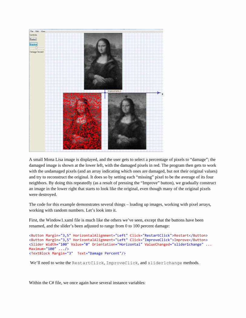
A small Mona Lisa image is displayed, and the user gets to select a percentage of pixels to “damage”; the damaged image is shown at the lower left, with the damaged pixels in red. The program then gets to work with the undamaged pixels (and an array indicating which ones are damaged, but not their original values) and try to reconstruct the original. It does so by setting each “missing” pixel to be the average of its four neighbors. By doing this repeatedly (as a result of pressing the “Improve” button), we gradually construct an image in the lower right that starts to look like the original, even though many of the original pixels were destroyed.
The code for this example demonstrates several things – loading up images, working with pixel arrays, working with random numbers. Let’s look into it.
First, the Window1.xaml file is much like the others we’ve seen, except that the buttons have been renamed, and the slider’s been adjusted to range from 0 to 100 percent damage:
<Button Margin="3,5" HorizontalAlignment="Left" Click="RestartClick">Restart</Button> <Button Margin="3,5" HorizontalAlignment="Left" Click="ImproveClick">Improve</Button> <Slider Width="100" Value="0" Orientation="Horizontal" ValueChanged="slider1change" ... Maximum="100" .../> <TextBlock Margin="3" Text="Damage Percent"/> We’ll need to write the RestartClick, ImproveClick, and slider1change methods.
Within the C# file, we once again have several instance variables:
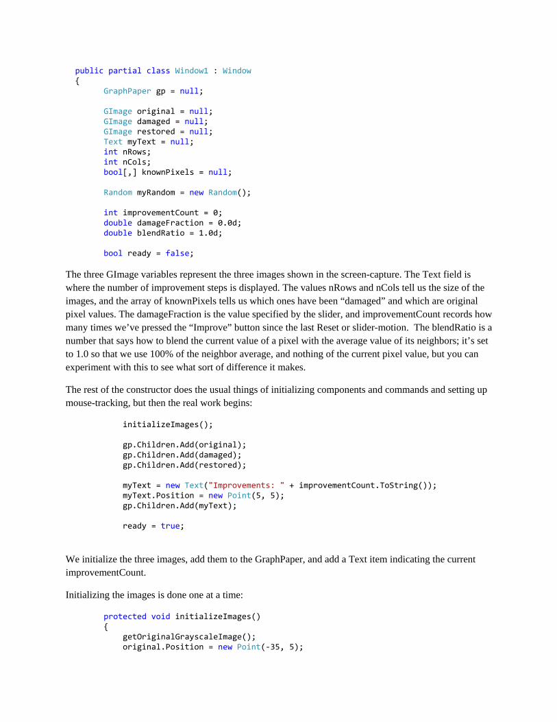
public partial class Window1 : Window { GraphPaper gp = null; GImage original = null; GImage damaged = null; GImage restored = null; Text myText = null; int nRows; int nCols; bool[,] knownPixels = null; Random myRandom = new Random(); int improvementCount = 0; double damageFraction = 0.0d; double blendRatio = 1.0d; bool ready = false; The three GImage variables represent the three images shown in the screen-capture. The Text field is where the number of improvement steps is displayed. The values nRows and nCols tell us the size of the images, and the array of knownPixels tells us which ones have been “damaged” and which are original pixel values. The damageFraction is the value specified by the slider, and improvementCount records how many times we’ve pressed the “Improve” button since the last Reset or slider-motion. The blendRatio is a number that says how to blend the current value of a pixel with the average value of its neighbors; it’s set to 1.0 so that we use 100% of the neighbor average, and nothing of the current pixel value, but you can experiment with this to see what sort of difference it makes.
The rest of the constructor does the usual things of initializing components and commands and setting up mouse-tracking, but then the real work begins:
initializeImages(); gp.Children.Add(original); gp.Children.Add(damaged); gp.Children.Add(restored); myText = new Text("Improvements: " + improvementCount.ToString()); myText.Position = new Point(5, 5); gp.Children.Add(myText); ready = true;
We initialize the three images, add them to the GraphPaper, and add a Text item indicating the current improvementCount.
Initializing the images is done one at a time:
protected void initializeImages() { getOriginalGrayscaleImage(); original.Position = new Point(-35, 5);
knownPixels = new bool[nRows, nCols]; buildDamagedImage(); damaged.Position = new Point(-70, -95); buildRestoredImage(); restored.Position = new Point(5, -95); }
As you can see, each image is created and then positioned to that it’ll be in the right place on the GraphPaper.
Getting the original image requires a little work: we first read the image from a file, but it’s a color image. To convert it to grayscale, we take a pixel with RGB values r, g, and b and replace each with (r + g + b)/3.
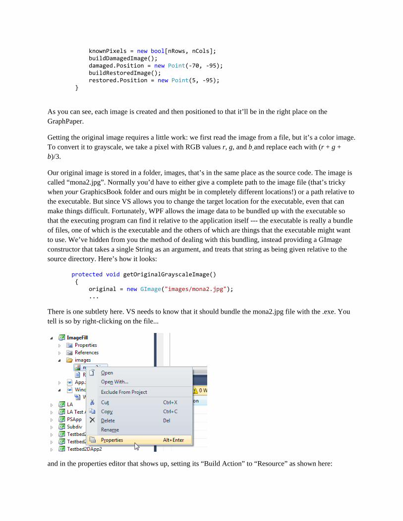
Our original image is stored in a folder, images, that’s in the same place as the source code. The image is called “mona2.jpg”. Normally you’d have to either give a complete path to the image file (that’s tricky when your GraphicsBook folder and ours might be in completely different locations!) or a path relative to the executable. But since VS allows you to change the target location for the executable, even that can make things difficult. Fortunately, WPF allows the image data to be bundled up with the executable so that the executing program can find it relative to the application itself --- the executable is really a bundle of files, one of which is the executable and the others of which are things that the executable might want to use. We’ve hidden from you the method of dealing with this bundling, instead providing a GImage constructor that takes a single String as an argument, and treats that string as being given relative to the source directory. Here’s how it looks:
protected void getOriginalGrayscaleImage() { original = new GImage("images/mona2.jpg"); ... There is one subtlety here. VS needs to know that it should bundle the mona2.jpg file with the .exe. You tell is so by right-clicking on the file...
and in the properties editor that shows up, setting its “Build Action” to “Resource” as shown here:

We now have the image loaded, but we need to convert its pixels to gray. A GImage has a GetPixelArray method that returns an nRows x nCols x 4 array of bytes, each group of four representing the value of one image pixel. The first three bytes contain the red, green, and blue values, and the last contains the “alpha value”, representing how opaque this pixel happens to be. In this program, we’ll always set the alpha value to 255, or “fully opaque.”
With this understanding, we loop through all pixels, compute the grey values, and store these in another array, which we then use to set the pixel array for the image, producing a grayscale copy of the Mona Lisa:
byte[, ,] pixels = original.GetPixelArray(); nRows = original.PixelHeight(); nCols = original.PixelWidth(); byte[, ,] gPixelArray = new byte[nRows, nCols, 4]; for (int i = 0; i < nRows; i++) { for (int j = 0; j < nCols; j++) { int grayValue = 0; for (int k = 0; k < 3; k++) { grayValue += pixels[i, j, k]; } grayValue /= 3; for (int k = 0; k < 3; k++) { gPixelArray[i, j, k] = (byte) grayValue; } gPixelArray[i, j, 3] = 255; } } original.SetPixelArray(gPixelArray, nRows, nCols); }
Notice that this establishes the values nRows and nCols, which we’ll use from now on.
Building the damaged image is easy: we start with an array of all zeros:
protected void buildDamagedImage() {
byte[] pixelVector = new byte[nRows * nCols * 4]; damaged = new GImage(nRows, nCols, pixelVector); damaged.Position = new Point(-95.0, 0.0); updateDamagedImage(); }
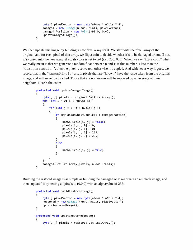
We then update this image by building a new pixel array for it. We start with the pixel array of the original, and for each pixel of that array, we flip a coin to decide whether it’s to be damaged or not. If not, it’s copied into the new array; if so, its color is set to red (i.e., 255, 0, 0). When we say “flip a coin,” what we really mean is that we generate a random float between 0 and 1; if this number is less than the “damageFraction”, then the pixel is set to red; otherwise it’s copied. And whichever way it goes, we record that in the “knownPixels” array: pixels that are “known” have the value taken from the original image, and will never be touched. Those that are not known will be replaced by an average of their neighbors. Here’s the code:
protected void updateDamagedImage() { byte[, ,] pixels = original.GetPixelArray(); for (int i = 0; i < nRows; i++) { for (int j = 0; j < nCols; j++) { if (myRandom.NextDouble() < damageFraction) { knownPixels[i, j] = false; pixels[i, j, 0] = 0; pixels[i, j, 1] = 0; pixels[i, j, 2] = 255; pixels[i, j, 3] = 255; } else { knownPixels[i, j] = true; } } } damaged.SetPixelArray(pixels, nRows, nCols); }
Building the restored image is as simple as building the damaged one: we create an all black image, and then “update” it by setting all pixels to (0,0,0) with an alphavalue of 255:
protected void buildRestoredImage() { byte[] pixelVector = new byte[nRows * nCols * 4]; restored = new GImage(nRows, nCols, pixelVector); updateRestoredImage(); }
protected void updateRestoredImage() { byte[, ,] pixels = restored.GetPixelArray();

for (int i = 0; i < nRows; i++) { for (int j = 0; j < nCols; j++) { pixels[i, j, 0] = 0; pixels[i, j, 1] = 0; pixels[i, j, 2] = 0; pixels[i, j, 3] = 255; } } restored.SetPixelArray(pixels, nRows, nCols); } In this case, “update” is really just a part of “initialize.” The real work is done in the improveRestoredImage() method: for each pixel, if it’s a “known” pixel, we just copy the original pixel into the restored image pixel. But if not, we look at the four neighbors (above, below, left, right) of the pixel, sum up their gray values, and divide by the number of neighbors. (That number isn’t always 4, because for a pixel on the left edge, for instance, there’s no pixel to the left, etc.) This neighbor average is used to set the pixel value:
protected void improveRestoredImage() { byte[, ,] originalPixels = original.GetPixelArray(); byte[, ,] pixels = restored.GetPixelArray(); for (int i = 0; i < nRows; i++) { for (int j = 0; j < nCols; j++) { if (knownPixels[i, j]) { pixels[i, j, 0] = originalPixels[i, j, 0]; pixels[i, j, 1] = originalPixels[i, j, 0]; pixels[i, j, 2] = originalPixels[i, j, 0]; pixels[i, j, 3] = 255; } else { double neighborSum = 0; int neighborCount = 0; getNeighbors(pixels, i, j, out neighborSum, out neighborCount); double val = neighborSum / neighborCount; pixels[i, j, 0] = (byte) Math.Round(((1 - blendRatio) * pixels[i, j, 0] + blendRatio * val)); pixels[i, j, 1] = pixels[i, j, 0]; pixels[i, j, 2] = pixels[i, j, 0]; pixels[i, j, 3] = 255; } } } restored.SetPixelArray(pixels, nRows, nCols); }
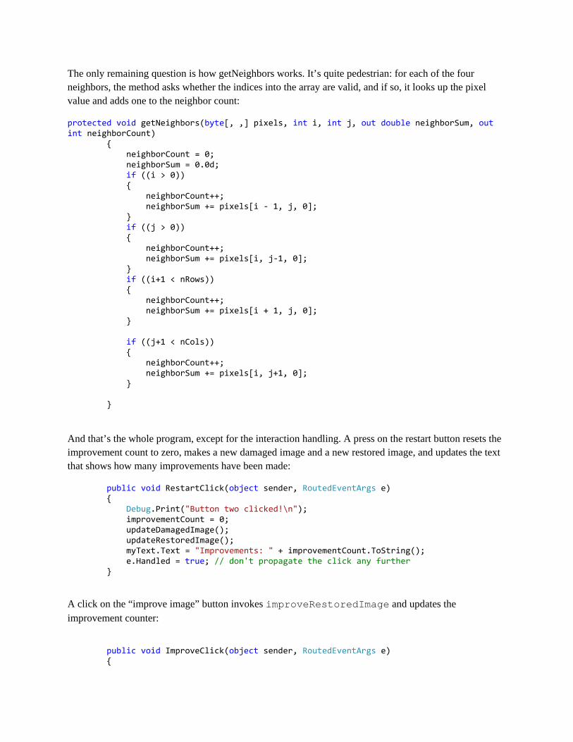
The only remaining question is how getNeighbors works. It’s quite pedestrian: for each of the four neighbors, the method asks whether the indices into the array are valid, and if so, it looks up the pixel value and adds one to the neighbor count:
protected void getNeighbors(byte[, ,] pixels, int i, int j, out double neighborSum, out int neighborCount) { neighborCount = 0; neighborSum = 0.0d; if ((i > 0)) { neighborCount++; neighborSum += pixels[i - 1, j, 0]; } if ((j > 0)) { neighborCount++; neighborSum += pixels[i, j-1, 0]; } if ((i+1 < nRows)) { neighborCount++; neighborSum += pixels[i + 1, j, 0]; } if ((j+1 < nCols)) { neighborCount++; neighborSum += pixels[i, j+1, 0]; } }
And that’s the whole program, except for the interaction handling. A press on the restart button resets the improvement count to zero, makes a new damaged image and a new restored image, and updates the text that shows how many improvements have been made:
public void RestartClick(object sender, RoutedEventArgs e) { Debug.Print("Button two clicked!\n"); improvementCount = 0; updateDamagedImage(); updateRestoredImage(); myText.Text = "Improvements: " + improvementCount.ToString(); e.Handled = true; // don't propagate the click any further } A click on the “improve image” button invokes improveRestoredImage and updates the improvement counter:
public void ImproveClick(object sender, RoutedEventArgs e) {
Debug.Print("Button one clicked!\n"); improvementCount++; myText.Text = "Improvements: " + improvementCount.ToString(); improveRestoredImage(); e.Handled = true; // don't propagate the click any further } And finally, a change in the slider does everything that “Reset” does, but also sets up a new damageFraction by dividing the slider value by 100:
void slider1change(object sender, RoutedPropertyChangedEventArgs<double> e) { Debug.Print("Slider changed, ready = " + ready + ", and val = " + e.NewValue + ".\n"); e.Handled = true; if (ready) { improvementCount = 0; myText.Text = "Improvements: " + improvementCount.ToString(); damageFraction = e.NewValue / 100; updateDamagedImage(); updateRestoredImage(); } }
If you’re interested, you could play with a few experiments, like adjusting the blendFraction, or perhaps by initializing the improved image with random gray values rather than with all black.