an introduction to dmx and e1.31 for pixel control · an introduction to dmx and e1.31 for pixel...
TRANSCRIPT
Page 1
An Introduction to DMX and E1.31 for Pixel Control
October 27, 2015
V1.7
Copyright © Light O Rama, Inc. 2015
All Rights Reserved
Page 2
Preface
This document is intended for customers who have decided on using pixels and possibly E1.31, but who
do not know where to begin when considering how to connect all the devices. You are probably just
starting out in the world of pixels and have discovered that things are not as easy as they appear.
E1.31/Ethernet/IP networking will add an entire layer of complexity on top of the burden of learning
how to program pixels, dealing with RGB, etc. The fact is that unless you have studied networking, you
are going to quickly find out that most pixel controllers/E1.31 things are not plug and play.
However being a Light-O-Rama customer means that you may not even need to consider moving to
E1.31 at all, while still being able to enjoy all the benefits of a Pixel Based display. LOR has enabled
several different technologies within the newest versions of our software and firmware to enable you to
run pixel displays without the need to ever learn E1.31. Since all of these technologies are much easier
to use than learning the ins and outs of E1.31 you will most likely have more success learning to use
them rather than IP Networking.
That means that even if you are not computer savvy, you can still enjoy creating a high-tech pixel
display. If you want all the wow with a minimum of fuss, you should consider using Light-O-Rama
Cosmic Color Pixel products and our PixCon16:
Cosmic Color Bulbs and their cousins Cosmic Color Pixels consist of two 50 count pixel strings
and a weather resistant controller. Each bulb is RGB and individually controllable. They are
fully contained and require no other equipment to run.
Cosmic Color Ribbons are 50 pixel flat ribbons that consist of 150 LEDs – 3 RGB LEDs per pixel.
They also come with their own controller and power supply.
The PixCon16 is a 16 port smart pixel string driver, where each port can handle up to 340 pixels.
The controller can run in E1.31 or LOR mode. In LOR Mode the board appears to be 16 units
each with 170 pixels. If in the future you decide to use E1.31 the PixCon16 is ready.
The very first section of this document titled “Pixels without E1.31 – Yes it can be done” explains how to
easily incorporate, or start, a pixel display.

Page 3
Table of Contents Preface .......................................................................................................................................................... 2
Pixels without DMX and E1.31 – Yes it can be done! ................................................................................... 5
Going forward with E1.31 ............................................................................................................................. 6
Before you start -- Get a separate router! .................................................................................................... 7
No wireless! .............................................................................................................................................. 7
A Simple Setup (the “I don’t want to learn anything” setup) ................................................................... 8
The easiest way ......................................................................................................................................... 8
The easiest way Part 2 - Separate with part time internet ..................................................................... 10
I’m out of LAN Ports!................................................................................................................................... 11
Intermediate and Advanced Setups History and Background .................................................................... 12
Basic Networking .................................................................................................................................... 12
Ethernet and TCP/IP ............................................................................................................................ 12
Addresses ............................................................................................................................................ 13
TCP and UDP ....................................................................................................................................... 13
Layers .................................................................................................................................................. 13
Why not Ethernet to start with? ......................................................................................................... 13
The Pixel Explosion .............................................................................................................................. 14
How does DMX-512 work? ..................................................................................................................... 14
DMX Channels ..................................................................................................................................... 14
DMX Universes .................................................................................................................................... 15
Network Configuration and Universes ................................................................................................ 15
DMX-512 Example: Sending letters ................................................................................................... 16
How does E1.31 Work? ........................................................................................................................... 17
The E1.31 Application Layer ................................................................................................................ 18
E1.31 Multicast Example: Sending a LOT of letters ........................................................................... 18
What is Multicast? .............................................................................................................................. 19
What is Unicast? ................................................................................................................................. 20
E1.31 Unicast Example: Sending only the letters you need. .............................................................. 22
Multicast vs. Unicast: .......................................................................................................................... 23
Summation .............................................................................................................................................. 23
Intermediate Networking ....................................................................................................................... 24
Static and Dynamic IP addresses......................................................................................................... 24
Page 4
What is a network according to TCP/IP .............................................................................................. 24
What’s this thing called a ‘Network Mask’? ....................................................................................... 25
An Intermediate Setup ................................................................................................................................ 26
Static IPs with Unicast ......................................................................................................................... 26
An Advanced Setup ..................................................................................................................................... 27
The postman learns a new route ........................................................................................................ 27
Gateways ............................................................................................................................................. 27
Basic Routing ....................................................................................................................................... 28
Default Routes and HOPping .............................................................................................................. 29
Danger Abounds! ................................................................................................................................ 30
It Gets Worse ...................................................................................................................................... 30
Two LANs with Routing – A How To .................................................................................................... 31
Important Last Words ................................................................................................................................. 34
Page 5
Pixels without DMX and E1.31 – Yes it can be done!
The easiest way to enjoy a new Pixel Display element is to continue to use what you already know and
understand: Light-O-Rama networks. While E1.31 does have some advantages over LOR based
networking, if you feel more comfortable with LOR networking and technologies, by all means stick with
them.
Deciding to use Pixels is already a large step into the unknown. There are many different concepts that
you’ll need to learn before you can become proficient in their use:
What Exactly IS a pixel?
How are Pixels addressed?
What different types of pixel drivers are there?
What is Power Injection?
What is DMX?
Many MANY more.
Those topics are beyond the scope of this document. Instead the main thrust of the following sections is
to help those who want to use E1.31 hardware and LOR Software. We warn you – even the ‘simple’
E1.31 configurations shown require some in depth computer knowledge.
On the other hand, Light-O-Rama Pixel Products like our Cosmic Color Pixels, Cosmic Color Bulbs, and
even our PixCon16 can be run on RS485 adapters and wiring that you are already familiar with.
For Example, our PixCon16 is a ‘dual use’ board. In one mode it will run as an E1.31 controller, however
when in LOR mode it runs and looks like a normal LOR controller – just one with a lot of channels and
pixel control!
A PixCon16 running at our new 1000K speed on an Enhanced LOR network can control between 2000-
2500 pixels. For example, you could attach 100 pixels to each pixel port of a PixCon16. With proper
configuration you could then assign a single LOR Unit ID to each port. If you are familiar with our Cosmic
Color Pixels/Bulbs, what you have now is in essence 16 CCP/CCB controllers on a single board. Each
pixel will have a Unit ID, and an RGB Triplet (3 channels) – both concepts you already understand.
When it comes time to set up, you configure a LOR USB adapter or LOR Generation 3 MP3 director just
like you would for any other LOR device. Daisy chain to the PixCon16, and the setup is complete.
One of the main reasons people use E1.31 is for transmission speed. Ethernet is many times faster than
our RS485 connections. However, an LOR network at 1000K speed is enough to run 2000-2500 pixels in
your display. To give you an idea of what you can do with a few thousand pixels, take a look at our
website and view our ‘Cosmic Color Tree’ videos. The trees in those videos are using 800 pixels OR LESS.
With 1000K LOR network you could have 3 of them – all without the need to go to E1.31!
If you are at all uncomfortable with any of the topics presented in the rest of this document, stick with
LOR mode. You will be much happier.
Page 6
Going forward with E1.31
A side bar to our fellow network savvy folks:
Please excuse many of these analogies and what are really OVERLY GROSS simplifications of
many of the concepts presented. The reasons for this document aren't so much as to make
network experts out of users or to even be absolutely 100% factually correct, it is to allow some
concepts basic to using E1.31 to be grasped. If you feel the need to start correcting things
because they are not 100% technically correct, please stop reading. If however you understand
where we going and we ended up on a wrong tangent please tell us. Remember, this document
shoots for accessibility over technicalities.
We have done our best to provide you with a couple of E1.31 solutions that should be easy enough to
implement without going too into depth over things. In an effort to help those who just want something
to work, we present those solutions first. HOWEVER, those solutions are not the best nor even
recommended way of doing things. We suggest that you read this ENTIRE document, and then decide
how you want to proceed. Yes there are some slightly complex concepts presented but once you can
grasp them, and this document tries to make that simple, you will have a much more robust
configuration.
Page 7
Before you start -- Get a separate router!
Before you even get started with setup, go out and purchase a new router for your Lighting Controllers.
Everything we discuss in the rest of this document is going to use a separate router for your E1.31
controllers. Yes, you can use lighting controllers successfully on an existing LAN ----IF---- you know how
to set up routing tables, have managed switches, etc. If you are reading this document you probably
DON'T have those skills, so plan on purchasing a separate router for your E1.31 network.
We’ll make the decision easy for you: Have you ever taken and passed a college level networking class?
Yes
Why are you even reading this document?
No
Go buy a separate router.
No wireless! Ok, so we were unable to convince you to use LOR networks to run your Pixel Display, and you want to
forge ahead with E1.31. Please remember that you will NOT be connecting via WIRELESS to this
network, or any existing network. You must plan on using a hard wired connection. If the computer you
plan on using has a wireless connection, turn it OFF. The router you purchase may have wireless. Don’t
use it. Turn it off if you can. Only by completely separating this computer from the rest of your
computers, and that includes connecting wirelessly to an existing network, can you ensure you won't
break anything. This will hold true of ALL the configurations that we will discuss.
Again, yes you can successfully use wireless *IF* you know exactly what you are doing. If you know
exactly what you are doing, you are probably not reading this document.
Page 8
A Simple Setup (the “I don’t want to learn anything” setup) Let's talk about a couple of VERY simple setups. In this document we'll go from very easy, where you
don't need to remember much of what is in the rest of this document, up to multi-routed advanced
networks. Like everything in life, the easier to create setups are the least flexible. As you get more
complex, you have more flexibility - and a lot more ways to shoot yourself in the foot.
We will also be talking mostly about the PixCon16 and a standard Windows computer with standard off
the shelf parts. Because there are so many different Window's systems and a lot of different routers out
there we can't really talk specifics. That is, we can't tell you 'Click here, change this to that value', but
you should be able to take this information and combine it with the documentation from Windows, the
router’s help file, and everything else and use it.
Another thing to remember: There is absolutely NOTHING wrong with running multiple
communications methods from the same computer. It is completely OK to use a USB LOR Network, a
USB DMX Network AND E1.31 all at the same time. Any combination is OK as well. If you have existing
LOR devices that are working fine on a LOR USB adapter – LEAVE THEM ALONE!
The easiest way Ok, you really don't want to deal with anything and are afraid (rightly so) about taking down your home
network with all these lighting commands. After all a teenage child who can't stream is like....well... We
know it's not pretty. Networking equipment is more inexpensive than the audiologist visit you will need
due to a screaming kid causing you deafness.
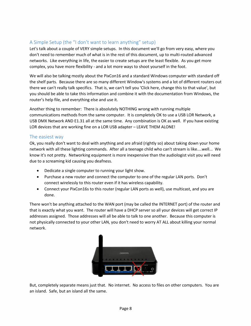
Dedicate a single computer to running your light show.
Purchase a new router and connect the computer to one of the regular LAN ports. Don’t
connect wirelessly to this router even if it has wireless capability.
Connect your PixCon16s to this router (regular LAN ports as well), use multicast, and you are
done.
There won't be anything attached to the WAN port (may be called the INTERNET port) of the router and
that is exactly what you want. The router will have a DHCP server so all your devices will get correct IP
addresses assigned. Those addresses will all be able to talk to one another. Because this computer is
not physically connected to your other LAN, you don't need to worry AT ALL about killing your normal
network.
But, completely separate means just that. No internet. No access to files on other computers. You are
an island. Safe, but an island all the same.
Page 9
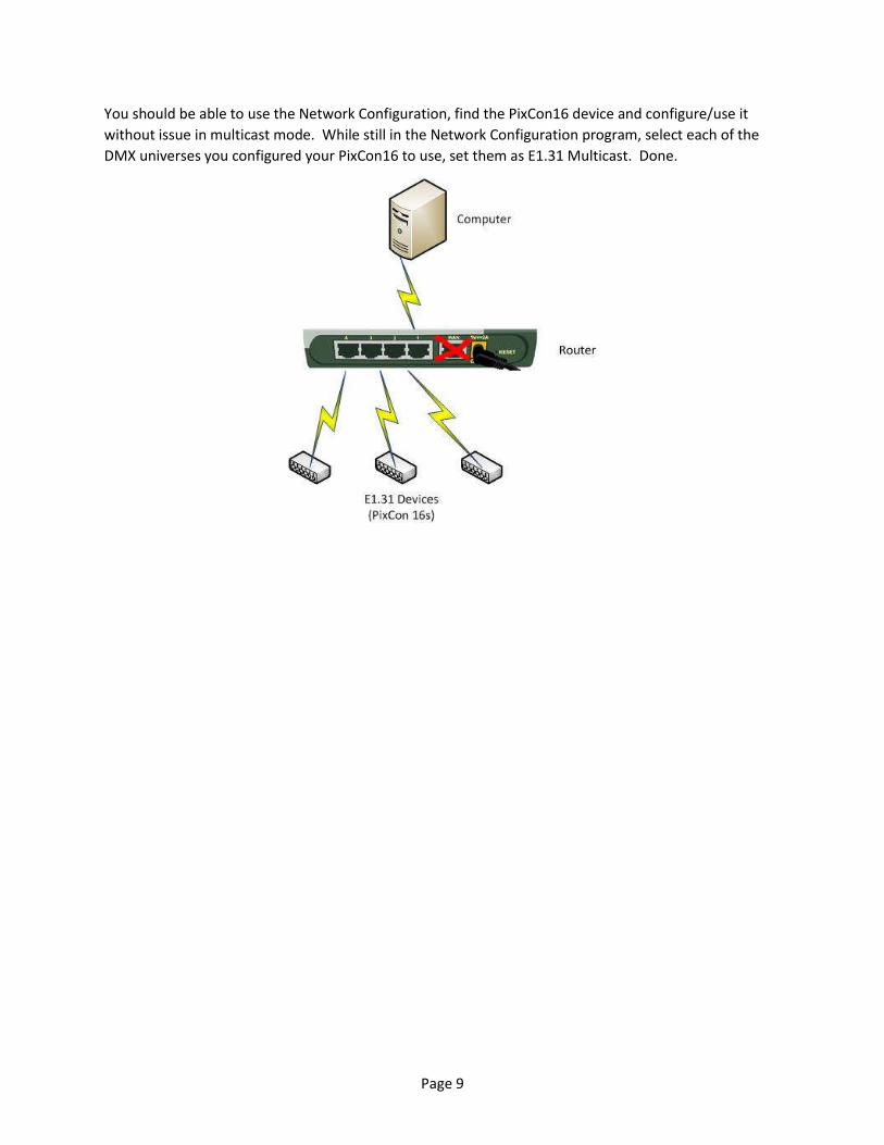
You should be able to use the Network Configuration, find the PixCon16 device and configure/use it
without issue in multicast mode. While still in the Network Configuration program, select each of the
DMX universes you configured your PixCon16 to use, set them as E1.31 Multicast. Done.
Page 10
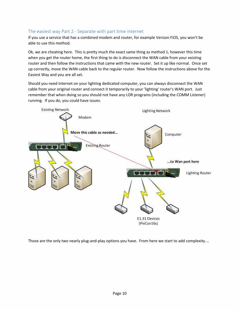
The easiest way Part 2 - Separate with part time internet If you use a service that has a combined modem and router, for example Verizon FiOS, you won't be
able to use this method.
Ok, we are cheating here. This is pretty much the exact same thing as method 1, however this time
when you get the router home, the first thing to do is disconnect the WAN cable from your existing
router and then follow the instructions that came with the new router. Set it up like normal. Once set
up correctly, move the WAN cable back to the regular router. Now follow the instructions above for the
Easiest Way and you are all set.
Should you need Internet on your lighting dedicated computer, you can always disconnect the WAN
cable from your original router and connect it temporarily to your 'lighting' router's WAN port. Just
remember that when doing so you should not have any LOR programs (including the COMM Listener)
running. If you do, you could have issues.
Those are the only two nearly plug-and-play options you have. From here we start to add complexity....
Page 11
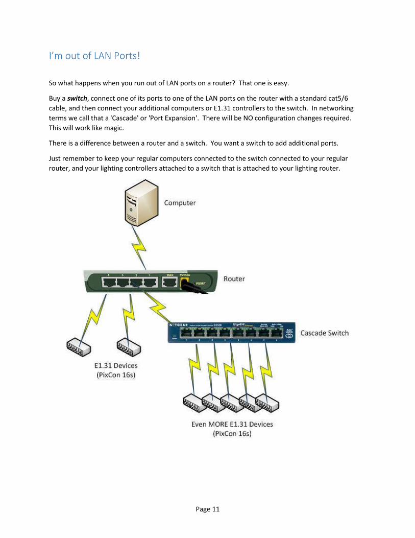
I’m out of LAN Ports!
So what happens when you run out of LAN ports on a router? That one is easy.
Buy a switch, connect one of its ports to one of the LAN ports on the router with a standard cat5/6
cable, and then connect your additional computers or E1.31 controllers to the switch. In networking
terms we call that a 'Cascade' or 'Port Expansion'. There will be NO configuration changes required.
This will work like magic.
There is a difference between a router and a switch. You want a switch to add additional ports.
Just remember to keep your regular computers connected to the switch connected to your regular
router, and your lighting controllers attached to a switch that is attached to your lighting router.
Page 12
Intermediate and Advanced Setups
History and Background Before the advent of DMX and E1.31, LOR (the company) could control the entire user experience. It
didn't matter if you used our adapters or an existing serial port, everything only worked ONE way, OUR
way. Since we invented it we could make it easy to use. In fact, Light-O-Rama’s networking and
protocols are much more robust than what was eventually settled on – DMX.
At the time LOR hardware and software was coming out there were various incompatible ways to talk to
theatrical lighting being shopped around by many different companies. Finally in 2004 the industry
settled on something called DMX-512. DMX-512 is a robust signaling system and works great. The only
real drawbacks with it is that it only supports 512 channels, and the speed is set such that there is no
extra head-room.
Now back when DMX came out, 512 channels was A LOT. This was the time where if a customer had
128 or more channels they were considered huge. Even theaters didn't have a need for more than 512
channels, with all their spots, gobos, lasers, and dimmers.
Advance a few years and this new thing called 'the Pixel' comes knocking. Pixels combine single bulb
control, with any color any time all at a relatively inexpensive price.
Now, DMX can perfectly support 512 channels at a frame rate that makes it quite smooth to the human
eye. BUT the physical transmission is saturated at that point. There is no more room, called Bandwidth,
to send more channel data out. Some quick division will tell you that the maximum number of pixels a
DMX universe can support is 170 (512 divided by 3 is 170 pixels with 2 channels left over and unused).
The solution is of course to add additional physical DMX networks. Each network requires a physical
port and physical wiring. 16 universes of pixels will take 16 separate COM ports, with 16 sets of cables.
That is a lot of cables. We should also mention that when pixels burst onto the scene, many users were
already planning on using more than 16 universes of them. A new communications method was
needed.
Basic Networking Concurrent with all these lighting/DMX advancements way back when something else started to make
the mainstream and that thing was networking computers together. Networked computers could all
share data, and do so rather quickly. The concept of networking itself had been around for quite some
time - even into the early 1950s, but like the lighting control issues in the 2000’s it was on incompatible
hardware. There were many different physical connections to be had: Token Ring, Ethernet, FDDI, and
ARCNET to name a few.
Ethernet and TCP/IP Technology and the marketplace absolutely HATE multiple standards. Eventually one will win: Ethernet.
Page 13
Ethernet only refers to the PHYSICAL connection between devices. It is the ‘electrical signaling system’.
How the devices talk to one another is different and is called PROTOCOL.
Protocols are an accepted system of rules that physical devices use to talk to one another. Again, there
were many different protocols out there at one time: IPX/SPX, X.25, AX.25, AppleTalk, TCP/IP, and
more.
Broken Record Time: Technology and the marketplace, absolutely HATE multiple standards. Eventually
one family will win - TCP/IP.
Addresses One of the core concepts of TCP/IP is the IP Address. EVERY device on your network will have a UNIQUE
address assigned to it. For now, don’t be bogged down by how the device gets the address or even
what it looks like. Just remember it will be UNIQUE within a network.
TCP and UDP So here is TCP/IP and all of its technology. It allows us to successfully send data back and forth between
2 or more computers, and allows us to do so in several different ways. The two most common ways are
called TCP and UDP. We won't get into heavy specifics -- Those of you who are network savvy will
probably cringe at my gross over simplification here. For the rest of you there is only one thing to
remember: using TCP guarantees successful transmission, UDP does not. With TCP each side will
ACKnowledge transmissions. UDP on the other hand is NOT guaranteed to get to the receiver. The
sender will send the data out, but does not wait for an ACK. TCP=Slower and guaranteed, UDP=Faster
and packets can be dropped/corrupted. E1.31 will end up using UDP since the data is not ‘critical’. Do
not confuse UDP with MULTICAST. We will talk more about Multicast later on.
Layers Now there is one more part we are interested in. Up to now, we have been building up one thing on top
of another. In fact in network speak each of these things is called a 'Layer'. We have the Link layer
(Ethernet), the Internet Layer (IP - Addressing), and the Transport Layer (TCP). How should two
APPLICATIONS talk to one another? That's the last layer, the Application Layer. The Application layer is
the set of rules that 2 programs, or as you eventually see 2 pieces of lighting hardware, talk to one
another.
Why not Ethernet to start with? Taking a step back in time, we find that not all of these things happen at once, or even happen quickly.
When there are multiple competing technologies out there, prices remain high until one wins AND is
widely adopted. LOR came onto the scene during the time when Ethernet was just winning out. Prices
were still prohibitively expensive for networking hardware since it had not yet been widely adapted. In
order to produce something cost-effective LOR (and later the consortium that came up with DMX)
would select RS-485 – a technology that had already won out for distance and reliability in other
applications.
RS485 has a great number of advantages: It can be sent long distances, is pretty resistant to noise, had
plenty of bandwidth (for 512 channels), and most importantly it was already in wide use. For those of
you wondering why LOR didn't start out using Ethernet, there is your answer.
Page 14
The Pixel Explosion If you have not been put to sleep yet, you'll see the great collision that is about to happen: Inexpensive
networking, inexpensive LEDs, inexpensive pixel communications, entrenched users with large amounts
of cash already invested, and standards that will eventually unite everything.
We call it the 'Pixel Explosion'.
We have these now cheap pixels, we have this now cheap networking, and we have an existing
transmission system that is bursting at the seams. The solution? Marry them. Thus the E1.31 standard
(ACN) is born.
Repeat after us: E1.31 is DMX over TCP/IP. E1.31 does nothing more than allow the transmission of
DMX data over TCP/IP. We realize you probably don’t know what any of that means, but it is the
important first concept that you must learn, upon which everything else will be built.
How does DMX-512 work? So, in order to fully understand how E1.31 works, we must first understand how DMX-512 works.
The DMX-512 specification tells us exactly HOW we are to talk between a sender and a receiver. It
documents exactly what the format of the message is, and the transmission medium of that message.
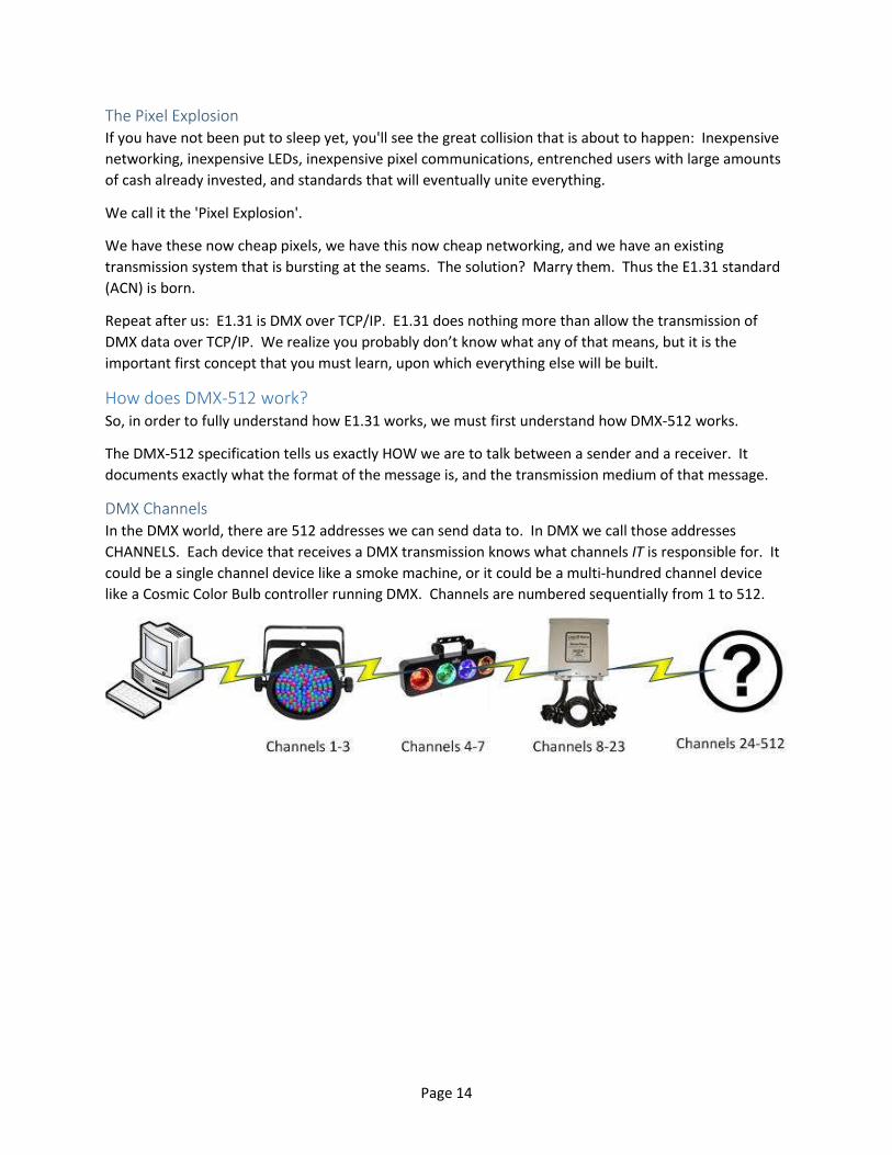
DMX Channels In the DMX world, there are 512 addresses we can send data to. In DMX we call those addresses
CHANNELS. Each device that receives a DMX transmission knows what channels IT is responsible for. It
could be a single channel device like a smoke machine, or it could be a multi-hundred channel device
like a Cosmic Color Bulb controller running DMX. Channels are numbered sequentially from 1 to 512.
Page 15
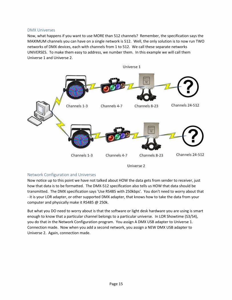
DMX Universes Now, what happens if you want to use MORE than 512 channels? Remember, the specification says the
MAXIMUM channels you can have on a single network is 512. Well, the only solution is to now run TWO
networks of DMX devices, each with channels from 1 to 512. We call these separate networks
UNIVERSES. To make them easy to address, we number them. In this example we will call them
Universe 1 and Universe 2.
Network Configuration and Universes Now notice up to this point we have not talked about HOW the data gets from sender to receiver, just
how that data is to be formatted. The DMX-512 specification also tells us HOW that data should be
transmitted. The DMX specification says 'Use RS485 with 250kbps'. You don't need to worry about that
- it is your LOR adapter, or other supported DMX adapter, that knows how to take the data from your
computer and physically make it RS485 @ 250k.
But what you DO need to worry about is that the software or light desk hardware you are using is smart
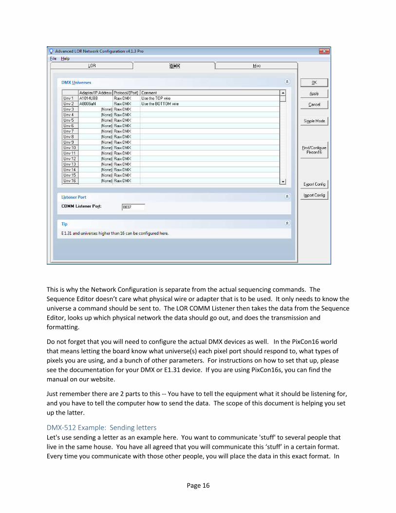
enough to know that a particular channel belongs to a particular universe. In LOR Showtime (S3/S4),
you do that in the Network Configuration program. You assign A DMX USB adapter to Universe 1.
Connection made. Now when you add a second network, you assign a NEW DMX USB adapter to
Universe 2. Again, connection made.
Page 16
This is why the Network Configuration is separate from the actual sequencing commands. The
Sequence Editor doesn’t care what physical wire or adapter that is to be used. It only needs to know the
universe a command should be sent to. The LOR COMM Listener then takes the data from the Sequence
Editor, looks up which physical network the data should go out, and does the transmission and
formatting.
Do not forget that you will need to configure the actual DMX devices as well. In the PixCon16 world
that means letting the board know what universe(s) each pixel port should respond to, what types of
pixels you are using, and a bunch of other parameters. For instructions on how to set that up, please
see the documentation for your DMX or E1.31 device. If you are using PixCon16s, you can find the
manual on our website.
Just remember there are 2 parts to this -- You have to tell the equipment what it should be listening for,
and you have to tell the computer how to send the data. The scope of this document is helping you set
up the latter.
DMX-512 Example: Sending letters Let's use sending a letter as an example here. You want to communicate 'stuff' to several people that
live in the same house. You have all agreed that you will communicate this ‘stuff’ in a certain format.
Every time you communicate with those other people, you will place the data in this exact format. In
Page 17
this case, we will write it on a piece of paper in a particular order with a particular number of characters
per person.
Concept 1: DMX-512 is the standard that defines how the information is written on the paper –
the order and number of characters. (A 'DMX Frame')
Now, to get this information to the other party, you fold up the paper and walk it directly to the house.
Concept 2: DMX-512 ALSO defines the type of paper to use, how to walk and how often. (Using
RS485 @ 250kbps)
Each person (channel) you want to communicate with will get the exact same message. However, not
all of the information written on the paper is for them. They do know however which pieces belong to
them. They will copy them out of the message, and then pass the entire message along to the next
person.
Concept 3: The channel is born. A device knows it handles channels 3,4,5,6. It will look at the
message, copy the data for channels 3,4,5,6 and pass the entire message on. Another device
knows it handles channels 12-50. It copies that data and sends it along to the next channel.
This works great. Until one day you have more people than can fit in a house. Your standard only allows
you to communicate with 512 people, numbered 1-512. The solution is to build a second house and
write TWO letters, one to each home. You call each house a 'Universe', and you number each universe
to keep them separate: 1 and 2.
Concept 4: A DMX Universe is born. You walk letter 1 over to universe 1 – because you know
what sidewalk to use, and letter 2 over to universe 2. The Sidewalk is the connection that is
defined in the Network Configuration program.
Honestly -- That is ALL there is to it. You want your smoke machine to come on? You know it is on
universe 2 and is listening to channel 15. In your sequence you have a channel that says 'Smoke
Machine'. It is defined as DMX, Universe 2, Channel 15. You turn the channel ON. Showtime runs the
sequence, and sees a command that needs to go to Universe 2, channel 15. It determines which
physical connection it needs to use, and then inserts the data into the DMX frame. When it is time to
transmit the frame, out the correct wire it goes. The smoke machine knows that it listens to channel 15.
It extracts the Channel 15 data from the frame. It says TURN ON. It does. Easy.
How does E1.31 Work? Again, all of this works great for a couple of universes worth of data. You only have a couple of
adapters, a couple of cables, and all is well. A few years later you look into the cost of adding a pixel
tree, something which will consume 16 universes of pixels all on its own. You are IN! In fact, you want
to add TWO of them! 32 universes of action packed pixel perfection.
Wow, that also means a total of 34 adapters and 34 cables running off your computer to the devices.
Doubtful your computer could even handle that many USB adapters, and who really wants to deal with
THIRTY FOUR cables!? We’d go crazy drawing that, so no picture for you!
But wait a minute. You are a modern person, with a modern computer, and you have this thing called a
LAN. It is thousands of times faster than that USB adapter, and you can buy the stuff at WALMART!
Page 18
Why can't we transmit all this data over the LAN? You can, and that's what E1.31/ACN allows. What did
we ask you to repeat a few paragraphs back? E1.31 is NOTHING MORE than DMX over TCP/IP.
The E1.31 Application Layer Remember during the start of this we talked about the different 'Layers' of communication on a LAN,
and we glossed over the 'Application' layer? Guess where E1.31/ACN fits in? It is the APPLICATION
LAYER. Just like DMX-512 (which is actually called standard E1.11), E1.31 tells us the exact format we
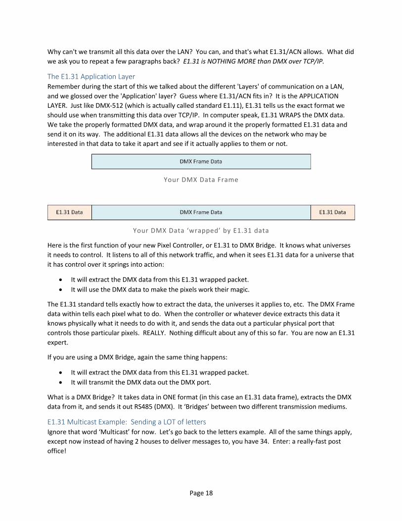
should use when transmitting this data over TCP/IP. In computer speak, E1.31 WRAPS the DMX data.
We take the properly formatted DMX data, and wrap around it the properly formatted E1.31 data and
send it on its way. The additional E1.31 data allows all the devices on the network who may be
interested in that data to take it apart and see if it actually applies to them or not.
Your DMX Data Frame
Your DMX Data ‘wrapped’ by E1.31 data
Here is the first function of your new Pixel Controller, or E1.31 to DMX Bridge. It knows what universes
it needs to control. It listens to all of this network traffic, and when it sees E1.31 data for a universe that
it has control over it springs into action:
It will extract the DMX data from this E1.31 wrapped packet.
It will use the DMX data to make the pixels work their magic.
The E1.31 standard tells exactly how to extract the data, the universes it applies to, etc. The DMX Frame
data within tells each pixel what to do. When the controller or whatever device extracts this data it
knows physically what it needs to do with it, and sends the data out a particular physical port that
controls those particular pixels. REALLY. Nothing difficult about any of this so far. You are now an E1.31
expert.
If you are using a DMX Bridge, again the same thing happens:
It will extract the DMX data from this E1.31 wrapped packet.
It will transmit the DMX data out the DMX port.
What is a DMX Bridge? It takes data in ONE format (in this case an E1.31 data frame), extracts the DMX
data from it, and sends it out RS485 (DMX). It ‘Bridges’ between two different transmission mediums.
E1.31 Multicast Example: Sending a LOT of letters Ignore that word ‘Multicast’ for now. Let’s go back to the letters example. All of the same things apply,
except now instead of having 2 houses to deliver messages to, you have 34. Enter: a really-fast post
office!
Page 19
So here you have 34 letters that have information for 512 people each. You are only one person, so it's
impossible to walk all this data over yourself. You have a plan. Rather than deliver the information
yourself you make 34 copies of EACH letter, you place each letter in an envelope, number the envelope
with the universe number, then hand those 1156 (that's 34 times 34) total envelopes to the post office.
Concept 5: E1.31 is nothing but an envelope for your data. It holds the DMX data along with
identifying information so a house can identify if a particular letter applies to it or not.
You throw these 1156 letters at the post office who INSTANTLY takes 34 letters -- one copy of each
letter, and gives a batch to a house. It does the SAME thing for all 34 houses at once. All 34 houses get
34 letters each.
Now if a house sees an envelope that it needs, it passes the letter amongst the people living there.
Otherwise it throws away the envelope and the letter.
Concept 6: Remember- The data the DMX-512 standard has defined says NOTHING about the
Universe the data actually belongs to. Before we physically had separate wires to send the
separate data. Not so with TCP/IP. One of the things the additional E1.31 data wraps around
the DMX data is a universe number. Your E1.31 controller is smart enough to know what E1.31
data applies to it, and which it should just discard.
From this point forward everything works exactly the same. The people know their channel number,
etc....
What is Multicast? What we have just described is the easiest of E1.31 networks to use and is called MULTI-CAST:
MULTI=Many, CAST=to throw - as in the word broadCAST. Why Multi-cast? Because all 34 universes of
data are presented to devices without regard to what they actually want. Remember, we said the post
office is delivering 34 GROUPS of letters to all 34 addresses at the same time. The post man has NO
IDEA the contents, he just knows he has to bring a copy of EACH letter to all the houses. In terms of data
that would mean 34*34, or 1156 total letters sent, while only 34 were actually used - each house will
use 1 envelope's data and discard the other 33.
Turn on an FM Radio and listen to a station. That's a lot like MULTI-CAST. They are sending from a
single source all these songs that you may or may not be interested in. You tune into the station. The
songs you like, you listen to. The others, you ignore. And so do the other 50,000 people listening to the
same station at the same time.
Page 20
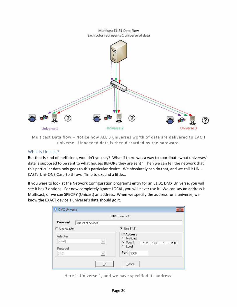
Multicast Data flow – Notice how ALL 3 universes worth of data are delivered to EACH
universe. Unneeded data is then discarded by the hardware.
What is Unicast? But that is kind of inefficient, wouldn't you say? What if there was a way to coordinate what universes’
data is supposed to be sent to what houses BEFORE they are sent? Then we can tell the network that
this particular data only goes to this particular device. We absolutely can do that, and we call it UNI-
CAST: Uni=ONE Cast=to throw. Time to expand a little...
If you were to look at the Network Configuration program’s entry for an E1.31 DMX Universe, you will
see it has 3 options. For now completely ignore LOCAL, you will never use it. We can say an address is
Multicast, or we can SPECIFY (Unicast) an address. When we specify the address for a universe, we
know the EXACT device a universe’s data should go it.
Here is Universe 1, and we have specified its address.
Page 21
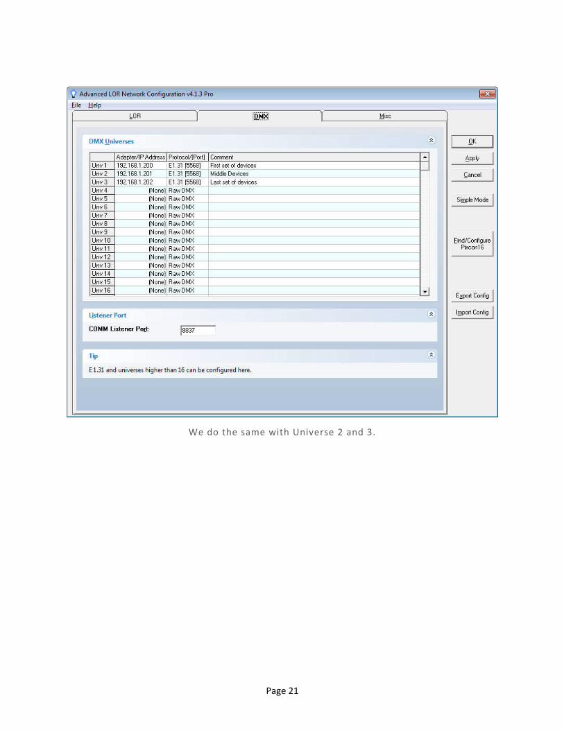
We do the same with Universe 2 and 3.
Page 22
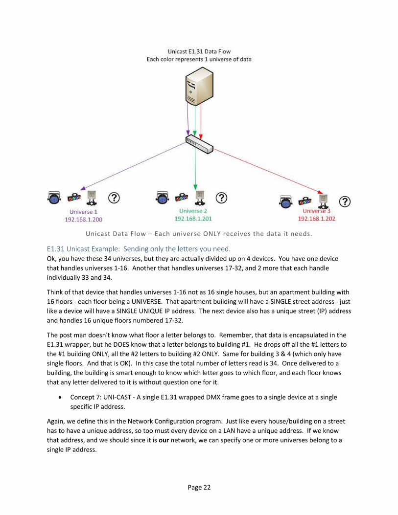
Unicast Data Flow – Each universe ONLY receives the data it needs.
E1.31 Unicast Example: Sending only the letters you need. Ok, you have these 34 universes, but they are actually divided up on 4 devices. You have one device
that handles universes 1-16. Another that handles universes 17-32, and 2 more that each handle
individually 33 and 34.
Think of that device that handles universes 1-16 not as 16 single houses, but an apartment building with
16 floors - each floor being a UNIVERSE. That apartment building will have a SINGLE street address - just
like a device will have a SINGLE UNIQUE IP address. The next device also has a unique street (IP) address
and handles 16 unique floors numbered 17-32.
The post man doesn't know what floor a letter belongs to. Remember, that data is encapsulated in the
E1.31 wrapper, but he DOES know that a letter belongs to building #1. He drops off all the #1 letters to
the #1 building ONLY, all the #2 letters to building #2 ONLY. Same for building 3 & 4 (which only have
single floors. And that is OK). In this case the total number of letters read is 34. Once delivered to a
building, the building is smart enough to know which letter goes to which floor, and each floor knows
that any letter delivered to it is without question one for it.
Concept 7: UNI-CAST - A single E1.31 wrapped DMX frame goes to a single device at a single
specific IP address.
Again, we define this in the Network Configuration program. Just like every house/building on a street
has to have a unique address, so too must every device on a LAN have a unique address. If we know
that address, and we should since it is our network, we can specify one or more universes belong to a
single IP address.
Page 23
Multicast vs. Unicast: So why would you ever use MULTI-CAST over UNI-CAST? There are two main reasons. Firstly, it is
usually much easier to set a board up to use Multicast than Unicast. By simply telling the board what
universes it controls, it will implicitly know what IP addresses to listen to. Unicast will also traverse a
routed network without any additional routing information needed. That is a double edged sword -
while the packets will do their best to find their way home, they can also decide to go out your internet
connection to be filtered by your ISP -- Which may then turn off your service since it will appear to be an
attack. Secondly, it is the only way to allow boards to control duplicate universes. If you want universe
23 on 2 different boards, Multicast is the only way to do it - since you can't assign 2 IP addresses to a
single universe, nor can you assign a single IP address to 2 or more devices.
Summation Wow, that is a LOT of background. Let's review just the main points we are REALLY interested in.
1 - DMX-512 is nothing but a standard that says how lighting 'things' can communicate with one
another. It specifies both the format of the data and the connection between devices.
2 - E1.31 is nothing but a standard that allows us to send DMX data over a LAN by wrapping additional
identifying information around the DMX data.
3 - Each device on a network must have a unique network (IP) address, no exceptions.
4 - While a device must have a unique IP address it can control 1 or more DMX universes.
5 - There are two different transmission types when it comes to E1.31 - Multicast where ALL boards
receive ALL data for ALL universes, and Unicast where only the correct device gets the data for the
universes it controls.
6 - Multicast is initially simpler to configure, but can quickly degrade your network and if incorrectly
configured (or used on an existing LAN) can render the rest of the LAN unusable.
7 - Unicast reduces network congestion, at the cost of needing to properly configure your devices and
network. It is the PREFERED method, but does take some additional setup.
8 – Setting up an E1.31 Pixel Controller involves more than just what is in this document. This document
takes care of how to talk to the control board. You also have to properly configure the control board
itself.

Page 24
Intermediate Networking We do need to talk about some slightly advanced topics when it comes to networking. Don’t worry,
they are easy to grasp.
Static and Dynamic IP addresses Now that we have broken the ice about IP addressing let's talk about that a little more. We already
know that every device attached to a network must have a unique IP address. But how does that
happen? There are two ways, called 'Static' and 'Dynamic'.
Dynamic is what 99.9% of you use, probably without even knowing it. Dynamic IP addresses are
assigned by a device on your network, usually a router. You may have seen something called a 'DHCP'
server. That is the thing responsible for setting addresses and networking parameters when you are
using dynamic addressing.
The DHCP server will assign a unique IP address to a device that requests one. It will also send along
some additional information like how to get to different networks, name lookup locations, etc. The
problem with DHCP is that the address for a device could change if you power it or the router off.
Static addresses on the other hand DON'T change. Since you explicitly set a static address, a device will
keep that address forever. The down side is that you have to keep track of all the addresses that you
have assigned.
Remember, duplicate IP addresses are not allowed. If you are unlucky enough to have assigned a
duplicate IP address to something, you will go crazy trying to figure out what has gone wrong. Some
devices will randomly work, then stop working for no reason. Sometimes both devices will work.
Sometimes neither. The best solution to this is decidedly LOW tech. Take a piece of paper and write
down the addresses in use and what they are supposed to control.
We use something called IPv4 addresses, and you have probably seen them at one time or another.
They are 4 numbers from 0 to 255 that are separated by periods. Almost all of you reading this
document are probably doing so on a computer that currently has an IP address of 192.168.1.xxx, or
192.168.0.xxx.
Address ending in ‘0’ or ‘255’ have special meanings and are typically not used for devices/computers.
The xxxs are therefore going to be a number between 2 and 254. For example, the IP of the computer
we are writing this on is 192.168.1.179. Your IP was most likely assigned by your router using DHCP.
There are also IPv6 addresses. We do not use them. Forget they even exist.
What is a network according to TCP/IP Since we are using the post office metaphor, think of the IP address as being like a COMPLETE building
address. It is broken down into State (192), City (168), Street (1), and building number (179).
Sidebar: Ok network folks, again don’t crucify us here. We are aware that there is a lot more to
this. Remember Accessibility over Technicality.
Important lesson about IP addresses: Without help, computers and devices can only find each other
when they are on the SAME first 3 sets of numbers. That is VERY IMPORTANT to remember. In other
words, according to TCP/IP, 192.168.1.xxx and 192.168.2.xxx are 2 very separate networks, and unless
Page 25
you have done some additional configuration the two can NOT talk to one another – even if they are
hooked up to the same switch/router or even directly to each other!
Here is a prime example. PixCon16s are designed by default to come up as address 192.168.0.50. If
your controller is on 192.168.0.50 and your computer is on 192.168.1.179 they are NOT going to be able
to find each other without help. At this point we should have a discussion on routing, but that is going
to be far too in-depth a topic. We will touch on routing later, but only for ADVANCED users. For now if
you are newbie remember: The first 3 sets of numbers MUST MATCH, or communication won't work.
The postman only knows about buildings on his street. He does not know anything about buildings on
other streets.
What’s this thing called a ‘Network Mask’? DON’T ASK! Really. Don’t even think about it. If at any time you need to know what your ‘Network
Mask’ is, or if some configuration thingy is asking for your network mask, your answer is ALWAYS
255.255.255.0. ALWAYS. It does not matter if you are configuring an E1.31 controller or your Windows
network correction. Pretend you are a recording: ‘The network mask you have reached is
255.255.255.0’.
NO! We will not get into them, or even tell you what those numbers mean. If you do know about them,
and know how to use them, you probably wouldn’t be reading this document to begin with.

Page 26
An Intermediate Setup
Static IPs with Unicast This setup is still physically an island from your existing LAN, so there should still be no problems with
messing up your existing network/computers. Again, dedicate a computer and a new router and hook
everything up just as above. Now however you will need to do some configuration.
The first thing you are going to need to know is What IP addresses your router is serving up. In Windows
press the start button and then type CMD. Click on the program that says 'CMD', and you will open up a
Command Window. In that window type "ipconfig" and press enter. Look at the line that says IPv4
address and write it down. For me, mine says 192.168.1.179. You can close that window.
The MOST important thing to remember is those first 3 sets of numbers are going to have to be the
same.
Repeat: If the first 3 sets of numbers don’t match, it’s like talking to a teenager or a wall – you are NOT
getting through to them.
Your network address will most likely start with 192.168. The next number set is usually 0 or 1, and the
last number set could be anything from 2-254. Examples: 192.168.0.77, 192.168.1.33.
So it is those first 3 sets that are important. For our computer it's 192.168.1. Now configure your
PixCon16 and select STATIC as the IP type. Change the address fields to 192.168.1.xxx where xxx is a
number from 2-254 and is UNIQUE. In other words no other device (including the computer you are
using) can have that address. If you saw 192.168.99.33, set the board address to 192.168.99.xxx. If you
saw 192.168.0.77, set the board address to 192.168.0.xxx. Get it?
Your board is now set up to use static addresses, which means you can now use Unicast. Again in the
Network Configuration program, go into each universe you configured on the board, select 'Specify' and
then type in the boards IP address.
You are probably wondering ‘Can I use Unicast with Dynamic IP addresses?’ The answer is yes, but you
are probably not going to like it. Remember Unicast wants to send data directly to a device. To do that
you need the IP address. However when using Dynamic (DHCP assigned) addresses, IP addresses can
change. Your board may have been 192.168.1.233 yesterday when you booted it up and configured.
However today when you booted it up, the DHCP server gave it an address of 192.168.1.211. Your
software is still going to be sending data to 192.168.1.233 and nothing will work.
Page 27
An Advanced Setup
All of this has been wonderful, but your light show computer is still on an island - it has no other
connectivity to the internet or other computers you may have. We can fix that - but we will warn you
now:
This is the first configuration that if you don't do it JUST right, you will cause all kinds of trouble
on your network. If all of a sudden no one can get the internet, Netflix stops working, or you’ve
suddenly gone deaf due to teen-age screams, disconnect the new router, reboot your network,
do a factory reset on the new router, and start again.
You will definitely have to be computer literate to use this setup. You WILL need to know how to do
things like Configure Windows, and routers.
Oh, and we lied earlier when we said no more learning. We do have to do some more learning to make
this work, but we didn’t want to discourage all those people who just want plug-and-play-ish setups.
The postman learns a new route Back when we were talking about the postman, you'll remember we said he only knew about the houses
on his own street - those last set of numbers in the IP address. That is absolutely true - but there is a way
for your postman to get information to another postman who can then deliver it.
In our networking world, the postman is the router. The postman has connections to one or more
buildings on his street - those are the regular LAN ports. LAN = LOCAL Area Network. A typical home
router will have 4 of them. But he also has an additional connection to the world- the WAN port. WAN=
WIDE Area Network. If you have correctly taught the postman, he knows what data is his, and what
data isn't. If it is not his data, he sends it out the WAN port to someone else.
Gateways This WAN port is the GATEWAY (another networking term) to the rest of the world. The rest of the
world could be as simple as other computers in your house/business, or that one in Japan that is serving
up your favorite Anime. When the WAN port is connected to another network, your router has in effect
TWO addresses. It has the one on YOUR side, the LAN side - those are the 3 starting numbers in an IP,
plus the fourth to make it unique. It will also have an address on the WAN side which is completely
different, where one or more of the first 3 numbers DON’T match. Those 3 numbers are actually the
network number of the ‘next higher’ LAN the WAN is connected to. When we say ‘Next Higher’ we
don’t mean in value – like an IP address, we mean in a hierarchy. Pictures will improve things:
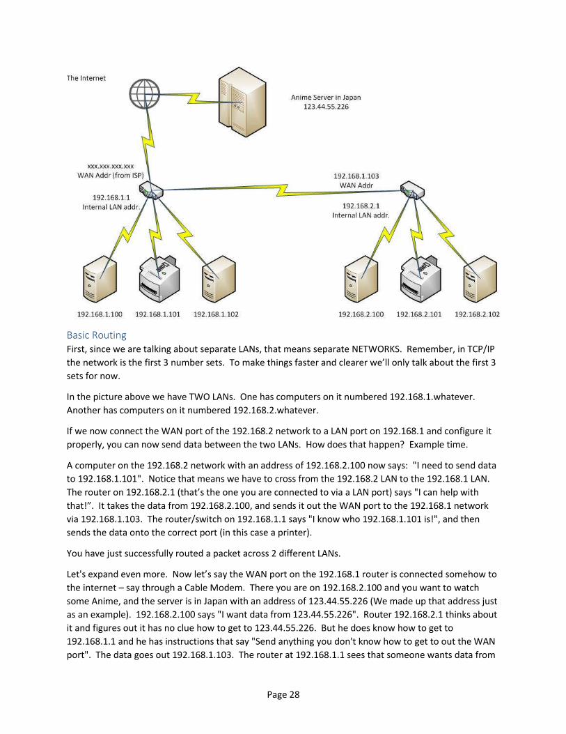
Page 28
Basic Routing First, since we are talking about separate LANs, that means separate NETWORKS. Remember, in TCP/IP
the network is the first 3 number sets. To make things faster and clearer we’ll only talk about the first 3
sets for now.
In the picture above we have TWO LANs. One has computers on it numbered 192.168.1.whatever.
Another has computers on it numbered 192.168.2.whatever.
If we now connect the WAN port of the 192.168.2 network to a LAN port on 192.168.1 and configure it
properly, you can now send data between the two LANs. How does that happen? Example time.
A computer on the 192.168.2 network with an address of 192.168.2.100 now says: "I need to send data
to 192.168.1.101". Notice that means we have to cross from the 192.168.2 LAN to the 192.168.1 LAN.
The router on 192.168.2.1 (that’s the one you are connected to via a LAN port) says "I can help with
that!”. It takes the data from 192.168.2.100, and sends it out the WAN port to the 192.168.1 network
via 192.168.1.103. The router/switch on 192.168.1.1 says "I know who 192.168.1.101 is!", and then
sends the data onto the correct port (in this case a printer).
You have just successfully routed a packet across 2 different LANs.
Let's expand even more. Now let’s say the WAN port on the 192.168.1 router is connected somehow to
the internet – say through a Cable Modem. There you are on 192.168.2.100 and you want to watch
some Anime, and the server is in Japan with an address of 123.44.55.226 (We made up that address just
as an example). 192.168.2.100 says "I want data from 123.44.55.226". Router 192.168.2.1 thinks about
it and figures out it has no clue how to get to 123.44.55.226. But he does know how to get to
192.168.1.1 and he has instructions that say "Send anything you don't know how to get to out the WAN
port". The data goes out 192.168.1.103. The router at 192.168.1.1 sees that someone wants data from
Page 29
123.44.55.226. He too has no idea how to get to that computer and so he too sends it out the WAN
port. Do that many more times, and you have (big booming voice) THE INTERNET!
Simply put - IP packets want nothing more than to find their way home. They will do everything in their
power to get home. It would be completely impractical for every device on the network/Internet to
know the exact way to EVERY home (Best Carl Sagan voice: BILLIONS and BILLONS of computers), so
they HOP from WAN to LAN looking to get there. All routers, including the two you have sitting there,
have something known as a 'default gateway'. Basically the default gateway is there to allow packets a
way to travel when the destination ROUTE is unknown.
Default Routes and HOPping The router on 192.168.2.1 had no clue how to get to network 123.44.55 since it was not in ROUTING
TABLE. But he does know the default gateway is his connection to 192.168.1.1. He sends the data that
way via 192.168.1.103 and lets 192.168.1.1 deal with it. Problem is, 192.168.1.1 doesn't know what to
do with it either. EXACT same thing happens - he sends the data out the WAN port which is his default
gateway. The packet continues on its way… Eventually a packet will hit a router that says "Hey! I know
how to get to the 123.44.55 network!" and it will go out that direction. Each time a packet goes from
one router to another, or from computer to router, it is called a HOP.
Here is a sample of a route from 208.101.16.73, the address of one of our web servers to 206.190.36.45
which is one of the Yahoo servers:
1 208.101.16.73 208.101.16.73-static.reverse.softlayer.com
2 66.228.118.153 ae11.dar01.sr01.dal01.networklayer.com
3 173.192.18.210 ae6.bbr01.eq01.dal03.networklayer.com
4 206.223.118.2 exchange-cust2.da1.equinix.net
5 216.115.96.58 ae-3.pat2.dnx.yahoo.com
6 216.115.96.62 ae-6.pat2.gqb.yahoo.com
7 66.196.67.101 unknown-66-196-67-x.yahoo.com
8 67.195.1.165 xe-1-2-1.clr1-a-gdc.gq1.yahoo.com
9 67.195.1.85 et-18-1.fab4-1-gdc.gq1.yahoo.com
10 206.190.32.19 po-12.bas1-7-prd.gq1.yahoo.com
11 206.190.36.45 ir1.fp.vip.gq1.yahoo.com
It took 11 hops to get from here to there. #1 is our source computer (our server), and #11 is the
destination computer. Each #2-#10 are routers. Each time the packet stopped at a HOP and asked 'How
do I get to 206.190.36.45'. Each router then took the packet and either passed it out its default gateway
(it didn't know), or a router said "I know how to get there!" and it went out that way. Eventually it gets
where it needs to go.
Page 30
Danger Abounds! “Easy peasy!” you say. Not so fast pilgrim. The waters here are fraught with danger. It is VERY easy to
mess up your routing to the point that packets start leaking out into other networks where they don't
belong, start traveling in circles, or worse. For you with only 2 separate LANs and Unicast it is going to
be difficult to mess up. If you decide to add a third (or more) LAN with routing between the 2 others,
beware.
Even more dangerous is that you could incorrectly type an IP address. Instead of assigning universe 32
to 192.168.1.44, you assign it to 192.167.1.44. Not only aren't those packets going to make it to
192.168.1.44 and turn the lights on, they are going to 'leak' out of your LAN, follow the default gateway
path and start bombing some unexpected person on the other side of the world! In fact, you could be
shooting out so many packets that your internet connection grinds to a halt because of all the data.
Your ISP may see all those packets flooding out of your connection and say "Hey! He's got a virus or
something nasty!" and simply turn your access OFF. It has happened.
It is important to remember that routing has absolutely NOTHING to do with the software, be it Light-O-
Rama Showtime or any other control platform. All any of them do is say ‘Here is some data for IP
address xxx.xxx.xxx.xxx’. It is then up to your routing hardware, which includes the computer you are
running on and any routers on the same network. There is nothing special you can do in ANY software,
apart from correctly configure it, which will control how packets go out.
The biggest complaint we hear from customers is that our software is breaking their network. In fact
what is broken is the configuration of your network. Take another look at the last diagram. Now ask: If
I send a packet to 192.168.0.50 (which is the default address of a PixCon16) where does it go? Notice
we did not say which computer was sending the request because it doesn’t matter – I can tell you right
now it is going out to the internet. Why?
“Simply put - IP packets want nothing more than to find their way home.” Pretend you are any of the
computers in that diagram. Ask the router that computer is connected to ‘How do I get to the
192.168.0’ network?’ Do you know the router’s answer? The answer ANY router on your network will
give is ‘I have no clue, but I do know how to go out the default gateway’. Hop. Hop. Internet.
It Gets Worse Assume you are using MULTICAST, watch what happens now. We said that Multicast is easy to
configure since you don’t need to know how your network is set up. And that is correct – until your
network isn’t set up the same way anymore.
Let’s say that you want to send a packet to universe 7. You have defined Universe 7 to be Multicast.
That means your computer sends a packet out to the network on 239.255.0.7 – the Multicast address
for Universe 7. That is a special address that makes your router ask all the devices connected to it:
“HEY! Who is interested in multicast data for 239.255.0.7?” Your PixCon16 that is controlling Universe
7 will speak up and say ‘ME!’ The packet will then be passed to that device.
But what happens when nothing on the network says ‘I want that data’? Maybe you just don’t have
those boards powered up. What is IP best at? “Simply put - IP packets want nothing more than to find
their way home.” Can you guess where the packets are going to go if no one inside says they want
them? Correct – they are going right out the default gateway AGAIN. (Technically, Multicast packets
Page 31
are SUPPOSED to be non-routable: That is once they hit a roadblock, like a LAN to WAN transition, they
are supposed to stop. Not all home routers are smart enough to do that however).
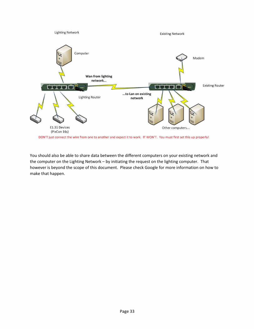
Two LANs with Routing – A How To Ok, enough background. Let's get back to interconnecting those two networks. This is going to take
some know-how and time.
The first thing to do is determine what IP addresses your current router is serving up. Do it the same
way as above with the IPCONFIG command. Let’s say that you find a computer hooked to your existing
LAN has an address of 192.168.1.100. That means that LAN is using the 192.168.1 network. You also
need to know the IP address of your existing router. If you found 192.168.1.whatever as your IP, then
the router is most likely 192.168.1.1. Don't guess however - you absolutely need to know this address.
99 out of 100 times the routers address is the 'Default Gateway' that is displayed in the IP config
command.
Now, disconnect a computer from that LAN, and connect it to your NEW router via the LAN port. This
computer should ONLY be connected to the new router. If the computer also has a wireless connection,
use Windows to TURN IT OFF. Reboot, and then go into the setup of your router. Most routers have a
web page interface, and the instructions that came with it will tell you how to access it.
You will need to set some IP addresses on this new router and after each change the router may need to
reboot. You may also need to reboot your computer (or if you know how - release/renew your lease).
The first address you need to change is the IP address of the router itself. This will usually be shown as
LOCAL IP or LAN IP address. Be careful - the WAN or INTERNET section will look nearly identical. We are
not changing that. Yet. Change that IP address to a NEW network. That is, change the THRID set of
numbers. For example, if you had found your normal router on 192.168.1.1, this network has to be
something DIFFERENT. We recommend 2, making the IP address 192.168.2.1. Once you save that, the
router is going to reboot, and you may need to reboot your computer as well.
By changing the IP of the router you actually changed the NETWORK the router is running. This is now
network 2.
Now, the next thing you may need to change is the DHCP server. Again, log into your lighting router and
find the DHCP settings page. DHCP should be ENABLED. Some routers allow you to specify a range of IP
addresses that the DHCP server can give out. If yours does, verify that the addresses start with
192.168.2.whatever.
Remember, DHCP does more than just send an IP address to someone who requests it. It also sends
other network configuration information that we must now update.
Next step. Change the 'Default Gateway' to the IP address of your original router - in our example that is
192.168.1.1. That is most likely going to be on the main or start page of the router. Remember all that
talk above how packets want to find a way home and where they go if they don't know how to get
there? This sets the default gateway.
We also need to set something known as a DNS server. Quickly, a DNS server is what takes a site's
name, like www.lightorama.com and turns it into an IP address. It's like a telephone book look up. Your
original router should have a DNS server built in as well, so set the PRIMARY DNS to 192.168.1.1. We

Page 32
also need a secondary DNS. In case the first one can't find the domain name, the second one will try.
For that specify 8.8.8.8. Yes, EXACTLY 8.8.8.8. What is that? That is the IP address of the GOOGLE
Public DNS server. More information on it can be found here -
https://developers.google.com/speed/public-dns/?hl=en. You could use any other public DNS server, or
the DNS server that your ISP provides, but you are on your own if you do. The Google DNS is useable by
anyone, and we don’t have to explain how to find your ISP’s DNS server. Save that page, and the router
will most likely reboot again, and you may need to reboot your computer as well.
Nearly there. What we have done so far is create a completely separate network along with all the
parameters to support it. Now we need to configure the connection from THIS router to your ORIGINAL
router. Now is the time to update the WAN/INTERNET section.
This is the main function of a router, so this could be called something like SETUP or NETWORK/WAN, or
just may be on the main page of the router. This part is VERY EASY. Ensure the WAN connection type is
set to 'Dynamic IP'. and save. You may see other options in the connection type like Static IP, PPPoE,
PPTP, and possibly others. You want Dynamic IP – that is because your EXISTING Router (the one on
192.168.1.1) is serving up dynamic addresses and we want one too.
Here comes the magic. Power down both your existing router and your new lighting network router.
Connect a CAT5/6 cable from the WAN port on the LIGHTING network router to a LAN port on your
existing router. Power up your existing router, wait for it to completely boot, then power up your
lighting network router. Run some tests.
With this configuration, you should be able to reach the internet from your 'lighting' computer. All of
your existing computers should continue to work the exact same way. Configure your E1.31 boards to
use Unicast with a unique static IP that starts 192.168.2.xxx. To do that, use the Static IPs with Unicast
section above, but you can ignore the part about being completely separate – because you are cool.
The reason you don’t want to jump data across the 2 LANs is simply to keep things uncluttered in terms
of data. By only running lighting on the lighting router, and other stuff on your existing router your data
is SEGMENTED (another networking term).
Page 33
You should also be able to share data between the different computers on your existing network and
the computer on the Lighting Network – by initiating the request on the lighting computer. That
however is beyond the scope of this document. Please check Google for more information on how to
make that happen.
Page 34
Important Last Words
As you can see, things become complex in a short amount of time. To tell you the truth, we have not
even begun to scratch the surface of all the different methods that can be used to successfully run a
light show and your existing devices/computers. For example, another setup for those who know about
routing is to use two Network Cards in one computer. Once card connects to their existing LAN, the
other to the lighting network. This configuration requires knowing how to set up routing tables on your
computer. Again, if you are reading this document that is probably a skill you don't have - stick to the
methods above.