an introduction to application customization …...–take full advantage of the ansys workbench...
TRANSCRIPT

© 2011 ANSYS, Inc. May 10, 2012 1
An Introduction to Application Customization Toolkit (ACT) and Examples
Presented at the 2012 Confidence by Design Workshop
May 8, 2012
© 2011 ANSYS, Inc. May 10, 2012 2
• Positioning:
– ACT is an easy-to-use and comprehensive toolkit for performing customization within ANSYS Mechanical
• Key point: Usability
– User skill required for effectively using ACT is somewhere between an application engineer and a programmer, and no need for a compiler
• Targeted-beta at R14 (select customers and partners)
– ACT is scheduled to be released commercially in R14.5
• Components: ACT Module (free for beta) and derived ACT-based extensions (not licensed)
– Both require presence of an ANSYS Mechanical license to run
• Supported & Documented
Snapshot at R14

© 2011 ANSYS, Inc. May 10, 2012 3
• Encapsulate APDL macros: Allows re-use of legacy APDL-scripts and encourages migration from MAPDL to Mechanical via “encapsulated macros”
• MAPDL exposure: Fills the gap between MAPDL solver capabilities and their exposure in ANSYS Mechanical
• New pre-processing features (custom loads and boundary conditions)
• New post-processing features (custom results)
• 3rd party/in-house solver integration (Mechanical GUI)
Scope

© 2011 ANSYS, Inc. May 10, 2012 4
Examples

© 2011 ANSYS, Inc. May 10, 2012 5
FEInfo extension

© 2011 ANSYS, Inc. May 10, 2012 6
• Apply a convective boundary condition to the blade surface in a 2D axi-symmetric analysis
• Instead, expose the same functionality via ACT
2D Convection Load extension
Need to apply a convective boundary condition to this surface
Since the model is 2D, convective boundary condition is allowed only on edges! Using a command snippet we can apply the convection load to the surface!

© 2011 ANSYS, Inc. May 10, 2012 7
! APDL_script_for_convection.inp /prep7 thickness = 0.001 film_coefficient = 200. temperature = 120 cmsel,s,component *GET,n_el,ELEM,0,num,max *GET,mat1, ELEM,n_el,ATTR,MAT et,100,152 keyop,100,8,2. et,1001,131 keyo,1001,3,2 sectype,1001,shell secdata,thickness,mat1 secoff,mid emodif,all,type,1001 emodif,all,secnum,1001 type,100 esurf fini alls /solu esel,s,type,,100 nsle sf,all,conv,film_coefficient,temperature allsel, all APDL WB Mechanical
2D Convection Load extension

© 2011 ANSYS, Inc. May 10, 2012 8
Convective surface boundary condition in 2D axi-symmetric analysis
The thickness is mandatory to create the shell elements
Dedicated toolbar and button for object creation One additional convection is created as a new user defined load This convection enables the scope of surfaces or Named Selections Both the transformation from a 2D axi to a 3D shell formulation AND the convection itself are generated

© 2011 ANSYS, Inc. May 10, 2012 9
Clamp and Displace extension
Load Step-1: Apply the pressure Allow the body to bend Load Step-2: Clamp the top surface in its deformed state Load Step-3: Apply a deformation to the clamped surface
LS-1
LS-3
LS-2

© 2011 ANSYS, Inc. May 10, 2012 10
Solution using Command Snippet
Definition based on named selection previously defined
LS 2
LS 3

© 2011 ANSYS, Inc. May 10, 2012 11
Solution using ACT
User inputs in the APDL command snippets are translated to ACT properties related to the newly integrated ACT load: • The location provided by the named selection is now defined based on a scoping method compatible with both named selection and direct geometry selection • The load step number for clamping is available from a drop-down menu initialized with the number of steps already defined in the Analysis Settings object • The X Displacement value for the next load step is defined by a new property declared as a length. This makes this property always consistent with the current unit system activated in Mechanical

© 2011 ANSYS, Inc. May 10, 2012 12
Contact Force Vectors extension
• Contact Force is not available for visualization in Mechanical • In MAPDL, we have access to the contact force components • Using APDL commands, we can get all the force components • Using ACT, we can access the values and visualize the vectors
The Minimum and Maximum values of the result can be defined as “parameter” to perform DP and DX analysis
!

© 2011 ANSYS, Inc. May 10, 2012 13
Animation of Contact Force Vectors

© 2011 ANSYS, Inc. May 10, 2012 14
The ability to deal with maximum admissible criteria represents a common and general request for many customers
Temperature dependent properties are made available in order to compute « relative results » that provide admissible ratios in addition to the other standard results in Mechanical
The scenario as exposed in this example can be enhanced to address any type of mechanical result (strain, stress, displacement…)
“Stress Limit Damage” - Overview

© 2011 ANSYS, Inc. May 10, 2012 15
Post-process the maximum admissible criteria based on temperature dependent properties in Mechanical
The relevant material property are retrieved directly from Engineering Data
The material property can also be defined by the user directly in Mechanical (user defined property)
Stress Limit Damage extension

© 2011 ANSYS, Inc. May 10, 2012 17
Results definition
• Result definition: The user has to select one result that will be divided by the material property in order to get the ratio • Any other result can be added very easily in this result definition.
Two types of results have been integrated: • “Ratio” defines the real final result. It is directly the selected result divided by the material property • “Material property” enables the visualization of the material property itself
Interpolated material property based on the thermal condition
The ratio result has been defined as a result with no associated unit. The current active unit system in Mechanical has no impact on the display
© 2011 ANSYS, Inc. May 10, 2012 18
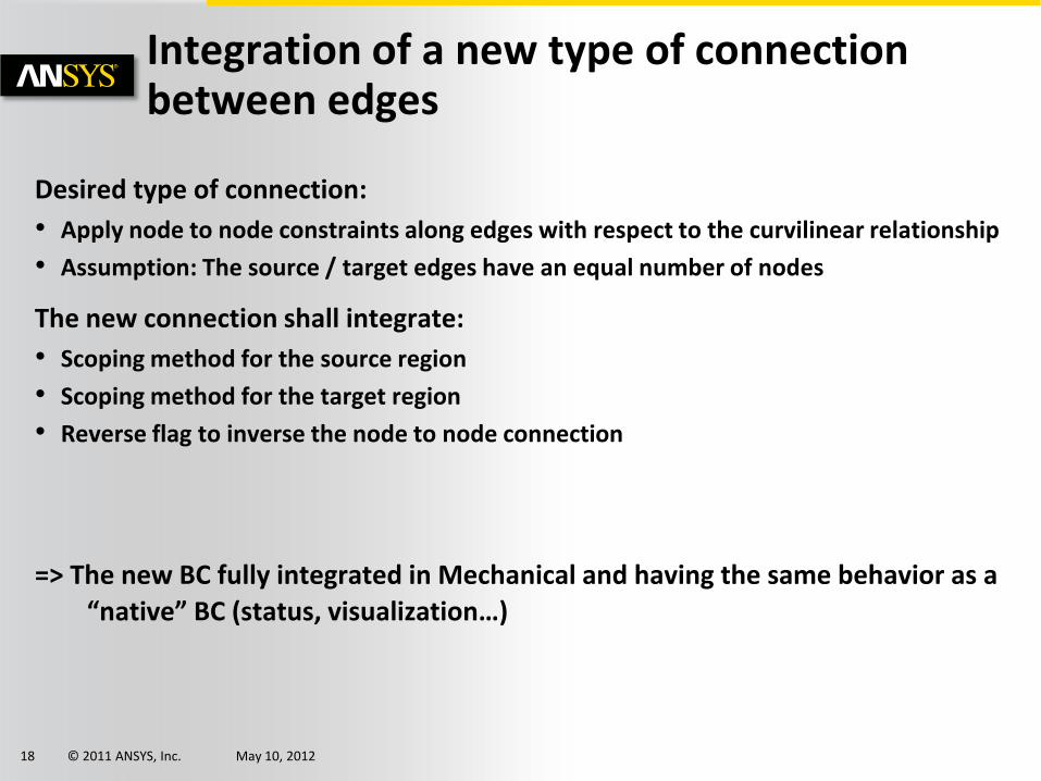
Integration of a new type of connection between edges
Desired type of connection:
• Apply node to node constraints along edges with respect to the curvilinear relationship
• Assumption: The source / target edges have an equal number of nodes
The new connection shall integrate:
• Scoping method for the source region
• Scoping method for the target region
• Reverse flag to inverse the node to node connection
=> The new BC fully integrated in Mechanical and having the same behavior as a
“native” BC (status, visualization…)
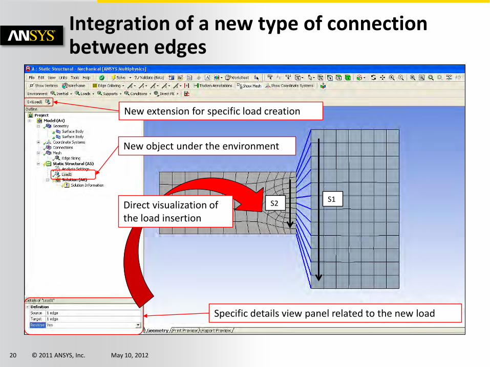
© 2011 ANSYS, Inc. May 10, 2012 20
New extension for specific load creation
New object under the environment
Specific details view panel related to the new load
Direct visualization of the load insertion
S1 S2
Integration of a new type of connection between edges

© 2011 ANSYS, Inc. May 10, 2012 21
Sub-modeling extension
Sub-modeling in Mechanical between 2 structural analysis
– Interpolation of displacement (CBDOF) and temperature (BFINT).
– Choose 2D-2D, 3D-3D or 2D axi-3D sub-modeling
– Choose Solid-solid & Shell-shell key or Solid-shell key
– Tabular data for multi-stepping
The sub-modeling extension was developed as an example just to show the possibility. Since, sub-modeling is scheduled to be released natively in Mechanical at R14.5, the extension is not being developed further or distributed.

© 2011 ANSYS, Inc. May 10, 2012 23
Acoustics extension
Expose Acoustics features in Mechanical via ACT
– Define acoustics elements, real constants & material properties
– Apply acoustics boundary conditions & loads
– Plot Far/Near field & Time/Frequency results
– Post process Pressure & SPL

© 2011 ANSYS, Inc. May 10, 2012 24
Example acoustics simulations
Speaker
Underwater
© 2011 ANSYS, Inc. May 10, 2012 25
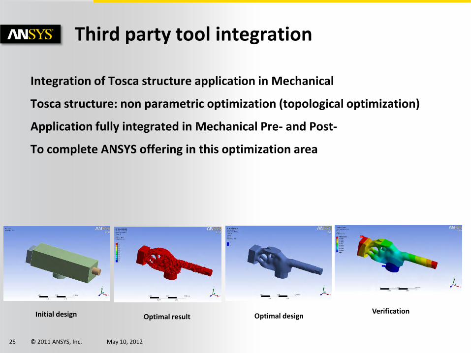
Integration of Tosca structure application in Mechanical
Tosca structure: non parametric optimization (topological optimization)
Application fully integrated in Mechanical Pre- and Post-
To complete ANSYS offering in this optimization area
Third party tool integration
Initial design Optimal result Optimal design Verification

© 2011 ANSYS, Inc. May 10, 2012 26
Tosca integration in Workbench
Tosca structure is an Non-parametric optimization solver (topological optimization)
Initial design
Optimal result
Optimal design
Verification
© 2011 ANSYS, Inc. May 10, 2012 28
Using ACT extensions

© 2011 ANSYS, Inc. May 10, 2012 29
Using the ACT extension for a Project
The “Extensions” option is available in the menu bar of the project page
View log file to review messages generated from the extensions
Extension Manager to Load / Unload available extensions

© 2011 ANSYS, Inc. May 10, 2012 30
Using ACT in Mechanical
Command line editor
Output window
Functions list
Refresh to reload the extensions
Info window

© 2011 ANSYS, Inc. May 10, 2012 31
ACT Extension Basics
• An ACT extension consists of – XML file • Configures the UI content
• Defines the extensions properties
• Configures behaviors for custom loads and results.
• Binds application events to IronPython script functions.
– IronPython script file • Implements the extensions functionality
• Event driven
– Functions are invoked by application generated events
• Supports access to external libraries
• The script file is typically placed in a folder in the same name as the XML file
• One may have additional files/folders to organize the content better
– E.g. a separate folder for images, other resources etc.

© 2011 ANSYS, Inc. May 10, 2012 32
Extension structure
Pre-Processing object
Post-Processing object
Customization Toolkit
WB Project/Mechanical
Geometry
Mesh
Simulation data
Results
Materials
XML definition
Python scripts
UI
Mechanical toolbar
Events
© 2011 ANSYS, Inc. May 10, 2012 33
Summary
• ACT enables to customize Mechanical application (adding new Pre & Post features) and even allow to integrate third party solver
• ACT is a method to migrate MAPDL automations to Mechanical
– Offers a unified and consistent workflow taking into account legacy automations
• Replacing the command snippets with interactive objects avoids errors and facilitate ease of use
– Take full advantage of the ANSYS Workbench environment and the full portfolio (parametric environment, DX, coupled physics …)
• The ACT based customizations have the same behavior as a standard workbench feature (native object)
• Solutions developed using ACT will work on future WB versions w/o modification
© 2011 ANSYS, Inc. May 10, 2012 34
Discussion and Q/A