an integrated uav navigation system based on aerial ... - · pdf filean integrated uav...
TRANSCRIPT

An Integrated UAV Navigation System Based on AerialImage Matching.Gianpaolo Conte and Patrick Doherty
Department of Computer and Information ScienceArtificial Intelligence and Integrated Computer System Division
Linkoping UniversityLinkoping, SWEDEN
Abstract—The aim of this paper is to explore the possibility ofusing geo-referenced satellite or aerial images to augment anUnmanned Aerial Vehicle (UAV) navigation system in case ofGPS failure. A vision based navigation system which com-bines inertial sensors, visual odometer and registration of aUAV on-board video to a given geo-referenced aerial imagehas been developed and tested on real flight-test data. Theexperimental results show that it is possible to extract usefulposition information from aerial imagery even when the UAVis flying at low altitude. It is shown that such information canbe used in an automated way to compensate the drift of theUAV state estimation which occurs when only inertial sensorsand visual odometer are used.
TABLE OF CONTENTS
1 INTRODUCTION . . . . . . . . . . . . . . . . . . . . . . . . . . . . . . . . . . . 12 RELATED WORK . . . . . . . . . . . . . . . . . . . . . . . . . . . . . . . . . . 33 SYSTEM DESCRIPTION . . . . . . . . . . . . . . . . . . . . . . . . . . . . 34 VISUAL ODOMETER . . . . . . . . . . . . . . . . . . . . . . . . . . . . . . . 45 IMAGE REGISTRATION . . . . . . . . . . . . . . . . . . . . . . . . . . . . 56 UAV PLATFORM . . . . . . . . . . . . . . . . . . . . . . . . . . . . . . . . . . 67 EXPERIMENTAL RESULTS . . . . . . . . . . . . . . . . . . . . . . . . 78 CONCLUSIONS AND FUTURE WORK . . . . . . . . . . . . . . 8
ACKNOWLEDGEMENTS . . . . . . . . . . . . . . . . . . . . . . . . . . . 8REFERENCES . . . . . . . . . . . . . . . . . . . . . . . . . . . . . . . . . . . . . 8BIOGRAPHY . . . . . . . . . . . . . . . . . . . . . . . . . . . . . . . . . . . . . . . 10
1. INTRODUCTION
The work presented in this paper is done in the context ofa larger research project on autonomous UAVs carried outat the Department of Computer and Information Science atLinkoping University.The primary goal of such a project isin the development of an integrated hardware/software UAVplatform for fully autonomous missions in an urban environ-ment.
One of the main concerns which prevents the use of UAVsystems in populated areas is the safety issue. State of theart UAV systems are still not able to guarantee an acceptable
1-4244-1488-1/08/$25.00 c©2008 IEEEIEEEAC Paper #1276, Version I Updated 23/10/2007.
level of safety to convince aviation authorities to authorize theuse of such a system in populated areas (except in rare casessuch as war zones).
There are several problems which have to be solved be-fore unmanned aircrafts can be introduced in the civilianairspace. One of them is GPS integrity. A standard UAVnavigation system often relies on GPS and inertial sensors(INS). If the GPS signal for some reason becomes unavail-able or corrupted, the state estimation solution provided bythe INS alone drifts in time and will be unusable after a fewseconds (especially for small-size UAVs which use low-costINS). The GPS signal also becomes unreliable when operat-ing close to obstacles due to multi-path reflections. In addi-tion, it is quite vulnerable to jamming (especially for a GPSoperating on civilian frequencies). A GPS jammer can befound on the market quite easily and instructions on how tobuild such device can be found on the Internet. ThereforeUAVs which rely blindly on a GPS signal are quite vulnera-ble to malicious actions. For this reason, a navigation systemfor autonomous UAVs must be able to cope with short andlong term GPS fallouts. The research community is makinga great effort to solve this problem in different ways. Onepotential solution is based on enhancing a UAV navigationsystem using a suitable vision system.
A video camera is an appealing sensor which can be usedto solve navigation related problems. Almost every UAV al-ready has a video camera as a standard sensor in its pay-load package. Compared to other sensors, e.g. laser, videocameras are quite light and less power hungry. A color im-age contains a huge amount of information which could beused for several purposes. On the other hand passive videocameras are quite sensitive to environmental light conditions.Abrupt illumination changes in the environment (for examplesun reflections) represent a great challenge for a vision systemwhich is supposed to provide position information robustly.
Visual navigation for UAVs has been a topic of great interestin our research group. Great effort has been put into the devel-opment of a vision-based autonomous landing functionality.In [1] a vision-based landing system which uses an artificiallanding pattern is described. The system is capable of land-ing an unmanned helicopter autonomously without using the
1
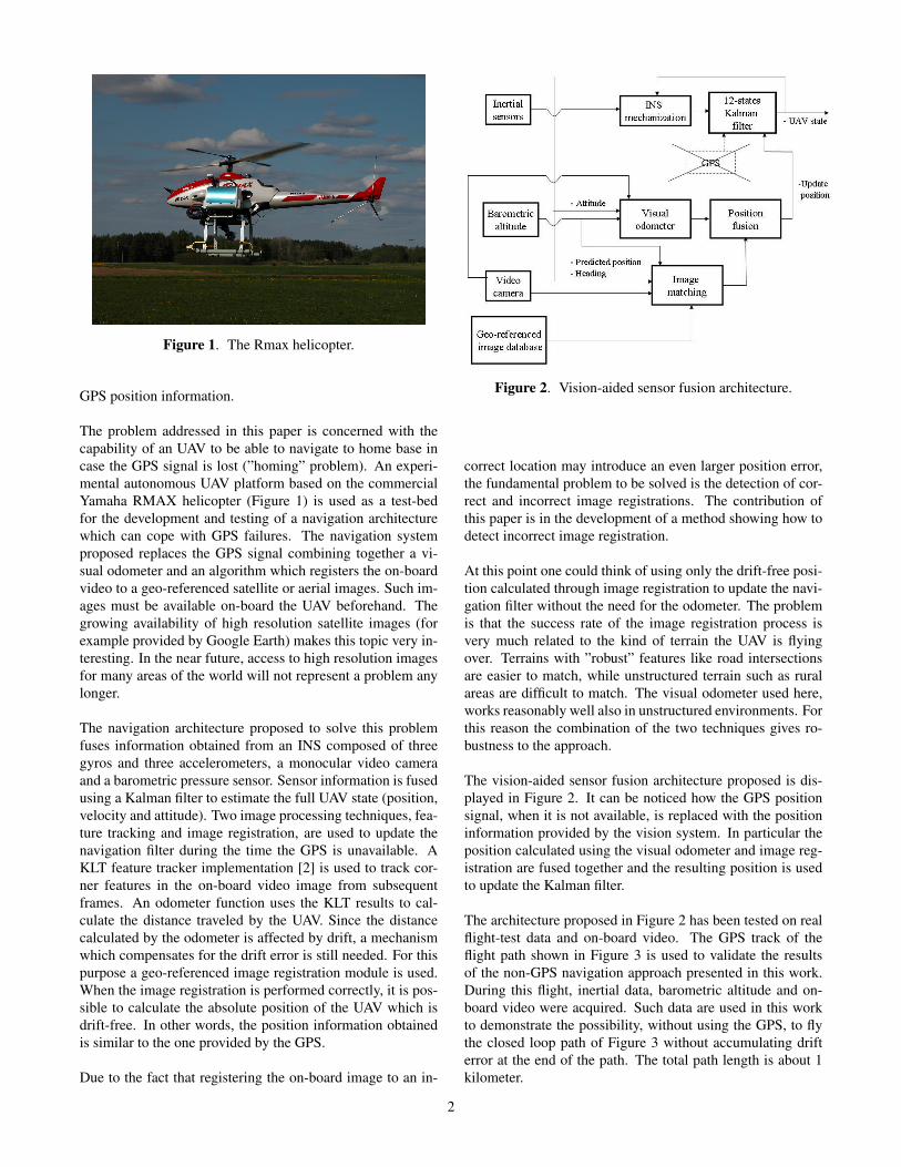
Figure 1. The Rmax helicopter.
GPS position information.
The problem addressed in this paper is concerned with thecapability of an UAV to be able to navigate to home base incase the GPS signal is lost (”homing” problem). An experi-mental autonomous UAV platform based on the commercialYamaha RMAX helicopter (Figure 1) is used as a test-bedfor the development and testing of a navigation architecturewhich can cope with GPS failures. The navigation systemproposed replaces the GPS signal combining together a vi-sual odometer and an algorithm which registers the on-boardvideo to a geo-referenced satellite or aerial images. Such im-ages must be available on-board the UAV beforehand. Thegrowing availability of high resolution satellite images (forexample provided by Google Earth) makes this topic very in-teresting. In the near future, access to high resolution imagesfor many areas of the world will not represent a problem anylonger.
The navigation architecture proposed to solve this problemfuses information obtained from an INS composed of threegyros and three accelerometers, a monocular video cameraand a barometric pressure sensor. Sensor information is fusedusing a Kalman filter to estimate the full UAV state (position,velocity and attitude). Two image processing techniques, fea-ture tracking and image registration, are used to update thenavigation filter during the time the GPS is unavailable. AKLT feature tracker implementation [2] is used to track cor-ner features in the on-board video image from subsequentframes. An odometer function uses the KLT results to cal-culate the distance traveled by the UAV. Since the distancecalculated by the odometer is affected by drift, a mechanismwhich compensates for the drift error is still needed. For thispurpose a geo-referenced image registration module is used.When the image registration is performed correctly, it is pos-sible to calculate the absolute position of the UAV which isdrift-free. In other words, the position information obtainedis similar to the one provided by the GPS.
Due to the fact that registering the on-board image to an in-
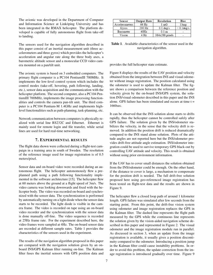
Figure 2. Vision-aided sensor fusion architecture.
correct location may introduce an even larger position error,the fundamental problem to be solved is the detection of cor-rect and incorrect image registrations. The contribution ofthis paper is in the development of a method showing how todetect incorrect image registration.
At this point one could think of using only the drift-free posi-tion calculated through image registration to update the navi-gation filter without the need for the odometer. The problemis that the success rate of the image registration process isvery much related to the kind of terrain the UAV is flyingover. Terrains with ”robust” features like road intersectionsare easier to match, while unstructured terrain such as ruralareas are difficult to match. The visual odometer used here,works reasonably well also in unstructured environments. Forthis reason the combination of the two techniques gives ro-bustness to the approach.
The vision-aided sensor fusion architecture proposed is dis-played in Figure 2. It can be noticed how the GPS positionsignal, when it is not available, is replaced with the positioninformation provided by the vision system. In particular theposition calculated using the visual odometer and image reg-istration are fused together and the resulting position is usedto update the Kalman filter.
The architecture proposed in Figure 2 has been tested on realflight-test data and on-board video. The GPS track of theflight path shown in Figure 3 is used to validate the resultsof the non-GPS navigation approach presented in this work.During this flight, inertial data, barometric altitude and on-board video were acquired. Such data are used in this workto demonstrate the possibility, without using the GPS, to flythe closed loop path of Figure 3 without accumulating drifterror at the end of the path. The total path length is about 1kilometer.
2

Figure 3. GPS track of the UAV flight path used for theexperiment.
2. RELATED WORK
Many research groups are dealing with non-GPS navigationproblems. One technique which could be applied to this kindof problems is the so called Simultaneous Localization andMapping (SLAM). The goal of SLAM is to localize a robotin the environment while mapping it at the same time. Priorknowledge of the environment is not required. AlthoughSLAM is becoming a standard technique for indoor roboticapplications, it still represents a challenge when applied tolarge outdoor environments. A rich literature is available onthis topic [3], [4], [5], [6]. Some examples of SLAM appliedto aerial vehicles can be found in [7], [8].
Compared to the navigation approach used in this paper, theSLAM technique has the advantage of not requiring any a pri-ori maps of the environment. On the other hand, the SLAMapproach makes sense when robots have to close loops, inother words, the robot has to come back to previously visitedlandmarks in order to decrease the position uncertainty. Thiscould be a potential limiting factor for UAV applications. Ifa UAV has lost its GPS signal, probably the best navigationstrategy is the one which minimizes the risk of crashing inpopulated areas. It is possible that flying back home usingpreviously visited sites is not the safest strategy, while fly-ing different routes might be more preferable. For this reasonwe think that a navigation functionality based on aerial im-age matching has great potential for this application and givesmore flexibility as regards choosing emergency flight routesin case of GPS failure.
An application similar to the one described in this paperwhich uses aerial image matching for aircraft position es-timation can be found in [9]. Here the authors try to esti-mate an aircraft position through matching a sequence of on-board images to a geo-referenced image. The on-board im-ages are taken from a downward looking camera mounted ona manned aircraft. A matching method which uses the Haus-
dorff distance is investigated.
There also exists other kinds of terrain navigation methodswhich are not based on aerial images but on terrain eleva-tion models. In this case a measurement of the flight altituderelative to the ground is required. Matching the ground ele-vation profile, measured with a radar altimeter for example,to an elevation database allows for aircraft localization. Anapplication of this method can be found in [10]. The local-ization system has been implemented successfully on somemilitary jet fighters. In the case of UAVs and more specifi-cally for unmanned helicopters, this method does not appearto be appropriate. Compared to jet fighters, UAV helicoptersfly short distances at very low speed so the altitude variationfor such flying platforms is quite poor in terms of allowingground profile matching.
3. SYSTEM DESCRIPTION
The vision-aided sensor fusion architecture tested in thiswork is composed of several modules (see Figure 2). A tra-ditional Kalman filter is used to fuse an INS sensor (3 ac-celerometers and 3 gyros) with a position sensor (vision sys-tem in this case).
An INS mechanization function performs the time integra-tion of the inertial sensors while the Kalman filter functionestimates the INS errors. The errors estimated by the Kalmanfilter are then used to correct the INS solution. The Kalmanfilter implemented uses 12 states. 3 dimensional position er-ror, 3 dimensional velocity error, 3 attitude angle error (pitch,roll, heading) and 3 accelerometer biases. The Kalman filteruses the position update from the vision system to estimatesuch errors.
As mentioned before the vision system combines two tech-niques to calculate the position of the UAV: visual odometerand image registration. The next two sections describe animplementation of the two methods in details. Both odome-ter and image registration calculate the UAV position. Theodometer delivers 4Hz position update. The position updatecalculated from the image registration algorithm occurs onlywhen a reliable matching is found. The method developedto discriminate between reliable and unreliable matching isdescribed in section 5.
When a reliable position update from the image registrationmodule is not available, the output from the visual odometeris directly taken to update the filter. When a reliable imageregistration is obtained, usually it produces a position jumpwhen compared to the position calculated from the odometer.Such position discontinuity can be large especially when thetime elapsed between two valid registrations is large. For thisreason, the Kalman filter cannot be updated directly with theposition calculated from the image registration module, therisk would be the generation of instabilities. The registrationupdate is then introduced gradually over time and it is treatedas a correction added to the odometer solution.
3

4. VISUAL ODOMETER
The visual odometer developed in this work is based on theKLT feature tracker. The KLT algorithm tracks point fea-tures from two subsequent frames [2]. The algorithm selectsa number of features in an image according to a ”goodness”criteria described in [11]. Then it tries to re-associate thesame features in the next image frame. The association isdone by a minimization of a sum of squared differences cri-teria over patches taken around the features in the first image.This association criteria gives very good results when the fea-ture displacement is not too large. Therefore it is importantthat the algorithm has a low execution time. The faster thealgorithm is, the more successful is the association process.The KLT algorithm is very efficient and can run at 20-30Hz.
In this application 50 features in the image are tracked. Oncethe features are detected in the image frame, they are pro-jected onto the real world using Equation 1:
Pn = Rnc
x/fx
y/fy
1
d (1)
where Rnc is the transformation matrix between the camera
frame (c) and the helicopter navigation frame (n). x and yrepresent the pixel position of the feature being tracked in theimage plane. fx and fy are the focal lengths of the camera inthe x and y directions. d is the feature depth.
The navigation frame is a local geodetic frame which has itsorigin coinciding with that of the INS sensor with the Xn axispointing toward the geodetic north, the Zn axis orthogonal tothe reference geodetic ellipsoid pointing down, and the Y n
axis completing a right-handed orthogonal frame. The trans-formation matrix Rn
c is composed by a sequence of rotationswhich take into account the camera orientation relative to theUAV body and the UAV attitudes (the UAV attitude anglesare taken from the Kalman filter as it is shown in Figure 2).Details on the definition of the different reference frames andcoordinate transformation from the camera to the navigationframe can be found in [12].
Since the camera in the experiment presented here is lookingperpendicular downward, the feature depth d is assumed to beequal to the UAV altitude relative to the ground. The depth isthen calculated using a barometric pressure sensor (the atmo-spheric pressure at the ground level is taken before take-off,then the differential pressure during flight can be convertedinto ground altitude). This way of calculating the groundaltitude works if the ground is essentially flat. The flatnessassumption can be removed by a direct measurement of theground altitude. For this purpose our group is investigatingthe possibility of using a radar or laser altimeter on-board theUAV. There are also other methods to estimate the groundaltitude. One way is to use passive vision (downward look-
Figure 4. Visual odometer between two consecutive UAVpositions.
ing camera). Several works have shown that this is possibleachieving good accuracy [13], [14].
Figure 4 represents the UAV observing the same feature(which will be addressed with the j index) from two differentlocations. The UAV displacement ∆Pe relative to an Earth-fixed reference frame (e) and calculated using the feature j,is given by Equation 2:
∆Pej = Pn
j,2 −Pnj,1
= Rnc2
xj,2/fx
yj,2/fy
1
d2 −Rnc1
xj,1/fx
yj,1/fy
1
d1 (2)
The Earth-fixed reference frame (e) has the same orientationof the navigation frame (n) but it is fixed relative to the Earth.
The UAV displacement between two subsequent frames iscalculated by averaging the displacement of all the featurestracked in the image. The resulting averaged displacement isthen:
∆Peavg =
1nfeat
nfeat∑j=1
∆Pej (3)
where nfeat is the number of features tracked. In the experi-ment described in this paper 50 features were tracked in eachframe.
Finally, the position at a certain time t calculated by theodometer function is:
4

P(t) = P(t0) +∑
t
∆Peavg(t) (4)
where P(t0) is the position at time t0 when the last usefulGPS reading was available. As is shown in Figure 2, theposition calculated from the odometer is used to update thenavigation filter.
Experimental results show that the visual odometer alonecombined with the INS gives drift-free velocity and attitudeestimation (it would not be possible using only the INS). Thismeans that once the GPS is lost the UAV can still be con-trolled using proper attitude and velocity information. Thisresult is obtained without image registration, i.e. withoutusing any given information of the environment. The posi-tion uncertainty grows though. The next section describes thetechnique used to solve this problem.
5. IMAGE REGISTRATION
The image registration technique developed here is based onedge matching. A Sobel edge detector is applied to both thegeo-referenced image and the image taken from the on-boardvideo camera. The choice of using edge features derives fromthe fact that edges are quite robust to environmental illumina-tion changes. The geo-referenced and the video camera im-age are generally taken at different times, it can be monthsor years, it has to be expected that the illumination conditionswill differ. Therefore, it is necessary to choose features whichare robust to illumination changes.
Another important factor to be considered is the altitude ofthe UAV from the ground. The higher the UAV flies the morestructure from the environment can be captured. The conse-quence of this is that image registration is more reliable athigher altitude. Another challenge lies in the fact that theenvironment changes over time. It can be that a referenceimage is obsolete after some time due to the change in theenvironment. Considering that small details change quite fast(e.g. car moving on the road) while large structures tend to bemore static (e.g. roads, buildings...), flying at higher altitudemakes the registration more robust to small dynamic changesin the environment.
The image registration process is represented in the block dia-gram in Figure 5. After the on-board color image is convertedinto gray scale, a median filter is applied. The filter is appliedin order to remove small details which are visible from the on-board camera but not visible from the reference image. Themedian filter, has the well-suited property of removing smalldetails while preserving the edges sharp. After filtering, theSobel edge detector is applied. The image is then scaled andaligned to the reference image. Scaling is performed con-verting the on-board image to the resolution of the referenceimage. The scale factor s is calculated using Equation 5 andit is different in x and y direction of the image plane since the
Figure 5. Image registration schematic.
on-board images used do not have squared pixels:
(sx
sy
)=
(1fx1fy
)d • Ires (5)
d, as for the odometer, is the ground altitude given by thepressure sensor and Ires is the resolution of the reference im-age. The alignment of the on-board image with the referenceimage is done using the heading information estimated by thefilter.
The reference image is processed as follows. It is convertedinto gray scale and the Sobel edge detector is applied. This isdone only at the beginning, the resulting edge image is thenkept in memory and used during the visual navigation. TheUAV position predicted by the Kalman filter (Figure 2) is usedas the center of a restricted search area in the reference image.The purpose is to disregard areas of the image too far fromthe estimated UAV position. Since the position uncertaintygrows when there is no update from the registration process,also the search area should grow in the same way. This isnot implemented yet in the system, the experimental resultswhich will be presented later are obtained using a fixed sizeuncertainty window.
After both images have been processed as explained above,a matching algorithm tries to find the position in the croppedreference image which gives the best match with the videocamera image. The position that results the greatest numberof overlapping pixels between the edges of the two imagesis taken as matching result. The matching criteria used, al-though quite simple, give a reasonable success rate. More-over, it can be used for on-line applications. The registrationalgorithm described runs at around 1Hz on a normal laptopcomputer. A screen shot which shows how the two images
5

Figure 6. Processing and matching of the geo-referencedimage and of the on-board image.
are processed and then matched is shown in Figure 6.
Once the matching is obtained the on-board image can begeo-referenced and the absolute position of the UAV can becalculated. The most difficult part is to decide whether totake the position as a good match or not. In other words, ithas to be detected whether the matching is an outlier and thenrejected or can be used to update the filter. The outlier de-tection is not an easy matter since there are areas where theoutliers are predominant compared to the good matches. Oneidea would be to segment the reference image and assign dif-ferent matching probability values for different areas. Priorknowledge can be applied in this process. For example, itis known that image registration in urban areas is more re-liable than in rural areas, or that road intersections result inmore stable matching than road segments. By doing this adifferent degree of uncertainty can be assigned to the match-ing based on the location where the match has occurred. Theuncertainty can then be used to update the navigation filter.This method would require a huge amount of off-line imagepreprocessing which should be applied to the reference im-age before it could be used and would be unpractical for largeimages.
The outliers detection method applied here does not requireany image preprocessing. It is based on the observation thatin areas where the matching is unreliable, the matched po-sition is very noisy. While in areas where the matching isreliable, the position noise decreases. The rejection criteriaapplied is based on the analysis of the position difference be-tween the predicted position coming from the filter and theposition given by the matching algorithm. This difference,when the algorithm is matching the right location, is usuallyquite constant with a low noise level. The outlier rejectionmethod implemented is based on the standard deviation anal-ysis of such a difference. The standard deviation is calculatedover a sliding time window of a fixed size. The algorithmanalyzes the position difference of for example the last 30matching results and if the standard deviation is below a cer-
Figure 7. Detection of a good match.
tain threshold, the averaged position in such time window istaken as good match. If the standard deviation is above thethreshold the matched position is rejected.
Figure 7 shows how this method has the potential for detect-ing good matches. In the upper part of Figure 7 there is a pic-ture of an area where a good match was detected (big picture)and a picture of an on-board camera view (small picture). Inthe lower part of Figure 7, the time history of the differencebetween the predicted position and the matched position isdepicted. The standard deviation of the position differencecalculated using a sliding window with the last 30 matches isshown at the bottom of the picture. It can be observed thatwhen the match becomes stable the standard deviation drops.A good choice of threshold value and size of the sliding win-dow is essential for the success of the method.
6. UAV PLATFORM
The algorithm proposed has been tested using flight-test datacollected from an autonomous UAV helicopter. The heli-copter is based on a commercial Yamaha RMAX UAV heli-copter (Figure 1). The total helicopter length is 3.6 m (includ-ing main rotor). It is powered by a 21 hp two-stroke engineand it has a maximum take-off weight of 95 kg.
6
The avionic was developed in the Department of Computerand Information Science at Linkoping University and hasbeen integrated in the RMAX helicopter. The platform de-veloped is capable of fully autonomous flight from take-offto landing.
The sensors used for the navigation algorithm described inthis paper consist of an inertial measurement unit (three ac-celerometers and three gyros) which provides the helicopter’sacceleration and angular rate along the three body axes, abarometric altitude sensor and a monocular CCD video cam-era mounted on a pan/tilt unit.
The avionic system is based on 3 embedded computers. Theprimary flight computer is a PC104 PentiumIII 700MHz. Itimplements the low-level control system which includes thecontrol modes (take-off, hovering, path following, landing,etc.), sensor data acquisition and the communication with thehelicopter platform. The second computer, also a PC104 Pen-tiumIII 700MHz, implements the image processing function-alities and controls the camera pan-tilt unit. The third com-puter is a PC104 Pentium-M 1.4GHz and implements high-level functionalities such as path-planning, task-planning, etc.
Network communication between computers is physically re-alized with serial line RS232C and Ethernet. Ethernet ismainly used for remote login and file transfer, while seriallines are used for hard real-time networking.
7. EXPERIMENTAL RESULTS
The flight data shown were collected during a flight-test cam-paign in a training area in south of Sweden. The resolutionof the reference image used for image registration is of 0.5meters/pixel.
Sensor data and on-board video were recorded during an au-tonomous flight. The helicopter autonomously flew a pre-planned path using a path following functionality imple-mented in the software architecture [15]. The helicopter flewat 60 meters above the ground at a flight speed of 3m/s. Thevideo camera was looking downwards and fixed with the he-licopter body. The video was recorded on-board and synchro-nized with the sensor data. The synchronization is performedby automatically turning on a light diode when the sensor datastarts to be recorded. The light diode is visible in the cam-era frame. The video is recorded on tape using an on-boardvideo recorder and the synchronization with the sensor datais done manually off-line. The video sequence is recordedat 25Hz frame rate. For the experiment described here, thevideo frames were sampled at 4Hz. The on-board sensor dataare recorded at different sample rates. Table 1 provides thecharacteristics of the sensors used in the experiment.
The results of the navigation algorithm proposed in this paperare compared with the navigation solution given by an on-board INS/GPS Kalman filter running on-line. The Kalmanfilter fuses the inertial sensors with GPS position data and
Table 1. Available characteristics of the sensor used in thenavigation algorithm.
provides the full helicopter state estimate.
Figure 8 displays the results of the UAV position and velocityobtained from the integration between INS and visual odome-ter without image registration. The position calculated usingthe odometer is used to update the Kalman filter. The fig-ure shows a comparison between the reference position andvelocity given by the on-board INS/GPS system, the solu-tion INS/visual odometer described in this paper and the INSalone. GPS failure has been simulated and occurs at time t =1660sec.
It can be observed that the INS solution alone starts to driftsrapidly, thus the helicopter cannot be controlled safely afterGPS failure. The solution given by the INS/odometer sta-bilizes the velocity, in the sense that the velocity drift is re-moved. In addition the position drift is reduced dramaticallycompared to the INS stand alone solution. Plots of the atti-tude angles are not reported here but the INS/odometer pro-vides drift-free attitude angle estimation. INS/odometer inte-gration could be used to survive temporary GPS black-out bycontrolling UAV attitude and velocity. This result is obtainedwithout using prior environment information.
If the UAV has to cover small distances the solution obtainedfrom the INS/odometer could be enough. On the other hand,if the distance to cover is large, a mechanism to compensatefor the position drift is needed. The full drift-free solutionproposed here using geo-referenced image registration hasbeen tested on flight-test data and the results are shown inFigure 9.
The helicopter flew a closed loop path of around 1 kilometerlength. GPS failure was simulated after few seconds from thestarting point. From this point, the drift-free vision systemusing odometer and image registration replaces the GPS inthe Kalman filter. The dashed line represents the flight pathmeasured by the GPS while the continuous line representsthe solution given by the vision-aided navigation scheme de-scribed in this paper and represented in Figure 2. The visualodometer and the image registration module run in parallel.As discussed in section 3, when an update from the imageregistration is available, it usually gives a position disconti-nuity compared to the odometer. Introducing a position jumpin the Kalman filter could cause instability problems. In or-der to avoid this problem, the update correction from the im-age registration is introduced gradually over time. Figure 9
7

Figure 8. Integration of the odometer and INS without using image registration. Prior knowledge of the environment has notbeen used yet.
shows that after the GPS failure the position begins to drift.This means that the image matching has not detected a stablematch. The choice of the standard deviation threshold wasset to 1.4 meters. The first stable match detected was approx-imately at the first road intersection. It can be noticed that thehelicopter position begins to return on the actual path flownby the helicopter. The second stable match was detected al-most at the end of the path. The drift correction is introducedin the navigation system and the final position error at theend of the path is around 3 meters. Other features during thepath were matched correctly but they were not stable enoughto be taken as position update. This experiment shows thateven only few good matches are enough to compensate forthe position drift.
8. CONCLUSIONS AND FUTURE WORK
The experimental vision-aided navigation system architecturedescribed in this paper has the potential to provide a drift-freenavigation solution. The results presented are quite encour-aging although more tests are needed in order to fine tune themethod. It is essential also to collect data from different kindof terrains in order to exploit the potential of the method.
In the future experiments a wide angle camera lens will betested. The one used here was of 45 degrees. We expect thatusing a wide angle lens will improve the image registrationrobustness as a larger part of the environment structure can
be captured in the image. A radar altimeter will also be inte-grated in the helicopter in order to provide direct ground alti-tude measurement. In this way the flat world assumption canbe removed. Another interesting investigation which will bedone in the future is to verify the possibility of using satelliteimages from Google Earth. The interesting part is that theyare available and for free. Google Earth contains an enormousamount of information and in the future it is not unlikely thatthey could be used to navigate UAVs.
ACKNOWLEDGMENTS
This work is supported in part by the National AeronauticsResearch Program NFFP04-S4202 and the Swedish Founda-tion for Strategic Research (SSF) Strategic Research CenterMOVIII.
I would also like to acknowledge my colleague Maria Hempelfor reading this paper and giving useful comments.
REFERENCES
[1] T. Merz, S. Duranti, and G. Conte, “Autonomous land-ing of an unmanned aerial helicopter based on visionand inertial sensing,” in Proc. of the 9th InternationalSymposium on Experimental Robotics, 2004.
[2] C. Tomasi and T. Kanade, “Detection and tracking of
8

Figure 9. Vision-aided navigation experiment using image registration for position drift compensation.
point features,” Carnegie Mellon University, Tech. Rep.CMU-CS-91-132, April 1991.
[3] T. Bailey and H. Durrant-Whyte, “Simultaneous local-ization and mapping (SLAM): Part II,” IEEE Robotics& Automation Magazine, vol. 13, no. 3, pp. 108–117,Sep. 2006.
[4] H. Durrant-Whyte and T. Bailey, “Simultaneous local-ization and mapping (SLAM): Part I,” IEEE Robotics &Automation Magazine, vol. 13, no. 2, pp. 99–110, Jun.2006.
[5] S. Thrun, W. Burgard, and D. Fox, ProbabilisticRobotics, ser. Intelligent Robotics and AutonomousAgents. Cambridge, MA, USA: The MIT Press, 2005.
[6] A. Davison, “Real-Time Simultaneous Localization andMapping with a Single Camera,” in IEEE InternationalConference on Computer Vision, October 2003, pp.1403–1410.
[7] J. Kim and S. Sukkarieh, “Real-time implementationof airborne inertial-slam,” Robot. Auton. Syst., vol. 55,no. 1, pp. 62–71, 2007.
[8] T. Lemaire, C. Berger, I. Jung, and S. Lacroix, “Vision-based slam: Stereo and monocular approaches,” IJCV,vol. 74, no. 3, pp. 343–364, September 2007.
[9] D. G. Sim, R. H. Park, R. C. Kim, S. U. Lee, and I. C.Kim, “Integrated position estimation using aerial im-age sequences,” IEEE Trans. Pattern Anal. Mach. In-tell., vol. 24, no. 1, pp. 1–18, 2002.
[10] N. Bergman, L. Ljung, and F. Gustafsson, “Pointmassfilter and cramer-rao bound for terrain-aided naviga-tion,” in Proc. of the 36th IEEE Conference on Decisionand Control, 1997.
[11] J. Shi and C. Tomasi, “Good features to track,” in IEEEConference on Computer Vision and Pattern Recogni-tion (CVPR’94), Seattle, 1994.
[12] D. B. Barber, J. D. Redding, T. W. McLain, R. W. Beard,and C. N. Taylor, “Vision-based target geo-location us-ing a fixed-wing miniature air vehicle.” Journal of Intel-ligent and Robotic Systems, vol. 47, no. 4, pp. 361–382,2006.
[13] A. Moe, “Passive aircraft altitude estimation using com-puter vision,” Dept. EE, Linkoping University, SE-581 83 Linkoping, Sweden, Lic. Thesis LiU-Tek-Lic-2000:43, September 2000, thesis No. 847, ISBN 91-7219-827-3.
[14] L. Matthies, R. Szeliski, and T. Kanade, “Kalman filter-based algorithms for estimating depth from image se-quences,” Robotics Institute, Carnegie Mellon Univer-
9
sity, Pittsburgh, PA, Tech. Rep. CMU-RI-TR-88-01,January 1988.
[15] G. Conte, “Navigation functionalities for an au-tonomous uav helicopter,” Dept. of Computer and In-formation Science, Linkoping University, SE-581 83Linkoping, Sweden, Lic. Thesis LiU-Tek-Lic-2007:16,March 2007, thesis No. 1307, ISBN 978-91-85715-35-0.
BIOGRAPHY
Gianpaolo Conte is a PhD student atthe Department of Computer and Infor-mation Science, Linkoping University,Sweden. He obtained the Licentiatedegree at the same University and theAerospace Engineering degree at TurinPolytechnic. He is interested in naviga-tion and control problem for UAVs. He
is also working on the development of Micro Aerial Vehiclesplatforms.
Patrick Doherty is a Professor at theDepartment of Computer and Informa-tion Science (IDA), Linkoping Univer-sity (LiU), Sweden. He is director ofthe Artificial Intelligence and IntegratedComputer Systems Division at IDA andhis research interests are in the areaof knowledge representation, automated
planning, autonomous systems, approximate reasoning andUAV technologies.
10