an intech e-edition covering the fundamentals of
TRANSCRIPT

An InTech e-edition covering the fundamentals of automation
Flow & Level
Advanced Tools Simplify Instrument Maintenance
Wireless Level Tracking Propels Brewer’s Success
Back to Basics: Radiometric Level and Density Measurement
The Excitation Frequency of Magnetic Flowmeters
MARCH 2019
2 INTECH FOCUS MARCH 2019 WWW.ISA.ORG
INTECH FOCUS | FLOW
Introduction
INTECH FOCUS | FLOW & LEVEL
The process automation industry is a bastion of innovation today. From digitalization
to new instrumentation, measurement techniques and data collection efforts, these
innovations have driven many organizations to take on ambitious new projects, and
streamline the day-to-day operations in their facility. This is especially true when it comes
to level and flow measurement, as remote calibration, connected instrumentation and
mountains of collected data make the workplace simpler and safer for today’s engineers
and technicians.
Given these rapid advances, the International Society of Automation (ISA) introduces the
inaugural issue of InTech Focus. This in-depth e-resource is designed to inform automation
professionals of the innovations and strategies needed to thrive in tomorrow’s industry, and
make the most out of their flow and level instrumentation. From real-world case studies to
strategic maintenance tips and expert analysis of the new tools, InTech Focus is instrumental
for Process professionals to safely and efficiently enhance the value of their organizations.
3 INTECH FOCUS MARCH 2019 WWW.ISA.ORG
INTECH FOCUS | FLOW INTECH FOCUS | FLOW & LEVEL
5 Advanced Tools Simplify Instrument Maintenance By Jon Dietz, Endress+Hauser
This article describes how end users can exploit advancements in instrumentation to simplify maintenance, reduce parts inventories, and prevent unexpected equipment failures.
11 Wireless Level Tracking Propels Brewer’s Success By Michael Koppelman
Some may find it daunting to take risks and experiment with the new IoT and wireless automation technologies, but it is possible to start small and succeed. The sensors and transmitters gathering operational data are the starting point.
17 Back to Basics: Radiometric Level and Density Measurement By Gene Henry
Modern gamma systems for level or density measurement often work in level and density applications where other solutions will not. End users do need to make sure their supplier is knowledgeable about gamma licensing requirements and can provide full gamma support for their facility.
24 The Excitation Frequency of Magnetic Flowmeters By Scott Stewart
No single flowmeter technology is truly universal. Every flow instrument has its limitations, so every application has to be evaluated carefully to ensure the appropriate process requirements are met. Magmeters are particularly well suited to situations with difficult liquids or where solids tend to cause clogging.
Upcoming Issues: Account Managers:
In This Issue
Richard Simpson+1 [email protected]
Chris Nelson+1 [email protected]
May: Temperature & Pressure
July: Networks
September: Final Control Elements
November: Drives

Do you want to learn more? www.us.endress.com/proline-simply-clever
Customers around the world trust us when it comes to process automation. Our shared goal is plant safety, availability and e� ciency. We are with you every day, everywhere.
People for Process Automation
We understand you need insightful process information to help you run your plant e� ciently.
You make confi dent decisions backed by process data and a complete portfolio of services and solutions to support you.
Do you want to learn more?www.us.endress.com
MEASURED VALUE+ ADDED VALUE
Proline 300/500 - Flow measuring technology for the future
• Added value throughout the entire life cycle of your plant, based on decades of experience in safety-related application
• Entirely developed according to SIL (IEC 61508). Maximized plant safety and availability due to unique features – such as webserver, WLAN, WirelessHART, Industrial Ethernet, or Heartbeat Technology with comprehensive diagnostic and verification functions
• Multifunctional transmitters – combinable with all tried-and-tested Promass and Promag sensors
• Seamless system integration via HART, PROFIBUS PA/DP, FOUNDATION Fieldbus, Modbus RS485, EtherNet/IP and PROFINET
4 INTECH FOCUS MARCH 2019 WWW.ISA.ORG
4
Advanced Tools Simplify Instrument Maintenance
INTECH FOCUS | FLOW & LEVEL
5 INTECH FOCUS MARCH 2019 WWW.ISA.ORG
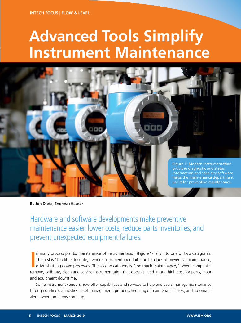
In many process plants, maintenance of instrumentation (Figure 1) falls into one of two categories.
The first is “too little, too late,” where instrumentation fails due to a lack of preventive maintenance,
often shutting down processes. The second category is “too much maintenance,” where companies
remove, calibrate, clean and service instrumentation that doesn’t need it, at a high cost for parts, labor
and equipment downtime.
Some instrument vendors now offer capabilities and services to help end users manage maintenance
through on-line diagnostics, asset management, proper scheduling of maintenance tasks, and automatic
alerts when problems come up.
Figure 1: Modern instrumentation provides diagnostic and status information and specialty software helps the maintenance department use it for preventive maintenance.
By Jon Dietz, Endress+Hauser
Hardware and software developments make preventive maintenance easier, lower costs, reduce parts inventories, and prevent unexpected equipment failures.
6 INTECH FOCUS MARCH 2019 WWW.ISA.ORG
This article describes how end users can exploit these technologies to simplify maintenance, lower
costs, reduce parts inventories, and prevent unexpected equipment failures.
Instrumentation that Diagnoses ItselfSmart flowmeters and other process instruments have been available for years in “smart” versions, pro-
viding vital information for maintenance. For example, 4-20mA HART devices have been available since
the 1980s. HART superimposes 35-40 digital parameters onto the 4-20mA signal, which can include
device status, diagnostic alerts, configuration parameters, and so on. Fieldbus instruments provide much
of the same information through various protocols such as EtherNet/IP and Profibus PA.
Unfortunately, over 60% of instruments are used only to measure the primary process variable, with
the status and diagnostic data ignored by the control system. Maintenance technicians often have to ac-
cess the data with handheld devices that plug into the flowmeter. A lack of understanding, training and
useful software to process the data might account for maintenance departments not taking advantage
of this capability.
Instrument suppliers recognized the problem and have gone to great lengths to equip flowmeters
and other devices with on-board diagnostics, status information and other secondary device parameters
that are needed by maintenance people—and they’ve provided the software needed to make all this
data easily accessible and usable.
For example, flowmeters from Endress+Hauser are typically equipped with Heartbeat Technology,
which provides a wealth of status and diagnostic information, and performs vital functions such as con-
dition monitoring and insitu-verification.
Condition monitoring recognizes if the measurement performance or the integrity of the flowmeter
are impaired. The monitoring values are transmitted to an external condition monitoring system, such as
Endress+Hauser’s PC-based FieldCare software. FieldCare can be used to recognize trends in the second-
ary measured values, and to evaluate relationships among individual parameters.
Legal requirements may call for flowmeters or other instruments to be verified calibrated periodically.
This is normally done by removing the flowmeter from the process, taking it to a flow lab or calibration
rig, and quantitatively comparing it to a traceable standard.
With modern instruments, the flowmeter’s transmitter electronics continuously run a qualitative as-
sessment so all relevant components which influence the device function and integrity are checked. This
confirms and can document by verification that none of the meter components have drifted outside
original calibration tolerances. If the flowmeter calibration frequency can be extended, this represents a
tremendous savings in labor and process down time.
More details can be found in the Flow Control article, “How Flowmeters Perform Self-Verification”
(https://www.flowcontrolnetwork.com/how-flowmeters-perform-self-verification/).
Maintenance ManagementModern instrumentation provides status and diagnostic information, but processing all of this data is of-
ten a problem. For example, a chemical plant in Gendorf, Germany, has more than 4,000 instruments
measuring level, flow, temperature, pressure and other parameters. Having its control systems read all the
diagnostic information from all 4,000 devices, analyze it for problems, and issue instructions to the main-
tenance department would be a daunting problem for the plant’s control system programmers. It would
also burden the control system with data not relevant to its primary task, which is real-time process control.
Instead, instrument manufacturers have developed software packages that perform all those func-
INTECH FOCUS | FLOW & LEVEL
7 INTECH FOCUS MARCH 2019 WWW.ISA.ORG
INTECH FOCUS | FLOW & LEVEL
tions. The packages fall into two basic categories: Instrument management programs, which analyze
real-time information from instrumentation; and asset management software, which keeps track of
every instrument in the plant and stores vital data, such as manuals and parts lists.
Instrument management programs perform several functions to aid maintenance departments, including:
• Configuration—helps maintenance configure new instrumentation during initial installation or when
replacing an existing instrument.
• Condition monitoring—as noted above, used to analyze real-time data coming from instrumentation,
look for problems, and notify the maintenance department when a device needs attention prior to failure.
• Life cycle management—tracks the entire life cycle of an instrument, from initial configuration to
calibrations and repairs, and provides information for audits and safety regulations.
While a particular instrument manufacturer can provide information for its own instruments, what
about all the other instruments in a plant from different manufacturers? Fortunately, standardization
across the instrumentation industry makes that information available.
Device Description (DD), enhanced device description language (EDDL), Device Type Manager (DTM),
and HART and fieldbus configuration files are available from all manufacturers, can be accessed easily
from various web sites, and then loaded into the instrument management program.
Thus, a program like Endress+Hauser’s FieldCare software not only has information about its own in-
struments, it can support over a thousand process instruments and analyzers from other manufacturers.
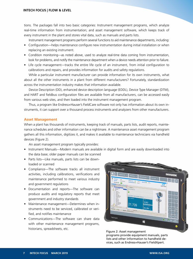
Asset ManagementWhen a plant has thousands of instruments, keeping track of manuals, parts lists, audit reports, mainte-
nance schedules and other information can be a nightmare. A maintenance asset management program
gathers all this information, digitizes it, and makes it available to maintenance technicians via handheld
devices (Figure 2).
An asset management program typically provides:
• Instrument Manuals—Modern manuals are available in digital form and are easily downloaded into
the data base; older paper manuals can be scanned
• Parts lists—Like manuals, parts lists can be down-
loaded or scanned
• Compliance—The software tracks all instrument
activities, including calibrations, verifications and
maintenance performed to meet various industry
and government regulations
• Documentation and reports—The software can
produce audits and regulatory reports that meet
government and industry standards
• Maintenance management—Determines when in-
struments need to be serviced, calibrated or veri-
fied, and notifies maintenance
• Communications—The software can share data
with other maintenance management programs,
historians, spreadsheets, etc.Figure 2: Asset management programs provide equipment manuals, parts lists and other information to handheld de-vices, such as Endress+Hauser’s FieldXpert.

8 INTECH FOCUS MARCH 2019 WWW.ISA.ORG
INTECH FOCUS | FLOW & LEVEL
All this information can be kept on site or in the Cloud, where it can be accessed from a workstation
(Figure 3) or a portable handheld device.
Getting StartedMany plants do not have sufficient information regarding their installed base of process instruments and
analyzers, and over time the plants are modified and instruments change, worsening the situation.
One of the best ways to address this issue is by implementing a maintenance management program,
often with the aid of a major instrument vendor. Most such vendors can come to a process plant, do an
assessment of the instrumentation installed base, and make management recommendations on what
needs to be done to improve the current situation.
For example, Endress+Hauser can perform an Installed Base Analysis, which consists of:
• Instrument inventory—Find and list all on-site devices to enable further transparency, regardless of
manufacturer
• Assess device criticality and maintainability—Define and classify critical measuring points and its maintain-
ability to ensure maintenance tasks can be performed easily and effectively
• Recommend adequate maintenance strategy—Evaluate current maintenance activities and recommend
improvements to achieve a balanced maintenance program
• Identify obsolete equipment—Includes a migration plan to modernize the plant
• Reduce complexity—Includes recommendations to standardize instrumentation and minimize spare parts.
At the completion of the assessment, the instrument vendor will address its recommendations by
providing key information to facilitate relevant decision making regarding the maintenance and quality
improvements, obsolescence and spares management of respective installed base assets. If the plant
agrees, the project begins by implementing the new maintenance program within the scope of a service
agreement. The data describing each instrument is entered into the database and maintained over time
to enable the user to continuously access to an up to date information at any time and from any location.
As noted above, the software may already have most of the data needed, such as DD and DTM files,
manuals, etc. In some cases, old manuals and parts lists may have to be found and scanned in. Eventu-
ally, the data base will be populated
Figure 3: Instrument data from asset management software such as Endress+Hauser’s W@M program can be accessed from workstations or handheld devices.

9 INTECH FOCUS MARCH 2019 WWW.ISA.ORG
INTECH FOCUS | FLOW & LEVEL
A wastewater treatment plant in Thun, Switzerland (Figure 4) had Endress+Hauser conduct an IBA,
and then installed W@M Life Cycle Management software.
Once the data had been recorded, a connection was established to the control system. The visualiza-
tion program allows the plant to quickly identify a measuring device needing attention. The necessary
information can then be quickly accessed, including the right operating manuals, ordering information,
maintenance reports, software drivers and spare parts.
The chemical plant mentioned above also conducted an IBA and adopted such a program to maintain
its 4,000 instruments. In the old days, documents such as calibration reports had to be scanned and filed
manually. Today, this information is available whenever and wherever it is needed. The plant is now able
to identify every one of its devices and react quickly in the event of a malfunction.
Summary
Modern instrumentation and related maintenance strategies are making it much easier for process plants
to perform preventive maintenance, eliminate process shutdowns from failed instruments, and save time
and money by avoiding unnecessary maintenance activities.
Initial implementation of an instrumentation management system can be a daunting task, but instru-
ment vendors can provide assistance as required.
ABOUT THE AUTHORJon Dietz is the national field service manager for Endress+Hauser and has national re-
sponsibility for all after-sale customer field support. He is a U.S. Navy veteran (Advanced
Electronics Program) and prior to joining Endress+Hauser supported Doppler radar ap-
plications within the agricultural industry. Dietz has been with Endress+Hauser for 26
years. He began his career with Endress+Hauser as a field service engineer and has been
in his current position since 1999. Visit us.endress.com for more information.
Figure 4: After an audit, this wastewater treatment plant in Switzerland installed Endress+Hauser’s W@M Life Cycle Management software.

A perfect view – even with condensation!The future is 80 GHz: a new generation of radar level sensors
For the latest generation of radars, condensate on the sensor is not an issue. Totally unaffected by condensation or buildup on the antenna, VEGAPULS 64 accurately detects the liquid level. With the smallest antenna of its kind and exceptional focusing, it delivers outstanding performance every time. Simply world-class!
www.vega.com/radar
Wireless adjustment via Bluetooth with smartphone, tablet or PC. Compatible retrofit to all plics® sensors manufactured since 2002.
11 INTECH FOCUS MARCH 2019 WWW.ISA.ORG
By Michael Koppelman
Wireless Level Tracking Propels Brewer’s Success
The growth of craft brewing has changed the whole American beer paradigm by separating the
market from the traditional “big three.” From 2004 to 2015, annual craft beer and ale production
industry-wide grew fivefold to 25 million barrels, while sales of traditional brews declined.
Craft brewing was born of a do-it-yourself (DIY) countercultural mentality that pushed the boundar-
ies of style, brand, and quality beyond accepted norms. Many of the people making craft beer are not
process engineers, but instead come from a variety of careers and are looking for a different path. Most
have a keen entrepreneurial spirit, an independent streak, and a love of the art of brewing. They come to
craft brewing with different motivations, and think differently than many of their counterparts in other
industries.
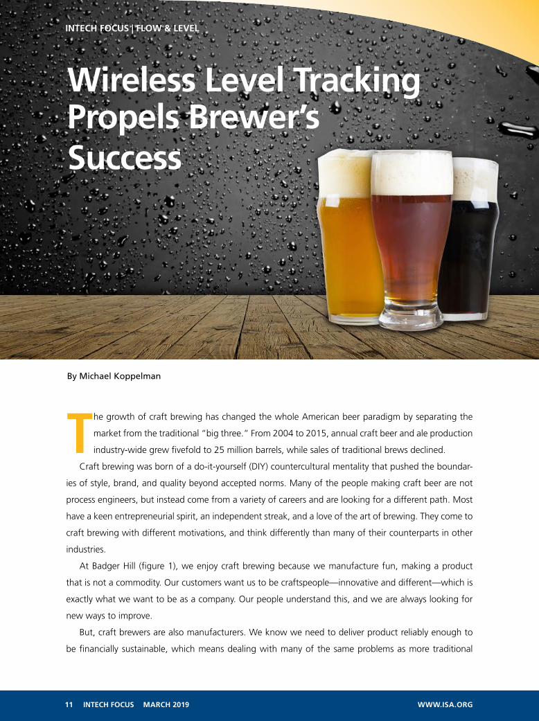
At Badger Hill (figure 1), we enjoy craft brewing because we manufacture fun, making a product
that is not a commodity. Our customers want us to be craftspeople—innovative and different—which is
exactly what we want to be as a company. Our people understand this, and we are always looking for
new ways to improve.
But, craft brewers are also manufacturers. We know we need to deliver product reliably enough to
be financially sustainable, which means dealing with many of the same problems as more traditional
INTECH FOCUS | FLOW & LEVEL

12 INTECH FOCUS MARCH 2019 WWW.ISA.ORG
INTECH FOCUS | FLOW & LEVEL
manufacturers. The expression
of the craft and the capital to in-
novate is made possible through
good manufacturing processes.
Customers expect consistency,
and operations must comply with
appropriate regulations. We need
to learn from other companies, so
we can focus on new problems
rather than ones already solved.
This desire for continuous im-
provement has been a core tenet
at Badger Hill since the beginning.
Each improvement extends our vi-
sion, exposing us to new technol-
ogies and applications. When we
stir in DIY and Internet of Things
(IoT) applications with these technologies, interesting things start to happen.
Some may find it daunting to take risks and experiment with the new IoT and wireless automation
technologies, but it is possible to start small and succeed. The sensors and transmitters gathering opera-
tional data are the starting point. These technologies are scalable, making it easy to start small and grow.
Rolling our own data historian
Badger Hill does not have a traditional supervisory automation system or a process data historian. Like
many craft brewers, ours is largely a manual operation with basic programmable logic controllers driving
motors, valves, and pumps—and only a modest amount of instrumentation. When we installed the first
wireless pressure transmitter, our initial step was to figure out the best way to extract data and post it to
the cloud for analysis and archiving.
This meant getting to know Modbus, an amazingly forward-thinking protocol given its age, which
was not familiar to us. Two wires provide remote data access and automation for dozens of devices. It
can also be extended transparently over TCP/IP. Our first tests did just that using an industrial wireless
gateway that bundled all of the transmitters into a single virtual Modbus network.
As our first experiment, we installed a pressure transmitter on our cold-liquor tank (a brewing water
storage tank) to measure the differential pressure (DP) level and post it to the cloud. Given the low cost
of cloud storage, we started gathering data continuously.
The data is requested by a simple Modbus master hosted on a $20 Arduino-like chip called a Particle
Photon. It reads the response and posts it to a cloud-based database using a RESTful interface over HTTP.
Figure 1: Badger Hill’s people come from a variety of backgrounds, but are all committed to creating innovative products for beer lovers to enjoy.

Figure 2: The scattering in the continuous level plot of the cold-liquor tank showed a steam flow problem in the hotliquor tank. This was one of the first recognitions of the information available through inference from data collected by a Rosemount 3051 wireless pressure transmitter.
13 INTECH FOCUS MARCH 2019 WWW.ISA.ORG
INTECH FOCUS | FLOW & LEVEL
For data analytics, we have pretty graphs on the Internet, and we can download the data for analysis. In
the future, we would like to tap into the big data capabilities of companies like Google or Amazon. New
companies, such as Initial State and Meshify, also exist with this type of application in mind.
We also have Modbus capabilities in our temperature controllers, brewhouse, keg filler, canning line,
and centrifuge. We are slowly bringing more data sources into our analysis. Security is and should be a
concern, but the cloud is no worse, and probably better, than what can generally be achieved in-house
by companies like ours.
Inferring information from data
The interesting part is seeing what information can be inferred from all the data. What can you learn
if you are willing to spend some time looking at the data? Inference provides information on behavior,
which can relate to a person or a process, and generates four main benefits for Badger Hill:
• self-documents human activities by capturing indications of process steps
• creates information useful for training by illustrating current versus ideal practices
• provides secondary and tertiary information on top of primary functions, useful for risk management
• shows where efficiency can be improved through long-term analysis
What does this all mean in actual practice? How did we recognize the potential, and how have we
realized these benefits?
More than just level
The first use of the pressure transmitter was as a DP level instrument on the cold-liquor tank, which is the
initial stage for the fresh water to be used for a new batch. In the initial data (figure 2), there was normal
data scatter, but in some areas, it was much more pronounced. While this might have been written off as
an instrument malfunction, we realized that these areas coincided with feeding steam into the hot-liquor
tank heat exchanger.

Figure 3: Watching the level indications from the hot- and cold-liquor tanks during a brewing process shows each step, documenting overall operation.
14 INTECH FOCUS MARCH 2019 WWW.ISA.ORG
INTECH FOCUS | FLOW & LEVEL
The cold- and hot-liquor tanks are next to each other and have interconnecting pipes. Heating water
in the hot-liquor tank involves feeding steam through a heat exchanger immersed in the water. If too
much steam is being fed into the heat exchanger, steam bubbles form in the water, which shake the tank
and rattle the piping. This shows up on the pressure transmitter mounted on the cold-liquor tank. So,
from this scatter we were able to infer that the steam regulation to the hot-liquor tank heat exchanger
was set incorrectly.
This was an interesting realization, but it became clear that much more was possible when looking at
more complex operations (figure 3). The process of starting a new batch of beer in the hot-liquor tank fol-
lows a set series of steps outlined in the recipe. Usually we try to make two batches, one after the other,
over 20 to 25 hours to use energy more efficiently. The hot- and cold-liquor tanks interact as water needs
to be heated, and the first batch is cooled by transferring its heat to the second batch. The graph shows
the levels on both tanks superimposed with the same time scale. It is easy to see the changes as liquid
moves between the two tanks. By following the profile, it is possible to see each step in the process and
identify changes. So how do we use this information?
These profiles document each step and put the process in a form suitable for comparing it to similar
batches. This provides 90 percent of the information we were recording manually, and provides it in
greater detail. When we lay profiles from multiple brewing days on top of each other (figure 4), we can
see a high degree of consistency with these manual processes. This suggests we have a good recipe, and
our brewers know what they are doing. It also shows us that the process does not need to be adjusted on
the fly, which gives us a basis for plans to automate the process. This allows us to build our craft brewers’
know-how into our automation.

Figure 4: Multiple brewing batches can be compared, illustrating how consistently the recipe can be applied, and how individual brewers approach their craft.
15 INTECH FOCUS MARCH 2019 WWW.ISA.ORG
INTECH FOCUS | FLOW & LEVEL
We manage risk by watching the process in real time. If any values diverge from recognized norms,
we know something is going wrong with the batch.
We can use this information for training as we look at the characteristics of the most effective batches
and most effective brewers. Positive deviations from normal operations can be captured and analyzed, so
we can duplicate improvements.
Making this kind of thing happen is not complex or expensive. It is the result of several technological
approaches working together:
• continuously logging critical process variables, with perpetual data retention using the cloud
• data collection and reporting using small, cheap, replaceable devices with powerful capabilities
• strategically placed process instruments
• the ability to recognize when useful information can be inferred from all the data
The lesson for process engineers is that you should not be afraid of looking for valid inferences. These
are not guesses if they are informed by the data. Data, by itself, does not help. Information comes from
understanding the data and seeing what it is telling you. Insight comes from understanding the informa-
tion, and using it to improve what you are doing to gain competitive advantage.
ABOUT THE AUTHORMichael Koppelman, former head brewer, is currently the CTO of Badger Hill Brewing in
Shakopee, Minn. He is responsible for the technical aspects of brewing the company’s
craft beer, and for other aspects of the company’s operation. Koppelman holds a BS in
astrophysics from the University of Minnesota Twin Cities, and a BA in music from the
Berklee College of Music in Boston.

17 INTECH FOCUS MARCH 2019 WWW.ISA.ORG
INTECH FOCUS | FLOW & LEVEL
By Gene Henry, Endress+Hauser
Radiometric or gamma level/density instruments are most often used in applications where other
measuring techniques fail due to extreme temperatures or pressures, toxic media, complex ge-
ometries of vessels or pipes with difficult installation requirements, high viscosities, changing
fluid behaviors, or abrasive or corrosive properties of the process media.
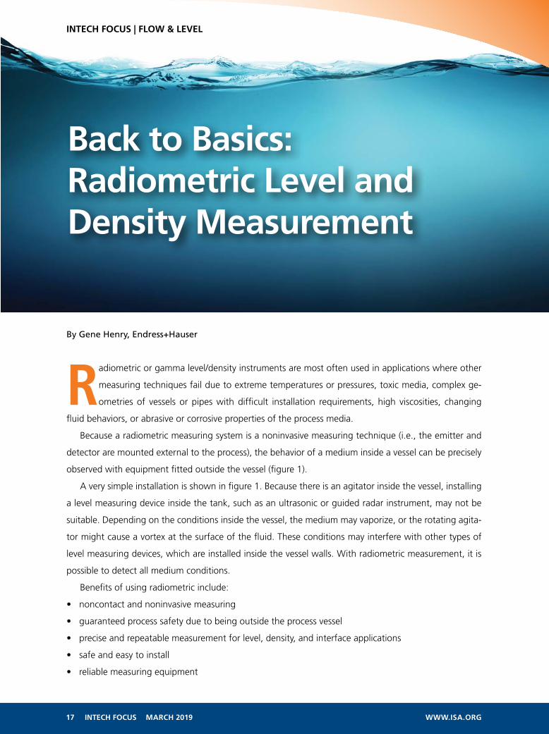
Because a radiometric measuring system is a noninvasive measuring technique (i.e., the emitter and
detector are mounted external to the process), the behavior of a medium inside a vessel can be precisely
observed with equipment fitted outside the vessel (figure 1).
A very simple installation is shown in figure 1. Because there is an agitator inside the vessel, installing
a level measuring device inside the tank, such as an ultrasonic or guided radar instrument, may not be
suitable. Depending on the conditions inside the vessel, the medium may vaporize, or the rotating agita-
tor might cause a vortex at the surface of the fluid. These conditions may interfere with other types of
level measuring devices, which are installed inside the vessel walls. With radiometric measurement, it is
possible to detect all medium conditions.
Benefits of using radiometric include:
• noncontact and noninvasive measuring
• guaranteed process safety due to being outside the process vessel
• precise and repeatable measurement for level, density, and interface applications
• safe and easy to install
• reliable measuring equipment
Back to Basics:Radiometric Level andDensity Measurement

Figure 1: In a radiometric level detection or density measurement system, an external source emits radiation that passes through the vessel and is measured by an external detector.
P = Fa · Fs · Fi
K
18 INTECH FOCUS MARCH 2019 WWW.ISA.ORG
INTECH FOCUS | FLOW & LEVEL
Radioactivity basics
Radioactivity can be roughly classified into
three types, each emitted by the decay of the
radioactive isotope:
• alpha radiation: particle radiation in the
form of a helium nucleon (alpha particle)
• beta radiation: elemental particle radia-
tion in the form of electrons and/or posi-
trons (beta particle)
• gamma radiation: high-energy electro-
magnetic waves similar to radio waves
and light
With radiometric level and density mea-
surement, only gamma radiation is used.
Alpha and beta radiation are not strong
enough to penetrate solid material, but the
high energy and high-frequency wavelength
of gamma waves radiate through material in
the beam’s path.
When a gamma ray passes through matter, the absorption rate is proportional to the thickness of
the layer, the density of the material, the absorption cross section of the material, and the energy of the
wave. Thus, absorption and energy are the main factors that influence the size of the required source and
the quality of radiometric measurement.
Typical industrial isotopes used in radiometric applications are cesium-137 (Cs-137) and cobalt-60
(Co-60). The two isotopes differ in their physical attributes, with cesium having a longer half-life but
lower emitted gamma radiation energy. Cobalt-60 has a shorter half-life with higher energy.
Half-life is the length of time that it takes for the source to decay until it reaches half of the activity
generated by the original isotope. The half-life of Cs-137 is 30.17 years, and Co-60 is 5.2 years. Typically,
Cs-137 is used in industrial applications, because it requires less maintenance (i.e., replacing the sources)
and its activities or strength are sufficient for most applications. In special cases, Co-60 might be required
for radiating through thick material or high-density fluids.
A formula determines the source size, taking into account anything in the beam path (vessel walls,
insulation, heating coils, and obstructions) and the distance from the source to the detector. The calcula-
tion uses the following equation:
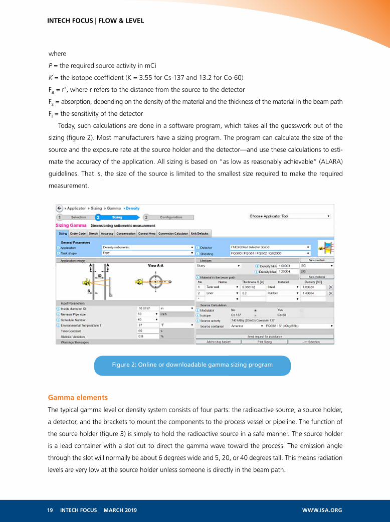
Figure 2: Online or downloadable gamma sizing program
19 INTECH FOCUS MARCH 2019 WWW.ISA.ORG
INTECH FOCUS | FLOW & LEVEL
where
P = the required source activity in mCi
K = the isotope coefficient (K = 3.55 for Cs-137 and 13.2 for Co-60)
Fa = r2, where r refers to the distance from the source to the detector
Fs = absorption, depending on the density of the material and the thickness of the material in the beam path
Fi = the sensitivity of the detector
Today, such calculations are done in a software program, which takes all the guesswork out of the
sizing (figure 2). Most manufacturers have a sizing program. The program can calculate the size of the
source and the exposure rate at the source holder and the detector—and use these calculations to esti-
mate the accuracy of the application. All sizing is based on “as low as reasonably achievable” (ALARA)
guidelines. That is, the size of the source is limited to the smallest size required to make the required
measurement.
Gamma elements
The typical gamma level or density system consists of four parts: the radioactive source, a source holder,
a detector, and the brackets to mount the components to the process vessel or pipeline. The function of
the source holder (figure 3) is simply to hold the radioactive source in a safe manner. The source holder
is a lead container with a slot cut to direct the gamma wave toward the process. The emission angle
through the slot will normally be about 6 degrees wide and 5, 20, or 40 degrees tall. This means radiation
levels are very low at the source holder unless someone is directly in the beam path.
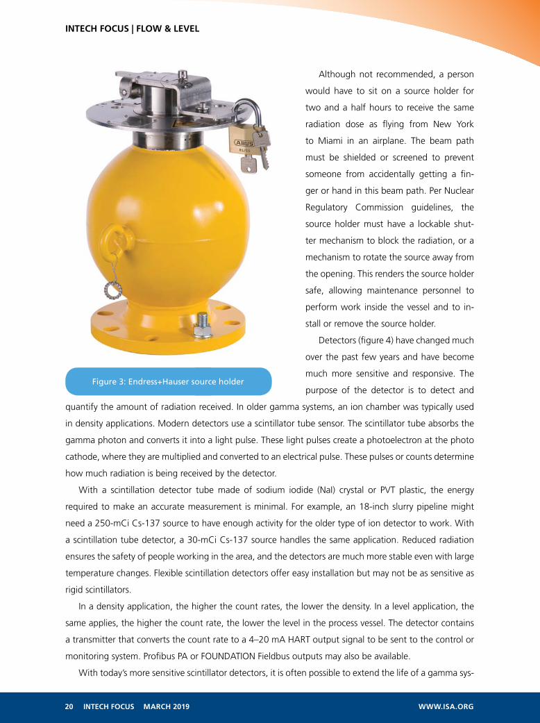
Figure 3: Endress+Hauser source holder
20 INTECH FOCUS MARCH 2019 WWW.ISA.ORG
INTECH FOCUS | FLOW & LEVEL
Although not recommended, a person
would have to sit on a source holder for
two and a half hours to receive the same
radiation dose as flying from New York
to Miami in an airplane. The beam path
must be shielded or screened to prevent
someone from accidentally getting a fin-
ger or hand in this beam path. Per Nuclear
Regulatory Commission guidelines, the
source holder must have a lockable shut-
ter mechanism to block the radiation, or a
mechanism to rotate the source away from
the opening. This renders the source holder
safe, allowing maintenance personnel to
perform work inside the vessel and to in-
stall or remove the source holder.
Detectors (figure 4) have changed much
over the past few years and have become
much more sensitive and responsive. The
purpose of the detector is to detect and
quantify the amount of radiation received. In older gamma systems, an ion chamber was typically used
in density applications. Modern detectors use a scintillator tube sensor. The scintillator tube absorbs the
gamma photon and converts it into a light pulse. These light pulses create a photoelectron at the photo
cathode, where they are multiplied and converted to an electrical pulse. These pulses or counts determine
how much radiation is being received by the detector.
With a scintillation detector tube made of sodium iodide (NaI) crystal or PVT plastic, the energy
required to make an accurate measurement is minimal. For example, an 18-inch slurry pipeline might
need a 250-mCi Cs-137 source to have enough activity for the older type of ion detector to work. With
a scintillation tube detector, a 30-mCi Cs-137 source handles the same application. Reduced radiation
ensures the safety of people working in the area, and the detectors are much more stable even with large
temperature changes. Flexible scintillation detectors offer easy installation but may not be as sensitive as
rigid scintillators.
In a density application, the higher the count rates, the lower the density. In a level application, the
same applies, the higher the count rate, the lower the level in the process vessel. The detector contains
a transmitter that converts the count rate to a 4–20 mA HART output signal to be sent to the control or
monitoring system. Profibus PA or FOUNDATION Fieldbus outputs may also be available.
With today’s more sensitive scintillator detectors, it is often possible to extend the life of a gamma sys-
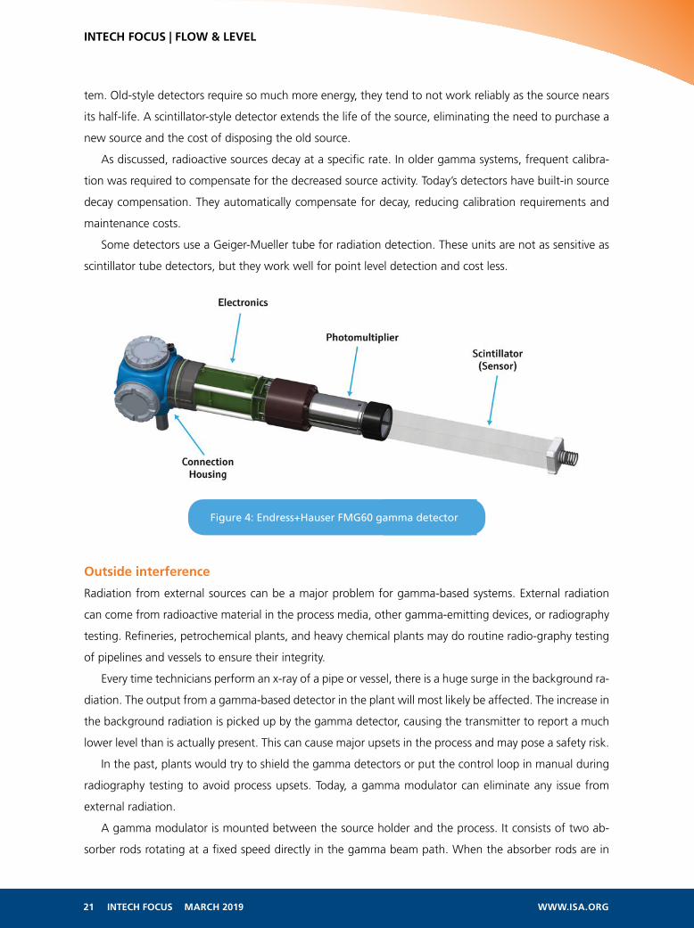
Figure 4: Endress+Hauser FMG60 gamma detector
21 INTECH FOCUS MARCH 2019 WWW.ISA.ORG
INTECH FOCUS | FLOW & LEVEL
tem. Old-style detectors require so much more energy, they tend to not work reliably as the source nears
its half-life. A scintillator-style detector extends the life of the source, eliminating the need to purchase a
new source and the cost of disposing the old source.
As discussed, radioactive sources decay at a specific rate. In older gamma systems, frequent calibra-
tion was required to compensate for the decreased source activity. Today’s detectors have built-in source
decay compensation. They automatically compensate for decay, reducing calibration requirements and
maintenance costs.
Some detectors use a Geiger-Mueller tube for radiation detection. These units are not as sensitive as
scintillator tube detectors, but they work well for point level detection and cost less.
Outside interference
Radiation from external sources can be a major problem for gamma-based systems. External radiation
can come from radioactive material in the process media, other gamma-emitting devices, or radiography
testing. Refineries, petrochemical plants, and heavy chemical plants may do routine radio-graphy testing
of pipelines and vessels to ensure their integrity.
Every time technicians perform an x-ray of a pipe or vessel, there is a huge surge in the background ra-
diation. The output from a gamma-based detector in the plant will most likely be affected. The increase in
the background radiation is picked up by the gamma detector, causing the transmitter to report a much
lower level than is actually present. This can cause major upsets in the process and may pose a safety risk.
In the past, plants would try to shield the gamma detectors or put the control loop in manual during
radiography testing to avoid process upsets. Today, a gamma modulator can eliminate any issue from
external radiation.
A gamma modulator is mounted between the source holder and the process. It consists of two ab-
sorber rods rotating at a fixed speed directly in the gamma beam path. When the absorber rods are in
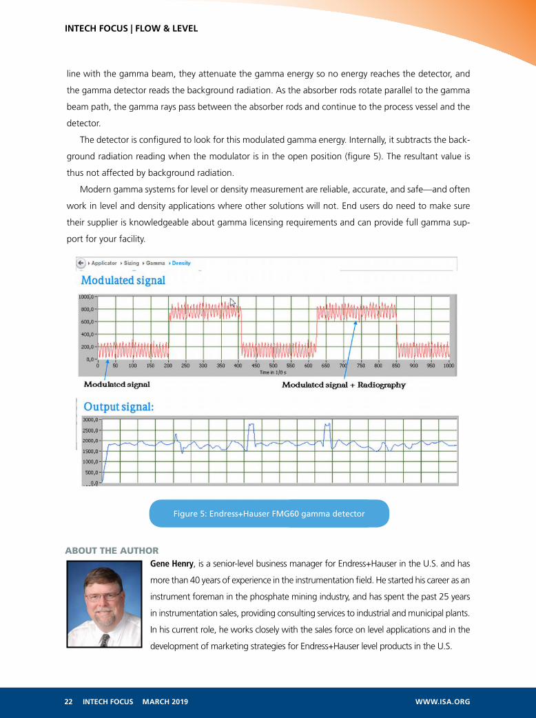
Figure 5: Endress+Hauser FMG60 gamma detector
22 INTECH FOCUS MARCH 2019 WWW.ISA.ORG
INTECH FOCUS | FLOW & LEVEL
line with the gamma beam, they attenuate the gamma energy so no energy reaches the detector, and
the gamma detector reads the background radiation. As the absorber rods rotate parallel to the gamma
beam path, the gamma rays pass between the absorber rods and continue to the process vessel and the
detector.
The detector is configured to look for this modulated gamma energy. Internally, it subtracts the back-
ground radiation reading when the modulator is in the open position (figure 5). The resultant value is
thus not affected by background radiation.
Modern gamma systems for level or density measurement are reliable, accurate, and safe—and often
work in level and density applications where other solutions will not. End users do need to make sure
their supplier is knowledgeable about gamma licensing requirements and can provide full gamma sup-
port for your facility.
ABOUT THE AUTHORGene Henry, is a senior-level business manager for Endress+Hauser in the U.S. and has
more than 40 years of experience in the instrumentation field. He started his career as an
instrument foreman in the phosphate mining industry, and has spent the past 25 years
in instrumentation sales, providing consulting services to industrial and municipal plants.
In his current role, he works closely with the sales force on level applications and in the
development of marketing strategies for Endress+Hauser level products in the U.S.

ONECOMPLETE FLOW ENERGY SOLUTION. Featuring three revolutionary flow meter
technologies made by one company.
Optimized for measuring critical and costly
flows we call Flow Energy: air, natural gas,
water, and steam.
One contact point links you
to Sierra’s global network
of flow energy experts.
Download Flow Energy Guide
THERMALAir / Natural Gas
DESIGNED, BUILT AND CALIBRATED IN CALIFORNIA BY SIERRA
ULTRASONICHot / Chill Water BTU
VORTEXSteam / Liquid / Gas
800.373.0200sierrainstruments.com/flowexpert
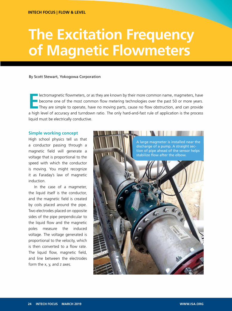
A large magmeter is installed near the discharge of a pump. A straight sec-tion of pipe ahead of the sensor helps stabilize flow after the elbow.
24 INTECH FOCUS MARCH 2019 WWW.ISA.ORG
INTECH FOCUS | FLOW & LEVEL
Electromagnetic flowmeters, or as they are known by their more common name, magmeters, have
become one of the most common flow metering technologies over the past 50 or more years.
They are simple to operate, have no moving parts, cause no flow obstruction, and can provide
a high level of accuracy and turndown ratio. The only hard-and-fast rule of application is the process
liquid must be electrically conductive.
Simple working conceptHigh school physics tell us that
a conductor passing through a
magnetic field will generate a
voltage that is proportional to the
speed with which the conductor
is moving. You might recognize
it as Faraday’s law of magnetic
induction.
In the case of a magmeter,
the liquid itself is the conductor,
and the magnetic field is created
by coils placed around the pipe.
Two electrodes placed on opposite
sides of the pipe perpendicular to
the liquid flow and the magnetic
poles measure the induced
voltage. The voltage generated is
proportional to the velocity, which
is then converted to a flow rate.
The liquid flow, magnetic field,
and line between the electrodes
form the x, y, and z axes.
The Excitation Frequency of Magnetic Flowmeters
By Scott Stewart, Yokogowa Corporation

Figure 1: Magmeter construction is very straightforward. The magnetic flux field (B) is generated by a coil that is mounted perpendicular to what are typically two electrodes. They will pick up the induced electromotive force (voltage). The magnetic field generates an electromotive force proportional to the magnetic flux density (B), the velocity of the conductor (V), and the diameter of the pipe (D).
Magnetic flowmeter sensor construction
25 INTECH FOCUS MARCH 2019 WWW.ISA.ORG
INTECH FOCUS | FLOW & LEVEL
Figure 1 goes into more detail about the actual construction. Magmeter users appreciate how the interior
surface of the device can match the upstream and downstream pipe diameter, and how there are no ob-
structions into the flow stream. The flowmeter itself must have an insulating lining, which can be made
from rubber, Teflon, ceramic, or other materials capable of standing up to erosive or corrosive media.
Magmeters are highly scalable, running from 0.1 inch to 104 inches or more in diameter. They work
well for clean fluids, such as water, acids, and caustics—or in heavy particulate applications, such as pa-
per stock, pulp, and lime slurries. As mentioned earlier, the main requirement is the process media must
have some level of conductivity, with a typical minimum range of 1 micro-Siemen (µS) to 5 µS. As long
as the process meets this requirement, the meter should perform satisfactorily in the application. Most
oil-based liquids are not conductive, which knocks magmeters out of many refinery applications.
The exciting partSince their introduction in the 1950s, magmeters have evolved enormously from a technology stand-
point. A typical meter from the first decade would have used AC to excite the coil, so it used the avail-
able electrical line frequency of 50 Hz or 60 Hz. Users soon found the high sampling rate this frequency
offered to be particularly well suited for noisy slurry applications, and it offered fast response to changes
in flow rate. However, users also noticed these AC-powered magmeters did not have a stable zero point
when there was no flow. If nothing was moving in the line, the devices tended to wander. They also used
a large amount of energy, with many units drawing as much as 300 W.
As magmeter technology advanced, the next generation excited the coils with pulsed square-wave
DC operating around 6.25 Hz to 11 Hz. This worked well enough in most situations and delivered the

Figure 2: Creating a waveform with characteristics of both AC and DC allows a magmeter to use the advantages of both.
Figure 3: Dual-frequency sensors deliver performance advantages without requiring a user to choose one or the other or to switch at various points.
26 INTECH FOCUS MARCH 2019 WWW.ISA.ORG
INTECH FOCUS | FLOW & LEVEL
sought-after zero stability, but lower excitation frequencies could not handle noise caused by a high
solids content. The low sampling rates also made them sluggish when responding to rapidly changing
flow rates.
As new power supply circuits developed, instrumentation designers had more options available to
try different excitation frequencies. This led to adjustable sensors where a user could choose the best
frequency for the application. If the process is noisy with slurries or flow rates change rapidly, the user
chooses a high frequency. For an intermittent process, such as a batch application with periods when
flow stops, the user chooses the low frequency.
This approach works, but as transmitters got smarter, it was possible to incorporate circuitry capable
of using both frequencies simultaneously. Dual-frequency excitation allows the transmitter to superim-
pose two frequencies on top of each other at the same time (figure 2). A low-frequency component of
6.25 Hz and a high-frequency component of 75 Hz work together for higher performance than either
one functioning alone (figure 3).
Reducing power consumptionEarly magmeters needed a powerful magnetic field to create a signal strong enough to be measured
accurately and linearized enough to provide a reliable and accurate flow reading. This is why early units
drew so much power. With improvements in transmitter designs, it became possible to scale everything
down, even while improving performance.
27 INTECH FOCUS MARCH 2019 WWW.ISA.ORG
INTECH FOCUS | FLOW & LEVEL
Units that once drew 300 W can now operate with 10 W to 15 W. Naturally, the physical size of a
sensor has a major influence on power consumption; a 36-inch sensor requires more power to maintain
a magnetic field than a 4-inch sensor. Some designs go even further with power reduction, to the point
where two-wire, loop-powered designs are available in sensor sizes up to 8 inches. Bear in mind, when
only 0.3 W is available (0.1 percent of what earlier units often needed), there is some compromise in
performance.
Nonetheless, being able to replace other loop-powered flowmeters with a magmeter offers compel-
ling advantages. Differential pressure and mechanical flowmeters are still very common, but obstructions
in the flow path can cause clogging and pressure loss. Having the free flow of a magmeter without need-
ing to update wiring is very attractive.
These low-power units have some limitations. Check with your supplier, but they typically require
relatively high conductivity (10 µS to 20 µS) for the process liquid and a slight reduction in accuracy.
Four-wire magmeters are usually capable of accuracies of ±0.2 percent to ±0.5 percent of flow rate.
Loop-powered magmeters usually start at ±0.5 percent of flow. Moreover, four-wire units have a higher
effective turndown ratio, handling liquid velocities ranging from 0.33 feet per second (fps) to 33 fps.
Simple installation requirementsMagmeters have few installation constraints, but observing them goes a long way toward ensuring the
best possible performance. First and foremost is keeping the pipe full of liquid. If long horizontal runs
accumulate slugs of air, this will cause inaccurate readings. Keep the sensor at a low point in the piping,
or better yet, install it in a vertical section with flow going up.
Second, like most flowmeter designs, having straight pipe upstream and downstream from the sen-
sor reduces turbulence and provides more accurate readings. The flow profile through a pipe is never
entirely uniform, but reducing turbulence keeps it more predictable. Having at least five diameters of
straight pipe upstream and at least two diameters downstream will be a major help. Having longer
straight runs is even better.
No single flowmeter technology is truly universal. Every flow instrument has its limitations, so every
application has to be evaluated carefully to ensure the appropriate process requirements are met. Mag-
meters are particularly well suited to situations with difficult liquids or where solids tend to cause clog-
ging, so make sure they are in your application toolbox.
ABOUT THE AUTHORScott Stewart, has been a senior product consultant with Yokogawa Corporation for
11 years, part of a 25-year career in industrial automation. Prior experience includes
10 years with Magnetrol International as a level and flow specialist in the southeast
U.S. He graduated from Texas State University with a degree in marketing. Stewart is
currently training for the Ride the Rockies Bicycle Tour in Colorado and likes to tinker
with classic automobiles.

Continuing its legacy as the market leader in accurate and reliable magnetostrictive level measurement solutions, ABB introduces the new SIL certified LMT Series featuring the industry’s most advanced technology, with built-in waveform and NAMUR compliant diagnostics. Whether you choose the direct insertion (LMT 100) or non-intrusive (LMT 200) solution, you benefit from an easy to apply level measurement solution for your toughest applications. Measurement made easy. abb.com/level
— ABB’s new LMT magnetostrictive level transmitters Easy to apply. Powerful results.