an improved unsteady cfd analysis of plunging airfoils by
TRANSCRIPT
International Journal of Advanced Thermofluid Research Vol. 2, No. 1, 2016 ISSN 2455-1368 (Online) Special Issue of Selected Papers from 2nd International Conference on Computational Methods in Engineering and Health Sciences
(ICCMEH- 2015), 19-20 December 2015, Universiti Putra Malaysia, Selangor, Malaysia.
Published by: International Research Establishment for Energy and Environment (IREEE), Kerala, India. (www.ijatr.org; www.ireee.net)
60
An Improved Unsteady CFD Analysis of Plunging Airfoils by using OpenFoam
P. Srinivasa Murthya* and M.R. Muralidharanb
aAeronautical Development Establishment, Bangalore-560075, INDIA bSupercomputer Education and Research Centre, Indian Institute of Science,
Bangalore-560012, INDIA
*Corresponding Author: E-mail: [email protected]
Phone:+91 9449010056
Abstract: Unsteady Aerodynamics study of Plunging Airfoils at various frequencies and
amplitude at low Reynolds Numbers of the order of Insect/Birds flight is of importance to the
design and flying of Micro Aerial Vehicle to meet the requirement of Para-military forces,
Border Security forces and other homeland service forces. A new methodology has been
developed for the analysis of plunging airfoil based on CFD tool 'OpenFoam'. Since the
experimental data available for NACA 0012 Airfoil is in plunging motion, conditions relevant
to the experiment are chosen for the analysis. As plunging velocity increases there is an
increase in thrust coefficient. Similar trends are observed from experiment and commercial
CFD code, Fluent. However, OpenFoam agreement with experiment is better and comparable
with commercial CFD code. Also from the analysis of NACA 4412 airfoil, it has been found
that Cl, Cd behavior is unimodal at low frequency and multimodal at high frequency plunging
motions.
Keywords: Navier Stokes Solvers, Parallel performance, Plunging airfoil, SnappyhexMesh,
Unsteady flow.
1. Introduction
There are several methods available to analyse unsteady flow starting from analytical
method based on Theodorson (1935) to more complex CFD based Navier Stokes solvers
(Ashraf et al. 2007). At low Reynolds Numbers of the order of insect/birds flight none of the
analytical and quasi-steady methods are useful to predict the flow characteristics which are
quite complex involving flow separation, transition, reattachment and unsteadiness. Hence
CFD methods are the right choice although they are more costly and time-consuming, and
require high performance computing systems. Since open source CFD code ‘OpenFoam’ is
becoming more popular for implementing and evaluating High Performance Computing
systems, GPU performance has been evaluated for bench mark test case and cavity flow
problem, and compared with CPU performance. It has been found by Murthy et al. (2013)
that, GPU performance is 1.7 times faster than CPU performance. Although same set of Navier
Stokes equations are solved in both the Openfoam and Fluent there are subtle differences in
International Journal of Advanced Thermofluid Research Vol. 2, No. 1, 2016 ISSN 2455-1368 (Online) Special Issue of Selected Papers from 2nd International Conference on Computational Methods in Engineering and Health Sciences
(ICCMEH- 2015), 19-20 December 2015, Universiti Putra Malaysia, Selangor, Malaysia.
Published by: International Research Establishment for Energy and Environment (IREEE), Kerala, India. (www.ijatr.org; www.ireee.net)
61
the way numerics are handled; the former is more accurate at the expense of cpu time than
the later. Fluent data are used from Ashraf et al. (2007) for NACA 0012 airfoil analysis. This
paper presents the solution of plunging NACA 0012 Airfoil at low Reynolds Numbers based
on open source CFD code, 'OpenFoam'. The results are compared with the experimental data
of Heathcote et al. (2006) and the Fluent’s predictions of Ashraf et al. (2007).
2. Methods
2.1 Problem Setup and Method of Solution
Two typical airfoils, one symmetric (NACA 0012 airfoil) for which experimental and
numerical data(Fluent) available for validation/comparison and the other cambered (NACA
4412 airfoil) which is a representative for practical applications in terms of designing
camber for desired unsteady lift and drag characteristics are considered. These airfoils are
exposed to plunging motions.
Case Analysed for NACA 0012 Airfoil: Velocity, U =0.2 m/s, Reduced frequency, Non-
dimensional plunging velocity, kh=0.35, 1.0, 1.5, 2.0; Amplitude, h =0.175 m, Reynolds
number, Re =20,000.
Case Analysed for NACA 4412 Airfoil: Velocity, U =50 m/s, frequency, f= 20Hz, 50Hz;
Amplitude= 0.2m, 0.5m; Reynolds number, Re =2500.
Solver: SimpleFoam, Incompressible turbulent flow solver
CPU: 1 to 3 days for one flow simulation for 1.6 sec duration
Grid size: 1, 17,696 cells generated from open source BlockMesh and SnappyHexMesh
which are part of the OpenFoam Library.
2.2 Boundary and Initial conditions
At the inflow boundary, the velocity is specified (velocity Dirichlet boundary condition)
based on the desired Re, and the pressure is restricted to the zero-gradient condition
(Neumann boundary condition). At the outflow boundary, the pressure is set to the
freestream value (Dirichlet boundary condition), while the velocity is set to the zero-
gradient condition (Neumann boundary condition). The far-field boundary is set to
symmetry boundary condition, and is placed at an appropriate distance from the moving
body surface to minimize its undesired effects on the airfoil’s surrounding flow field. The
stationary airfoils are set to no-slip boundary condition with fixed velocity (U = 0) and zero
gradient pressure boundary condition. The unsteady moving airfoils are set to moving wall
velocity boundary condition. This boundary condition guarantees the no-slip boundary
condition by introducing an extra velocity to keep the flux through the moving boundary
equal to zero. The solution of N-S equations also needs the initial fluid properties (velocity,
International Journal of Advanced Thermofluid Research Vol. 2, No. 1, 2016 ISSN 2455-1368 (Online) Special Issue of Selected Papers from 2nd International Conference on Computational Methods in Engineering and Health Sciences
(ICCMEH- 2015), 19-20 December 2015, Universiti Putra Malaysia, Selangor, Malaysia.
Published by: International Research Establishment for Energy and Environment (IREEE), Kerala, India. (www.ijatr.org; www.ireee.net)
62
pressure, kinematic viscosity, k and omega) to be specified at the start of the simulations.
The steady state solutions are used as the initial conditions for the time-marching unsteady
calculations with free stream velocity.
2.3 Turbulence Model
k-omega SST turbulence model is used in the incompressible Reynolds Averaged Navier
Stokes solver.
2.4 New Methodology
A New methodology has been developed by means of numerical experimentation of critical
parameters such as relaxation parameters, relative tolerance level, number of sub iterations,
stability parameters (courant numbers) and smoothing parameters to achieve converged
solution in cases of severe flow gradients. In order to get more accurate unsteady solution
one need to do more rigorous analysis in terms of grid refinement in the region of severe
flow gradients with higher order numerical schemes with better spatial and temporal
accuracy. This requires computationally more intensive computing system with large
memory and high speed.
To study unsteady variations of pressure or entropy in both time and space involves spectral
analysis of pressure at each point on the surface of the airfoil. Since the requirements in time
bound project were to get unsteady characteristics of lift and drag over the airfoil doing
plunging motions, the analysis were confined to gross flow characteristics. Effect of angle of
attack on the unsteady flow characteristics of the airfoils can be considered by imposing
pitching motion over the plunging motion. Combination of pitching and heaving motions are
not considered in this paper. But it will be considered at a later stage as an extension of the
present work.
3. Results and Discussion
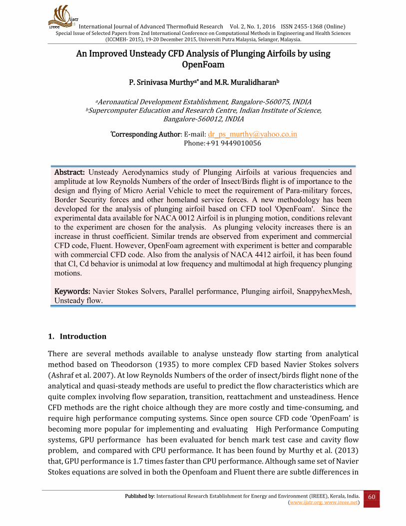
Fig. 1 shows Mean Thrust coefficient versus kh for OpenFoam, Fluent due to Ashraf et al. (2007) and Experiment due to Heathcote et al. (2006). Grid size of 91,001 hexahedral cells was used in Fluent due to Ashraf et al. (2007). Grid size of 1,17,696 hexahedral cells is used in OpenFoam. As flapping velocity increases there is an increase in thrust coefficient. Similar trends are observed from experiment and commercial CFD code, Fluent. However, OpenFoam agreement with experiment is better and comparable with commercial CFD code. The reason could be due to the better grid distribution generated by snappyhexmesh grid generator and the numerical algorithm designed in OpenFoam.
International Journal of Advanced Thermofluid Research Vol. 2, No. 1, 2016 ISSN 2455-1368 (Online) Special Issue of Selected Papers from 2nd International Conference on Computational Methods in Engineering and Health Sciences
(ICCMEH- 2015), 19-20 December 2015, Universiti Putra Malaysia, Selangor, Malaysia.
Published by: International Research Establishment for Energy and Environment (IREEE), Kerala, India. (www.ijatr.org; www.ireee.net)
63
Fig. 1. Time-averaged CT versus kh, NACA0012 Airfoil, U=0.2 m/s, R= 20.000, h=0.175, Grid 1, 17,696 cells.
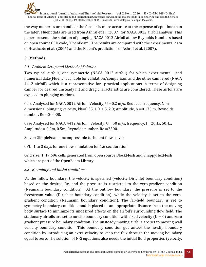
Fig 2 shows Mean Propulsive efficiency versus kh for OpenFoam, Fluent due to Ashraf et al. (2007) and Experiment due to Heathcote et al. (2006). As flapping velocity increases propulsive efficiency decreases. Similar trends are observed from experiment and commercial CFD code Fluent. However, OpenFoam agreement with experiment is better and comparable with commercial CFD code. The reason could be due to the better grid distribution generated by snappyhexmesh grid generator and numerical algorithm designed in OpenFoam.
Fig. 2. ηp (Mean propulsive efficiency ) versus kh (non-dimensional plunging velocity),
NACA0012 Airfoil, U=0.2 m/s, R= 20.000, h=0.175,Grid 1,17,696 cells.
International Journal of Advanced Thermofluid Research Vol. 2, No. 1, 2016 ISSN 2455-1368 (Online) Special Issue of Selected Papers from 2nd International Conference on Computational Methods in Engineering and Health Sciences
(ICCMEH- 2015), 19-20 December 2015, Universiti Putra Malaysia, Selangor, Malaysia.
Published by: International Research Establishment for Energy and Environment (IREEE), Kerala, India. (www.ijatr.org; www.ireee.net)
64
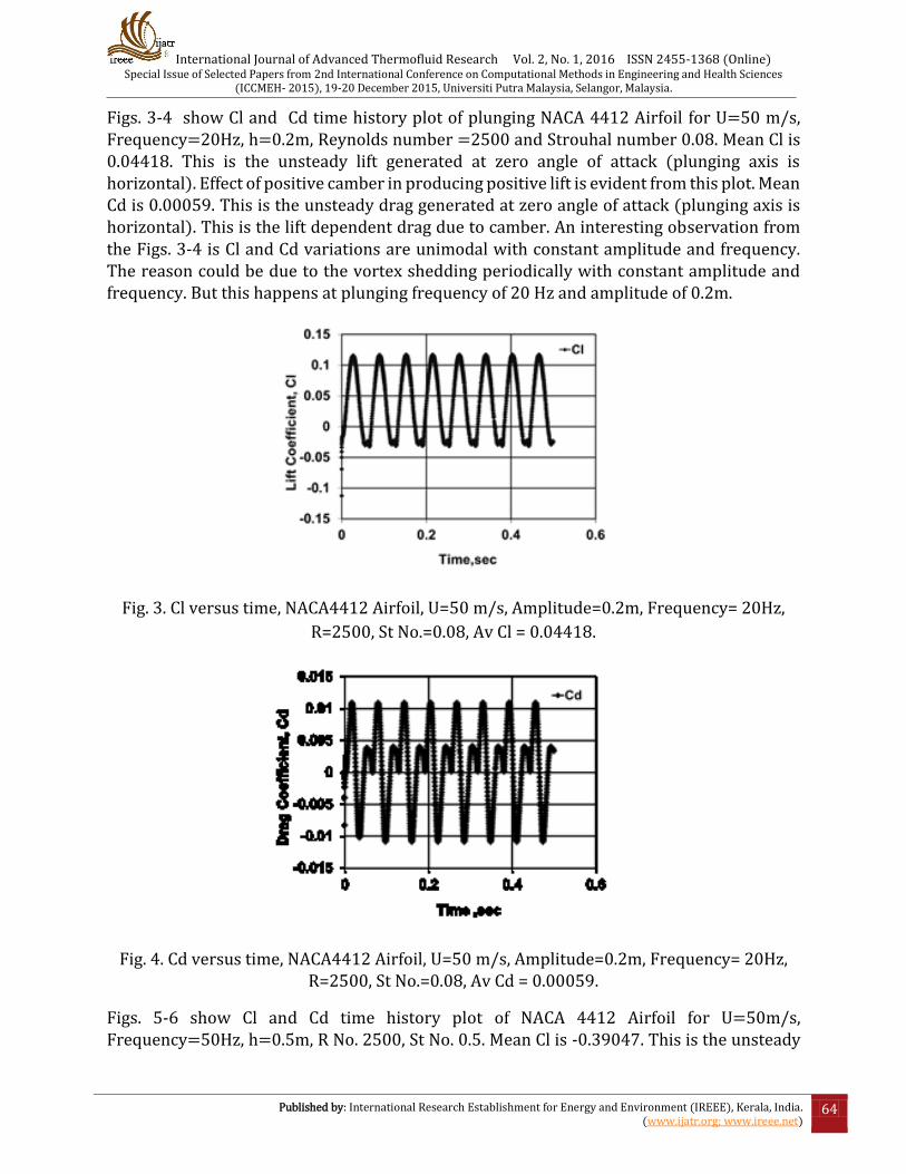
Figs. 3-4 show Cl and Cd time history plot of plunging NACA 4412 Airfoil for U=50 m/s, Frequency=20Hz, h=0.2m, Reynolds number =2500 and Strouhal number 0.08. Mean Cl is 0.04418. This is the unsteady lift generated at zero angle of attack (plunging axis is horizontal). Effect of positive camber in producing positive lift is evident from this plot. Mean Cd is 0.00059. This is the unsteady drag generated at zero angle of attack (plunging axis is horizontal). This is the lift dependent drag due to camber. An interesting observation from the Figs. 3-4 is Cl and Cd variations are unimodal with constant amplitude and frequency. The reason could be due to the vortex shedding periodically with constant amplitude and frequency. But this happens at plunging frequency of 20 Hz and amplitude of 0.2m.
Fig. 3. Cl versus time, NACA4412 Airfoil, U=50 m/s, Amplitude=0.2m, Frequency= 20Hz,
R=2500, St No.=0.08, Av Cl = 0.04418.
Fig. 4. Cd versus time, NACA4412 Airfoil, U=50 m/s, Amplitude=0.2m, Frequency= 20Hz, R=2500, St No.=0.08, Av Cd = 0.00059.
Figs. 5-6 show Cl and Cd time history plot of NACA 4412 Airfoil for U=50m/s, Frequency=50Hz, h=0.5m, R No. 2500, St No. 0.5. Mean Cl is -0.39047. This is the unsteady

International Journal of Advanced Thermofluid Research Vol. 2, No. 1, 2016 ISSN 2455-1368 (Online) Special Issue of Selected Papers from 2nd International Conference on Computational Methods in Engineering and Health Sciences
(ICCMEH- 2015), 19-20 December 2015, Universiti Putra Malaysia, Selangor, Malaysia.
Published by: International Research Establishment for Energy and Environment (IREEE), Kerala, India. (www.ijatr.org; www.ireee.net)
65
lift generated at zero angle of attack (plunging axis is horizontal). Effect of positive camber in producing positive lift is not evident from this plot because of plunging frequency, 50 Hz and amplitude 0.5m. Mean Cd is -0.133. This is the unsteady drag generated at zero angle of attack (plunging axis is horizontal). This is the lift dependent drag due to camber at plunging frequency, 50Hz and amplitude 0.5m. It is to be noticed that Cd is negative which means airfoil is producing thrust at the plunging frequency of 50Hz and amplitude 0.5m An interesting observation from the Figs. 5-6 is Cl and Cd variations are multi-modal with varying amplitudes and frequencies. The reason could be due to the vortices of various sizes shedding periodically with varying amplitudes and frequencies at different instants of time. But this happens at plunging frequency of 50 Hz and amplitude 0.5m. It has been found that at low plunging frequency, Cl and Cd behaviour is uni-modal with constant amplitude. But at high plunging frequency, Cl and Cd behaviour is multi-modal with varying amplitude. This important finding is useful to design cambered airfoil to get the desired unsteady results
Fig. 5. Cl versus time, NACA4412 Airfoil, U=50 m/s, Amplitude=0.5m, Frequency= 50Hz,
R=2500, St No.=0.5, Av Cl = -0. 39047.
Fig. 6. Cd versus time, NACA4412 Airfoil, U=50 m/s, Amplitude=0.5m, Frequency= 50Hz,
R=2500, St No. =0.5, Av Cd = -0.133.
International Journal of Advanced Thermofluid Research Vol. 2, No. 1, 2016 ISSN 2455-1368 (Online) Special Issue of Selected Papers from 2nd International Conference on Computational Methods in Engineering and Health Sciences
(ICCMEH- 2015), 19-20 December 2015, Universiti Putra Malaysia, Selangor, Malaysia.
Published by: International Research Establishment for Energy and Environment (IREEE), Kerala, India. (www.ijatr.org; www.ireee.net)
66
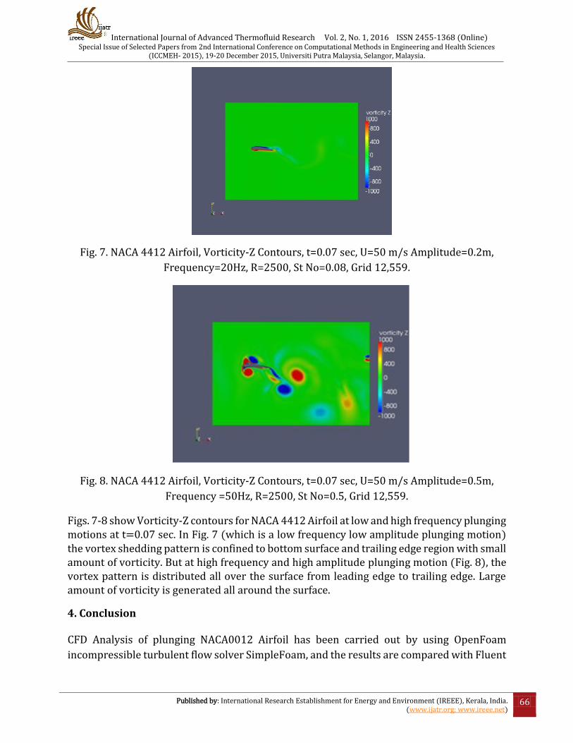
Fig. 7. NACA 4412 Airfoil, Vorticity-Z Contours, t=0.07 sec, U=50 m/s Amplitude=0.2m,
Frequency=20Hz, R=2500, St No=0.08, Grid 12,559.
Fig. 8. NACA 4412 Airfoil, Vorticity-Z Contours, t=0.07 sec, U=50 m/s Amplitude=0.5m,
Frequency =50Hz, R=2500, St No=0.5, Grid 12,559.
Figs. 7-8 show Vorticity-Z contours for NACA 4412 Airfoil at low and high frequency plunging motions at t=0.07 sec. In Fig. 7 (which is a low frequency low amplitude plunging motion) the vortex shedding pattern is confined to bottom surface and trailing edge region with small amount of vorticity. But at high frequency and high amplitude plunging motion (Fig. 8), the vortex pattern is distributed all over the surface from leading edge to trailing edge. Large amount of vorticity is generated all around the surface.
4. Conclusion CFD Analysis of plunging NACA0012 Airfoil has been carried out by using OpenFoam
incompressible turbulent flow solver SimpleFoam, and the results are compared with Fluent
International Journal of Advanced Thermofluid Research Vol. 2, No. 1, 2016 ISSN 2455-1368 (Online) Special Issue of Selected Papers from 2nd International Conference on Computational Methods in Engineering and Health Sciences
(ICCMEH- 2015), 19-20 December 2015, Universiti Putra Malaysia, Selangor, Malaysia.
Published by: International Research Establishment for Energy and Environment (IREEE), Kerala, India. (www.ijatr.org; www.ireee.net)
67
and Experimental data. OpenFoam solutions match the experiment and show good
agreement with Fluent. NACA 4412 Airfoil unsteady results indicate that Cl, Cd behavior is
uni-modal at low frequency plunging motion while it is multi-modal at high frequency
plunging motion.
ACKNOWLEDGMENTS
The authors would like to express gratitude for the funding received by the AR&DB project for carrying out the work and are grateful to the project team for their support and cooperation. References
Ashraf, MA, Lai, JCS and Young, J. (2007). Numerical Analysis of Flapping Wing
Aerodynamics, 16th Australasian Fluid Mechanics Conference, Crown Plaza, Gold Coast,
Australia, 2-7 December.
Heathcote, S and Gursul, I. (2006). Effect of Spanwise Flexibility on Flapping Wing
Propulsion, 35th AIAA Fluid Dynamics Conference and Exhibit.
Murthy SP, Muralidharan MR, Rao SU, Prasanti T. (2013). Parallel Performance of GPU and
CPU in Computational Fluid Dynamics, The 14th Asian Congress of Fluid Mechanics –
14ACFM, October 15-19, 2013, Hanoi and Halong, Vietnam.
Theodorsen, T. (1935). General Theory of Aerodynamic Instability and the Mechanism of
Flutter, NASA Report No. 496.