an implementation of ocr system based on - university of kent
TRANSCRIPT

Kent Academic RepositoryFull text document (pdf)
Copyright & reuse
Content in the Kent Academic Repository is made available for research purposes. Unless otherwise stated all
content is protected by copyright and in the absence of an open licence (eg Creative Commons), permissions
for further reuse of content should be sought from the publisher, author or other copyright holder.
Versions of research
The version in the Kent Academic Repository may differ from the final published version.
Users are advised to check http://kar.kent.ac.uk for the status of the paper. Users should always cite the
published version of record.
Enquiries
For any further enquiries regarding the licence status of this document, please contact:
If you believe this document infringes copyright then please contact the KAR admin team with the take-down
information provided at http://kar.kent.ac.uk/contact.html
Citation for published version
Li, Ning (1993) An Implementation of OCR System Based on Skeleton Matching. Technicalreport. University of Kent, Computing Laboratory, University of Kent, Canterbury, UK
DOI
Link to record in KAR
https://kar.kent.ac.uk/21129/
Document Version
UNSPECIFIED

An Implementation of OCR System
Based on Skeleton Matching
Ning LI
Computing Laboratory
University of Kent at Canterbury
United Kingdom
August 1991

Abstract
This report gives a general review of the development of Optical Character Recognition (OCR),
about its key problems and various of the techniques used. An implementation based on skeleton
matching is introduced in detail, which is used mainly for printed character recognition and is
insensitive to font style and size. This report emphasises on the implementation principles for
text sectioning, preclassifier design, thinning algorithm, template database and matching strategy.
An experiment is described to observe the system performance. Compared with conventional
methods used, this implementation has included some new techniques, such as character dimension
dependent broad classification method, AVP value used in fine classification and spelling check
based post-processing method, in order to obtain a good performance.
Chapter 1
Introduction
Optical Character Recognition (OCR) is the process by which the printed characters in a document
are converted automatically into computer internal codes that can be processed by computers as a
textual data file.
1.1 The use of OCR systems
At the present time, keyboarding remains the the most common way of inputting data into computers.
This is probably the most time consuming and labour intensive operation [Moore 1990]. OCR is
the machine replication of human reading and has been the subject of intensive research for more
than three decades [Stevens 1970, Rabinnow 1969, Andersson 1969]. The origin of the character
recognition can be found as early as 1870 when Carey invented the retina scanner, that is an
image transmission system using a mosaic of photocells. It first appeared as an aid to the visually
handicapped and the first successful attempt was made by the Russian scientist Tyurin in 1900. The
modern version of OCR appeared in 1940s with the development of the digital computers. It is
the first time OCR was realised as a data processing approach, with a particular application to the
business world [Mantas 1986]. The principle motivation for the development of OCR systems is
the increased demand for capturing printed documents or text as well as pictures. The application
areas include:
� Use by blind and deaf people
1
� Use of the photosensor as a reading aid and transfer of the recognition result into sound output
or tactile symbols through stimulators.
� Use in postal department
� Reading the address and post code to classify the different district mail.
� Use in machine vision
� Use in publishing industry and in library systems
� Combined with computer word processing and desk-top publishing techniques which have
been highly developed in recent years, OCR provides a revolutionary approach for computer
storing, editing, accessing, indexing and republishing documents.
� Use in direct processing of documents
� As a multi-purpose document reader for large scale data processing. A attempt made by an
UKC student to reproduce historical documents for teaching and researching history by the
the approach of OCR together with hypertext can be found in [McGuinness 1990].
� Use in bank and security service
� For reading bank cheques, credit card imprints, and personal signatures on identification
cards, etc.
� Use in business applications
� For reading product identification codes, goods declare forms and digital bar codes, etc.
1.2 The development of OCR systems
As long as the technical developments include the tremendous increase in computing power such
as the capacity and the speed, and falling costs, as well as the progress in scanning technology
stimulated by working out standards of Group Three digital facsimile, it is likely to result in a large
market in the near future for improved OCR systems [Moore 1990].
In the past decades, a large number of research works have been reported on this topic and many
commercial establishments have manufactured systems of varying capabilities. Portable, desk-top,
2

medium size and large size systems costing as high as half a million dollars are available, and are
in use for various applications [Govindan 1990].
Almost all the OCR systems have a number of difficult problems where recent advances in
these aspects have been made. Recognition rate is obviously of prime importance. This is an area
where systems have often fallen down. Recognition rate levels of 95% may sound high, but it still
means that there can be five mistakes in every hundred characters which is unacceptable for full
text retrieval applications. (One page of normal printed document may contain 5000 characters and
therefore 250 wrong characters may occur) The latest systems are claiming recognition rate levels
of over 99%. However the recognition rate is highly affected by many factors, such as the fonts,
type size, the quality of printing, the thickness of paper, the background of text, the resolution of
scanner and even the slight skewing of the text image to be scanned. The recognition rate may vary
from 100% to 50% or even lower. So, perhaps it is meaningless to measure the performance of
OCR systems only by the recognition rate.
The capability of processing characters in various fonts, typefaces, sizes and sets is also very
important. The very first systems could only process one or two sets of characters in fixed type
and size. This was the intention for issuing the OCR-A and OCR-B as two international standards
in 1968. However, they never became widely used as most application required using characters
which were not defined in these standards. Today the methodologies in character recognition
which use sophisticated techniques have enabled the recognition of a wide variety of both complex
typewritten and handwritten characters, symbols and word/script including Chinese and Japanese
characters. Because that the Chinese characters are ideographs composed by strokes which in
average are five times as many as in western characters, and the amount of daily used characters
is over 6000 which is roughly equivalent to entire western words, the computer recognition of
Chinese characters is considered to be a very hard problem and regarded as one of the ultimate goals
of character recognition research. Nowadays, many OCR systems developed in China and Japan
have reached fairly good performance. The information about this research can be found in [Zhang
1987, Yin+ 1986, CIRC 1988, Shu 1982, Mori+ 1980]. Besides these, so far we have seen systems
that can recognise English(Latin), Cyrillic(Russian), Arabic, Indian, Greek characters and so on, in
omnifont1.
Since western character recognition has its special difficulties compared with Chinese character
recognition, for example, the variable width and height, the overlapping and upper-lower cases,
1Characters with various fonts and sizes.
3

western character recognition is by no means easier. Other problems in handwritten character
recognition and script recognition as well as on-line recognition probably are more difficult, and
few systems are available in use today. For a review of this area please see [Davis+ 1986, Tappert+
1990, Nouboud+ 1990].
Speed of operation is also a factor. This is decided by the type of recognition logic employed
and usually is contrary to the recognition capability. The more characters can be recognised the
slower the speed is. As computer processing power has grown, so also has speed of processing
led by certain modern technologies such as concurrent processing and database technique, the time
taken in character recognition is now much less than in the past. Scanning time and the time used
in verification processing have to be taken account for as well. Modern systems can be expected to
take up to 60 seconds to scan and convert a page of text.
Finally, the question is price. Like most computer related technologies, this has been falling
steadily since the first working OCR systems were introduced. OCR can now be handled by a micro
computer, (an example can be referred to [CIRC 1988]) scanners are available for about the same
cost as a personal computer, and software to run the system can be purchased for hundreds rather
than thousands of pounds. Running costs including staff time, will have to be included on top.
Of course, larger scale systems offering a wider range of functions consequently cost higher price.
Some practical OCRs can be found in [Govindan 1990, Mantas 1986, Moore 1990] and their prices
vary from $1000 to half a million dollars.
Until recently however for most application efficient optical character recognition remained a
potential rather than a practical technology: recognition rate left much to be desired and the price
of OCR systems restricted its use to big organisations with continuing large scale text conversion
problems. Furthermore, the range of written material suited to OCR treatment was very limited
[Moore 1990].
1.3 Construction of OCR systems
In generally, a typical OCR system is composed by several parts as shown in Figure 1.1.
The system can be divided into four major parts, according to the dashed boxes in Figure 1.1.
They are:
1. Preprocessing part
The function of this part is using a page scanner to transfer the original text image into a
4

template database building
broad
scannerpageimagetext
...
page textbitmap
text analysis andcharacter section
finalclassification
featureextraction classification
featureextraction
preprocessing
recognition
self-learning
draftascii modification final
ascii text
postprocessing
Figure 1.1: Construction of an OCR system
bitmap file or binary matrix. Text analysis techniques are applied thereafter to section the
text image into lines and characters. The position of each character is recorded in order to
rebuild the ASCII text file.
2. Self-learning part
Most modern OCR systems have this function to enrich the knowledge when an unknown
character is met. Character recognition is based on the database previously built in, which
contains the important features related to the characters which are known already. It is
necessary that this database is able to self expand as more and more new characters are met in
order to increase the recognition ability. It is realised through adding new characters features
and their human-given meanings into the database.
3. Recognition part
This is the main part above all. It extracts input character features and compares these features
with those recorded in the database used by the recognition. If the features are matched or
closely matched, the input character is classified into a class within which all the characters
5

have these common features. The classification usually falls into several stages. The last
stage is called final classification while the others are called broad classification. After the
final classification, an individual character (result) is sorted out.
4. Postprocessing part
The ASCII text consisting of both the recognised and rejected characters normally needs
editing and modification. The purpose of this stage is to correct the mistakes, as they usually
appear after the recognition stage, and supply their due meanings (ASCII characters) to the
rejected characters.
For the preprocessing stage, the most important task is on the text section. A great many
documents comprise not only text lines, but also pictures, maps, forms, titles or headers, etc., while
the recognition stage can only process individual characters. Therefore, the superfluous information
other than character text should be removed.
The methodologies applied in the recognition stage are not different to that applied in any
general image pattern recognition problem, with respect to image analysis and pattern recognition.
However, because of the particularity of the character recognition problem, the main methodologies
used in OCR have formed their own family and can be summarised as follows [Gaillat and Berthod
1979].
1.4 Global analysis method
The key to the recognition is feature abstraction whose intention is to eliminate the redundant
information which is irrelevant to the attributes of the character, while its steadable information
which distinguishes this character from others should be extracted out for comparison use. Much
research has concentrated effort on this topic and they can be classified into two major categories
labeled as global analysis and structure analysis respectively. Global analysis directly makes use of
the shape matrix to find the features of characters. Some of the most important methods are listed
below.
1. Point by point global comparison
This is the traditional method implementedby pattern matching (also called matrix or template
matching) in which each digitised character is compared to a set of characters stored in
6

memory. When a character is matched (or closely matched), it is assigned the ASCII code
linked with the corresponding character template, see Figure 1.2.
11 1 11
1 11
11111
11
111111
1 1 11
111
11 1
1 1
1 1 111
111
1 1 11
111
11
1
1 1 11
11111
11 1
00 0 0
0000
0 0 00
XX
X111 X
X 1 XX X X X
1XX X 1
1XXX
1X
111111
1 1 11
111
11 1
1 1
X1111X
1
X
1
1
X
1
1
X
1
1
X1
Template characters in template database
A B
Input sample character
C
17 mismatched points 0 mismatched points 6 mismatched points
Digitized character Digitized sample compared with stored templates
Figure 1.2: Template matching of digitised characters
The process is repeated for each character in turn. The comparison methods can be as simple
as one-to-one comparison, or as complex as decision tree analysis in which only selected
pixels are tested. This type of technique suffers from sensitivity to noise and is not adaptive
to differences in writing style. As it is matching against existing pattern, the systems of this
kind only suit those fonts whose templates have already been stored, usually only one font or
typeface. However, this is a basic and effective approach.
2. Transformations
Global transformation and series expansion technique help to reduce dimensionality of the
feature vector and provides features invariant to some global deformations like translation
and rotation, since the properties of characters are described in different feature space, for
instance, frequency field. The possible transformations include Fourier, Hadamard, Rapid,
Karhunen-Loeve, Walsh, moment calculations, and finally rotations according to the principal
axis of inertia. An example of moment feature extraction is given below:
7

For a point in the matrixI�i� j�, the summary of distances from every point in the matrix is:
M�x� y� �mXi�1
nXj�1
G�i� j�ixjy
wherem� n is the matrix size,
G�i� j� �
�1 if �i� j� is a plack pixel
0 if �i� j� is a white pixel
x� y is called the order of the moment.
A class of moment features can be selected as
fM�0� 0��M�0� 1��M�1�0��M�1� 1�� � � � �M�u� v�g
�u� v� is a pair of arbitrary integer.
Such feature extraction techniques demand high computational requirements. The topological
feature is not used sufficiently.
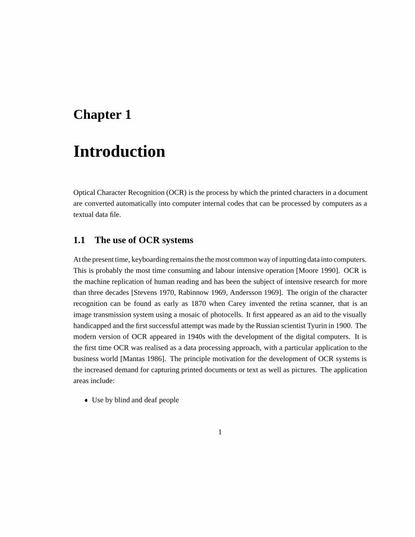
3. Cellular features
This method divides a character inton� n components (Cellulars). Each cellular is checked
in turn in eight directions to see if it has a horizontal or vertical stroke passing through. If
it has, the cellular with its position is marked as a cellular feature. The input character can
be sorted out by comparing these features with those stored in the template database. See
Figure 1.3. It is useful in recognition of printed characters.
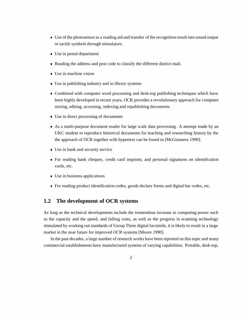
4. X- Y- projection
Projecting the character shape in X and Y directions, two projection values can be obtained,
each of which represents the stroke distributions on these two directions. These values are
good feature properties after Fourier transformation and can be used in broad classification
(refer to the recognition stage described above). This method is shown in Figure 1.4.
5. Mesh features
Firstly the character matrix is divided intom�n components. Then for each component, the
proportion between the areas of strokes and of the whole element is calculated. Them � n
proportions form a mesh feature space, see Figure 1.5. It is often used in printed character
recognition.
8
10 0
0 0
0 0
0
0 0
00 0
0 0
0 01
1 11
1
11
Figure 1.3: Cellular features
10
8
6
4
2
0
Y-projection
X-projection
K 8 2 06 4
Figure 1.4: X- Y- projection features
9

K Mesh Features of ’K’
Figure 1.5: Mesh features
Besides these, there are many features obtained from other global analysis manners, such as
peripheral features, surrounding coding features, Loci features, etc. Useful reading matter can be
found in [Lin+ 1987, Sakai+ 1976, Glucksman 1971].
1.5 Structure analysis method
Geometrical and topological feature analysis methods are the most popular technique investigated by
researchers. The features may represent global and local properties of the characters. These include
strokes, bays in various directions, end points, intersections of line segments, loops, stroke relations,
angular properties and sharp protrusions. These features have high tolerance to distortions and style
variations, and also tolerate a certain degree of translation and rotation. They help to process
characters at high speeds. However, the extraction processes are normally very complex, and it
is difficult to generate masks for these type of features. Furthermore, these methods work well
in recognition of characters which are mainly composed by vertical and horizontal strokes, like
Chinese. While for western characters, they are probably less suitable. Some important methods
are illustrated below.
1. Outline features
The outline shape of a character usually contains very distinct and stable information to
distinguish it from others. The contour can be achieved by contour tracing as proposed
in [Bakis+ 1968]. The outline features like end points, intersections of line segments, bays,
loops, length, directions, bumps and holes can easily be derived from the contour information.
10

2. Skeleton features of strokes
The skeleton of a character embodys the basic shape information which is, in a sense, font
independent. Extracting high quality skeleton for skeleton matching and topological analysis
is therefore an ideal method for characters recognition, whereas in practice it remains a dream
of many technicians, because of its subjective character and hard to avoid deformations.
Plenty of reports about this research in past years can be found. For some examples, see
[O’Gorman 1990, Y.S.Chen+ 1990, Sossa 1990, C.S.Chen+ 1990, Bourbakis 1989, Xia 1989,
Arcelli 1985 1981]. Most of the skeletonisationalgorithms can be classified into two essential
types. The first one is medial-axis transform (MAT), which searches for the set of centers and
radii of the maximal blocks contained in the objects. This kind of algorithm can preserve all
the details of the objects. However, it cannot make sure that all the initial object’s topology can
be preserved due to the property of discrete space. Moreover, it manifests noise-sensitivity.
The second type is referred to as thinning algorithms. The essence of this approach is to delete
iteratively the border points if their removal does not effect the connectivity of the objects.
This kind of algorithm usually has to use template matching and contour tracing because of
the the disconnection of the original pattern into a number of components. The time required
in these algorithms is linearly proportional to the pattern area, i.e, the size of images and the
maximal thickness of the pattern. For this reason, parallel approaches appeared to make the
process faster. In parallel thinning, all the pixels of the pattern are examined and, if necessary,
removed simultaneously. Skeleton features can be used together with topological analysis to
get end points, intersections of line segments, bays, loops, directions, bumps and holes, that
might be used in the final classification.
3. Complex index features
Complex index is the value which represents the degree of complexity in both vertical and
horizontal directions. It can be described as a ratio between the total stroke length in one
direction and the stroke’s density in that direction. It is usually used in broad classification.
4. Edges and line segments
Using a sub window movingacross the shape matrix, a series of segments of lines is generated,
by which the slope and curvature of the line can be evaluated. These features can be used to
establish the graph representation of the characters. Having this representation, end points,
intersection points, nodes or loops of the stroke can easily be found. They may be used in
11

recognition of hand written characters.
Besides these, some other solutions such as root resolving, stroke transform and coding etc., are
also used. Reading matter can be found in [Stallings 1972, Jeng and Chang 1988] .
Self-learning is a fundamental procedure in the intelligent OCR systems. In some systems
such as Kurtzweil K-5100 which is used in University of London Computer Center, when unknown
characters are encountered, they are shown on the screen and the operator can key in their meanings.
After that, the computer can “remember” these characters and it never interrogates the operator when
meets them again. It can be thought of as “learning from experience”. Since it goes along as it
learns, more and more characters can be recognised. However, the methodology used here is rather
of database techniques than OCR itself. It demands that the feature abstraction should be processed
automatically and template databases have to be expandable.
Another important aspect in recognition is the clustering and comparing algorithm. For the
character sets of large quantities, it is useful to use clustering method to put the characters which have
similar features into a cluster, according to a certain criteria. Through this classification, the number
of characters to be compared with is reduced significantly, so some sort of real time processing can
be achieved. The recognition rate can be increased as well, since the final classification algorithm
can be applied within a smaller cluster and performed thoroughly. Assume that the whole feature
space isSw,C1� C2� � � � � Cn are clusters inSw, i.e.,C1� C2� � � � � Cn � Sw, LetV be feature variance
in the feature space.V �Sw� is the total variance in the whole space, whileV �Ci� Cj� �i� j � n� and
V �Ck� represent the between cluster and within cluster invariance respectively. We have
V �Sw� � Vb � Vw
V �b� �nXi�1
nXj�1
V �Ci� Cj�
V �w� �nX
k�1
V �Ck�
The purpose of classification is to maximiseV �b� and minimiseV �w� based on the similarity
of certain character features. The similarity can be measured by Euclidean Distance, Minkowsky
Distance, Correlation Coefficient, etc., while the classification methods can be chosen from Batche-
lor and Wilkin’s, H-means, K-means, Neighbourhood Function and Hidden Markov Model(HMM),
etc. For detailed discussion please see [Jeng+ 90].
12

After feature abstraction, the features must be compared with those stored in the template
database. The entry of the best matched character in the database is the recognition result. An
example of an employed method is the Template Matching method.
We assume that the input character feature is�X1� X2� � � � � Xn�and template feature is�Yi1� Yi2� � � � � Yin�,
i � 1� � � � � k, i.e., it hask clusters. Sample distance is represented as:
S�Xi� Yik� ��Xi� Yik�
kXik kYikk
wherekXik� kYikk are the vector distances,�Xi� Yik� is inner product of vectors, its value is between
0 and 1 after normalisation.
The more similar the two vectors are, the larger the value ofS. WhenS gets its maximum
value, the corresponding template character is the recognition result.
Some other methodsused include Relaxation Matching, Differential Pattern Matching, Dynamic
Programming, Vector Quantisation, Neural Networks and Branch and Bound Search. For more
informations please see [Jeng 1990].
Not only a good recognition strategy can achieve a high recognition rate, but also additional
methods can significantly improve its performance. Postprocessing is another important stage
in the whole procedure, whose aim is to reduce the mistakes in the result. Up to now, none
of the recognition algorithms can avoid making errors, i.e., have 100% recognition rate in all
circumstances. For this reason, means for finding and correcting such errors are indispensable.
Several approaches have been developed to detect misspelled words and offer suggestions for the
correct word. (see [Peterson 1980]) With the progress in database systems, various question-and-
answer systems have also appeared. Usually these systems search for a word that corresponds
exactly to the input in a built in dictionary. If they fail in searching for the input word, however,
they merely display a warning message. For more flexible human-machine communication, it is
desirable to use a spelling correction programme to search for the most likely word. Research work
in this area can be found in [Takahashi+ 1989, Sinha 1989, Wells 1989]). Beside this semantic
analysis, context based syntactic analysis is desirable. However it is still a unsolved problem in
artificial intelligent and natural language understanding, and the technique rarely appears in the
commercial systems.
This report describes a current system that recognises printed characters of certain fonts and
various sizes for the Roman alphabets. The system combines several techniques in order to improve
the overall recognition rate. The result has achieved a fairly good recognition rate and processing
13

time is comparatively short. Anyhow, the research so far is not complete. Some additional
techniques such as separating merged and joined characters could be applied to get better result.
Nevertheless, some characteristics of this system can be summarised as below:
1. A friendly user interface was developed using X11 programming environment. Users can
easily chose functions such as building up template databases, clipping a text image, setting
preknowledge, previewing text file and monitoring the performance, etc.
2. Scaling is used directly on the text image at first. All the characters fall into four classes
corresponding to the four template databases. This can significantly reduce the effects of
noise and distortion from the thinning algorithm. From a user’s point of view, it can deal with
various sizes of characters.
3. An efficient thinning algorithm is applied to abstract the skeleton of the character image.
Because the skeleton contains most of the structural information which are font independent
or nearly independent, using skeleton matching combined with the scaling technique can suit
the need of “omnifont” recognition.
4. An approximative comparing algorithm is used. Clustering and classification is based on
the dimensions of characters. The comparison method incorporates the features of Dynamic
Programming [Fu+ 1986] and Neural Networks [Rokert 1988], to get a closest matching
result. Therefore, this system allows certain distortion to exist between sample and template
characters so as to suit the wide applications.
As we described above, the global statistic analysis is more suited for processing a large quantity
of characters as it is less time consuming, and for buildingup template database for the reason of easy
feature abstraction; while the structure analysis is more ideal for processing various fonts and sizes
because of owning better feature space. For printed character recognition, as well as the main aim
of this system, it is desirable to combine the advantages of each of them. In this implementation,
the skeleton analysis is a structural method whereas the matching is by a point-to-point global
comparison. The benefit is that a good feature space can be established, however the processing
is rather simple. Furthermore, the skeleton-based template database is not as large as that used
in normal point-to-point matching, since it needs less templates in the database. A compression
technique is also applied to make the database as small as possible.
14

Chapter 2
System outline
Xocr (X-environment Optical Character Recognition) is a real implementation of the character
recognition system. So far, it contains nearly 10,000 C source lines and was developed in about one
years time. At the first beginning, we have following design goals in mind:
1. Combine as much as possible of efficient feature analysis with global analysis techniques to
achieve good overall recognition rate.
2. Aim at printed character recognition and to achieve the flexibility for the case of omnifont
processing as much as possible.
3. Avoid making any change in system software and hardware, make full use of the existing
facilities with ordinary system configuration.
4. Realise the system as succinctly as possible and make it easy to put into practical use.
2.1 System support
This system is developed on Sun workstations with SunOS1 and X112 Window System. The system
is written in C language and X interface. A page scanner was used to generate the bitmap images
which normally have 300dpi resolution. The computer used was Sun4 workstation linked by NFS
1Sun, SunOS and Sun workstations are trademarks of Sun Microsystems, Inc.2X Window is trademark of the Massachusetts Institute of Technology.
15

network with at least 8 Mbyte direct memory space and virtual memory. The real image was
captured by a HP ScanJet Plus3 image scanner which had 300 dpi resolution. It allows the pictures
up to A4 size to be digitally sampled and turned into bitmap files that can be edited or stored on
disk. Thexscan interface has been used which allows images to be easily scanned and saved in
various formats and size [Hesketh 1990].
“When run,xscandisplays a window containing two main areas: the preview area
and control area, see Figure 2.1.
Figure 2.1:Xscan user interface
The preview area contains a preview scan of the available scanning area which
allows the user to choose which part of the A4 area to scan in detail. To produce
a preview scan you should place down on the scanner’s surface the photographs or
images to be scanned and then click on the Preview Scan button just above the preview
scan area. The scanner takes a few moments to traverse the whole of the scannable
area and then preview image is displayed.
3HP ScanJet Plus is trademark of Hewlett Packard Company.
16

When the preview scan completed you can now choose to perform an Image Scan
on a particular part of the scannerable area. To choose this area drag out a rubber
box using the left mouse button. This defines the area that the scanner will scan in
detail. The control area has various controls that allow you to change the dots-per-inch
scanning resolution or to set the type of output.
The scanned image is saved to a file whose name is given in the box in the top right
hand corner. This should be a unix file name and relative to the directory thatxscan
was start from.
Xscan uses the Sun rasterfile format to save the image it scans. the image can be
saved as one of two distinct types:
� Bitmap image – A bitmap image is one which has two colours, a foreground and
background colour. (This is the only image type that can be used in thexocr
system)
� Greyscale image – A greyscale image is made up of different shades of gray
ranging from black to white. These images can only be viewed directly on a
colour screen and produce results similar to black and white photographs.
� � � Greyscale images can be rendered as bitmaps using two normal methods,
they can be either dithered using any one of the four dither patterns built in to the
scanner or they can be thresholded.� � � Thresholding by hand can use thegip
command.” (More information aboutgip can be found in [Hesketh 1990]).
The user uses the four parameter boxes on the right of thexscan screen to obtain the optimum
settings. The resolution and intensity control are heavily used in prepare scanning documents for
xocr . Various values might be tried by various values before an optimised setting has been found.
The quality of scanned image can be examined through file viewer tools likevf [Russell+ 1985].
For bitmap images, contrast has no effect on the result. Automatic background control which
can filter background noise but might bring some losses on the pattern edges and make some strokes
broken, thus we should take care in using it.
In fact,xocr can accept two kinds of image input format, one is X11 bitmap file, the other Sun
raster file. However, only X11 bitmap file is used internally. Sun raster file will be transformed into
X11 bitmap file automaticly using thesuntox11facility provided by the X11 system. The definitions
17

of the header structure of rasterfile and bitmap can be found in the manual page RASTERFILE(5)
and BITMAP(1).
2.2 Xocr user interface
Xocr command usage is:
xocr [-bm bitmap-file] [-rf raster-file]
[-tdir tdb-dir]
[-tdb1 first-tdb-name] [-tdb2 second-tdb-name]
[-tdb3 third-tdb-name] [-tdb4 fourth-tdb-name]
[-out ascii-output-file]
[X options� � � ]
where,-bm and-rf options indicate whether a bitmap or Sun raster file is used as input text image.
-tdir followed by tdb-dir indicates which directory the template databases are accommodated in.
Different set of template databases scatted in different directory can be chosen by this option.first-
tdb-name, second-tdb-name, third-tdb-nameandfourth-tdb-nameare the names of four template
database files used byxocr (described later).Ascii-output-fileis the file name where the recognition
result – ascii coded characters are written. By default, thetdb-dir is the current working directory;
the template databases used aretdb1.Z, tdb2.Z, tdb3.Zandtdb4.Z, whereas they might not exist
at the beginning. (.Z is the suffix of compressed file names, see COMPRESS(1)). The default
ascii-output-fileis ascii.out.
After a proper command has been keyed in, an typicalxocr user interface is shown as Figure 2.2.
Xocr provides a window consisting of the following five areas:
1. Operation section
This area contains all the buttons to activate operations, such as to clip a region, i.e., choose
a part of whole image for processing; set preknowledge (described later), build up template
database, start recognition, preview ascii output file, monitor the performance, change related
file name and inquire system parameters and so on.
2. Message window
This area displays the system messages to feed back to the user.
18

Figure 2.2:Xocr user interface
19

3. Input window
This area is headed by an input flag which is set when an input is needed. The input
information is edited and accepted within this area.
4. Text image display window
When a text image file whether in raster file or bitmap file format has been properly indicated,
the text image is loaded here after a short delay. When the clipping region operation is
selected in the operation selection area, a rubber-band-rectangle can be dragged out from this
window to choose the working area. The window can scroll in both vertical and horizontal
directions. The mouse pointer position in this window can be reflected from the position
display window above when any mouse button has been pressed.
The ascii text (recognition result) is also displayed and edited here when text preview is
selected.
Relevant operations
1. Clip a region
Firstly, select the ‘Region clip’ button. Then move the mouse to the image window, press
the left button, a rubber- band-rectangle will appear. The dragging can be continued after
the image scrolling (in case of dealing with the image part outside the display window) by
pressing the middle button while moving the mouse. After the rectangle has covered the
proper area, pressing the right button will save the clipping. Once the left button has been
pressed, the previous region will be lost.
2. Pre-knowledge set
There are two pre-knowledge, which are the size of character ‘O’ and the offset between
two words. They can significantly benefit the section procedure. The input image will
be sectioned into lines and characters, these two pre-knowledge can help to make good
justification between upper case and lower case characters, and also help to separate the
words correctly. Therefore, the user would be better give these two values. The former can
be obtained by clipping a capital letter ‘O’ in the image wherever possible, if not, other capital
letters can be instead. The latter is input through the input window.
3. Template setup
The template can be setup whether at the beginning or in the middle ofxocr execution
20

(except that it has to be done at the beginning when none of the templates is available). When
‘Template setup’ has been selected, a section process starts, then a box will be around each
character, and it waits for the user to input the name of the character. After the input has
been given, a check procedure will be exerted to avoid building redundant template in the
database. The input of the character name should be paid a great attention, since the input
will directly write to the database file and there is no easy way to correct the mistakes. The
template comes from a region if a region has been selected or from the whole image if no
region has been found.
4. Recognition
There are two options to the recognition. When ‘Interactive’ has been selected,xocr will
stop at each unknown character which has not been met before, in other words, no template
in the database can match the input character. After the user has input the character name,
the recognition will continue, and the unknown character is remembered. This is called
self-learning. For non-interactive recognition,xocr never stops at any character, and marks
any unknown characters as ‘[]’ which means that the characters are rejected. The number of
recognised characters is displayed on the output window while the recognition is working.
5. Inquire values
Some important parameters used byxocr can be inquired and will be displayed on the output
window when the user selects the name concerned in ‘Value inquire’.
6. Performance display
When the user selects the ‘Performance’ button, the statistic result of the last recognition
will be displayed on the output window, which includes: the total characters, rejected ones,
recognition rate, time used and so on.
7. Ascii text preview
The recognition result is ascii text, and can be displayed and edited at this stage. There are
two options to view the text, one is with spelling check and another is without spelling check.
Because some similar characters like ‘1’ and ‘l’ may be confused when being recognised,
sometimes we need a spelling check to pick out these mistakes.
When the user previews the text with spelling check, the ascii text is displayed on the text
display window (or the image window), two subwindows will popuped as well and can be
21

placed anywhere convenient. One of the subwindows is named ‘Misspelled’ which contains
all the mis-spelled words, another is ‘Suggestion’ which contains possible correct options
for each mis-spelled word. When the user types <ctr-R>, the third subwindow which is the
replace window will be popup. This is part of the operations of Athena asciiText widget,
further information about this can be found in the relevant document. To get the suggestions,
the user can move the mouse to one of the mis-spelled words in ‘Misspelled’ window and
press the left button twice. Soon afterwards, the corresponding suggestion will appear in the
‘Suggestion’ window. The current mis-spelled word will automatically become the search
text of the replace window. When the user chooses the preferred suggestion by pressing
the left button twice in ‘Suggestion’ window, the right word will become the replace text of
replace window. Then the user can press the ‘Search’ and ‘Replace’ button to replace the
text. All the text windows are fully editable.
When the user chooses the preview function without spelling check, only the ascii text is
displayed on the text display window.
Selecting any button will save the text file.
8. Rotate the image
A scanned image usually appears inclined, it can be corrected by this command. When the
user has chosen this button, there will be five new windows and two new button placed in the
input area, which are listed below:
(1) X0 and Y0: Coordinates of the first pixel in a inclined line;
(2) X1 and Y1: Coordinates of the second pixel in the same inclined line;
(3) Ok: This is the button to start image rotation;
(4) Cancel: This button will end the image rotation, and restore the input area as before.
(X0, Y0) and (X1, Y1) could be any pixels in the same inclined line.Xocr determines the
rotating angle by these two coordinates. After the image has been rotated, the inclined line
will become a horizontal one. This function sometimes might cause some loss of image
quality.
9. Others
File names can be changed and bitmap or raster image file can be reloaded through the popup
22

menus of this selection. It is the normal way to quit the text preview and go on to process
next document image.
For further details please refer to the manual page XOCR(1).
The next part will explain how the functions are realised according to each of the stage described
above.
23

Chapter 3
System Implementation
3.1 Preprocessing
3.1.1 Inclined image correction
A scanned image usually appears inclined. This is because that there is no mechanism available
in ordinary scanner to easily correct this inclination. However, the image inclination has a serious
effect on the section stage. The text image might not be sectioned into lines to lines correctly
because the detection of lines is based on the horizontal projection, and no evident zero projections
could be found in heavily inclined images.
Image rotation is realised by the trigonometric transformation to of each pixel in the bitmap.
The rotation is around the up-left corner of the original image. The user inputs coordinates of two
pixels in the same inclined line. The angle formed by the line passing through the two pixels and
the horizontal line is the rotation angle. Rotating the image by this angle in the opposite direction
results in the corrected image.
LetF �i� j� be the pixel in�x� y� position of the text image:
F �i� j� �
�0 for white pixels
1 for black pixels�3�1�
The image is like in Figure 3.1, where�Xs� Ys� is the up-left corner of the image while�Xe� Ye�
is the bottom-right corner.
Let �x0� y0� and�X1� Y1� be the two coordinates input by the user, the rotation angle� is:
24

1
i
Xe
F(i, j)
Xs
Ys
Ye
j
B
Figure 3.1: The image
� � �arc tany1� y0
x1� x0�3�2�
�x1� x0 � 0�
LetP �x� y� be a black pixel in the original image B. The new pixel position in the transformed
image B’ isP ��x�� y��:
P ��x�� y�� �
�x� � rcos��0 � ��
y� � rsin��0 � ���3�3�
where:
r � ��x1� x0�2 � �y1� y0�
2�1�2
�0 � arc tan�y�x� where x�� 0
See Figure 3.2.
3.1.2 Line section and character section
The text image scanned by a image scanner may contain text, titles, pictures, graphics, tables and so
on. Some noise may also be involved. Text section is processed manually instead of auto analysis.
This is because that on the one hand, to separate text image from titles, pictures or graphics is no
longer a difficult task for the operator using mouse dragging in a window system, and the amount
25

B’B
10
(x , y )(x , y )
P(x, y)
P’(x’, y’)
x
y
0 01 1
r
r
Figure 3.2: Image rotation
of separation work is usually not too much; on the other hand, choosing the text image by hand
can increase the system flexibility since not all the text image is always needed for recognition in
practice.
The section algorithms must be performed upon the pure text image in order to get the informa-
tion for each characters. The later stage can use this information to find each character in the whole
text image and reorganise the ascii text in the same sequence as the original characters appeared.
The information from text analysis is recorded in the following data structure namedinfo type.
typedef struct {
int up_position; /* Position of top edge of the current line */
int low_position; /* position of bottom edge of the current line */
char_info_type char_info[MAX_CHAR]; /* Information of each character
in current line */
info_type *next; /* Pointer to next line */
}info_type;
char info type is defined as:
typedef struct {
int up_position; /* Top edge of the current character */
26

int low_position; /* Bottom edge of the current character */
int left_position; /* Left edge of the current character */
int right_position; /* Right edge of the current character */
int ccase; /* The value is as below if it discovered that
current character is of:
0 -- Upper case
1 -- lower case
2 -- special character like ‘.’,‘’’,‘:’,... */
char name[CHARNAME_MAX]; /* The ascii name of this current character */
char_info_type * next; /* Pointer to next char */
}char_info_type;
The information is stored in a global array of structures with above type. The information is
grabbed by two steps:
Line section
Line section finds the top and bottom edges of each text line in the text image. The principle used
here is horizontal projection analysis.
Let F �i� j� be the same image shown above. The projection of all pixels in the horizontal
direction is:
Ph�j� �XeX
j�Xs
F �i� j� �3�4�
F �i� j� � B�Xs� Xe� Ys� Ye�
The top edge of the line can be judged by formula 3.5.i is the top edge of the line, if it satisfies:
�LXj�1
F �i� j� P1� �LXj�1
F �i� 1� j� P2� � � � �LXj�1
F �i� k� j� Pk�1� �3�5�
whereL is the length of current line,k� P1� � � � � Pk�1 are constants greater than 0. In the case
when noise exists, assume that maximum width and height of noise areNw andNh, a supplement
condition is:
27
�Nw � min�P1� P2� P3� � � � � Pk�1�� �k � Nh� �3�6�
Similar with top edge decision,i is the bottom edge of the line ifi satisfies:
�LXj�1
F �i� j� � Q1��LXj�1
F �i�1� j� � Q2�� � ��LXj�1
F �i�m� j�� Qm�1��LXj�1
F �i�m�1� j� � 0�
�3�7�
wherem�Q1� � � � � Qm�1 are constants not less than 0. In the case when noise exists, the supple-
mentary condition is:
Nw max�Q1� Q2� Q3� � � � � Qm�1� �3�8�
The decision ofNw� Nh can be set as a portion of the width and height of standard character –
Wpk andHpk in the preknowledge. (Normally they are the width and height of ‘O’), for instance,
Nw � a0Wpk
Nw � a1Hpk
In this systema0 anda1 are all equal to 1/20 which are experimental results.
If the preknowledge has not been given, they are set to the default values obtained from
experiment.
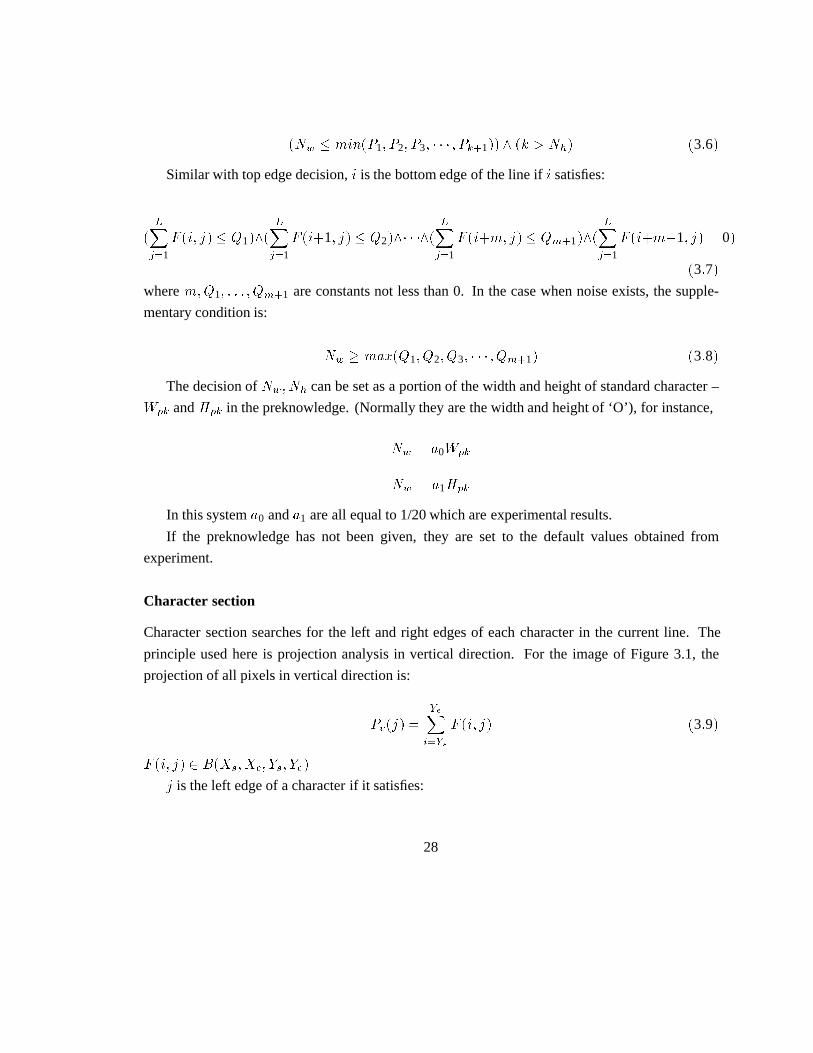
Character section
Character section searches for the left and right edges of each character in the current line. The
principle used here is projection analysis in vertical direction. For the image of Figure 3.1, the
projection of all pixels in vertical direction is:
Pv�j� �YeX
i�Ys
F �i� j� �3�9�
F �i� j� � B�Xs� Xe� Ys� Ye�
j is the left edge of a character if it satisfies:
28

�HXi�1
F �i� j� P1� �HXi�1
F �i� j � 1� P2� � � � �HXi�1
F �i� j � k� Pk�1� �3�10�
whereH is the height of current line,k� P1� � � � � Pk�1 are constants greater than 0. In the case when
noise exists, another condition have to be added:
�Nh � min�P1� P2� P3� � � � � Pk�1�� �k � Nw� �3�11�
Similar with top edge decision,j is the right edge of the line if it satisfies:
�HXi�1
F �i� j� � Q1��HXi�1
F �i� j�1� � Q2�� � ��HXi�1
F �i� j�m� � Qm�1��HXi�1
F �i� j�m�1� � 0�
�3�12�
wherem�Q1� � � � � Qm�1 are constants not less than 0. In the case when noise exists, another
condition have to be added:
Nh max�Q1� Q2� � � � � Qm�1� �3�13�
However, character section is much more complex than line section. This is because in many
sample documents, lots of characters are either overlapped (merged) or joined. See Figure 3.3.
Figure 3.3: (a) Overlapped (merged) characters ‘tu’ : (b) Joined characters ‘mn’
In the situation listed above, it is almost impossible to use the projection method to get fair
results. Let us see the vertical projection of ‘tu’ as in Figure 3.4, where there is no evident trough
which can be used as a criterion to separate these characters.
It might be argued that in case of Figure 3.3 (b) that threshold could be used in this case.
Unfortunately, it is not always true. Also see Figure 3.4. We notice that the projection of ‘u’
29

tu
Y-projection
Figure 3.4: Y-projection of overlapped ‘tu’
sometimes has a very similar trough inside the character so that it is hard to tell which trough can
be considered as threshold to separate characters or as the property of a character to be preserved,
i.e., if we want to separate ‘t’,‘u’, ‘u’ must be broken too.
For the situation of Figure 3.3 (a), an alternative approach in our early research was proposed
based on contour filling by connectivity (see [Pavlidis 1982]).
We firstly select a point which is the leftmost dark pixel in the current line as a seed and propagate
its colour (values other than 0, 1 which indicate white or white pixels) to adjacent pixels until the
contour of a character is reached. (For discrete characters, contour is of one of its components) The
algorithm can be described recursively in simple terms: LetC be the colour of the seed,S andF
be the filled region at some step. We setF � S initially, and then at each step we add toF all
pixels whose colour isC if who have a direct neighbour inF . Thus the contour filling is performed
on the basis of connectivity. After the contour of the first character has been found the algorithm
is repeated from the second seed in right direction whose colour is set different from the previous
one, until all the characters in the current line are achieved.
Recursive filling algorithm can be described below.
Definition 1 Two pixels are said to bedirect neighbours (abbreviated asd-neighbours) if the
respective cells share a side, and indirect neighbours (abbreviated as i-neighbours) if those cells
30

touch only at a corner. The name neighbour denotes either type. The term N-neighbour where
0� N � 7 will be used to denote that pixel whose position is markedN in Figure 3.5.
P 0
123
4
5 6 7
Figure 3.5: N-neighbours
Algorithm 1 RecursiveFilling
BEGIN
Set seed to mostleft pixel of current text line
WHILE seed not meet the mostright pixel of the current line
C = COLOUR(seed)
CALL FILL(seed)
seed = SECONDSEED(seed)
ENDWHILE
END
Procedure 1 Fill(P)
BEGIN
Set the colour of p to C
FOR n = 1, 2, 3, 4, 5, 6
IF the colour ofPN is not C
CALL FILL( PN )
f PN denotes the N-neighbour of P, 0� N � 7 g
ENDIF
ENDFOR
END
31

Function 1 COLOUR(P)
BEGIN
IF P is the first seed
RETURN 1
ELSE
RETURN last seed’s colour + 1
ENDIF
End
Function 2 SECOND SEED(P)
BEGIN
RETURN nearest pixel to the previous seed in right
direction whose value is not the colour of previous seed
END
However, this solution is difficult to use in practice. This is because the poor quality scanned
images contain many broken strokes thus a character has no connectivity expected. Moreover, it
brings some side affects. For instance, a discrete character will divide into several parts, these must
be recognised separately and we have to use a additional algorithm to combine them. Another
problem is that this algorithm is extraordinary time consuming.
For the time being, no special effort has been made for this case. The merged characters are left
alone. They will be rejected or recognised by the operator in the recognition stage. It is hoped that
a better solution can be found and applied to the system in the future.
As for the case of Figure 3.3(b), we consider the connected characters as a single character.
At first look, one may think that the possible combinations of connected characters would be of
huge amount. However, the only possible combinations in a real document should be existed in
a dictionary. Therefore, a solution can be made to pick out all the possible combinations from a
dictionary and store their templates in the database. The number of combinations might not be too
large. Also because this situation does not happen frequently, it is believed that the four template
databases idea (described later) can support this implementation since the combinations are usually
stored in the 32�24 database which is rarely used in normal sample comparison. Furthermore,
some unseparated characters can also be processed in the postprocessing stage.
32

3.1.3 Preclassification and normalising
In this system, all the characters are classified into four classes according to their dimensions. The
reason for doing so is:
� This method can process various sizes of characters.
� The global point-to-point comparison of skeletons needs the sample characters to have same
dimensions of the templates.
� This is one kind of broad classification which can speed up the recognition procedure and
improve the recognition rate.
� The most important point is that it can overcome the deforms caused by most thinning
algorithms to a great extent, as we know that thinning deforms increase with the thickness of
the patterns. Many characters or symbols have very simple strokes such as ‘I’, ‘l’, ‘.’ and
‘-’, in conventional processing, they will be scaled into only one dimension. A stop mark ‘.’
printed on a paper often becomes a blob after scanning and normalisation. See left side of
Figure 3.6 (a).
It can be said that there is no thinning algorithm can get correct result from these patterns.
The deforms also occur when thinning the characters or symbols like ‘I’, ‘l’ and ‘-’, etc.
However if the scaled size is not too big, say 4�4 instead of 16�16 in Figure 3.6 (b), the
thinning result may be very close to the correct result.
16X16 dot pattern
(a) (b)
16X16 thinning result
4X4 dot pattern 4X4 thinning result
Figure 3.6: Thinning result of a dot pattern
In order to get a better result, some characters like ‘.’,‘-’ and ‘|’ are firstly detected to assign
their meanings instead of being recognised later. The detection is according to the standard
33

character dimension given by the preknowledge or according to the average dimension.
� Another important use is that it can reduce or eliminate noise. The noise usually has very
small dimensions. If it is scaled down, which is the normal case in the system (described
later), a blob of noize in the printed paper may become only a single point in the scaled image.
It may not have serious effects on the recognition stage if we use the later described matching
algorithm.
The scaled dimension should neither be too big nor too small. If it is too large, the comparison
time will be increased and recognition speed will slow down. If it is too small, some details of
strokes may be lost after scaling. We chose the dimensions of 32�24, 24�24, 12�24 and 12�12
just because that they are suitable for this purpose. The normally used font size is about 12 point (1/6
inch) on ordinary printed documents. If it is scanned by 300 dpi, which is the ordinary resolution,
a character pattern contains 50�50 pixels will be generated. For an English character set, a most
complicated character may contain no more than 4 strokes in one side. Thus a reasonable dimension
should be able to distinguish 8-9 (4�2) lines in each side. See Figure 3.7.
In other words, the dimension chosen for an ordinary character should not be smaller than 9�9.
On the other hand, an original stroke with normal width 6 (50/9) pixels, will have 4 pixels width in
32�32 dimension it might be about 4 pixels; in 24�24 dimension about 2.8 pixels and in 12�12
about 1.4 pixels. They are enough to preserve most details of the strokes. The scaled pattern of
Figure 3.7 (a) in 32�32, 24�24 and 12�12 are shown in Figure 3.7 (b), (c) and (d) respectively.
Therefore, four default template databases are used, they are:
tdb 32�24 This database usually stores template skeletons of very wide characters. Most of
connected characters are stored here as well.
tdb 24�24 This database usually stores characters with normal dimensions, like ‘A’, ‘e’, ‘2’, ‘&’,
etc.
tdb 12�24 This database usually stores “thin’ characters like ‘1’, ‘l’, ‘i’, etc.
tdb 12�12 This database usually stores very small characters like ‘,’, ‘*’, ‘’’, etc.
The classification is processed automatically. A set of approximate criteria to classify a character
into one of the four classes is described below. Some characters with border dimensions exist in
more than one database in order to increase the “hit percentage”.
34

(c) "M" in 24X24
(b) "M" in 32X32
(a) "M" in 50X50
(d) "M" in 12X12
Figure 3.7: ‘M’ in different sizes
35

LetCw andCh be the width and height (in pixels) of characterC,Wj andHj be the yardsticks
used to judge which class C falls into.
C belongs totdb 32�24 if Cw andCh satisfy the following conditions:
�Cw � a0Wj�� ��Wj � Cw � a0Wj� � �Cw � a0Cw � 1��
C belongs totdb 24�24 if Cw andCh satisfy the following conditions:
�Wj � Cw � a0Wj� �
�Cw � a0Wj �Cw � a1Cw � 1���
�Cw � Wj � �Cw � a1Cw � 1��
C belongs totdb 12�24 if Cw andCh satisfy the following conditions:
���Cw � a1Cw � 1� � Wj� �Ch � Hj���
���Cw � a1Cw � 1� � Wj� ��Ch � a1Ch � 1� � Hj � Ch� ��Ch � a1Ch � 1� � Hj�� �
��Cw � Wj� �Ch � Hj � �Ch � a1Ch � 1���
C belongs totdb 12�12 if Cw andCh satisfy the following conditions:
���Cw � a1Cw � 1� � Wj� �Ch � Hj���
���Cw � a1Cw � 1� � Wj� ��Ch � a1Ch � 1� � Hj � Ch�� �
��Cw � Wj� �Ch � Hj��
If preknowledge is available,Wj andHj are set to half of the width and height of the standard
character respectively. Otherwise,Wj is set to the minimum of 15/16 average width of characters
and 15/42 average height of lines;Hj is set to 15/42 average height of lines. There are two factors
to determineWj because the width of a character is an unsteady value and it needs average height
of lines to make auxiliary decision. 15/16 and 15/42 are the statistics counted from normal English
printing. That means in ordinary English printing, 15/16 average width of characters closely equal
to 1/2 width of character ‘O’; 15/42 of average height of characters closely equal to 1/2 height of
36

‘O’. (‘O’ is usually used as standard character in preknowledge) Average values are counted from
the section stage.
a0 is the border width to incorporate a character into the 32�24 database instead of 24�24. It
is set to 2.5 in this system.a1 is a coefficient greater than 0. it makes the classification deviation
link up with the sizes of characters. In this systema0 is set to 1/20.
3.1.4 Scaling
Scaling is a simple process which can be described as below:
Let�u0� v1�� �u0� v1� be the coordinates of upper-left corner and lower-right corner of a character
in the original plane. After normalisation, they become�1� 1� and�k0� k1�. k0 � f24� 12g� k1 �
f32� 24� 12g, we have
���
i � 1� k0u�1
L�u1u0�
j � 1� k1v�1
L�v1v0�
�3�14�
where
L�u1u0� � u1 � u0
L�v1v0� � v1 � v0
See Figure 3.8.
k0
k11 j
iu
v1
u0
u1
v0 v1
(a) Unscaled (b) Scaled
Figure 3.8: Scaling (normalisation)
37

We use LAG (Line Adjacency Graph) (see [Pavlidis 1982]) to represent a character image. The
algorithm is:
Algorithm 2 Scaling
BEGIN
FOR each old run line in the original image
CALL ChangeSize(k0� k1)
ENDFOR
END
Procedure 2 ChangeSize
BEGIN
Calculate the start position of new run line using formula 3.14
Calculate the length of new run line using formula 3.14
Record new run line
END
3.1.5 Thinning
A complete discussion of the thinning algorithm used in this system can be found in [Li 1990]. It
is summarised below.
Theo Pavlidis gave the definition of skeleton in [Pavlidis 1982].
Definition 2 “Let R be a plane set,B its boundary, andP a point inR. A nearest neighbour ofP
onB is a pointM in B such that there is no other points inB whose distance fromP is less than
the distancePM . If P has more than one nearest neighbour, thenP is said to be a skeletal point
ofR. The union of all skeletal points is called theskeletonor medial axisofR.”
He indicated that:
“A line drawing or text must be digitised at a high enough resolution to assure that no lines will
be broken and that the ends of the serifs will be preserved. Such a resolution will cause a width
of more than two pixels in other locations. Thinning is required in order to recapture the lineal
structure of the input without destroying its connectivity.
38
The skeleton of a set of pixelsR is a set found as follows. First, the skeletal pixels and the
contour pixels ofR are determined. Then, all the contour pixels that are not skeletal are removed
and the set thus found replacesR. The process is repeated until a set consisting of only skeletal
pixels is left.
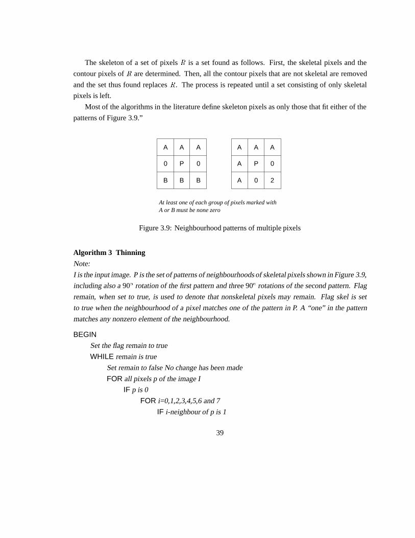
Most of the algorithms in the literature define skeleton pixels as only those that fit either of the
patterns of Figure 3.9.”
A A A
0 P 0
B B B
A A A
A P 0
A 0 2
At least one of each group of pixels marked with A or B must be none zero
Figure 3.9: Neighbourhood patterns of multiple pixels
Algorithm 3 Thinning
Note:
I is the input image. P is the set of patterns of neighbourhoods of skeletal pixels shown in Figure 3.9,
including also a90� rotation of the first pattern and three90� rotations of the second pattern. Flag
remain, when set to true, is used to denote that nonskeletal pixels may remain. Flag skel is set
to true when the neighbourhood of a pixel matches one of the pattern in P. A “one” in the pattern
matches any nonzero element of the neighbourhood.
BEGIN
Set the flag remain to true
WHILE remain is true
Set remain to false No change has been made
FOR all pixels p of the image I
IF p is 0
FOR i=0,1,2,3,4,5,6 and 7
IF i-neighbour of p is 1
39

Set flag skel to false
FOR all patterns P
IF the neighbourhood of p’s i-neighbour matches
the pattern P
Set skel to true and exit from the loop
ENDIF
ENDFOR
IF the flag skel is true
Set i-neighbour of p to 2 skeletal pixel
ELSE
Set i-neighbour of p to 3 deletable pixel
Set remain to true
ENDIF
ENDIF
ENDFOR
ENDIF
FOR all pixels p of I
IF p is 3
IF neighbourhood of p matches the pattern P
Set p to 1
ELSE
Set p to 0 and also set remain to true
ENDIF
ENDIF
ENDFOR
ENDFOR
ENDWHILE
END
Some examples of the application of the algorithm are shown in Figure 3.10.
After preprocessing, a text image is resolved into a set of subimages, each of which contains
the skeleton of a single character. The subimages are sorted into four classes, which are 32�24,
24�24, 12�24, 12�12, according to their dimensions. They may be used either as templates to be
40
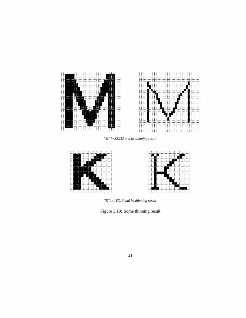
"M" in 32X32 and its thinning result
"K" in 16X16 and its thinning result
Figure 3.10: Some thinning result
41

merged into the database or as samples to be recognised in the later stage.
3.2 Template database and implementation of self-learning
A record in the template database has following data structure:
typedef struct {
unsigned long tdb_bitmap[]; /* Skeleton pattern */
float projection; /* Average vertical projection */
int ccase; /* Upper case or lower case indicator */
char name[]; /* character name */
tdb_type *next; /* Pointer to next template */
} tdb_type;
wheretdb bitmap stores the characters’ skeleton bitmap. The four databases mentioned above
have similar structures except that eachtdb bitmap has different dimensions. Even though we
have a preclassifier used which sorts all the characters images into four classes, some databases still
have too many templates. For example,tdb 24�24 usually stores normal characters and is large.
Because that large template database brings slow recognition speed, it would be better to build
some other broad classifiers. Average vertical projection AVP is another criterion of classification.
Average vertical projection of Figure 3.1 is defined as:
AV P �
PYei�Ys F �i� j�PXe
j�XsC�j�
�3�15�
where
C�j� �
�1 if
PXe
i�YsF �i� j� � 0
0 ifPXe
i�YsF �i� j� � 0
The reason why to chose AVP as a classifier is that it has light relation with various fonts and
typefaces. For example, ‘H’ in Times-Roman font has four evident hairline serifs while in Helvetica
has sanserives. See Figure 3.11.
It is known that AVP of (a) is 3.50, AVP of (b) is 3.33. We can see that AVP classifier is able to
sort characters with different fonts correctly. An argument may be made that some characters like
‘E’ have “vertical serives” which probably have a strong effect on AVP. However, in general, the
number of characters which have “vertical serives” is much fewer than the number of characters
42

(a) (b)
Figure 3.11: Two fonts of ‘H’
which have “horizontal serives” and it does not interfere the use of AVP as a broad classifier. The
calculation of AVP is performed in the preprocessing stage.
Another element of above structure isccase. The terms upper case and lower case have lost
their ordinary meanings here. Here they are specially used to tell the difference of characters which
have similar shapes but different cases like ‘O’ and ‘o’, ‘C’ and ‘c’, ‘P’ and ‘p’, etc. They almost
have the same shape after normalising. It is extremely difficult to distinguish them if there is no
auxiliary method assistance.ccase was introduced to solve this problem.
Let Ch andCw be the height and width of current character,Hpk andWpk be the height and
width of standard character in the preknowledge,Lh be the height of current line,Dlc be the
difference between top positions of current line and current character,b0� b1� b2� b3� b4 andb5 be
constants greater than 0. We have:
characterC is in upper case if
�Ch � b0Hpk� �Dlc � b1Hpk�
with preknowledge available, or
�Ch � b2Lh� �Dlc b3Lh�
without preknowledge available;
characterC is in lower case if
43

�Ch � b0Hpk� � ��Ch � b2Lh� �Dlc � b3Lh��
with preknowledge available, or
�Ch � b2Lh� � ��Ch � b0Hpk� �Dlc b1Hpk��
without preknowledge available;
characterC is in special case, i.e., ‘.’, ‘-’, ‘|’, ‘I’, ‘l’, etc., if
�Ch � b4Hpk� �Cw � b5Wpk�
with preknowledge available, or
�Ch � b6Lh� �Cw � b7Lh�
without preknowledge available.
In this systemb0 is set to 0.85,b1 0.2,b2 0.5,b3 0.15,b4 0.1,b5 0.15,b6 0.08 andb7 0.1. These
are statistical results based on the normal English printing.
As for thename in the above data structure, it is the name of current template character given by
the operator when the template database was established or expanded. When the template database
is being built, the system automatically sets up the input flag in the input area of thexocr interface
and produces a frame around the current character until the name of the character has been input by
the operator. The name is recorded intdb name. See Figure 3.12.
A similar way to add in templates is through the interactive recognition. The recognition process
stops at any sample character whose recognition is below a gate value, which is a little higher than
that in non-interactive case. The recognition process continues after the user has input the character
name. The character is remembered in the database as a new template.
After the template database has been built, an input sample can be recognised by comparing the
sample skeleton with the skeletons of the templates stored in the template database. The template
database is loaded into the memory when the system starts at the very beginning, except that it
does not exist at all, in this case, the template database can be built while interactive recognition
is running. The number of templates can be expanded at any time and the databases both inside
44

Figure 3.12: Template character input
memory and outside memory will be updated synchronously. A redundancy check is performed
when a new template is added into the database so as to keep the database as small as possible.
The templates in the database are stored in ascii code and can be modified by users. When stored
on disk, the database is compressed by adaptive Lempel-Ziv coding method, which can reduce
50-60% of textual space (see [Welch 1984]). Recognition implementation will be explained in the
next section.
3.3 Character recognition
In this stage, the features of an input character will be compared with certain templates stored in
the database. The closest match is considered the recognition result. If none of the matches is close
enough (or the difference is too big), the input character is said to be rejected.
So far, three broad classifiers are established. They are based on:
1. dimensions of characters – 32�24, 24�24, 12�24 and 12�12
45

2. character cases – upper case, lower case and special case
3. AVP
Using the three classifiers, firstly an input sample can find a set of templates to be compared
with in the database which have the same dimension and same case as the sample, and an AVP
which is in a certain range around the AVP of the templates. Secondly, a final classifier which is
based on the skeleton matching will be used on this set of templates to find out which of them is the
final result. The matching algorithm is explained below.
Let T be the set of templates in the database, it can be expressed as:T � ftkg where
k � 1� 2� 3� � � � � K�K is the total number of templates.
Eachtk in turn can be expressed as:tk � fslg wherel � 1� 2� 3� � � � � Lk� Lk is the the total
skeletal pixels number of templatetk .
F �i� j� is defined as same as equation 3.1.
Let p1 andp2 be two pixels in the two matching planes, we define:
f�p1� p2� �
�������������
W1 if p1 is in the same position ofp2
W2 if p1 is 0- 2- 4- 6-neighbour ofp2
W3 if p1 is 1- 3- 5- 7-neighbour ofp2
W4 if p1 is not N-neighbour ofp2, N = 0, 1, 2,� � � , 7
�3�16�
W1� W2 � W3 � W4
This is a simplified distance function to measure the distance betweenp1 andp2.
Let
Dk1 �
PLkl�1 f�sl� �i� j��PLk
l�1W1�3�17�
and
Dk2 �
PLkl�1 f��i� j�� sl�PLk
l�1W1�3�18�
for F �i� j� � 1.
Let
Dk � min�Dk1� Dk2� �3�19�
and
Dr � min�D1� D2� � � � � Dk� �3�20�
46

wherer � f1� 2� � � � � Kg
If D e� 0 e � 1, we say thattr is the recognition result, otherwiseF �i� j� is rejected.
The rejected characters are simply labeled with ‘[]’, the operator can easily find the places and
do necessary modification.
Algorithm 4 Recognition
Note:
Constant W1, W2, W3 and W4 have tremendous influences on the recognition result, they thus
have to be carefully chosen. The higher the difference between W1, W2, W3 and W4 is, the more
the accurate matching will be examined. If it is too high, many input characters will be rejected. If
it is too low, many characters will be recognised incorrectly. In this system they are set to 14, 10, 5
and 0 respectively. e is the rejection threshold and is set to 0.7. e1 is rejection threshold in first pass
and is set to 0.98. If the first pass of comparison cannot achieve the accuracy of e1, then second
pass is performed. avprange indicates that in which area of AVP the first pass is compared. For
example, if avprange is 0.5, then all the template whose AVP is between sample AVP� 0.5 will
be compared with. avprange is set 0.5 here. For the sake of conciseness, the attributes related to
sample precede with s; while to template with t.
BEGIN
SetDk1� Dk2� Dk� r� Dr to 0
Set pass to 0
Select a proper template database according to the sdimension
FOR all templates in the database
IF input sample and template have different case
SKIP to next template
ENDIF
IF pass is 0 and the difference of sAVP and tAVP is greater than avprange
SKIP to next template
ENDIF
IF pass is 1 and the difference of sAVP and tAVP is less than avprange
SKIP to next template
ENDIF
CalculateDk1 using equation 3.17
47
ENDFOR
FOR all templates in the database
IF t Dk1 is greater thane1
CalculateDk2 using equation 3.18
ENDIF
ENDFOR
GetDk from Dk1 andDk2 use equation 3.19
GetDr fromDk use equation 3.20
IF Dr is greater than e
Record r andDr as recognition result
ELSE
Record “rejected” in the sample data structure
ENDIF
END
3.4 Postprocessing
An interactive misspelling correcting function based on spelling check is applied in this stage in
order to increase the system performance. There are two things that may make the final recognition
result unacceptable. One comes from the rejected characters which are marked by ‘[]’. Another is
caused by the mis-recognised characters. For example, ‘l’ is recognised as ‘1’, ‘Z’ as ‘2’, etc. Both
these two case will generate misspelled words. Therefore if we can find a way to correct the wrong
words, the recognition result might be improved a lot.
Xocr provides a convenient way to do this work. It can list all the misspelled words, give
the correct suggestions and do replacement, as described in section 2.2. Figure 3.13 shows the
correction interface.
A spelling-correcting system requires the following functions:
1. A check as to whether the input word is correctly spelled or not (spelling check).
2. A search to provide likely alternative words (spelling correction) (See [Takahashi+ 1990].
Two approaches to providing these functions have been proposed. In one, the exact-match
method, candidates for the correctly spelled word are generated from an input word by using certain
48

Figure 3.13:Xocr correction interface
49

applied rules which define patterns of misspelling; these candidates are then checked to determine
whether they are in the dictionary. This method is widely used because of its simple dictionary
structure. Another method, the best match method, searches for words that are spelled similarly to
the input word. The former has a lower capability than the second method because that it is very
difficult to discover the errors not defined in the rules. A large amount of statistical data is also
needed to construct rules specific to each input method. The second approach is hardly practical
because it takes a long time to calculate the similarities between an input word and each word in
the dictionary. Also some complicated dictionary structures have to be used as well.
In the xocr system, a solution based on the best match method was developed. However,
because of the use of a hash index, the searching time is fairly short and the structure of the
dictionary is quite simple.
Xocr callsspell (See SPELL(1)) for spelling check. Sincespellis a mature text preparing tool,
there is no need to redesign such a system to pick up misspelled words.
Xocr uses a dictionary which contains more than 36,000 words, ordered by their length sequence.
A hash table consisted of first positions of words with different lengths was built in order to speed
up the searching.
In order to get an effective system, we have to make it clear which kind of misspelling we are
dealing with.
A misspelled word generated byxocr usually has following appearance:
XX � � �X �� � � �X �� � � �X
whereX represents any one in the characters set; ‘��’ indicates that a character in this position is
unknown or there are several overlapped characters missed here. Therefore, a ‘��’ might match at
least one characters in a candidate. The word can be represented as:
s1��s2� � � � � ��sn
wheres1� s2� � � � � sn are segments delimited by ‘[]’s.n is the total number of segments.
Except this case, there are few chances for misspelling by missing a character in a sample
word. Thus the problem becomes how to find candidates which have the best match of segments
s1� s2� � � � � sn in the same order as they occurred in the sample.
Assume that the length of sample isLs; let Lc1� Lc2� � � � � Lcm be the lengths of candidates,
wherem is the total number of candidates. We have:
0� Lci � Ls � L0 �3�21�
50

i � f1� 2� � � � � mg
L0 is a constant, in this systemL0 = 3.
Let M1�M2� � � � �Mn be the matched rate of the segments. The matched rate compared by
candidatesci is marked asMji� j � f1� 2� � � � � ng. A candidateck is chosen to be a correcting
suggestion if it satisfies:
ak
nXj�1
Mjk � max�a1
nXj�1
Mj1� a2
nXj�1
Mj2� � � � � am
nXj�1
Mjm� �3�22�
whereai are weights determined by difference between the two lengths:
ai � 1� a0jLci � Lsj
Lci�3�23�
i � f1� 2� � � � � mg
a0 is a constant whose value is 0.5 in the system.
As for Mji, it is the ratio between the number of matched characters in a certain range of a
candidate, and the number of all the characters in the segment. See Figure 3.14.
[] [] []
a b c d e f g h i j . . .*
a b c d g h i k
k
... *
Candidate Ci
Misspelled sampleSegment 1 Segments 2 Segment n
Figure 3.14: Matching candidates
In Figure 3.14, the darkest shadow is the overlapped area of two succeed segments in the
candidate, which is to be matched by both corresponding segments in the sample. In this system
it at most matches two characters. It means that a ‘[]’ may represent no more than two missed
characters.
The algorithm can be described as follow.
51

Algorithm 5 SpellingCorrection
Note: ci� ai andMj have the same meaning as listed above.
BEGIN
Call spell to pick up all the misspelling words
FOR each misspelling word (sample)
Dissemble the sample into segments separated by ‘[]’
Adjudge the searching area (start and end position) in the dictionary
according to the sample length by condition 3.21
FOR each candidate ci in the searching area
Calculateai using equation 3.23
CalculateMji as described above
ENDFOR
FOR each candidate
Chose the candidate with maximumMj as correction suggestion
using equation 3.22
ENDFOR
ENDFOR
END
This programme runs in the background while the interactive correcting runs in the foreground
to avoid the inconvenience brought about by the execution time.
So far thexocr realisation has been described. Some results obtained from experiments are
given in the next section to show the system profile.
52
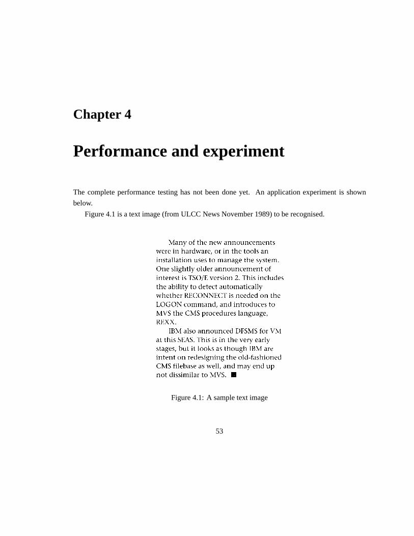
Chapter 4
Performance and experiment
The complete performance testing has not been done yet. An application experiment is shown
below.
Figure 4.1 is a text image (from ULCC News November 1989) to be recognised.
Figure 4.1: A sample text image
53

After scanning, the image can be seen in Figure 2.2, see Page 19. The scanner was set to:
Bitmap dithering patterns: bitmap
Resolution: 300 dpi
Scale factor percentage: 100
Intensity: 0
Contrast: 0
Automatic background control: no
Thexocr setting is:
Preknowledge standard width: 30
standard height: 30
offset between words: 9
Template
The fonts was adopted from X11 built in fonts library, which is named:
-adobe-times-medium-r-normal–34-240-100-100-p-170-iso8859-1
These characters were included:
A,B,C,D,E,F,G,H,I,J,K,L,M,N,O,P,Q,R,S,T,U,V,W,X,Y,Z
a,b,c,d,e,f,g,h,i,j,k,l,m,n,o,p,q,r,s,t,u,v,w,x,y,z
1,2,3,4,5,6,7,8,9,0,.,,,*,&,%,$,#,!,:,;,+,=,[,],f,g,?,/,(,)
templates number and space in the databases are shown in Table 4.1- 4.2.
Table 4.1: Templates number
Databases dimensionWithout self-learning With self-learning
32�24 2 2
24�24 61 76
12�24 23 26
12�12 2 4
Recognition result without self-learning is as follows:
54

Table 4.2: Templates space
Databases Without self-learning With self-learning
Uncompressed Compressed Uncompressed Compressed
32�24 454 298 454 298
24�24 13568 5284 16994 6489
12�24 5259 1767 5855 1883
12�12 174 129 383 240
Man[] of lhe new announcemen{s
were 1n hardware[] or ln {he lools an
ins{al1a{ion uses lo manage lhe s[]slem.
One sligh{l[] older announcemenl cf
inler[]sl is TSO/E version Z. This includes
lhe abiIil[] lo []el[]cl aulomalicall[]
whelher RECONNECT is neede[] cn lhe
LOGON ccmm[]n[][] []nd 1nlrcduces lo
MVS {he CMS procedures language[]
REXX.
IBM also announced DFSMS for VM
al lhls SEAS. This is in lhe ver[] earl[]
s{ages[] bu{ 1l looks as {hough fBM ar[]
inlenl on re[]esigning lhe ol[][]fashioned
CMS filebase as well[] an[] mav []n[] up
pcl []lss1miIar lo MVS. []
Recognition result with self-learning is as follows:
Many of the new announcements
were in hardware, or ln the tools an
instal1ation uses to manage the system.
55

One slightly older announcement of
interest is TSO/E version 2. This includes
the abiIity to detect automatically
whether RECONNECT is needed on the
LOGON command, and introduces to
MVS the CMS procedures language,
REXX.
IBM also announced DFSMS for VM
at this SEAS. This is in the very early
stages, but it looks as though fBM are
intent on redesigning the old-fashioned
CMS filebase as well, and may end up
not dissimiIar to MVS. #
Recognition result with spelling correction is as follows:
Many of the new announcements
were in hardware, or ln the tools an
installation uses to manage the system.
One slightly older announcement of
interest is TSO/E version 2. This includes
the ability to detect automatically
whether RECONNECT is needed on the
LOGON command, and introduces to
MVS the CMS procedures language,
REXX.
IBM also announced DFSMS for VM
at this SEAS. This is in the very early
stages, but it looks as though IBM are
intent on redesigning the old-fashioned
CMS filebase as well, and may end up
not dissimilar to MVS. #
System performance is listed in Table 4.3 (the speed of the Sun Sparcstation1 which was the
56

machine being used is 12.5 mips).
Table 4.3: System performance
No self-learning Self-learning Spelling correction
Total number of characters 447 447 447
Rejected number 28 0 0
Recognition rate (%) 93.7 100 100
Recognised number 319 447 447
Correct number 364 442 446
Correct rate (%) 81.43 98.88 99.78
Average matching accuracy (%) 89.9 87.5 87.5
User time (matching only) (s) 46.11 46.02 46.02
System time (s) 0.47 1.15 1.15
Time/per character (s) 0.104 0.106 0.106
57

Chapter 5
Conclusion
The development of a character recognition method using skeleton matching has been presented.
This research involved the text section method, preclassifier selection, thinning algorithm design,
template database implementation, matching strategy and spelling correction technique. An exper-
iment was made to observe the system performance. A survey of general methodology in OCR by
recent year’s research was also summarised in the beginning of this report.
Various improvement aspects might be worthwhile:
Many OCR algorithms could be processed concurrently. For example, the thinning procedure
can be applied to all the characters concurrently and the matching procedure can also be performed
on all the characters at the same time. It is probably more desirable to modify the programme
in concurrent processing environment, such as to use OCCAM language and run the system on
transputers. A limitation is that many X11 facilities will not be available if this is done
The skeleton of a character could be further processed to abstract more crucial informations, such
as start points, end points, pronounced angles or corners, the T junctions, and crossing of strokes.
These can be used as features instead of the whole skeleton in order to reduce the memory space
and accelerate the speed. However, this idea cannot be realised until a better thinning algorithm
is developed. Many thinning algorithms used today bring about lots of distortions and the crucial
points would not be very reliable.
Some other approaches like contour analysis could be combined together to increase the recogni-
tion rate. Joined and overlapped characters should be treated more earnestly and further development
is expected to separate them. Also an automatic general text analyser seems very attractive. But
58

they are expected not to conflict with the original intention that to make the system as ingenious as
possible.
59

Acknowledgements
The author is thankful to Dr. Nick Ryan, my supervisor, for the helpful guide. Thanks to PONG Man-
Chi, ZHENG Yi, FU Qiong and ZENG Guo-Rong for their help in the programming environment
and information collection. I am also grateful to the University of Kent at Canterbury for supporting
my OCR research in its Computing Laboratory.
60

References
[1] Andersson, P.L., Optical Character – a Survey,Datamation, pp.43-48, 1969
[2] Arcelli, C. and Sanniti di Baja, G., A Width-Independent Fast Thinning Algorithm,IEEE
Trans. Pattern Anal. Mach. Intel. 7, pp.463-474, 1985
[3] Arcelli, C., Pattern Thinning by Contour Tracing,Computer Graphics and Image Processing
17, pp.130-144, 1981
[4] Bakis, R, Herbst, N.M. and Nagy, G., An Experiment Study of Machine Recognition of
Handprinted Numerals,IEEE Trans. Syst. Sci. Cybernet 4, pp.119-132, 1968
[5] Bourbakis, Nikolaos G., A Parallel-Symmetric Thinning Algorithm,Pattern Recognition 22,
pp.387-396, 1989
[6] Chen, Chin-Sung and Tsai, Wen-Hsiang, A New Fast One-Pass Thinning Algorithm and its
Parallel Hardware Implementation,Pattern Recognition Letters 11, pp.471-477, 1990
[7] Chen, Yung-Sheng and Hsu, Wen-Hsing, A Comparison of Some One-Pass Parallel Thin-
nings,Pattern Recognition Letters 11, pp.35-41, 1990
[8] Chinese Information Research Center, A Report on DevelopingPrinted Chinese OCR System,
BITI Report, 1988
[9] Davis, R.H. and Lyall, J., Recognition of Handwirtten Characters – a Review,Image and
Vision Computing 4, pp.208-218, 1986
[10] Fu, K.S., et al., A Dynamic Programming Approach to Sequential Pattern Recognition,IEEE
Trans. Patt. Anal. Mach. Intel. 8, pp.313-326, 1986
61

[11] Gaillat, G. and Berthod, M., Panorama des techniques d’extraction de traits caracteristiques
en lecture optique des caracteres,Revue Tech. Thomson-CSF 11, pp.943-959, 1979
[12] Glucksman, H.A., Multicategory Classification of Patterns Represented by High-Order Vec-
tors of Multilevel Measurements,IEEE Trans. Comp. 20, pp.1593-1598, 1971
[13] Govindan, V.K. and Shivaprasad, A.P., Character Recognition a Review,Pattern Recognition
23, pp.671-683, 1990
[14] Hesketh, Richard, Tools For Document Preparation on a Graphical Workstation, UKC Doc-
ument, 1990
[15] Jeng, B.S. and Chang, G.H., A PC-Based Recognition System for Printed and Handwritten
Chinese Characters Through Pipelining Approach,Proc. of CPCOL, pp.49-53, 1988
[16] Jeng, Bor-Shenn, A Study on Optical Chinese Character Recognition,Season Journal on
Elecommunication 20, pp.1-26, 1990
[17] Jeng, Bor-Shenn, Yang, Chih-Yen and Sun, San-Wei, A Further Study on the Clustering
and Classification Algorithms for Optical Chinese Character Recognition,Season Journal on
Telecommunication 20, pp.27-42, 1990
[18] Li, Ning, A General Thinning Method for Pattern Skeleton Extraction, UKC report, 1990
[19] Lin, J.K., Jeng, B.S., et al., Recognition of Printed Chinese Characters Utilising Two Stage
Classification With Mesh And Peripheral Features,Proc. Telec. Symp. 7B-1, pp.533-537,
1987
[20] Mantas, J., An overview of Character Recognition Methodologies,Pattern Recognition 19,
pp.425-430 1986
[21] McGuinness, W.H.M., History and Computers, UKC M.Sc. Dissertation, 1990
[22] Moore, Caroline, Optical Character recognition,Library & Information Briefings, 1990
[23] Mori, K. and Masuda, I., Advancesin Recognition of Chinese characters,Proc. of 5th Int.
Conf. on Pattern Recognition, pp.692-720, 1980
62

[24] Nouboud, Fathallah and Plamondon, Rejean, On-Line Recognition of Handprinted Charac-
ters: Survey and Beta Tessts,Pattern Recognition 23, pp.1031-1044, 1990
[25] O’Gorman, Lawrence, K�K Thinning, Computer Vision, Graphics, and Image Processing
51, pp.195-215, 1990
[26] Pavlidis, Theo, Algorithms For Graphics And Image Processing, Computer Science Press,
1982
[27] Peterson, J.L., Computer Programmes For Detecting and Correcting Spelling Errors.Comm.
ACM 23, pp.676-687, 1980
[28] Rabinow, J.C., Whither OCR and Whence?Datamation, pp.38-42, 1969
[29] Rokert, H.N., Neurocomputing Picking The Human Brain,IEEE Spectrum, pp.36-41, 1988
[30] Russell, Mark,vf on-line manual, 1989
[31] Sakai, K., Hirai, S., Kawada, T., Amano, S. and Mori, K., An Optical Chinese Character
Reader,Proc. of 3rd Int. Conf. on Pattern Recognition, pp.122-126, 1976
[32] Shu, Wen-Hao, The Methodology of Printed Chinese Character Recognition,Proc. of Na-
tional Conf. on Chinese Information Processing, 1982
[33] Sinha, R.M.K., On Partitioning Dictionary For Visual Text Recognition,Pattern Recognition
23, pp.497-500, 1990
[34] Sossa, Juan Humberto, An Improved Parallel Algorithm for Thinning digital Patterns,Pattern
Recognition Letters 10, pp.77-80, 1990
[35] Stallings, W.W., Recognition of Printed Chinese Characters by Automatic Pattern Analysis,
Computer Graphics and Image Processing 1, pp.44-65 1972
[36] Stevens, M.E., Introduction to The Special Issue on Optical Character Recognition (OCR),
Pattern Recognition 2, pp.147-150, 1970
[37] Takahashi, H., Iton, N., Amano, T. and Yamashita, A., A Spelling Correction Method And
Its Application to an OCR System,Pattern Recognition 23, pp.363-377, 1990
63

[38] Tappert, Charles C., Suen, Ching Y. and Wakahara, Toru, The State of The Art in On-Line
Handwriting Recognition, IEEE Tran.Pattern Anal. Mach. Inte. 12, pp.787-808, 1990
[39] Welch, Terry A., A Technique for High Performance Data Compression,IEEE Computer 17,
pp.8-19, 1984
[40] Wells, C.J., Evett, L.J., Whitby, P.E. and Whitrow R.J., Fast Dictionary Look-Up For Con-
textual Word Recognition,Pattern Recognition 23, pp.501-508, 1990
[41] Xia, Yun, Skeletonisation Via the Realisation of the Fire Front’s Propagation and Extinction
in Digital Binary Shapes,IEEE Trans. Pattern Anal. and Mach. Intel. 11, pp.1076-1086,
1989
[42] Yin, Xiao-Feng, Yan, Chang-De and Su, Dong-Zhuang, The Feature Extraction and Distribu-
tion Analysis on The Basic Chinese Character Set, Beijing Information Technology Institute
(BITI) Report, 1986
[43] Zhang, Xin-Zhong, The Progress of Chinese Character Recognition in China,Journal of
Chinese Information Processing 1, pp.1-6, 1987
64