an explicit numerical modeling of soft body impact damage
TRANSCRIPT
Copyright © 2010 Tech Science Press CMES, vol.70, no.2, pp.191-215, 2010
An Explicit Numerical Modeling of Soft Body ImpactDamage in Metallic Airplane Structures
I. Smojver1, D. Ivancevic1 and D. Mihaljevic2
Abstract: This paper tackles the problem of numerical prediction of bird strikeinduced damage in real aeronautical structures using highly detailed finite elementmodels and modern numerical approaches. Due to the complexity of today’s aero-nautical structures, numerical damage prediction methods have to be able to takeinto account various failure and degradation models of different materials. Thework presented in this paper is focused on damage modeling in metallic items ofaeronautical structures.Abaqus/Explicit has been employed to perform geometrical and material nonlineartransient dynamic analyses. The problem of soft body impacts has been tackledby applying a hybrid Eulerian Lagrangian technique, thereby avoiding numericaldifficulties associated with extensive mesh distortion. Eulerian modeling of thebird impactor resulted in a more realistic behavior of bird material during impact.The main focus of the work presented in this paper is the application of damageprediction procedure in damage assessment of bird impact on a typical large air-liner slat structure and comparison with damage observed during exploitation of areal slat structure. Due to the high cost of gas-gun testing of aircraft components,experimental testing on the real flap structure could not have been performed. Val-idation of the hybrid formulation in solving bird strike problems has been achievedby comparison with available references.
Keywords: bird strike, Coupled Eulerian Lagrangian formulation, structural im-pact, strain rate effects, damage, aeronautical structure.
1 Introduction
Collisions with birds are becoming a growing threat to flight safety due to changesin migration routes of flocking birds [Echenfelder (2005)] and ever increasing airtraffic. The ability of critical aircraft structures to withstand foreign object impact
1 Faculty of Mechanical Engineering and Naval Architecture, University of Zagreb, Croatia2 AVL-AST d.o.o., Croatia
192 Copyright © 2010 Tech Science Press CMES, vol.70, no.2, pp.191-215, 2010
damage is regulated by certification requirements, as such impact loadings presentpotentially hazardous events for the air traffic safety. Numerical impact simulationscan supplement, or even completely replace costly gas gun experiments. In order toreduce the costs involved with assessment of bird strike resistance of critical aero-nautic components, numerical bird strike simulations are subjected to continuousimprovements. The main problem of both experimental and numerical bird strikedamage predicting methods is the realistic modeling of the impact loading. An im-portant reference in the numerical modeling of bird strikes is Willbeck (1977), inwhich several impactor material models are validated as bird replacements in gas-gun experiments. The results published in this significant reference are, althoughbeing over thirty years old, still a common starting point for scientific research inthe field of bird strike damage analysis.
Finite element analyses, based on explicit time integration schemes, enable numer-ical simulation of brief events in which large displacements, material failure andcomplex contact conditions are expected to occur. Accurate modeling of forcesand pressures during the impact is essential to correctly predict the damage causedby bird strikes. Regarding the impactor model, there are three dominant approachesin the numerical simulation of a bird in an impact event: the Lagrangian approach,hybrid Eulerian Lagrangian approaches [Zukas, Nicholas, Swift, Greszczuk, andCurran (1992)] and the Smooth Particle Hydrodynamics (SPH) method. The La-grangian approach uses traditional finite element formulation for the impactor model.A major drawback of this approach is the inability to capture extreme deformationsof bird material, as excessive element distortion prevents realistic modeling of birdmaterial motion. In order to avoid numerical instabilities caused by mesh distor-tion, special element controls have to be employed for impactor elements. Althoughsuch techniques postpone the occurrence of numerical errors, large distortion of fi-nite elements can in some impact conditions reduce the stable time increment ofexplicit analyses to an unacceptably low level. Hourglass controls have been effi-ciently employed for bird impactor modeling for example in Ianucci and Donadon(2006), Smojver and Ivancevic (2010) and Guida, Marulo, Meo, and Riccio (2008).Another method to counter problems associated with extreme element distortion isthe employment of failure criteria for impactor elements which remove heavilydistorted elements from the model when they reach a certain limit of deformation.Efficient application of this approach has been demonstrated in Airoldi and Cac-chione (2006), where an automated trial and error procedure has been employed toeliminate excessively distorted elements after premature analysis termination, andrestart the analyses without the critically distorted elements.
In hybrid approaches, the bird material flows relative to an Eulerian mesh, therebyavoiding large mesh distortion. The impacting loads are transferred to the La-
An Explicit Numerical Modeling of Soft Body Impact Damage 193
grangian mesh of the impacted structure through an Eulerian-Lagrangian couplingalgorithm [Zukas, Nicholas, Swift, Greszczuk, and Curran (1992)]. This bird strikemodeling approach has been used in e.g. Tho and Smith (2008), Lavoie, Gakwaya,Nejad Ensan and Zimcik (2007).
The SPH, a more recent approach to the bird strike modeling problem, is a meshfree method based on the Lagrangian formulation in which the finite elements havebeen replaced by a set of discrete, mutually interacting particles. Due to the factthat this approach is a mesh-less method, it is well suited for problems where occur-rence of large distortions is expected. This method has been used for fluid structureinteraction phenomena as in Campbell, Vignjevic, Patel and Milisavljevic (2009)or for impact problems as for example in Vignjevic, Reveles and Campbell (2006),Guida, Grimaldi, Marulo, Meo and Olivares (2009), Georgiadis, Gunnion, Thom-son and Cartwright (2008), and Johnson and Holzapfel (2003). The main drawbackof ALE and SPH compared to the pure Lagrangian description of the bird behavioris the increased computational time needed for such simulations, although provid-ing more numerical stability.
Here depicted work presents the improvements of the bird impact damage predict-ing procedure described in Smojver and Ivancevic (2010). The main advancementhas been made in the modeling of bird material behavior upon impact. The Abaqus’hybrid formulation - Coupled Eulerian Lagrangian (CEL) has been employed toeliminate instabilities associated with the Lagrangian bird model, as describedabove. Furthermore, the LESAD software introduced in Smojver and Ivancevic(2010), developed in order to enable analyses on reduced size finite element modelsto decrease computational costs and output file sizes, has been upgraded to includecreation of CEL models. The program also enables user friendly creation of CELmodels without the need for time consuming usage of Abaqus/CAE preprocessor.Additionally, improvements have been made in the modeling of metallic compo-nents of aeronautical structures by inclusion of strain rate effects in the dynamicbehavior of aluminum alloys. The bird strike damage prediction capability hasbeen demonstrated in this work by a comparison of numerically obtained resultswith damage reports of a bird impact on a real large airliner slat structure.
2 Impactor modeling
Due to relatively high velocities usually involved in bird strike incidents, bird re-placement materials in experimental tests include very soft materials like gelatine.This substitution is justified by the fact that stresses which occur in the bird at theimpact exceed the material strength, leading to a flow of bird material and resultingin a fluid-like behavior of the impactor. Numerical bird models are usually repre-sented by an equivalent mass of water as to replicate the fluid-like bird deformation.

194 Copyright © 2010 Tech Science Press CMES, vol.70, no.2, pp.191-215, 2010
This assumption is justified by the fact that a large percentage of the bird is made upof water. The constitutive behavior of water is modeled by equation of state (EOS)materials. Common practice in numerical bird replacement material modeling is toadditionally take into account the trapped air in the lungs and bones, thus loweringthe water density. Bird geometry has been replaced by a cylinder with hemispher-ical ends, and a length to diameter ratio of two, as this shape the most accuratelyresembles pressure time histories obtained at gas gun experiments, as explained inAiroldi and Cacchione (2006) and Johnson and Holzapfel (2003).
2.1 Equation of state
Equation of state defines the material’s volumetric strength as well as pressure vs.density ratio. The complex pressure history created after the impact of a soft bodycan be divided into three distinct stages. The first stage is characterized by the peakpressure (Hugoniot pressure) having the theoretical value
pH = ρ0US (U0)U0, (1)
with ρ0 as the material initial density, while US and U0 are the shock and impactvelocities, respectively [Wilbeck (1977]. The maximum (peak) pressure phase isfollowed by a pressure release stage. The final stage is characterized by the forma-tion of a steady flow pressure, having a constant, but much lower value
p =12
ρ0U20 . (2)
Stagnation pressure values are easily predictable, while the Hugoniot pressure de-pends on the shock velocity, which itself is a function of impact velocity. A valuableobservation from Eq. (1) and Eq. (2) is that the pressures involved in a soft-bodyimpact are solely dependent on initial density, impact and shock velocities, whilethe impactor mass does not affect the pressure values. In this work, the bird hasbeen modeled as an incompressible fluid using the linear Mie-Grüneisen equationof state [Abaqus Analysis User’s Manual (2008)]. The linear Mie-Grüneisen equa-tion (also called Us-Up equation of state) describes a linear relationship betweenthe shock and particle velocities. This relationship has the form
US = c0 + sUP, (3)
where c0 is the speed of sound in the material and s is a material constant. The finalform of pressure to density relation is determined by
p =ρ0c2
0η
(1− sη)2
(1− Γ0η
2
)+Γ0ρ0Em, (4)
An Explicit Numerical Modeling of Soft Body Impact Damage 195
where η = 1−ρ0/ρ is the nominal volumetric compressive strain, Γ0 is a mate-rial constant and Em is the internal energy per unit mass. In order to define Mie-Grüneisen EOS material in Abaqus, only four material properties need to be spec-ified - ρ0, c0 , Γ0 and s. After an extensive literature survey and rigid target birdvalidation impact analyses, it has been selected to use EOS properties, as definedin Chizari, Barrett, and Al-Hassani (2009): c0 = 1480 m / s, Γ0 = 0 and s = 0. Val-idation of EOS material properties has been performed in an impact simulation ona rigid target, as described in Smojver and Ivancevic (2010).
2.2 Lagrangian bird model
In order to prevent numerical problems which are a consequence of an excessivemesh distortion of Lagrangian impactor elements, viscous hourglass control hasbeen used. The applied element controls prevent hourglassing, a problem of firstorder reduced integration elements that can, in some loading conditions, deformwith zero strain leading to the so called zero energy modes. Viscous hourglass con-trol prevents zero energy modes by adding a viscous damping term in the elementforce calculations. It is computationally the most efficient hourglass control and issuitable in high rate dynamic and large deformation simulations [Abaqus AnalysisUser’s Manual (2008)].
2.3 Coupled Eulerian Lagrangian formulation in bird modeling
Abaqus Coupled Eulerian Lagrangian (CEL) formulation offers the ability to modelfluid-structure interaction in which the exact simulation of the fluid motion is notof primary importance. As the flow of bird material is only of secondary impor-tance in bird strike analyses, the CEL approach provides a sufficiently accurateframework to capture the fluid-like deformation of the bird impactor. The Eule-rian model in CEL analyses is usually represented by a stationary cube containingEulerian elements. Abaqus provides multi-material EC3D8R volume elements tomodel Eulerian problems, which may be completely or partially occupied by theEulerian material [Abaqus Analysis User’s Manual (2008)]. The Eulerian materialis able to move through the stationary mesh and interact with the Lagrangian fi-nite element model. The material is tracked as it flows through the mesh by meansof variable Eulerian Volume Fraction (EVF) which represents the ratio by whicheach Eulerian element is filled with material. If the volume fraction is one, the ele-ment is completely occupied by Eulerian material, contrary to the completely voidelements where the volume fraction equals zero. The Eulerian material bound-ary doesn’t have to match element geometry at any time during the analysis andhas to be recomputed in each time increment as the material flows through themesh. Abaqus/CAE provides the volume fraction tool which enables initial cal-
196 Copyright © 2010 Tech Science Press CMES, vol.70, no.2, pp.191-215, 2010
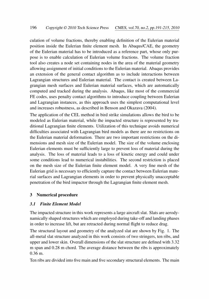
culation of volume fractions, thereby enabling definition of the Eulerian materialposition inside the Eulerian finite element mesh. In Abaqus/CAE, the geometryof the Eulerian material has to be introduced as a reference part, whose only pur-pose is to enable calculation of Eulerian volume fractions. The volume fractiontool also creates a node set containing nodes in the area of the material geometryallowing assignment of initial conditions to the Eulerian material. Abaqus providesan extension of the general contact algorithm as to include interactions betweenLagrangian structures and Eulerian material. The contact is created between La-grangian mesh surfaces and Eulerian material surfaces, which are automaticallycomputed and tracked during the analysis. Abaqus, like most of the commercialFE codes, uses penalty contact algorithms to introduce coupling between Eulerianand Lagrangian instances, as this approach uses the simplest computational leveland increases robustness, as described in Benson and Okazava (2004).
The application of the CEL method in bird strike simulations allows the bird to bemodeled as Eulerian material, while the impacted structure is represented by tra-ditional Lagrangian finite elements. Utilization of this technique avoids numericaldifficulties associated with Lagrangian bird models as there are no restrictions onthe Eulerian material deformation. There are two important restrictions on the di-mensions and mesh size of the Eulerian model. The size of the volume enclosingEulerian elements must be sufficiently large to prevent loss of material during theanalysis. The loss of material leads to a loss of kinetic energy and could undersome conditions lead to numerical instabilities. The second restriction is placedon the mesh size of the Eulerian finite element model. A very fine mesh of theEulerian grid is necessary to efficiently capture the contact between Eulerian mate-rial surfaces and Lagrangian elements in order to prevent physically unacceptablepenetration of the bird impactor through the Lagrangian finite element mesh.
3 Numerical procedure
3.1 Finite Element Model
The impacted structure in this work represents a large aircraft slat. Slats are aerody-namically shaped structures which are employed during take-off and landing phasesin order to increase lift, but are retracted during normal flight to reduce drag.
The structural layout and geometry of the analyzed slat are shown by Fig. 1. Theall-metal slat structure analyzed in this work consists of two stringers, ten ribs, andupper and lower skin. Overall dimensions of the slat structure are defined with 3.32m span and 0.28 m chord. The average distance between the ribs is approximately0.36 m.
Ten ribs are divided into five main and five secondary structural elements. The main

An Explicit Numerical Modeling of Soft Body Impact Damage 197
Figure 1: Layout of the slat structure (with upper skin removed)
ribs are manufactured from the Al 7010-T7351 alloy and differ from the secondaryribs by having greater thicknesses and local reinforcements – the thickness variesfrom 3 to 32 mm locally.
Two of the main ribs (marked 4 and 8 on Fig. 1) are designed to incorporatethe hinges used to attach the slat to the wing structure and are thus additionallystrengthened. In order to decrease the complexity of the model, the structural itemswhich connect the slat structure to the wing have been replaced by appropriateboundary conditions in the finite element simulation. The secondary ribs are man-ufactured from Al 2024-T42 alloy and are 1.8 mm thick.
The skin thicknesses are 2.1 mm and 1.9 mm for the upper and lower skin, respec-tively, while both skins are made of Al 2024-T3 alloy. The two spars are made ofAl 2024-T42 alloy and are 1.8 mm thick. The slat trailing edge is designed as asandwich structure, in order to reduce its overall mass but enable increased struc-tural stiffness. The sandwich structure consists of aluminum honeycomb core andaluminum skins, 0.8 mm and 1.6 mm thick on the upper and lower skin, respec-tively. As slat structures are most probably impacted only on the leading edge, nodamage is expected to occur on the rear slat spar. Therefore, modeling of the rearspar has been omitted in order to simplify the complex finite element model at thejoint of the slat structure and the trailing edge sandwich structure.
Finite element modeling of the slat structure has been done by combining two andthree dimensional elements, in order to avoid excessively thick shell elements. Ac-cordingly, parts of the ribs and the complete trailing edge sandwich structure have
198 Copyright © 2010 Tech Science Press CMES, vol.70, no.2, pp.191-215, 2010
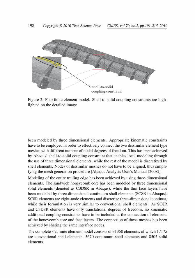
shell-to-solidcoupling constraint
Figure 2: Flap finite element model. Shell-to-solid coupling constraints are high-lighted on the detailed image
been modeled by three dimensional elements. Appropriate kinematic constraintshave to be employed in order to effectively connect the two dissimilar element typemeshes with different number of nodal degrees of freedom. This has been achievedby Abaqus’ shell-to-solid coupling constraint that enables local modeling throughthe use of three dimensional elements, while the rest of the model is discretized byshell elements. Nodes of dissimilar meshes do not have to be aligned, thus simpli-fying the mesh generation procedure [Abaqus Analysis User’s Manual (2008)].
Modeling of the entire trailing edge has been achieved by using three-dimensionalelements. The sandwich honeycomb core has been modeled by three dimensionalsolid elements (denoted as C3D8R in Abaqus), while the thin face layers havebeen modeled by three dimensional continuum shell elements (SC8R in Abaqus).SC8R elements are eight-node elements and discretize three-dimensional continua,while their formulation is very similar to conventional shell elements. As SC8Rand C3D8R elements have only translational degrees of freedom, no kinematicadditional coupling constraints have to be included at the connection of elementsof the honeycomb core and face layers. The connection of those meshes has beenachieved by sharing the same interface nodes.
The complete slat finite element model consists of 31350 elements, of which 17175are conventional shell elements, 5670 continuum shell elements and 8505 solidelements.
An Explicit Numerical Modeling of Soft Body Impact Damage 199
3.2 Material and failure models
High velocity impacts, like bird strikes, usually result with deformation rates inthe intermediate strain rate regime (maximum value of equivalent strain rate forthe analyzed cases in this work is 216 s−1). In this loading condition, like in themost of crashworthiness problems, the effects of strain rate on material behaviorare significant and cannot be neglected.
The strain rate dependency has been included for the Al 2024-T3 alloy used as aprimary material for slat skins and most of the interior structure. Generally, theyield stress depends on strain, strain rate and temperature
σ = f (ε, ε̇,T ). (5)
One of the most widely used strain-rate models in impact problems is the Cowper-Symonds law (used e.g. in Guida, Marulo, Meo and Riccio (2008) and Tho andSmith (2008)). The Abaqus/Explicit user material subroutine VUMAT has beenused to account for strain rate effects in the constitutive behavior of the Al 2024-T3alloy. The implemented constitutive model includes a Von Mieses yield criterionand an algorithm that takes into account strain rate sensitivity by enforcing theCowper-Symonds law. The elastic-plastic behavior has been defined as a powerlaw, after McCarthy, Xiao, Petrinic, Kamoulakos and Melito (2004)
σ(ε) = a+b(εp)n. (6)
The parameters a, b and n for the Al 2024-T3 alloy are taken from McCarthy,Xiao, Petrinic, Kamoulakos and Melito (2004). The mathematical description ofthe assigned hardening law has the form
σn
σy= 1+
(ε̇
D
)1/p
, (7)
where σn is the dynamic yield stress, σy is the static yield strength, and ε̇ is theequivalent strain rate. The parameters D and p of the Cowper-Symonds law for theAl 2024-T3 are taken from Guida, Marulo, Meo and Riccio (2008). Combining Eq.(6) and Eq. (7) results in the final form of hardening rule
σ(ε, ε̇) = [a+b(εp)n]
[1+(
ε̇
D
)1/p]
. (8)
All necessary parameters needed to define the constitutive behavior of the Al 2024-T3 alloy are summarized in Tab. 1.
200 Copyright © 2010 Tech Science Press CMES, vol.70, no.2, pp.191-215, 2010
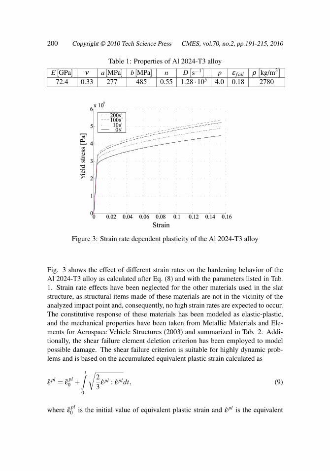
Table 1: Properties of Al 2024-T3 alloy
E [GPa] ν a [MPa] b [MPa] n D[s−1]
p ε f ail ρ[kg/m3]
72.4 0.33 277 485 0.55 1.28 ·105 4.0 0.18 2780
Figure 3: Strain rate dependent plasticity of the Al 2024-T3 alloy
Fig. 3 shows the effect of different strain rates on the hardening behavior of theAl 2024-T3 alloy as calculated after Eq. (8) and with the parameters listed in Tab.1. Strain rate effects have been neglected for the other materials used in the slatstructure, as structural items made of these materials are not in the vicinity of theanalyzed impact point and, consequently, no high strain rates are expected to occur.The constitutive response of these materials has been modeled as elastic-plastic,and the mechanical properties have been taken from Metallic Materials and Ele-ments for Aerospace Vehicle Structures (2003) and summarized in Tab. 2. Addi-tionally, the shear failure element deletion criterion has been employed to modelpossible damage. The shear failure criterion is suitable for highly dynamic prob-lems and is based on the accumulated equivalent plastic strain calculated as
ε̄pl = ε̄
pl0 +
t∫0
√23
ε̇ pl : ε̇ pldt, (9)
where ε̄pl0 is the initial value of equivalent plastic strain and ε̇ pl is the equivalent
An Explicit Numerical Modeling of Soft Body Impact Damage 201
plastic strain rate. An element is assumed to fail when the damage parameter cal-culated as
ω =ε̄
pl0 +∑∆ε̄ pl
ε̄plf
, (10)
exceeds the value of 1. In Eq. (10) ε̄plf is the strain at failure, ∆ε̄ pl is the plastic strain
increment and the summation is performed over all increments in the analysis.
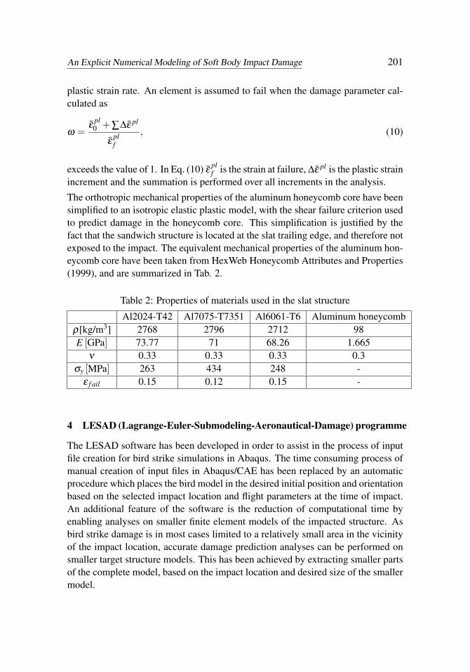
The orthotropic mechanical properties of the aluminum honeycomb core have beensimplified to an isotropic elastic plastic model, with the shear failure criterion usedto predict damage in the honeycomb core. This simplification is justified by thefact that the sandwich structure is located at the slat trailing edge, and therefore notexposed to the impact. The equivalent mechanical properties of the aluminum hon-eycomb core have been taken from HexWeb Honeycomb Attributes and Properties(1999), and are summarized in Tab. 2.
Table 2: Properties of materials used in the slat structure
Al2024-T42 Al7075-T7351 Al6061-T6 Aluminum honeycombρ[kg/m3] 2768 2796 2712 98E [GPa] 73.77 71 68.26 1.665
ν 0.33 0.33 0.33 0.3σy [MPa] 263 434 248 -
ε f ail 0.15 0.12 0.15 -
4 LESAD (Lagrange-Euler-Submodeling-Aeronautical-Damage) programme
The LESAD software has been developed in order to assist in the process of inputfile creation for bird strike simulations in Abaqus. The time consuming process ofmanual creation of input files in Abaqus/CAE has been replaced by an automaticprocedure which places the bird model in the desired initial position and orientationbased on the selected impact location and flight parameters at the time of impact.An additional feature of the software is the reduction of computational time byenabling analyses on smaller finite element models of the impacted structure. Asbird strike damage is in most cases limited to a relatively small area in the vicinityof the impact location, accurate damage prediction analyses can be performed onsmaller target structure models. This has been achieved by extracting smaller partsof the complete model, based on the impact location and desired size of the smallermodel.
202 Copyright © 2010 Tech Science Press CMES, vol.70, no.2, pp.191-215, 2010
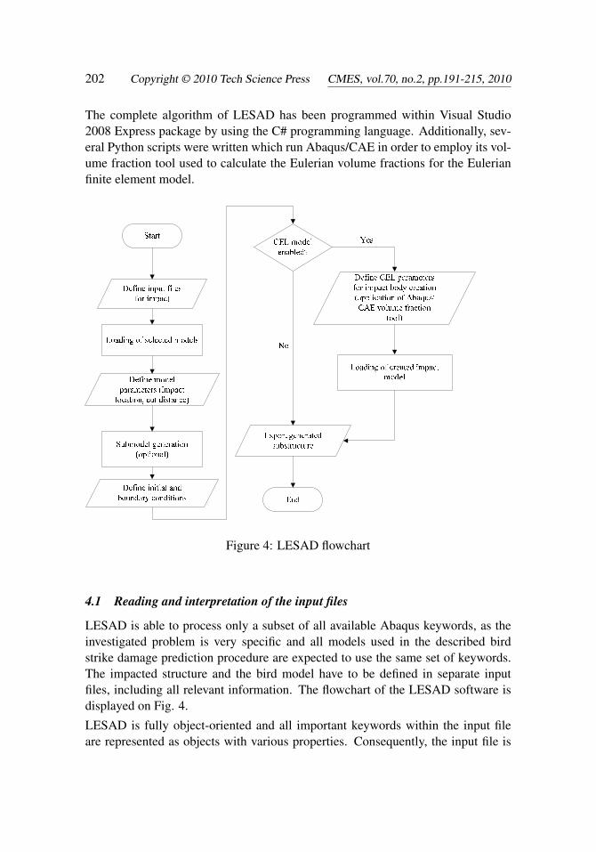
The complete algorithm of LESAD has been programmed within Visual Studio2008 Express package by using the C# programming language. Additionally, sev-eral Python scripts were written which run Abaqus/CAE in order to employ its vol-ume fraction tool used to calculate the Eulerian volume fractions for the Eulerianfinite element model.
Figure 4: LESAD flowchart
4.1 Reading and interpretation of the input files
LESAD is able to process only a subset of all available Abaqus keywords, as theinvestigated problem is very specific and all models used in the described birdstrike damage prediction procedure are expected to use the same set of keywords.The impacted structure and the bird model have to be defined in separate inputfiles, including all relevant information. The flowchart of the LESAD software isdisplayed on Fig. 4.
LESAD is fully object-oriented and all important keywords within the input fileare represented as objects with various properties. Consequently, the input file is
An Explicit Numerical Modeling of Soft Body Impact Damage 203
not just read into memory and then combined together with other input files, but islogically divided into collection of modeling primitives (nodes, elements, surfaces,etc) which then enables faster submodel generation in the next step. Error checkingwhile reading the input file is performed in such a way that unrecognized keywords,and subsequent data cards until the next known keyword is recognized, are writteninto a separate log file that serves as a necessary diagnostics tool.
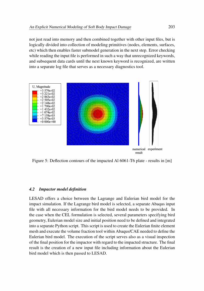
Figure 5: Deflection contours of the impacted Al 6061-T6 plate - results in [m]
4.2 Impactor model definition
LESAD offers a choice between the Lagrange and Eulerian bird model for theimpact simulation. If the Lagrange bird model is selected, a separate Abaqus inputfile with all necessary information for the bird model needs to be provided. Inthe case when the CEL formulation is selected, several parameters specifying birdgeometry, Eulerian model size and initial position need to be defined and integratedinto a separate Python script. This script is used to create the Eulerian finite elementmesh and execute the volume fraction tool within Abaqus/CAE needed to define theEulerian bird model. The execution of the script serves also as a visual inspectionof the final position for the impactor with regard to the impacted structure. The finalresult is the creation of a new input file including information about the Eulerianbird model which is then passed to LESAD.
204 Copyright © 2010 Tech Science Press CMES, vol.70, no.2, pp.191-215, 2010
4.3 Initial conditions and submodeling
LESAD offers option of two alternative sets of input flight parameters which areused to calculate impactor orientation and velocity vector components. The firstset of parameters requires definition of aircraft velocity magnitude, angle of attackand sideslip angle, while the second option requires definition of aircraft velocitymagnitude, angle of climb, heading angle and orientation in space.
In the case that the submodel generation is requested, LESAD searches through theobject collections and tags only those node-element pairs which satisfy the selectedrequirement based on the defined impact location and requested cutting length. Thealgorithm thereby removes all nodes and elements which are placed outside thedefined distance from the impact location. If the set or a surface does not containany elements or nodes, it is completely removed from the submodel definition.
4.4 Merging of the models
The final step in the impact model generation is the merging of the input files ofthe impactor and the impacted structure into a single input file which will be runthrough the Abaqus solver. As previously mentioned, all objects in LESAD containproperties and subroutines which write all relevant information from the object intothe final input file using Abaqus input file structure. As a result, new input file isgenerated that contains information associated with the bird model and impactedstructure, instance definitions within the assembly definition, information aboutused materials, initial conditions, analysis specification etc.
5 Verification
Application of the CEL formulation to numerically solve bird strike problems hasbeen validated by a comparison with published results of gas-gun experiments onaluminum Al 6061-T6 plates. The experimental results, available in Welsh andCentoze (1986), evaluate the suitability of substitute gelatine impactors as bird re-placements in experiments. Both impactors, real birds and gelatine replacements,have weight of 4 lb (1.81 kg), since large passenger aircraft must withstand an im-pact of such a bird in order to fulfill certification requirements specified in FAR25.571, after Georgiadis, Gunnion, Thomson and Cartwright (2008). The dimen-sions of the target plate are 550 x 550 x 6.35 mm. The impacted plate is bolted to asteel support plate with the 0.4064 m diameter opening. The aluminum plate is dis-cretisized by 520 S4R shell elements, as shown in Fig. 5. The steel support framehas been replaced by the corresponding boundary conditions, as the nodes outsidethe opening had restrained displacements in the thickness direction. Furthermore,six nodes had all six degrees of freedom restricted as to replicate the effect of a
An Explicit Numerical Modeling of Soft Body Impact Damage 205
bolted joint. Dimensions of the Eulerian part are 1.4 x 1.4 x 0.5 m in order to en-sure that the bird material doesn’t protrude outside the Eulerian finite element gridconsisting of 980000 elements. A very fine mesh of Eulerian elements is neededto efficiently capture contact conditions between the Lagrangian plate and Eulerianmaterial (as explained in Section 2.3).
0,3
28°
1
2
3
Eulerian model
bird material
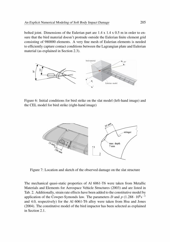
Figure 6: Initial conditions for bird strike on the slat model (left-hand image) andthe CEL model for bird strike (right-hand image)
Figure 7: Location and sketch of the observed damage on the slat structure
The mechanical quasi-static properties of Al 6061-T6 were taken from MetallicMaterials and Elements for Aerospace Vehicle Structures (2003) and are listed inTab. 2. Additionally, strain rate effects have been added to the constitutive model byapplication of the Cowper-Symonds law. The parameters D and p (1.288 · 106s−1
and 4.0, respectively) for the Al 6061-T6 alloy were taken from Hsu and Jones(2004). The constitutive model of the bird impactor has been selected as explainedin Section 2.1.
206 Copyright © 2010 Tech Science Press CMES, vol.70, no.2, pp.191-215, 2010
t= 1 ms
t= 2 ms
t= 3 ms
t= 4 ms
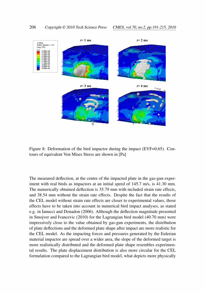
Figure 8: Deformation of the bird impactor during the impact (EVF=0.65). Con-tours of equivalent Von Mises Stress are shown in [Pa]
The measured deflection, at the centre of the impacted plate in the gas-gun exper-iment with real birds as impactors at an initial speed of 145.7 m/s, is 41.30 mm.The numerically obtained deflection is 35.79 mm with included strain rate effects,and 38.54 mm without the strain rate effects. Despite the fact that the results ofthe CEL model without strain rate effects are closer to experimental values, thoseeffects have to be taken into account in numerical bird impact analyses, as statede.g. in Ianucci and Donadon (2006). Although the deflection magnitude presentedin Smojver and Ivancevic (2010) for the Lagrangian bird model (40.70 mm) wereimpressively close to the value obtained by gas-gun experiments, the distributionof plate deflections and the deformed plate shape after impact are more realistic forthe CEL model. As the impacting forces and pressures generated by the Eulerianmaterial impactor are spread over a wider area, the slope of the deformed target ismore realistically distributed and the deformed plate shape resembles experimen-tal results. The plate displacement distribution is also more circular for the CELformulation compared to the Lagrangian bird model, what depicts more physically

An Explicit Numerical Modeling of Soft Body Impact Damage 207
realistic behavior. The improved similarity of impacted plate shape is a direct resultof the physically enhanced modeling of fluid-like bird behavior by the Eulerian birdmaterial model. The stability of the analysis is also improved, as the CEL modeldoesn’t suffer from significant mesh distortion. However, the main disadvantage ofthe CEL model, compared to the Lagrangian bird model, is the much higher com-putational time due to the very fine mesh required for an Eulerian model. Fig. 5shows results of the CEL bird impact validation including strain rate effects in theimpacted plate.
6 Results
In order to demonstrate the capabilities of the applied damage prediction proce-dure, an actual impact on the slat has been simulated. The information about thedamage on the slat structure has been taken from Internal written communicationwith Croatia Airlines (2009). Regrettably, important input variables such as initialvelocity, aircraft angle of attack and bird mass are not exactly known. However, itis known that the investigated bird strike occurred during the landing phase of theflight. This information enables estimation of velocity, aircraft attitude and slat de-flection angles, as those parameters are identifiable for a particular medium rangepassenger aircraft. The mass of the impacting bird has been assumed to be 0.45kg, based on the fact that most of the bird strikes in the operating environment ofthe particular aircraft involve collisions with crows, as stated in Internal writtencommunication with Croatia Airlines (2009). The average mass of a crow has beentaken from Lawrence (1973). Taking into account the approximate landing glideslope, wing incidence angle and aircraft pitch angle, the angle of attack (the an-gle between the chord line of the wing and the free airstream velocity) has beenassumed to be 15˚. The slat has been assumed to be in the medium deflection posi-tion (-18˚), resulting in a total angle of attack of -3˚ with regard to the slat referenceplane, as illustrated by Fig. 6, left-hand image. Additionally, the initial velocityvector is deflected by 28˚ with regard to the longitudinal axis of the slat as to takeinto account the sweep angle of the wing.
Furthermore, bird velocity has been neglected and the bird model longitudinal axisis parallel to the vector of the airflow. The CEL model for this analysis is shown onFig. 6, right-hand image. The volume containing Eulerian elements is representedby a cube having dimensions 1 x 1 x 1 m. The element length is 12 mm, resultingin 571787 ECD8R elements.
Fig. 7 illustrates a sketch of the observed damage caused by the collision withthe bird. The bird impacted between ribs number 2 and 3 (as explained by Fig.1) causing deformation of the upper skin with a maximum depth of 7 mm. Nopenetration of the slat skin has been observed. Variation of initial velocity magni-
208 Copyright © 2010 Tech Science Press CMES, vol.70, no.2, pp.191-215, 2010
tude, until acceptable match of numerically predicted and observed damaged stateshas been achieved, revealed that the initial velocity has been approximately 90 m/s(324 km/h) what corresponds to the usual flight parameters in this phase of theflight. During the variation of the initial impactor velocity, all other input variableshave been held constant, having values as previously explained. All results on theslat model in this work have been calculated for an initial velocity of 90 m/s.
Deformation of the Eulerian bird impactor at particular time measured in [ms] isshown on Fig. 8. The advantages of the CEL formulation compared to the pure La-grangian approach, presented in Smojver and Ivancevic (2010), are clearly notice-able, as the Eulerian bird model efficiently captures extreme deformation problems.On the other hand, application of the Lagrange impactor model has restrictions onthe highest velocity at which the bird finite element model can be examined. Thecritical impact velocity magnitude for the Lagrangian bird model is approximately150 m/s, depending on the target geometry and attitude of the impactor relative tothe target. Further increases of the initial velocity can result in numerical instabili-ties and errors associated with finite element distortion, as observed by the authorsof this paper.
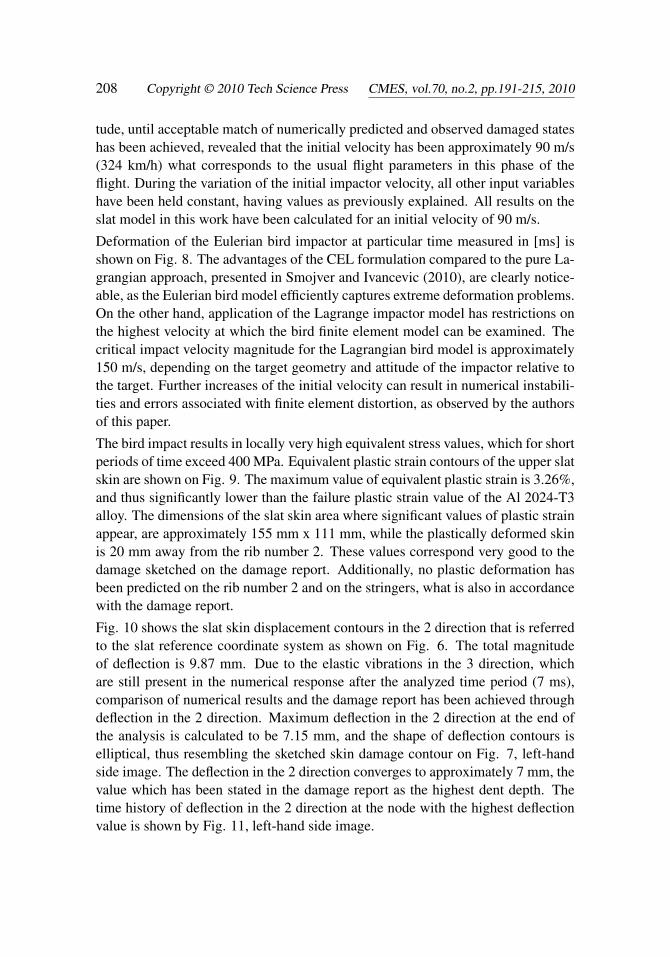
The bird impact results in locally very high equivalent stress values, which for shortperiods of time exceed 400 MPa. Equivalent plastic strain contours of the upper slatskin are shown on Fig. 9. The maximum value of equivalent plastic strain is 3.26%,and thus significantly lower than the failure plastic strain value of the Al 2024-T3alloy. The dimensions of the slat skin area where significant values of plastic strainappear, are approximately 155 mm x 111 mm, while the plastically deformed skinis 20 mm away from the rib number 2. These values correspond very good to thedamage sketched on the damage report. Additionally, no plastic deformation hasbeen predicted on the rib number 2 and on the stringers, what is also in accordancewith the damage report.
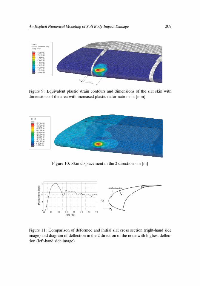
Fig. 10 shows the slat skin displacement contours in the 2 direction that is referredto the slat reference coordinate system as shown on Fig. 6. The total magnitudeof deflection is 9.87 mm. Due to the elastic vibrations in the 3 direction, whichare still present in the numerical response after the analyzed time period (7 ms),comparison of numerical results and the damage report has been achieved throughdeflection in the 2 direction. Maximum deflection in the 2 direction at the end ofthe analysis is calculated to be 7.15 mm, and the shape of deflection contours iselliptical, thus resembling the sketched skin damage contour on Fig. 7, left-handside image. The deflection in the 2 direction converges to approximately 7 mm, thevalue which has been stated in the damage report as the highest dent depth. Thetime history of deflection in the 2 direction at the node with the highest deflectionvalue is shown by Fig. 11, left-hand side image.
An Explicit Numerical Modeling of Soft Body Impact Damage 209
(Avg: 75%)
SNEG, (fraction = -1.0)
SDV1
+0.000e+00+2.718e-03+5.436e-03+8.154e-03+1.087e-02+1.359e-02+1.631e-02+1.902e-02+2.174e-02+2.446e-02+2.718e-02+2.990e-02+3.261e-02
20155
111
Figure 9: Equivalent plastic strain contours and dimensions of the slat skin withdimensions of the area with increased plastic deformations in [mm]
U, U2
-7.256e-04-6.929e-05+5.870e-04+1.243e-03+1.900e-03+2.556e-03+3.212e-03+3.869e-03+4.525e-03+5.181e-03+5.838e-03+6.494e-03+7.150e-03
Figure 10: Skin displacement in the 2 direction - in [m]
Figure 11: Comparison of deformed and initial slat cross section (right-hand sideimage) and diagram of deflection in the 2 direction of the node with highest deflec-tion (left-hand side image)
210 Copyright © 2010 Tech Science Press CMES, vol.70, no.2, pp.191-215, 2010
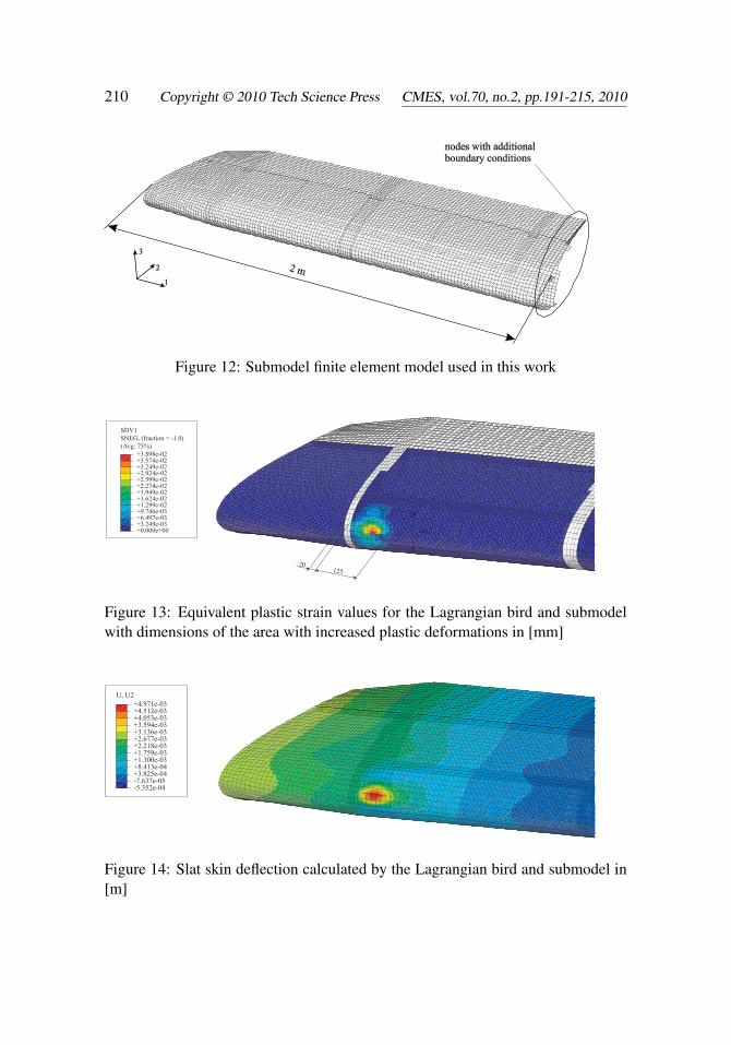
Figure 12: Submodel finite element model used in this work
(Avg: 75%)
SNEG, (fraction = -1.0)
SDV1
+0.000e+00+3.249e-03+6.497e-03+9.746e-03+1.299e-02+1.624e-02+1.949e-02+2.274e-02+2.599e-02+2.924e-02+3.249e-02+3.574e-02+3.898e-02
20125
95
Figure 13: Equivalent plastic strain values for the Lagrangian bird and submodelwith dimensions of the area with increased plastic deformations in [mm]
U, U2
-5.352e-04-7.637e-05+3.825e-04+8.413e-04+1.300e-03+1.759e-03+2.218e-03+2.677e-03+3.136e-03+3.594e-03+4.053e-03+4.512e-03+4.971e-03
Figure 14: Slat skin deflection calculated by the Lagrangian bird and submodel in[m]
An Explicit Numerical Modeling of Soft Body Impact Damage 211
t= 1 ms
t= 2 ms
(Avg: 75%)
SNEG, (fraction = -1.0)
S, Mises
+0.000e+00+3.333e+07+6.667e+07+1.000e+08+1.333e+08+1.667e+08+2.000e+08+2.333e+08+2.667e+08+3.000e+08+3.333e+08+3.667e+08+4.000e+08
t= 3 ms
t= 4 ms
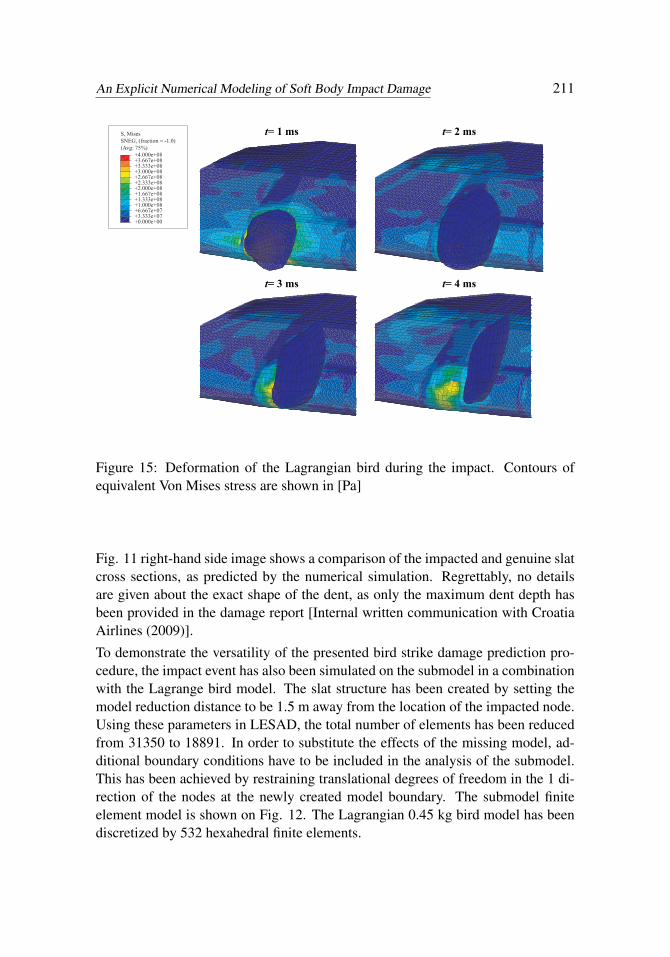
Figure 15: Deformation of the Lagrangian bird during the impact. Contours ofequivalent Von Mises stress are shown in [Pa]
Fig. 11 right-hand side image shows a comparison of the impacted and genuine slatcross sections, as predicted by the numerical simulation. Regrettably, no detailsare given about the exact shape of the dent, as only the maximum dent depth hasbeen provided in the damage report [Internal written communication with CroatiaAirlines (2009)].
To demonstrate the versatility of the presented bird strike damage prediction pro-cedure, the impact event has also been simulated on the submodel in a combinationwith the Lagrange bird model. The slat structure has been created by setting themodel reduction distance to be 1.5 m away from the location of the impacted node.Using these parameters in LESAD, the total number of elements has been reducedfrom 31350 to 18891. In order to substitute the effects of the missing model, ad-ditional boundary conditions have to be included in the analysis of the submodel.This has been achieved by restraining translational degrees of freedom in the 1 di-rection of the nodes at the newly created model boundary. The submodel finiteelement model is shown on Fig. 12. The Lagrangian 0.45 kg bird model has beendiscretized by 532 hexahedral finite elements.
212 Copyright © 2010 Tech Science Press CMES, vol.70, no.2, pp.191-215, 2010
As illustrated by Fig. 13 and Fig. 14, the combined application of the Lagrangianbird model and the submodeling approach is not completely able to replicate thedamage contours and output values calculated by the CEL formulation on the com-plete flap model. The magnitude of equivalent plastic strain is 3.90 % (opposed to3.26%), and the deflection in the 2 direction is 4.97 mm (compared to 7.15 mm).The calculated dimensions of the area having increased plastic deformation are ap-proximately 125 x 95 mm (contrary to 155 x 111 mm). Fig. 14 shows high valuesof deflection near the end of the slat structure (rib number 1), which are a result ofthe global vibration of the slat model still present at the end of the analysis.
The impact of the Lagrangian bird on the slat submodel is illustrated by Fig. 15.The deformation of the impactor finite element mesh reveals the greatest disadvan-tage of this bird modeling approach. Despite utilizing the same constitutive model,the Lagrangian impactor is not able to effectively replicate the extreme deforma-tions needed to illustrate real bird behavior during the impact. Consequently, theLagrangian impactor is not able to correctly transfer the impacting loads on the slatstructure, leading to an underestimation of deflection magnitudes. This effect isthe least obvious at impact conditions in which the initial velocity vector is perpen-dicular to the target but gains increased importance as the impact becomes moreoblique. This explains the good results obtained by the Lagrangian bird modelin Section 5, where the bird impacts normal to the target plate. As the impact onthe streamlined slat structure significantly differs from perpendicular impact condi-tions, the effect of unrealistic impactor behavior results in poor match with resultsobtained by the CEL model.
Despite relatively poor match with the observed damage from the damage reports,the combination of the submodeling approach and the Lagrangian bird model is acomputationally very efficient method to get a fast insight in the damaging processduring a bird strike on complicated structural finite element models. The combinedusage of the two different impactor models can thus be regarded as supplementarymethods, as the pure Lagrangian formulation can be used to estimate unknown ini-tial conditions which are then used as input variables for the hybrid (CEL) approachto calculate more realistic results. The complete analysis on the substructure modelhas been performed in 30 minutes, compared to approximately 8 hours for the CELformulation on the complete slat model. The analyses have been executed on aneight-core desktop workstation. The effect on computational time using the sub-modeling approach and the Lagrangian impactor model is roughly proportional tothe reduction in the number of finite elements. The combination of the Eulerian im-pactor and submodeling approach is also possible, but the effect on computationaltime reduction is negligible as the increased computational time in CEL analyses iscaused by the large number of Eulerian elements.
An Explicit Numerical Modeling of Soft Body Impact Damage 213
7 Conclusions
This paper demonstrates the enhancements in the bird strike damage predictionprocedure compared to the results presented in the previous paper [Smojver andIvancevic (2010)]. The main improvement has been accomplished by replacing theLagrange bird model with the Eulerian bird model, which has been achieved by uti-lizing Abaqus’ Coupled Eulerian Lagrangian technique. This modeling techniqueenables better capturing of the fluid-like bird behavior upon impact in the velocityrange at which bird strikes usually occur. The fact that the Eulerian model doesn’tsuffer from numerical instabilities caused by extreme material deformation, im-proves numerical stability of the analysis and enables more realistic prediction ofdamage on the impacted structure. The submodeling procedure presented in Smo-jver and Ivancevic (2010) has been further developed in order to be able to generateCEL models without the time-consuming usage of Abaqus/CAE. The combinationof the pure Lagrangian approach to the bird strike problem and the submodelingprocedure is a computationally very cost-efficient method to get insight in the dam-age process, although the accuracy of such analyses is questionable. This com-bination can be regarded as a preceding step to the CEL simulation, since initialconditions (impact location, initial velocity, impactor attitude etc.) can be quicklypredicted.
As the main focus of the presented work is damage prediction in metallic aeronau-tical structures, strain rate effects in the constitutive model of aluminum alloys havebeen included in the analyses. These effects must not be neglected in bird strikesimulations as the response of aluminum alloys at increased strain rates greatlydiffers from the quasi-static response. Without inclusion of strain rate effects, thecalculated maximum deflection in the 2 direction for the CEL model and completeslat model is 10.34 mm (compared to 7.15 mm with inclusion of strain rate effects).These results clearly indicate the importance of inclusion of strain rate effects in thebehavior of metallic structural items during impacts in the medium velocity range.
Acknowledgement: This research has been financially supported by the Ministryof Science, Education and Sports, Republic of Croatia through the scientific project“Numerical Modelling of Nonisotropic Continua” and Technological Project “Nu-merical Modelling of Impact Damage in Aeronautical Structures”. The authorswould also like to express their gratitude to Dr.Sc. Milan Vrdoljak, who developedthe flight mechanics subroutines for LESAD.
References
Abaqus Analysis User’s Manual (2008), Version 6.8. Dassault Systémes.
214 Copyright © 2010 Tech Science Press CMES, vol.70, no.2, pp.191-215, 2010
Airoldi, A.; Cacchione, B. (2006): Modelling of impact forces and pressures inLagrangian bird strike analyses. Int. J. Imp. Eng., vol. 32, pp. 1651-1677.
Benson, D.J.; Okazava S. (2004): Contact in a multi-material Eulerian finite ele-ment formulation, Comp. Methods Appl. Mech. Eng., vol. 193, pp. 4277 - 4298.
Campbell, J.C.; Vignjevic, R.; Patel, M.; Milisavljevic, S. (2009): Simulation ofwater loading on deformable structures using SPH. CMES: Computer Modeling inEngineering & Sciences, vol. 49, no. 1, pp. 1–22.
Chizari, M.; Barrett, L.M.; Al-Hassani, S.T.S (2009): An explicit numericalmodelling of the water jet tube forming. Comp. Mater. Sci., vol. 45, pp. 378-384.
Echenfelder, P.F. (2005): High speed flight at low altitude: Hazard to ComercialAviation?. Birdstrike Commitee Proceedings.
Georgiadis, S; Gunnion A.J.; Thomson, R.S.; Cartwright, B.K. (2008): Bird-strike simulation for certification of the Boeing 787 composite moveable trailingedge. Compos. Struct., vol. 86, pp. 258-268.
Guida, M.; Grimaldi, S.; Marulo, F.; Meo, M.; Olivares, G. (2009): Bird Impacton Leading Edge Wing with SPH Formulation. 17th International Conference onComposite Materials.
Guida, M.; Marulo, F.; Meo, M.; Riccio, M. (2008): Analysis of Bird Impact ona Composite Tailplane Leading Edge. Appl. Compos. Mater., vol.15, pp. 241 –257.
Hanssen, A.G.; Girard, Y.; Olovsson, L.; Berstad, T.; Langseth, M. (2006): Anumerical model for bird strike of aluminium foam-based sandwich panels. Int. J.Imp. Eng., vol. 32 pp. 1127-1144.
HexWeb Honeycomb Attributes and Properties (1999.), Hexcel Composites.
Hsu, S.S.; Jones, N. (2004): Dynamic axial crushing of aluminium alloy 6063 -T6circular tubes. Lat. Am. J. Solids Struct., vol. 3, pp. 277-296.
Ianucci, L.; Donadon, M. (2006): Bird Strike Modeling Using a New WovenGlass Failure Model. 9th International LS-DYNA Users Conference.
Internal written communication with Croatia Airlines (2009).
Johnson, A.F.; Holzapfel, M. (2003): Modelling soft body impact on compositestructures. Compos. Struct., vol. 63, pp. 103-113.
Lavoie, M.A.; Gakwaya, A.; Nejad Ensan, M.; Zimcik, D.G. (2007): Review ofexisting numerical methods and validation procedure available for bird strike mod-eling. International Conference on Computational & Experimental Engineeringand Sciences.
Lawrence, J.H. (1973): Windshield Bird Strike Structure Design Criteria. Air

An Explicit Numerical Modeling of Soft Body Impact Damage 215
Force Flight Dynamics Laboratory, Technical report AFFDL-TR-73-103.
McCarthy, M.A.; Xiao, J.R.; Petrinic, N.; Kamoulakos, A.; Melito, V. (2004):Modelling of Bird Strike on an Aircraft Wing Leading Edge Made from Fibre MetalLaminates – Part 1: Material Modelling. Appl. Compos. Mater., vol. 11, pp. 295 –315.
Metallic Materials and Elements for Aerospace Vehicle Structures MIL-HDBK-5J (2003), Department of Defence Handbook, Washington, DC.
Smojver, I; Ivancevic, D. (2010): Numerical simulation of bird strike damageprediction in airplane flap structure. Compos. Struct., vol. 92, pp. 2016 - 2026.
Tho, C.H.; Smith, M.R. (2008): Accurate bird strike simulation methodology forBA609 tiltrotor. Presented at the American helicopter society 64th annual forum.
Vignjevic, R.; Reveles, J.R., Campbell, J. (2006): SPH in a total Lagrangianformalism. CMES: Computer Modeling in Engineering & Sciences, vol. 14, no. 3,pp. 181–198.
Welsh, C.J.; Centoze, V. (1986): Aircraft transparency testing - artificial birds.Arnold Engineering Development Center, Report AEDC-TR-86-2.
Wilbeck, J.S. (1977): Impact behavior of low strength projectiles. Air Force Ma-terials Laboratory, Technical Report AFML-TR-77-134.
Zukas, J.A.; Nicholas, T.; Swift, H.F.; Greszczuk, L.B.; Curran, D.R. (1992):Impact Dynamics. Krieger Publishing Company.
