an experimental study of the effect of wake passing on ... · an experimental study of the effect...
TRANSCRIPT

NASA Technical Memorandum 107425
/W-o
An Experimental Study of the Effect ofWake Passing on Turbine Blade Film Cooling
James D. Heidmann and Barbara L. Lucci
Lewis Research Center
Cleveland, Ohio
Eli Reshotko
Case Western Reserve UniversityCleveland, Ohio
Prepared for the42nd Turbo Expo
sponsored by the American Society of Mechanical EngineersJune 2-5, Orlando, Florida, 1997
National Aeronautics and
Space Administration
https://ntrs.nasa.gov/search.jsp?R=19970012908 2018-05-29T01:11:24+00:00Z


AN EXPERIMENTAL STUDY OF THE EFFECT OF WAKE PASSING ON
TURBINE BLADE FILM COOLING
James D. HeidmannBarbara L. Lucci
NASA Lewis Research CenterCleveland, Ohio
Eli ReshotkoCase Western ReseFve University
Department of Mechanical and Aerospace EngineeringCleveland, Ohio
ABSTRACT
The effect of wake passing on the showerhead film cooling
performance of a turbine blade has been investigated experimentally.
The experiments were performed in an annular turbine cascade with an
upstream rotating row of cylindrical rods. Nickel thin-film gauges
were used to determine local film effectiveness and Nusselt number
values for various injectants, blowing ratios, and Stronhal numbers.
Results indicated a reduction in film effectiveness with increasing
Strouhal number, as well as the expected increase in film effectiveness
with blowing ratio. An equation was developed to correlate the span-
average film effectiveness data. The primary effect of wake
unsteadiness was found to be correlated by a streamwise-constant
decrement of 0.094-St. Steady computations were found to be in
excellent agreement with experimental Nusselt numbers, but to
overpredict experimental film effectiveness values. This is likely due
to the inability to match actual hole exit velocity profiles and the
absence of a credible turbulence model for film cooling.
NOMENCLATURE
C model coefficient
c blade chord
D cylindrical rod diameter
d cooling hole diameter
h heat transfer coefficient
k thermal conductivity
L cooling hole length
M blowing ratio
N rotor speed in rpm
n number of rods in rotor
Nu Nusselt number
q" heat flux per unit area
S effective slot width
St Strouhal number
T temperature
V velocity
x streamwise distance from leading edge
y+ dimensionless distance from wall
11 film effectiveness
p density
Subscriptsc coolant conditions
f film conditions
r recovery conditions
w wall conditions with heating
oo freestream conditions
INTRODUCTION
As a result of efforts to improve turbine engine performance,
turbine inlet temperatures have increased dramatically over the past 50
years. Current turbine inlet temperatures are approaching 2000 K,while the best available metallic turbine materials can withstand a
maximum temperature of only about 1300 K. When internal cooling
alone is inadequate, film cooling must be employed. In film cooling,
the coolant air is discharged through small holes in the turbine surface
to form a protective film between the turbine blade and the hot
combustor discharge gas.
The flow in turbomachinery blade rows is inherently unsteady due
to the relative motion of adjacent blade rows. Wake passing from
upstream blade rows causes periodic fluctuations in the magnitude and
relative direction of the flow velocity in downstream blade rows.
Precisely modeling a turbomachinery flow field thus requires inclusion
of the time-varying quantities. However, due to the complexity of the
unsteady flow field, the design of turbine film cooling schemes has
tended to rely on steady databases.
Because of its importance in turbine design, there has been much
investigation into the behavior of turbine film cooling flows. Goldstein
(1971) reviewed the early research in the film cooling arena. This

reviewconsolidatedflatplateexperimentsofvariousholegeometriesandblowingparameters,andsummarizedanalyticalsolutionsfortwo-dimensionalslotinjection.Theexperimentalstudiestypicallyhadlongfilmholes(L/dgreaterthan10.0).MorerecentsteadyfilmcoolingresearchissummarizedbyHeidmann(1996).ThemorerecentstudiesgenerallyconsiderL/dvaluesmoretypicalofturbineblades(between2.0and4.0),aswellasactualbladeprofiles.
Relativelylessworkhasbeendoneontheimpactofunsteadinessonfilmcoolinginaturbineblade.Rigbyetal.(1990)usedarotatingwheelwakegeneratorwithcylindricalbarstomodelinletguidevanewakesandshockwavesundertransonicflowconditions.Thetestbladewasfilmcooledonboththesuctionandpressuresides.Themaineffectof thewakepassingwasareductionin effectivenesscausedbyenhancedfilmmixing,andtheshockpassingeffectwasfoundtoproducelargefluctuationsintheheattransferrate.Ouetat.(1994)andMehendaleetel.(1994)usedanexperimentalapproachsimilartoRigbyetal (1990),exceptwithadifferentbladeprofile,subsonicflow,andincludingshowerheadcooling.BothairandCO2injectionwereemployedfordifferentdensityratios.Ouetat.(1994)foundthatincreasingwakepassingfrequencyincreaseslocalNusseltnumbersforallblowingratios,butthiseffectis reducedathigherblowingratios.Mehendaleetat.(1994)foundthatanincreaseinwakepassingfrequencycausesadecreaseinfilmeffectivenessovermostofthebladesurfaceforallcasesconsidered.Funazakietat.(1996)usedarotatingwheelwakegeneratorwithcylindricalbarsupstreamofashowerhead-cooledbluntbody.Heatedairwasusedastheinjectant.Increasingwakepassingfrequencywasfoundto reducefilmeffectiveness,especiallyatlowerblowingratioswheretheinfluenceofthewakeonthelowmomentumfilmisstrongest.Thewakeeffectwasreducedasfree-streamturbulenceincreased.
Severalstudieshaveinvestigatedfilmcoolingperformanceonaturbinebladeinanactualrotatingturbinestageenvironment.Dringetel.(1980)studiedfilmcoolingperformanceonalargescalemodelofahighpressureturbinefirststage.Coolantwasinjectedfromasingleholeonboththepressureandsuctionsidesoftherotorblade.Densityratiosfrom1.0to4.0wereinvestigatedandflowvisualizationstudiesshowedradialmigrationofthecoolant,especiallyonthepressureside.Themigrationwasfoundtoberelativelyinsensitivetothecoolantproperties.Filmeffectivenessprofilesweremeasureddownstreamoftheholes.Thesuctionsurfaceprofileswerefoundto correlatewellwithfiatplatedata,whilethepressuresurfacefilmeffectivenesswassignificantlyreduced.Takeishietel. (1992)alsomeasuredfilmcoolingeffectivenessforarotatingturbineblade.Inthiscase,thebladehadarealisticcoolinggeometrywithshowerhead,pressure,andsuctionsurfacerowsof coolingholes.Theresultsof Dringetat.(1980)werecorroborated,asthepressuresurfacefilmeffectivenesswasfoundtodecreaserelativetocascadetestsduetotheradialflowandconcavecurvature.Thesuctionsurfacefilmeffectivenesswasingoodagreementwiththestationarybladetestsexceptfardownstreamwhereenhancedmixingreducedthefilmeffectiveness.AbhariandEpstein(1992)usedashortdurationturbinetestfacilitytoagainstudyafilm-cooledrotatingbladein a turbinestageenvironment.Thecoolingarrangementconsistedofthreerowsofcoolantholesonthepressuresurfaceandtwoonthesuctionsurface,butnoshowerheadcooling.UnlikeDringetal.(1980)andTakeishietat.(1992),thisstudyconsideredtransonicflow. Thisintroducedunsteadyshockpassinginadditiontowakepassingasunsteadyeffects.Forthese
tests,thesuctionsurfacehada 12percentdecreaseinheattransfer,whilethepressuresurfacehada5percentincreaserelativetocascadetests.Theunsteadyeffectswereattributedtocoolantflowratechangescausedprimarilybyshockpassingpressurefluctuations.
Unsteadynumericalsimulationsforanentirefilm-cooledturbinestagearescarceduetothelargecomputationaltimeassociatedwithcapturingboththesmalltimescalesofbladepassingandthesmalllengthscalesoffilmcoolingandheattransfer.However,DorneyandDavis(1992)showedthatsuchasimulationcouldbeachievedusingatime-accurateNavier-Stokessolver.Thecomputationalconstraintslimitedthesimulationtoonlytwogridpointsperfilmhole,solocaleffectsduetoholeexitprofilecouldnotbemodeled.
Althoughrecentresearchhasbeguntofocusontheunsteadyflowenvironment,themajorityof researchon film coolantflowhasconsideredtheturbinefreestreamflowtobesteady.Studiesoffilmcooledturbinestagesincludeunsteadiness,butlacktheabilitytovarytheunsteadyparameter.Cylindricalwakeexperimentssolvethisproblem,buthavenotsoughttoresolvespanwiseandtimevariationsto isolatetheimportantphysicalphenomenaassociatedwithfilmcoolantflow.Thepresentstudyalmstoinvestigatetheeffectofflowunsteadinesson turbinefilm coolingin a moredetailedandfundamentalmanner.Showerheadcoolingischosenbecauseofthelargertemporalfluctuationsin staticpressurein theleadingedgeregionandtheeffectofincidenceonshowerheadcoolingbehavior.
cylindricalpins
\\
EXPERIMENTAL APPARATUS AND PROCEDURE
The experiment was conducted in the NASA Lewis Rotor-Wake
Heat Transfer Rig. This annular-flow open-circuit wind tunnel was
described in detail by Simoneau et el. (1984). The facility has a rotor
upstream of the test section (Fig. 1) which is capable of rotating at
speeds up to 7000 rpm. The rotor has 24 equally spaced 3.2 mm
diameter cylindrical rods at 15" intervals. O'Brien and Capp (1989)
described the two-component phase-average turbulence statistics
turbine/--- rotor "(-- blades
I /////
rotation
inletair flow
Figure 1: Rotor-wake facility schematic.

downstream of the rods. Cylinder wakes cannot model the boundary
layer and loading of an upstream blade. However, the velocity deficit,
turbulence production, and rotative speed are all modeled to some
degree. Downstream of the rotor is an annular turbine cascade
consisting of 23 turbine blades with 67 ° of turning. The blade profile
is shown in Fig. 2. Since the nominal inlet flow direction is axial,
blades in the cascade have an inlet angle of 0 ° for optimum incidence.
All tests were conducted at a cascade inlet Mach number of 0.27.
This corresponds to a blade Reynolds number of about 4.0 x 10⁵ based
on blade chord.
A secondary flow supply system was developed to allow injection
of film cooling flow through the test blade. This system was designed
to supply both air and CO s to the test blade. CO 2 has a molecular
weight of 44.01 compared to 28.97 for air, so at the same pressure and
temperature, it has a density 1.519 times that of air. This allows more
realistic density ratios to be achieved in the experiment. In order to
measure thermal film effectiveness values, the secondary flow must be
at a different temperature than the free-stream. To heat the secondary
flow in the test facility, an electrical resistance heater was employed.
For air and COs, this heater provided secondary flow temperature rises
of about 35 K and 30 K, respectively, owing to differences in specific
heat for the two gases. The secondary flow temperature and pressure
were measured by a thermocouple and static tap, respectively, centered
in an upstream plenum.The test blade was assembled in several parts, as shown in Fig. 2.
The bulk of the blade is wood, which was used because of its low
thermal conductivity to reduce thermal conduction in the blade. In
order to allow determination of heat transfer coefficients on the blade
A A
,sgetion A-A:
\\\hob\\\\'i I ii I,jill i
,.. ,UltllI'/J I ill t_ltt't
_ _!A,I, II I
inlet =_V =.-,z I1,_1flow _y r _'1
I
t II II I
wood
copper electrode
wood
copper electrode
wood
coolant
Figure 2: Blade geometry.
surface, a heat source is required. A 0.025 mm thick sheet of Inconel
foil was used as a resistive heater. A rectangular sheet of the foil was
used to cover both the suction and pressure surfaces of the blade,
leaving the showerhead region exposed. Two copper electrodes were
machined having the same profile as the blade, and a thickness of 6.3
mm. These electrodes were glued into the test blade. The foil was
attached to both electrodes using a continuous line of very small spot
welds to assure a uniform distribution of heat flux over the blade
surface. A circuit current of 36 Amperes was used in the experiment.
This current was determined to be sufficient to generate a nominal
temperature increase of 10 K on the blade surface under standard flow
conditions.
The secondary flow passage as shown in Fig. 2 is a 6.3 mm
diameter hole which extends the length of the rig annulus to the inner
diameter, makes a 180 ° turn, and extends back toward the outer
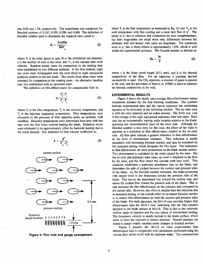
diameter. The film cooling hole pattern is presented in Fig. 3, and
consists of five staggered rows of 1.0 mm diameter showerhead film
holes. The holes are angled at 30" to the surface in the spanwise
direction and are oriented toward the outer diameter. The holes are 3.5
mm long, resulting in a length-to-diameter ratio (L/d) of 3.5. The
pitch-to-diameter ratio in both the spanwise and streamwise directions
is 4.0. There are 17 holes in rows 1, 3, and 5, and 16 holes in rows
2 and 4. In order to establish a more periodic flow in the midspan
region of the blade, holes 11 through 17 in all rows were permanently
covered with smooth tape. Computations by Heidmann (1995) using
the viscous flow solver rvc3d (Chima and Yokota, 1990) were used to
place the holes such that the flow from the center row would evenly
split between the suction and pressure sides.
The test blade was instrumented with an array of 72 nickel thin-
film gauges. The gauges were manufactured by Tap Systems, Inc., and
consist of serpentine nickel sensing elements with copper leads. To
allow spanwise resolution of the temperature profile behind the film
cooling hole pattern, eight gauges were placed near midspan at each of
nine streamwise locations, five on the suction side and four on the
pressure side. These eight gauges were situated to completely span
one unit cell of the hole pattern as shown in Fig. 3. The streamwise
length of each gauge is 1.0 mm. The first row on each surface is 8.0
mm downstream of the center row of film holes, and the subsequent
rows are spaced at 13.5 mm intervals. Pressure surface distances are
considered positive. The thin-film gauges were calibrated by the
Cortez III Service Corporation. The steady data recording system
reads the gauge signals once per second for twenty seconds and records
the average value of all data. The amplified AC component of the
gauge signals are recorded on the Masscomp data system at a
frequency necessary to record about 50 time steps per wake passing.
The signals are recorded for a period of about 1200 wake passings.
The unsteady data are then phase-averaged.
The experiment was conducted for blowing ratios of 0.5 and 1.0.
The definition of blowing ratio used to determine the required injectant
velocity is:
p vM - (1)
p V.
where c indicates injectant conditions and _ indicates freestream
conditions. The ratio of injectant to freestream density for air and CO s
was0.90and1.38,respectively.TheexperimentwasconductedforStrouhalnumbersof0.167,0.250,0.500,and0.600.ThedefinitionofStrouhalnumberusedtodeterminetherequiredrotorspeedis:
2_NDnSt - (2)
60Vw
where N is the rotor speed in rpm, D is the cylindrical rod diameter,
n is the number of rods in the rotor, and V. is the cascade inlet axial
velocity. Baseline steady cases for comparison to the rotating data
were established by two different methods. In the first method, eight
test cases were investigated with the rotor fixed in eight equispaced
positions relative to the test blade. The results from these cases were
averaged for comparison to the rotating cases. An alternative baseline
case was established with no upstream rotor.
The definition of film effectiveness for compressible flow is:
T-Tf r
11-T-T
C r
(3)
where Tf is the film temperature, T r is the recovery temperature, and
T_ is the injectant stagnation temperature. Film temperatures were
measured in the presence of film injection under an adiabatic wall
condition. Recovery temperatures were determined from tests with thin
tape over the film holes without heating the blade. Radiation errors
were estimated to be approximately offset by backside heating due to
the warm plenum. The definition of heat transfer coefficient is:
q tt
h- (4)T-T
w y
suction surface
pressure surface
Spanwisegauge location: 1 2 345 678
__ 1.0mm
T8.0 mm
1Figure 3: Film hole and gauge arrangement.
where Tf is the film temperature as measured in Eq. (3) and T. is the
wall temperature with film cooling and a local heat flux of q". The
errors in q" due to radiation and conduction are now complementary,
but their magnitudes are small since only differences between the
adiabatic wall and heated wall cases are important. The maximum
error in q" due to these effects is approximately 1.0%, which is well
within the experimental accuracy. The Nusselt number is defined as:
hcNu - (5)
k
where c is the blade chord length (63.5 mm), and k is the thermal
conductivity of the film. For air injection, a constant thermal
conductivity is used. For CO 2 injection, a mixture of gases is present
at the wall, and the procedure of Bird et al. (1960) is used to estimate
the thermal conductivity at the wall.
EXPERIMENTAL RESULTS
Figure 4 shows the steady span-average film-effectiveness versus
streamwise distance for the four blowing conditions. The symbols
indicate experimental data and the curves represent the correlating
equation to be discussed in the following section. The no rotor case
is with the rotor removed and no wakes present. The St--0, ave. case
is the average of the eight equispaced stationary rotor test cases. Each
case has an incrementally varying wake location relative to the blade,
spanning one circumferential pitch of the rotor rods. Although theStrouhal number is thus zero for this case, the effect of the wake is
apparent as a reduction in film effectiveness relative to the no rotor
case. All four plots indicate a general reduction in film effectiveness
as the level of unsteadiness increases. This reduction is nearly
monotonic with increasing Strouhal number, and may be explained by
the increased mixing which dissipates the film layer. The reductions
in film effectiveness are most pronounced on the blade suction surface.
This phenomenon is explained by the swirl caused by the rotor. For
the no rotor and stationary rotor cases, no swirl is imparted to the flow
by the rotor, and the flow enters the cascade with zero swirl. This
condition establishes a particular attachment line on the blade, and
determines the split of coolant between the suction and pressure sides
of the blade. As the Strouhal number increases, the wake-producing
rods impart swirl to the freestream toward the pressure side of theblade. This moves the attachment line toward the suction side, and
skews the coolant flow toward the pressure side of the blade. This in
turn increases the film effectiveness on the pressure side compared to
the suction side. However, this effect is smaller than the reduction due
to increased mixing, so the overall effect of increased Strouhal number
is to reduce film effectiveness on both the suction and pressure sides
of the blade. For both injectants, the M=I.0 case provides higher film
effectiveness than the M--0.5 case, indicating that the film remains
attached to the blade surface at M=I.0. This is due to the relatively
shallow angle of injection and the very nature of showerhead cooling.
The freestream velocity is nearly normal to the blade surface, which
tends to force the injectant to remain attached. Nusselt numbers are
found to remain nearly constant under changes in Stouhal number.
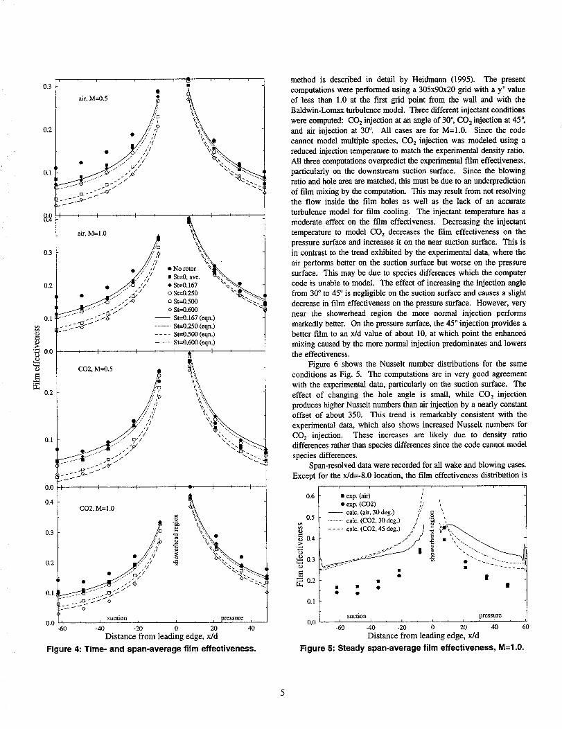
Figure 5 presents the M=l.0 no rotor experimental film
effectiveness data in comparison with calculations performed using the
viscous flow solver rvc3d with no upstream wake. The computational
0.3
0.2
0.1
8:_
0.3
0.2
0.1
_D
"_ 0.0
0.2
0.1
0.0
0.4
0.3
0.2
0.1
, 8= ,
. \air, M=0.5 _ ,_
//7
• "__"...
,,4....:// _i_i "
• .."S..."" // _.. .......
e_ ."'3"" _"-_"
t I ' I '
air, M=I.0
.:..'Q
:: i]
.;f/
I t I , I
CO2, M=0.5 j
//,,/m/_., -/ //
.'/jl
..'/ S I,.," _/
I / _ 1 , I
_ '..,,
• No rotor '_• St=0, ave. '_ _'-.._..i St=0.167 _'_
oSt--0.500 "_ -.....
o St=0.600 "'_
-- St=0.167 (eqn.)
C02, M=I.O
/
suction
............St=0.250 (eqn.)
.... St=0.500 (eqn.)-- -- - St=0.600 (eqn.)
I i' I _ I
"_..
!
I o_ I , I [/
k_ _,_
\x ",.
, , i i , , i pressure i0.0 -60 -40 -20 0 20 40
Distance from leading edge, rdd
Figure 4: Time- and span-average film effectiveness.
method is described in detail by Heidmann (1995). The present
computations were performed using a 305x90x20 grid with a y* value
of less than 1.0 at the first grid point from the wall and with the
Baldwin-Lomax turbulence model. Three different injectant conditions
were computed: CO2 injection at an angle of 30'; CO_ injection at 45 °,
and air injection at 30 °. All cases are for M=I.0. Since the code
cannot model multiple species, CO2 injection was modeled using a
reduced injection temperature to match the experimental density ratio.
All three computations overpredict the experimental film effectiveness,
particularly on the downstream suction surface. Since the blowing
ratio and hole area are matched, this must be due to an underprediction
of film mixing by the computation. This may result from not resolving
the flow inside the film holes as well as the lack of an accurate
turbulence model for film cooling. The injectant temperature has a
moderate effect on the film effectiveness. Decreasing the injectant
temperature to model CO z decreases the film effectiveness on the
pressure surface and increases it on the near suction surface. This is
in contrast to the trend exhibited by the experimental data, where the
air performs better on the suction surface but worse on the pressure
surface. This may be due to species differences which the computer
code is unable to model. The effect of increasing the injection angle
from 30<' to 45" is negligible on the suction surface and causes a slight
decrease in film effectiveness on the pressure surface. However, very
near the showerhead region the more normal injection performs
markedly better. On the pressure surface, the 45 ° injection provides a
better film to an x/d value of about 10, at which point the enhanced
mixing caused by the more normal injection predominates and lowersthe effectiveness.
Figure 6 shows the Nusselt number distributions for the same
conditions as Fig. 5. The computations are in very good agreement
with the experimental data, particularly on the suction surface. The
effect of changing the hole angle is small, while CO2 injection
produces higher Nusselt numbers than air injection by a nearly constant
offset of about 350. This trend is remarkably consistent with the
experimental data, which also shows increased Nusselt numbers for
CO2 injection. These increases are likely due to density ratiodifferences rather than species differences since the code cannot model
species differences.
Span-resolved data were recorded for all wake and blowing cases.
Except for the x/d=-8.0 location, the film effectiveness distribution is
0.6 • exp. (air) /• exp. (co2) ,'.., ',
L - calc. (air, 30 deg.) +f/ _ _,0.5 / ............talc. (CO2, 30 deg.) I "_ . ,
L .... talc. ,C02,45 deg.).> 77/ _ ,..__0.3 ..... 272222;
• |0.2 -
0.1
0.0 'suction pressure
, ii , i i i i
-60 -40 -20 0 20 40 60
Distance from leading edge, x/d
Figure 5: Steady span-average film effectiveness, M=I.0.

nearly uniform. At x/d=-8.0 (Fig. 7), a large spanwise variation in film
effectiveness is found. Spanwise gauge location 1 is repeated as
location 9 to complete one spanwise unit cell. Data points are only
shown for working gauges. The trends are consistent for all Strouhal
number cases. The largest spanwise variations occur when the rotor
is removed, due to the absence of wake-induced mixing of the film.
As the Strouhal number is increased, not only does the span-average
film effectiveness decrease, but the spanwise variations decrease as
well, indicating that the higher wake passing speeds provide more
spanwise mixing of the film. Spanwise locations 2 and 3 comprise the
lowest film effectiveness region, and thus correspond to the gap
between two adjacent film jets. It appears that the presence of a rotor
wake actually increases the film effectiveness slightly in this region.
This increase offsets the decrease in the high film effectiveness region
(spanwise locations 5 through 8), so the span-average film
effectiveness is not degraded by the presence of a rotor wake or by
increasing Strouhal number up to about St=0.250. This helps explain
the behavior seen in on the suction side in Fig. 4, where the presence
of a rotor has a greater effect at larger distances from the film holes.
Near the film holes, the wake acts to effectively spread the film jet,
reducing spanwise gradients but not the span-average film effectiveness
since the gaps between the film jets are filled. Farther downstream,
the effect of this spanwise mixing of the jet begins to reduce the span-
6000
4000
20o0
• exp. (air)• exp. (carbondioxide)
-- calc. (air, 30 deg.)........... calc. (CO2, 30 deg.).... calc. (CO2, 45 deg.)
Z
,///
• 0 ..._-_ _"
o
suction , , _ , _ , _ pressure _ ,
0 -60 -40 -20 0 20 40 60
Distance from leading edge, rdd
Figure 6: Steady span-average Nusselt number, M=I.0.
No rotor
St--O, average value
t ........ • St=0.167
*- - - • St--0.250
"- -- • St--0.500
- --* St---0.600
0.0 t _ _ r r T ,2 3 4 5 6 7 8
Spanwise gauge location
Figure 7: Local film effectiveness, CO 2, M=I.0, x/d=-8.0.
0.3
;>
0.2
L_0.1
average film effectiveness since the low film effectiveness gaps are
already filled, and no additional benefit results from spanwise mixing.
Nusselt number results indicate very little spanwise variation, even near
the leading edge.
The gauges showed some time variations of film effectiveness, but
these were random and lacked repeatability. The attempts to extract
meaningful unsteady results are documented in detail by Heidmann
(1996). Conduction effects in the substrate were the primary cause of
this problem. Because of these difficulties, it was decided to scrutinize
the results from the stationary wake data that was obtained as a
limiting case of zero Strouhal number. Figure 8 shows the span-
average steady film effectiveness variations with rotor wake location
for the suction and pressure surfaces of the blade. Wake location 5 is
for the wake aligned with the blade leading edge. Wake location 1 is
the same as location 9, and is for the wake at mid-passage. These
plots represent the limiting case of the rotating tests at zero rotational
speed.
The suction surface results show a highly repeatable distribution
for all streamwise locations. With the wake impinging on the blade
(wake location 5), the film effectiveness is reduced by about 0.05 at
x/d=-8.0 and almost 0.10 at the downstream locations. This result is
expected due to the enhanced film mixing caused by the increased
turbulence in the wake. It is surprising that the absolute reductions in
film effectiveness are greater at the downstream locations, because the
levels of film effectiveness are lower at these locations. However, this
supports the explanation given for the behavior in Fig. 7. The
impingement of the wake on the leading edge increases spanwise
o.3suction surface
................ • ................. a ,o................. • ................
0.2 - ".....
• "- " .- _,f _ x/d=-8.00.1 \ "s.. "o
"_ -..,.. ..... ._" _-I- t, ........ * x/d=-21.5
_ :l:-- ---.-------_- ' •- - - • x/d=-35.0o •- -- • x/d=-48.5
o _ - --4 rdd=-62.0
,_-,_ pressure surface
0.3....... .o................
............... _ ................. Q. . Iv .........
0.2 ' ..."" ,e----- ---
\ - -_ / _ x/d= 8.0
0.1 \\ _,-" _ * ........ • x/d=21.5N_ _ _" - - • x/d=35.0
-- • rdd--48.5
suction side wake l.e. pressure side wakeI I I 5 I I I
0.0 2 3 4 5 6 7 8 9
Rotor wake location
Figure 8: Span-average film effectiveness, CO2, M=I.0, St=0.
6

mixing of the film, but this action is actually favorable in the low
effectiveness gaps between jets, which at rdd=-8.0 partially offsets the
detrimental dissipation of the film. The pressure surface results
indicate an even greater reduction in film effectiveness due to wake
impingement than on the suction surface. Reductions of about 0.15 at
x/d=8.0 and at least 0.10 downstream are noted. Both the suction and
pressure surface data show an asymmetry of the film effectiveness
profile. For both sides of the blade, the film effectiveness is reduced
more for a wake location nearer that side, as expected. Thus the
suction surface film effectiveness is reduced more at wake locations 3
and 4 than at wake locations 6 and 7, while the opposite is true on the
pressure surface. The only streamwise location which indicates an
effect of wake location on Nusselt number is at x/d=8.0, which is the
pressure surface leading edge. The wake exhibits a velocity defect
which decreases the Nusselt number by about 20 percent because of
lower velocity gradients at the wail.
WAKE-AFFECTED FILM COOLING MODEL
Analytical film effectiveness correlations for slot injection are
given by Goldstein (1971), and are typically of the form:
C1
_= (6)_. X C
1.0+
where C 1, C 2, and C 3 are constants, x is the streamwise distance from
the slot, M is the blowing ratio, and S is the slot width. For film
cooling on a blade with discrete holes, an analytical description of the
boundary layer is usually not available. For this case, empirical
correlations are often used, although their applicability is limited to the
geometry and conditions from which they were derived. Using the
basic form given for slot injection, others have produced correlations
of experimental data. For example, Takeishi et ai. (1990) have given
an empirical correlation for film effectiveness on a low aspect ratio
turbine nozzle with suction and pressure side circular hole film cooling.
S now becomes the effective slot width, or the width of a slot having
the same flow area as the hole pattern. For n rows of circular holes,
S=n=d2/4p, where p is the hole spanwise pitch.
The form of the correlation which proved to provide the best
agreement with the experimental data for the present experiment is:
C1
= -cst (7)Cx ±c 72 c
1.0 + ('MS(1.0:1: _M :t:CSt) )
Positive signs are taken for the pressure surface and negative for the
suction surface. S is taken to be half of the effective slot width for all
rows of holes. The form of Eq. (7) follows that of Eq. (6), but
supplements it with additional terms to account specifically for
suction/pressure surface and Strouhal number differences.
The primary effect of the wake unsteadiness on the film
effectiveness is to reduce it as the rotational speed or Strouhal number
increases. This is evident in Fig. 4. In addition, the change in film
effectiveness for a given change in Strouhal number is fairly constant
with downstream distance x on either the suction or pressure surface.
The -CTSt term is used to model this effect. This term provides
excellent agreement over the range of experimental data. In addition,
the simplicity of this term allows for ease of interpretation. C7 is the
slope of the film effectiveness versus Strouhal number trend.
The Strouhai number effect, although nearly constant with x,
differs on the suction and pressure surfaces due to the shifting of the
attachment line. This phenomena is addressed in the correlation
through the C4St term. This term arises from an assumption that the
changes in injectant split are linear with Strouhai number. The
quantity MS is an effective flow rate and is modified in the correlation
to be MS(1.0-_3M+-C4St). This modification maintains the total flow
rate on both sides of the blade at 2MS.
The term C3M arises from the observation that the difference
between the pressure and suction surface film effectiveness is greater
for M=I.0 than for M=0.5 for both air and CO2 injection. The
physical interpretation of the C3M term is that the injectant split
depends upon the blowing ratio. At low blowing ratios, the momentum
of the injectant is low, and the split between pressure and suction
surfaces depends primarily on the geometric location of the film holes.
At high blowing ratios, the injectant penetrates more deeply into the
freestream, and the split may be influenced by the angle of injection
and freestream flow behavior. For the present experiment, the pressure
surface is favored for higher blowing ratios, but this may be due to
geometric considerations unique to this configuration.
The C6 term represents the fact that the film effectiveness was
found to decay more rapidly in the streamwise direction on the
pressure surface than on the suction surface. This finding agrees with
the analysis of Ito et ai. (1978), which predicts better film cooling
performance on a convex wall than on a concave wail for streamwise
momentum flux ratios less than 1.0. For the showerhead cooling of the
present experiment, the injectant exits the hole with zero streamwise
momentum, resulting in a streamwise momentum ratio of zero for all
cases. Thus the convex (suction) surface should perform better than
the concave (pressure) surface to the same degree for all blowing
cases. The experimental data agrees with this prediction. Additionally,
the analysis of Ito et al. (1978) pertains to the performance of a fluid
element once it has established a trajectory on either side of the blade.
Because of this the C 6 term should be independent of blowing ratio for
showerhead cooling, and is incorporated as such in the exponent.
The application of a least-squares algorithm on the experimental
data produced the coefficients for Eq. (7) shown in Table 1.
Table 1:
The root mean
air
C I 0.761
C 7 0.054
C3 0.139
C 4 0.286
C_ 0.792
C a 0.033
C7 0.093
square average of
Correlation Coefficients for Equation 7.
CO 7
0.948
0.094
0.241
0.144
0.762
0.014
0.095
the error in film effectiveness using

thesecoefficientsisabout0.0068 for air and 0.0074 for CO2.
In terms of their effect on the film effectiveness, Cs and C7 remain
fairly constant between injectants. In particular, the magnitude of the
Strouhal number effect (C7) is almost the same for both injectants,
having an average value near 0.094 for both air and COt This may
indicate a relative insensitivity of wake passing effects to injectant
density ratio. The agreement between C 5 for air and CO 2indicates that
the film effectiveness decay rate is similar for both cases. The fact
that the values are below 1.0 implies a more gradual decay of film
effectiveness with downstream distance than for the cases of Takeishi
et al. (1990), which gave values of 1.0 and 1.6 for a non-showerhead
film cooled blade. This is to be expected for showerhead cooling,
since the injectant has less opportunity to separate from the blade than
does suction and pressure surface injection. C 3, C4, and C6 are the
three coefficients associated with differences between suction and
pressure surface film effectiveness values. All of these coefficients
have the same sign for air and CO 2, which indicates that the trend
between suction and pressure surface data is consistent for the two
injectants. The magnitudes of these coefficients differ, however. It
should be noted that the specific heat of CO 2 is 14 percent lower than
that of air. As indicated by Mehendaie et al. (1994), this causes the
measured film effectiveness values for CO 2 to be conservative by up
to 14 percent, depending on the concentration of CO 2 at the wall.
However, due to the generally small concentrations, this error is
estimated to result in less than a 3 percent underprediction of the actual
value over most of the blade.
Figure 4 shows comparisons between the experimental data and
correlations for air at blowing ratios of 0.5 and 1.0 and CO2 at blowing
ratios of 0.5 and 1.0, respectively. It can be seen that the correlation
is in excellent agreement with the experimental data for air injection
at both blowing ratios. The change in film effectiveness with
increasing Strouhal number is captured quite well. This indicates that
the assumption of linear decay of film effectiveness with Strouhal
number is proper. In general, the correlation agrees well with the CO2
data. The magnitude of the Strouhai number effect is underpredicted
for a blowing ratio of 1.0, particularly on the suction surface, and is
overpredicted for a blowing ratio of 0.5, particularly on the pressuresurface. This indicates that the correlation might properly require a
blowing ratio influence on the CTSt term. However, in view of theexcellent correlation achieved with the relatively simple correlation,
equation, the recommended correlation stands.
Mehendaie et al. (1994) have presented film effectiveness values
for St=0.1 and 0.3. Their experiment was conducted for a more
highly-loaded turbine blade and consists of suction and pressure surface
cooling in addition to the showerhead cooling of the present study, so
direct comparisons are difficult. However, the Strouhal number effect
is nearly constant in the streamwise direction as in the present study.
The mean film effectiveness decrement predicted by the current modelfor a Stronhal number increase of 0.2 is 0.019. The Mehendale et al.
(1994) data set shows a decrement ranging from 0.025 at M=0.8 to
slightly negative (enhancement) at M=0.4 on the pressure surface, with
a mean value of about 0.013. The model predicts a smaller film
effectiveness decrement on the pressure surface due to attachment linevariations at higher Strouhal numbers. This effect is present,
particularly at M--0.4 and M=l.2, although it is smaller than in the
present study, presumably due to the presence of suction and pressure
surface (non-showerhead) cooling, which is unaffected by attachment
line variations.
CONCLUSIONS AND RECOMMENDATIONS
A model has been developed which accounts for the primary
effects of wake passing unsteadiness on film cooling effectiveness for
a showerhead-cooled stationary turbine blade. The experimental film
effectiveness as correlated by the model is seen to be reduced by wake
passing unsteadiness for all cases by a nominal value of 0.094.St. The
Strouhal number has a measurable effect on the flow split between the
suction and pressure surfaces for showerhead cooling. A higher
Strouhal number skews the coolant flow toward the pressure surface,
producing better cooling on the pressure surface and worse on the
suction surface. Nusselt numbers were found to remain fairly constant
with changing Stronhai number, but to be higher for CO2 than for air
injection.
The unsteady experimental data proved difficult to execute and
interpret. It is recommended that future experiments which aim to
measure high frequency temperature fluctuations use double-sided
gauges similar to those used by Abhari and Epstein (1992). Several
important mechanisms of wake passing were isolated by other methods.A clear and consistent reduction in film effectiveness was found for
stationary wake locations near the blade leading edge. Reductions of
up to 0.10 and 0.15 were exhibited on the suction and pressure
surfaces, respectively. Nusselt number reductions of about 20 percent
were found near the pressure side leading edge with the wake
impinging on the blade. Based on the success of these data, stationary
wake experiments are recommended in the absence of advanced
instrumentation capable of resolving high frequency data. In addition,
the averaging of these data more properly represent a limiting case for
wake passing experiments than the more traditional no wake condition.
Another unsteady mechanism identified by the steady experiments is
the spanwise variation in film effectiveness near the suction side
leading edge for various Strouhai numbers. The reduction in span-
average film effectiveness is found to be primarily due to reductions
near the peak film effectiveness value. This indicates that the wake
passing influences the film jets by enhancing their spanwise mixing.
Nusselt numbers are predicted quite well by the steady
computation. Film effectiveness prediction is not as successful. The
computation predicts higher film effectiveness values than the
experiments, which indicates an underprediction of film mixing. This
is thought to be primarily due to not resolving the flow inside the filmholes, as well as the absence of reliable turbulence models for film
cooling.
A better understanding of the complex interactions between
unsteady flOWS and film cooling flows is necessary to improve existingmodels arid achieve better film cooling designs It is hoped that the
results of this study represent a step in this direction, and will lead toother research in the field.
REFERENCES
Abhari, R. S. and Epstein, A. H., 1992, "An Experimental Study
of Film Cooling in a Rotating Transonic Turbine", ASME Paper
92-GT-201.
Bird, R. B., Stewart, W. E., and Lightfoot, E. N., 1960, Tr_soo_
Phenomena, John Wiley & Sons.
Chima, R. V. and Yokota, J. W., 1990, "Numerical Analysis of
Three-Dimensional Viscous Flows in Turbomachinery", AIAA J., Vol.

28,No.5,pp.798-806.Domey,D.J.,Davis,R.,andEdwards,D.,1992,"Investigation
ofHotStreakMigrationandFilmCoolingEffectsonHeatTransferinRotor/StatorInteractingFlows",N00140-88-C-0677- Report1,UTRCReport91-29.
Dring,R. P.,Blair,M. F., andJoslyn,H. D., 1980,"AnExperimentalInvestigationofFilmCoolingonaTurbineRotorBlade",JournalofEngineeringforPower,Vol.102,pp.81-87.
Funazaki,K.,Koyabu,E.,andYamawaki,S.,1996,"EffectofPeriodicWakePassingonFilmEffectivenessof InclinedDiscreteCoolingHolesAroundtheLeadingEdgeof aBluntBody",ASMEPaper96-GT-207.
Goldstein,R. J., 1971,"FilmCooling",Advancesin HeatTransfer,Vol.7,pp.321-379.
Heidmann,J.D.,1995,"ANumericalStudyoftheEffectofWakePassingonTurbineBladeFilmCooling",NASATM-107077andAIAA-95-3044.
Heidmann,J.D.,1996,"TheEffectofWakePassingonTurbineBladeFilmCooling",NASATM-107380andPh.D.Dissertation,CaseWesternReserveUniversity(1997).
Ito,S.,Goldstein,R.J.,andEckert,E.R.G.,1978,"FilmCoolingofaGasTurbineBlade",JournalofEngineeringforPower,Vol.100,pp.476-481.
Mehendale,A.B.,Han,J.-C.,Ou,S.,andLee,C.P.,1994_"UnsteadyWakeOveraLinearTurbineBladeCascadeWithAirandCO2FilmInjection:PartII - EffectonFilmEffectivenessandHeatTransferDistributions",JournalofTurbomachinery,Vol.116,pp.730-737.
O' Brien,J. E. andCapp,S.P., 1989,"Two-ComponentPhase-AveragedTurbulenceStatisticsDownstreamof a RotatingSpoked-WheelWakeGenerator",JournalofTurbomachinery,Vol.111,pp.475-482.
Ou,S.,Han,J.-C.,Mehendale,A.B.,andLee,C.P.,1994,"UnsteadyWakeOveraLinearTurbineBladeCascadeWithAir andCO2FilmInjection:PartI - EffectonHeatTransferCoefficients",JournalofTurbomachinery,Vol.116,pp.721-729.
Rigby,M.J.,Johnson,A.B.,andOldfield,M.L.G.,1990,"GasTurbineRotorBladeFilmCoolingWithandWithoutSimulatedNGVShockWavesandWakes",ASMEPaper90-GT-78.
Simoneau,R. J.,Morehouse,K. A.,VanFossen,G.J.,andBehning,F.P.,1984,"EffectofaRotorWakeonHeatTransferFromaCircularCylinder",NASATM-83613.
Takeishi,K.,Matsuura,M.,Aoki,S.,andSato,T.,1990,"AnExperimentalStudyofHeatTransferandFilmCoolingonLowAspectRatioTurbineNozzles",JournalofTurbomachinery,Vol.112,pp.477-487.
Takeishi,K.,Aoki,S.,Sato,T.,andTsukagoshi,K.,1992,"FilmCoolingonaGasTurbineRotorBlade",JournalofTurbomachinery,Vol.114,pp.828-834.

Form ApprovedREPORT DOCUMENTATION PAGE OMBNo. 0704-0188
Pub,,c reponiug burden Io¢ this co_leclion of Infoemaflon is eSti .r.r.r.r_ed.toavei:age I.h_.r p_. r.epporme,Inc_dlng _U__timej_or._r__;,__}c.._,,.u_--._.T_=_',_g ex.lst_ggd_Dec_rc_._
gathenng and maJmalnlng the data needed, ano completing ano re_ewm 0 the cotmcuon o; ,morrnaz,on. _ c__.mn_n_s, .eg_,L,g m_ uu_,_ ,-- =-_ _-_._P_f(_m _-co,ectio,of Info_. Ind.d,ugsuggestionsforreducingthisburden,to Weshlngto.Hea_.uane.mServlo_s.u_rec_omte_tOrdr_n_onmTm.o_l_r'_asa_o.e_D__)3 _,.Davis Highway, Suite 1204, Adlngton, VA 22202-4302, and to the Office of Management ano l_uoget, r,apem_om rmou_on r'folu_ _u*w_uloo I, w.=*.._j.m.
1. AGENCY USE ONLY (Leave blanlO 2. HI=PORTDATE 3. F_.PO_TTYPEANDDATE._COV_-HP-J_
March 1997 Technical Memorandum
4. TITLE AND SUBTITLE 5. FUNDING NUMB_J_
An Experimental Study of the Effect of Wake Passing on Turbine Blade
Film Cooling
6. AUTHOR(S)
James D. Hcidmann, Barbara L. Lucci, and Eli Rcshotko
7. PERFORMING ORGANIZATION NAME(S) AND ADDRESS(ES)
National Aeronautics and Space Administration
Lewis Research Center
Cleveland, Ohio 44135-3191
9. SPONSORINGJMONITORING AGENCY NAME(S) AND ADDRESS(ES)
National Aeronautics and Space Administration
Washington, DC 20546-0001
WU-505-62-10
8. PERFORMING ORGANIZATIONREPORT NUMBER
E-10671
10. SPONSORING/MONn'ORI NG
AGENCY REPORT NUMBER
NASA TM- 107425
11. SUPPLEMENTARY NOTES
Prepared for the 42nd Turbo Expo sponsored by the American Society of Mechanical Engineers, Orlando, Florida, June 2-
5, 1997. James D. Heidmann and Barbara L. Lucci, NASA Lewis Research Center; Eli Reshotko, Case Western Reserve
University, Cleveland, Ohio 44106. Responsible person, James D. Heidrnann, organization code 5820, (216) 433-3604.
12a. DISTRIBUTION/AVAILABILITY STATEMENT 12b. Dk_, HIBUTION CODE
Unclassified - Unlimited
Subject Category 07
Thi._ pub_t--_fion is available from the NASA Center for AeroSpace Information, (301) 621--0390.
13. ABSTRACT (Maximum 200 words)
The effect of wake passing on the showerhead film cooling performance of a turbine blade has been investigated experi-
mentally. The experiments were performed in an annular turbine cascade with an upstream rotating row of cylindrical
rods. Nickel thin-film gauges were used to determine local film effectiveness and Nusselt number values for various
injectants, blowing ratios, and Strouhal numbers. Results indicated a reduction in film effectiveness with increasing
Strouhal number, as well as the expected increase in film effectiveness with blowing ratio. An equation was developed to
correlate the span-average film effectiveness data. The primary effect of wake unsteadiness was found to be correlated by
a streamwise-constant decrement of 0.094-SL Steady computations were found to be in excellent agreement with experi-
mental Nusselt numbers, but to overpredict experimental film effectiveness values. This is likely due to the inability to
match actual hole exit velocity profiles and the absence of a credible turbulence model for film cooling.
14. SUBJECT TERMS
Turbines; Film cooling; Wakes
17. SECURITY CLASSIFICATION
OF REPORT
Unclassified
NSN 7540-01-280-5500
18. SECURITY CLASSIFICATION
OF THIS PAGE
Unclassified
19. SECURITY CLASSIFICATIONOF ABSTRACT
Unclassified
15. NUMBER OF PAGES
O916. PRICE CODE
A02
20. LIMITATION OF AB,_F.',ACT
Standard Form 298 (Rev. 2-8g)
Prescnloed by ANSI Std. Z39-18298-102