an experimental study of laminar flow for graphene
TRANSCRIPT

An Experimental Study of Laminar Flow for Graphene
Nanofluid in Double Micro Heat Exchanger
Mahmoud Abdallah
Mechanical Engineering Dept.,
Faculty of Energy Engineering
Aswan University
Aswan, Egypt
Mohamed Salem
Mechanical Engineering Dept.,
Faculty of Energy Engineering
Aswan University
Aswan, Egypt
M. Shaban Eissa
Mechanical Engineering Dept.,
Faculty of Energy Engineering
Aswan University
Aswan, Egypt
W. A. Aissa*
Mechanical Engineering Dept.,
Faculty of Energy Engineering
Aswan University
Aswan, Egypt
Abstract—In this paper, an experimental study was conducted on
double micro –heat exchanger device for laminar heat transfer of the
Graphene Nano platelets. The heat transfer, pressure drop and
pumping power of Graphene Nano fluid were measured. First, the
Nano fluid was prepared and the stability of the Nano fluid was
measured, then the thermal properties (viscosity, density, and
thermal conductivity) were measured experimentally in the
laboratory at different concentrations (0.02, 0.055 and 0.06% wt.). In
addition, the effect of weight fraction, inlet temperature and mass
flow rate on logarithmic mean temperature difference and the overall
heat transfer coefficient were evaluated in double micro–heat
exchanger device. The final results showed that the overall heat
transfer coefficient and effectiveness of double micro –heat exchanger
device improved by raising the weight fraction of Graphene Nano
platelets and the overall heat transfer coefficient improved to 51.1%
at Reynolds number of 425 and weight concentration of 0.06% wt.
The experimental results showed that pressure drop and pumping
power were higher for (0.06% wt.) compared to (0.02%wt. and
0.055% wt.).
Keywords—Nanofluid, Graphene, Double micro–heat
exchanger.
1. INTRODUCTION
Transport of energy is playing vital role in different applications
such as electrical energy, oil, gas and nuclear energy. Many of
applications use traditional heat transfer fluids such as distilled
Water, pumping oil, ethylene glycol (EG) and glycerol.
Enhancing the thermal conductivity of fluids becomes needful
for performance systems of energy [1,2]. References [3-7] stated
that Nano fluids refer to the nanoparticle mixing with liquid to
upgrade the thermo physical properties such as thermal
conductivity resulting in good stability and enhancement of heat
transfer coefficients and increment in the pressure drop and
pumping power. A lot of papers investigate experiments
conducted to upgrade the properties of thermo fluids by adding
Nano scale particles to liquids. Experimental studies for heat
transfer coefficient for Nano fluids across tubes as different
types [8-10] showed that many types of Nano scale particles
include oxides, diamond, metals and carbon Nano particles.
Experiments have been done on TiO2, CuO, Al2O3, and SiO2
Nano fluids [11, 12] to investigate the effect of the weight
fraction of nanoparticles on the thermal properties of fluids and
heat transfer coefficients. It was noticed that the range of
increment in the convective heat transfer coefficients under
turbulent and laminar flow conditions varied from 26% to 35%
[13, 14].
It was deduced that the effect of Nano fluid focusing on the heat
transfer coefficient is important in the turbulent regime versus
the laminar regime [15, 16].
Duangthongsuk. and Wongwises [17] and Khedkar et al. [18]
prepared TiO2 (21 nm) Nano fluid and used water as base fluid for
various concentrations (0.2–2% wt.) in horizontal double tube-
based heat exchanger as counter flow in turbulent region and
studied the convective heat transfer and pressure drop of Nano
fluid.
Newly, various researches were conducted to study improving
the performance of heat transfer by enhancing the thermal
conductivity of base fluid. Carbonic materials have low density
and high thermal conductivity compared with other metals and
metal oxides. Number of researches studied carbon Nano-based
nanostructures, including carbon nanotubes, carbon Nano fibers,
carbon black structures, graphene oxide (GO), graphene Nano
sheets and graphite flakes [19-24]
Novoselov et al. [25] are the first researchers who explored
graphene. Graphene is a 2D carbon material arranged as
monolayer material; its physical properties are high thermal
conductivities and low densities. Balandin et al. [26] and Baby and
Ramaprabhu [27] indicated that thermal conductivity of graphene
can be as high as 3kW/mK in axial and 5.2 kW/mK in-plane.
International Journal of Applied Energy Systems, Vol. 3, No. 2, July 2021
ISSN: 2636 - 3712 (Printed Version) ISSN: 2636 - 3720 (Online Version) 25

Ebrahimnia-Bajestan et al. [28] studied the convective heat
transfer of Nano fluids. No complete papers in this area explain
the various effective parameters. There were some researches
which show that the improvement in heat transfer coefficient due
to Nano fluids are associated with a number of undesirable
effects and calculated the pressure drop and pumping power
required to achieve the best of Nano fluid to be used in the
applications of heat transfer.
In this study, the laminar counter flow of graphene/distilled
water Nano fluid in Double Micro Heat Exchanger (DMHE) is
investigated experimentally. Nano fluids are prepared from
graphene and water at different weight concentrations (0.02,
0.055 and 0.06% wt.) The thermo physical properties were
measured at different temperatures and concentrations, and then
used the micro heat exchanger to calculate the heat transfer
characteristics of Nano fluids for Reynolds numbers varying
from 125 to 425. The influence of weight concentration on
pressure drops, pumping power, and heat transfer coefficient
under various Reynolds numbers are investigated. A flow chart
is utilized to have a better understanding of the sequence of the
current investigation is shown in Fig 1.
Fig.1 Flow chart of the current study progress
Abbreviations
DMHE Double Micro Heat Exchanger
GNP Graphene Nano platelet
SDBS Sodium Dodecyl Benzene Sulfonate
Nomenclatures
A Heat transfer area (m2 (
C Thermal capacity (-)
C𝑝 Specific heat capacity (J/kg. K)
Di
d
Inner diameter of inner tube for DMHE (m (
Inner diameter of pipe (m)
ƒ Darcy friction factor (-)
h Convective heat transfer coefficient(W/m2.K)
K Thermal conductivity (W/m.K)
L Length of pipe (m (
LMTD Logarithmic Mean Temperature Difference (K)
NTU Number of transfer units (-)
�̇� mass flow rate (Kg/s(
Nu Nusselt number (-)
P Pumping power (W)
∆𝑃 Pressure drop (KPa (
Q Heat transfer rate (J/s)
𝑅𝑒 Reynolds number (-)
T Temperature (K)
t Time (s)
U The overall heat transfer coefficient(W/m2.K)
V Nano fluid velocity (m/s(
Greek symbols
µ Absolute viscosity (m Pa.s)
𝜀 Effectiveness of DMHE (-)
𝜌 Density (kg/m3)
𝜑 Volumetric flow rate (m3/s)
∅ Weight fraction (-)
Subscripts
F Base fluid
In Inlet
nf Nano fluid
out Outlet
p Particle
w Water
2- Nano fluid preparation and measurements of stability
References [29 − 34] used two steps technique for
preparation of Nano fluid because it is economic and wide
range. Similarly, in this work, two steps technique was used. The
specifications of the GNPs are listed in table 1.
Nanoparticles (GNPs) were added to base fluid (distilled
water) with the surfactant Sodium Dodecyl benzenesulfonate
(SDBS) to reduce the aggregation due to London-van der Waals
reaction according to the literature survey[34]. GNPs were
mixed with water by using ultrasonic homogenize (VCX-500
Ultrasonic Processor 500 Watts, 60 amplitude) for one hour.
Five weight concentrations (0.02, 0.03, 0.04, 0.055 and 0.06 %
wt.) were prepared and mixed with distilled water. If high
concentrations of Nano fluids is used ( 0.06% wt.); the
viscosity increases and it becomes difficult for the Nano fluids
Nanofluid preparation
Measurement of thermo physical properties
(ρ, μ, Cp, K)
Experimentation (DMHE )
Determination of measured quantities
(�̇�, 𝑇𝑛𝑓,𝑖 , 𝑇𝑛𝑓,𝑜 )
�̇� �̇�
Calculation of heat transfer rate (Q)
Calculation of (LMTD, U, hnf, Re, ε)
Calculation of pumping properties
(∆𝑝, 𝜑)
Calculation of the pumping
power and friction factor (P, ƒ)
Faculty of Energy Engineering - Aswan University - Aswan - Egypt
26

to pass through the micro heat exchanger. Low concentrations
of Nano fluids ( 0.02% wt.) are utilized in previous studies
[34], Fig .2 shows the stability of Nano fluid after 90 days, and
additional techniques used to find out the stability of Nano fluid
called Zeta potential which gave good result for stability of
Nano fluid for 0.06% wt. in Fig .3.
Table 1. Properties of GNPs
Specification Property
Black granules Appearance
> 99.5% wt. Carbon content
300 m2/g Surface area
5-10 nm Thickness
5µm Width
0.03-.1 g/cc Bulk density
3000 W/mK Thermal conductivity (parallel to surface)
6 W/m K Thermal conductivity (perpendicular to surface)
Fig. 2 Nano fluid after 90 days
Fig. 3 Zeta potential distribution of (0.06% wt.) GNPs at water
3-Thermophysical properties of Nano fluids
3.1 Viscosity
The graphene Nano fluids viscosity at different
concentrations was measured using Ostwald U-Tube
Viscometer [35].
Fig.4 shows the measured Nano fluid viscosity for various
concentrations at different temperatures in the current study.
The viscosity of Nano fluids increased exponentially as a
function of nanoparticles concentration and the viscosity
decreased with increasing the temperature. Moreover, with the
increase in temperature, the nanoparticles become more active
and produce large distance between the nanoparticles and this is
due to weak adhesion forces in Nano fluid.
Batchelor proposed an expression for determining the
dynamic viscosity for rigid and spherical particles [36]. In the
model neglecting interactions between the particles, the
expression is as follows:
𝜇𝑛𝑓 = 𝜇𝑓(1 + 2.5∅ + 6.2∅2) (1)
where 𝜇𝑛𝑓 is absolute viscosity of Nano fluid (m Pa.s), 𝜇𝑓 is
absolute viscosity of base fluid (m Pa.s) and ∅ is weight
concentration of nanoparticles (-).
Fig. 5 shows the measured viscosity of the Nano fluid at
different concentrations at the room temperature (25°C)
compared to the Bachelor model. The results showed that the
viscosity of all Nano fluids increased exponentially as a function
of the concentration of nanoparticles. Given the relationship
between the shear stress and shear rate, it indicates that the GNP
Nano fluids behave as non-Newtonian fluids and that the shear
stresses of Nano fluids are higher than that of base fluids of all
concentrations so the concentration increased when shear stress
increased. Another reason for the measured viscosity is higher
because the accumulation of nanoparticles in the Nano fluid is
higher than that in the ideal suspension (Bachelor model), and
these results are similar to many previous studies [37 − 38].
3.2- Density
Density is an effective thermo physical property to be
studied, as the effect of density is to increase the pumping power
and the mass flowrate in the case of high density nanofluids.
Density of water and graphene-based nanofluids were measured
using a Portable digital density meter (DMA 35, Anton Paar
CO., and USA) [39] that shown in Fig 6. The results illustrated
in Fig. 7 show that the nanofluid density increased when the
concentration of nanoparticle was increased. The density
decreases as the temperature raises. The values of the nanofluids
densities which increased with increasing nano material
concentration are shown in Fig. 8.
The equation used to calculate the nanofluid density introduced
by Pak and Cho [38] as follows:
𝜌𝑛𝑓 = (1 − ∅)𝜌𝑓 + ∅𝜌𝑝 (2)
International Journal of Applied Energy Systems, Vol. 3, No. 2, July 2021
27

where 𝜌𝑛𝑓 is density of nanofluid (kg/m3), 𝜌𝑓 is the density of
base fluid (kg/m3) and ∅ is weight concentration of nanoparticles
(-).
3.3 Thermal conductivity
Thermal conductivity is playing vital role for improving the
convective heat transfer coefficient. In this study the thermal
conductivity of nanofluid was calculated with equations (3-5)
were considered precise equations for calculating the thermal
conductivity of solid and liquid mixtures containing spherical
particles. The results in Fig.9 indicate increase in thermal
conductivity upon increasing particle concentration. The
thermal conductivity increases with Brownian motion, which
occurs as interaction between nanoparticles and molecules of
basic fluids and causes smaller nanoparticles to raise their
surfaces and increase the number of interactions between them,
which lead to increase in thermal conductivity.
𝑘𝑛𝑓
𝑘𝑓
=𝑘𝑝 + 2𝑘𝑓 − 2∅(𝑘𝑓 − 𝑘𝑝)
𝑘𝑝 + 2𝑘𝑓 + ∅(𝑘𝑓 − 𝑘𝑝) (𝑀𝑎𝑥𝑤𝑒𝑙𝑙) [40] (3)
𝑘𝑛𝑓 = 𝑘𝑓(4.97∅2 + 2.72∅ + 1) (𝐻𝑎𝑚𝑖𝑙𝑡𝑜𝑛) [41] (4)
𝑘𝑛𝑓 = 𝑘𝑓(1 + 3∅ + 4.51∅2) (𝐿𝑢 𝑎𝑛𝑑 𝐿𝑖𝑛) [42] (5)
where knf , kf and kp are thermal conductivity of nanofluid, base
fluid and nanoparticle respectively (W/m.K) and they are
dimensionless and ∅ is weight concentration of nanoparticles
(-).
Fig. 4 The GNP nanofluids viscosity at different temperatures.
Fig. 5 Comparison between the viscosity of Nano fluid GNP in the current
study and the theoretical model at 25℃
Fig. 6 Portable digital density meter [39].
Fig.7 Density of the GNP Nano fluids at different temperatures.
Faculty of Energy Engineering - Aswan University - Aswan - Egypt
28
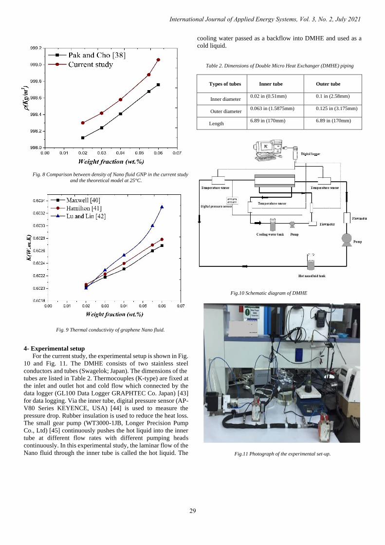
Fig. 8 Comparison between density of Nano fluid GNP in the current study
and the theoretical model at 25°C.
Fig. 9 Thermal conductivity of graphene Nano fluid.
4- Experimental setup
For the current study, the experimental setup is shown in Fig.
10 and Fig. 11. The DMHE consists of two stainless steel
conductors and tubes (Swagelok; Japan). The dimensions of the
tubes are listed in Table 2. Thermocouples (K-type) are fixed at
the inlet and outlet hot and cold flow which connected by the
data logger (GL100 Data Logger GRAPHTEC Co. Japan) [43]
for data logging. Via the inner tube, digital pressure sensor (AP-
V80 Series KEYENCE, USA) [44] is used to measure the
pressure drop. Rubber insulation is used to reduce the heat loss.
The small gear pump (WT3000-1JB, Longer Precision Pump
Co., Ltd) [45] continuously pushes the hot liquid into the inner
tube at different flow rates with different pumping heads
continuously. In this experimental study, the laminar flow of the
Nano fluid through the inner tube is called the hot liquid. The
cooling water passed as a backflow into DMHE and used as a
cold liquid.
Table 2. Dimensions of Double Micro Heat Exchanger (DMHE) piping
Outer tube Inner tube
Types of tubes
0.1 in (2.58mm)
0.02 in (0.51mm)
Inner diameter
0.125 in (3.175mm)
0.063 in (1.5875mm)
Outer diameter
6.89 in (170mm)
6.89 in (170mm)
Length
Fig.10 Schematic diagram of DMHE
Fig.11 Photograph of the experimental set-up.
International Journal of Applied Energy Systems, Vol. 3, No. 2, July 2021
29

4.1 Data Processing
The performance of heat exchanger can be assessed by
many variants; the overall heat transfer coefficient is one of
them. This variant describes the more heat transfer between
two fluids. The overall heat transfer coefficient and the
variations of Logarithmic mean temperature difference
(LMTD) for graphene nanofluid in laminar flow at different
Reynolds numbers are calculated using equations from (6-15)
[46] as follows:
𝑄𝑛𝑓 = �̇�𝑛𝑓(ℎ𝑛𝑓,𝑖 − ℎ𝑛𝑓,𝑜) = �̇�𝑛𝑓𝐶𝑝𝑛𝑓(𝑇𝑛𝑓,𝑖 − 𝑇𝑛𝑓,𝑜)
(6)
Where Q, �̇� and h are heat transfer rate (J/s), mass flowrate
(kg/s) and convective heat transfer (W/m2K); respectively
𝑄𝑎𝑣𝑔 =𝑄ℎ+𝑄𝑐
2 (7)
where 𝑄𝑎𝑣𝑔is the average heat transfer rate (J/s)
𝑈 =Qavg
A∗LMTD (8)
where U, A and LMTD are the overall heat transfer coefficient
(W/m2K), heat transfer area (m2) and Logarithmic Mean
Temperature Difference (K) respectively
𝐴 = 𝜋𝐷𝐿 (9)
𝐿𝑀𝑇𝐷 =(𝑇𝑛𝑓,𝑖−𝑇𝑐,𝑜)−(𝑇𝑛𝑓,𝑜−𝑇𝑐,𝑖)
𝐿𝑛[(𝑇𝑛𝑓,𝑖−𝑇𝑐,𝑜)
(𝑇𝑛𝑓,𝑜−𝑇𝑐,𝑖)]
(10)
ℎ𝑛𝑓 =𝑄ℎ
𝐿𝑀𝑇𝐷 𝐴ℎ
(11)
𝑁𝑢 =ℎ𝑛𝑓∗𝐷𝑖
𝑘𝑛𝑓 (12)
where Di is the inner diameter of inner tube (m).
𝐶 =(�̇� ∗𝑐𝑝)ℎ
(�̇� ∗𝑐𝑝)𝑐 (13)
where, C is the thermal capacity ratio (-).
𝑁𝑇𝑈 =𝑈∗𝐴
( �̇� ∗𝑐𝑝)ℎ (14)
NTU is the number of transfer units (-).
𝜀 =1−𝑒𝑥𝑝[−𝑁𝑇𝑈(1−𝐶)]
1−𝐶∗𝑒𝑥𝑝[−𝑁𝑇𝑈(1−𝐶)] (15)
where, 𝜀 is the effectiveness of a heat exchanger (-)
5-RESULTS AND DISCUSSION:
5.1 Convective heat transfer of Nano fluid
The overall heat transfer (U) and LMTD for water and
graphene Nano fluid at different Reynolds number; Re values in
laminar flow are explained in Fig. 12 and Fig.13 respectively.
In Fig. 12, it may be noticed that LMTD values reduced by
adding GNPs to water, according to Eq. 6 an inverse ratio
between U and LMTD, when the overall heat transfers
coefficient reduces, the LMTD increase. In Fig. 13, the results
state that overall heat transfers coefficient increased with
increasing the Nano fluid concentration compared to the base
fluid at Re = 425, the overall heat transfers coefficient increased
by 51.1%, 47.3% and 37% for 0.06%wt, 0.055% wt. and 0.02%
wt. respectively. In these experiments, the nanomaterial
concentration is the most efficient variant responsible for
increasing the overall heat transfer coefficient. The
enhancements of convective heat transfer of Nano fluid result
from the suspended particles which increase the thermal
conductivity of the mixture and the chaotic movement of the
nanoparticles accelerates energy exchange process in the fluid.
Fig.14. illustrate the convective heat transfer improvements
at different Reynolds numbers in the laminar regime of water
and Nano fluids resulting from the addition of nanoparticles to
water. The results indicate that the increase in the heat transfer
coefficients compared to the base fluid were 22%, 15.56%, and
13.33% for 0.06% wt., 0.055% wt. and 0.02% wt. respectively
for GNP Nano fluid at Re = 425.
Fig. 12 LMTD of GNPs Nano fluids and water variation on different Reynolds
numbers.
Faculty of Energy Engineering - Aswan University - Aswan - Egypt
30
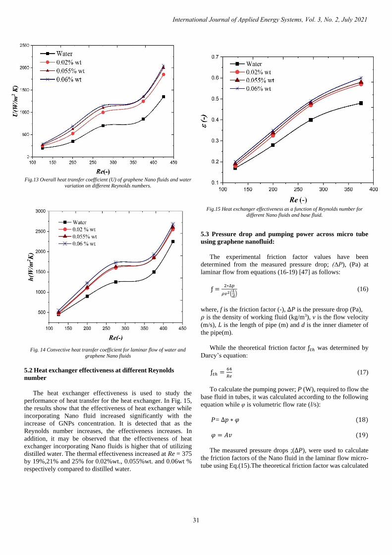
Fig.13 Overall heat transfer coefficient (U) of graphene Nano fluids and water
variation on different Reynolds numbers.
Fig. 14 Convective heat transfer coefficient for laminar flow of water and
graphene Nano fluids
5.2 Heat exchanger effectiveness at different Reynolds
number
The heat exchanger effectiveness is used to study the
performance of heat transfer for the heat exchanger. In Fig. 15,
the results show that the effectiveness of heat exchanger while
incorporating Nano fluid increased significantly with the
increase of GNPs concentration. It is detected that as the
Reynolds number increases, the effectiveness increases. In
addition, it may be observed that the effectiveness of heat
exchanger incorporating Nano fluids is higher that of utilizing
distilled water. The thermal effectiveness increased at Re = 375
by 19%,21% and 25% for 0.02%wt., 0.055%wt. and 0.06wt %
respectively compared to distilled water.
Fig.15 Heat exchanger effectiveness as a function of Reynolds number for
different Nano fluids and base fluid.
5.3 Pressure drop and pumping power across micro tube
using graphene nanofluid:
The experimental friction factor values have been
determined from the measured pressure drop; (∆P), (Pa) at
laminar flow from equations (16-19) [47] as follows:
ƒ =2∗∆𝑝
𝜌𝑣2(𝐿
𝑑) (16)
where, f is the friction factor (-), ∆𝑃 is the pressure drop (Pa),
𝜌 is the density of working fluid (kg/m3), v is the flow velocity
(m/s), 𝐿 is the length of pipe (m) and d is the inner diameter of
the pipe(m).
While the theoretical friction factor ƒ𝑡ℎ was determined by
Darcy’s equation:
ƒ𝑡ℎ =64
𝑅𝑒 (17)
To calculate the pumping power; P (W), required to flow the
base fluid in tubes, it was calculated according to the following
equation while φ is volumetric flow rate (l/s):
P= ∆𝑝 ∗ 𝜑 (18)
𝜑 = 𝐴𝑣 (19)
The measured pressure drops ;(∆P), were used to calculate
the friction factors of the Nano fluid in the laminar flow micro-
tube using Eq.(15).The theoretical friction factor was calculated
International Journal of Applied Energy Systems, Vol. 3, No. 2, July 2021
31

according to Eq. (16). Fig.16 illustrates comparison between the
actual and theoretical values of friction factor versus the
Reynolds number for water. The results shows that the
theoretical and actual values of friction factor are nearly close to
each other.
Fig.17 shows the variation of the friction factor of graphene
Nano fluids with Reynolds number. The results illustrate that the
Nano fluid with the higher concentration of 0.06 wt.% has the
highest friction factor. The increase in friction factor compared
to the base fluid for 0.06%wt is 45.65% at Re =100. The reason
for increasing the friction factor may be attributed to an increase
in the weight fraction, lead to an increase in the viscosity of the
fluid which reduces and resists the fluid flow.
As shown in Fig. 18, the pumping power; (P), enlarges with
the weight fraction of GNPs in the Nano fluid for all Reynolds
numbers. The results indicate that the pumping power increase
by 50%, 40% and 25% for 0.06% wt. ,0.055% wt. and 0.02%
wt. respectively compared to distilled water at Re =400. This
means that the Nano fluids increase the pumping power due to
the increase in nanoparticle concentration and also the increase
the GNPs friction factor lead to an increase in pumping power.
Fig.19 shows the effect of weight fraction of graphene Nano
fluid on pressure drop versus volume flow rate. The results show
that the pressure drop increases with increasing the Nano fluid
concentrations. The results showed that the pressure drop of
0.06% wt. compared to distilled water was 17.87% higher at
volumetric flow rate = 0.09 l/s and it is considered the highest
pressure drop. The variations in pressure drop may be attributed
to many causes, one of which is the concentration of the Nano
fluid that affects the thermos-physical properties and these
causes lead to change in the values of the pressure drop.
Fig.16 Comparison between measured and theoretical value of water
friction factors.
Fig. 20 shows the variation of heat transfer rate / pumping
power ratio (Q/P) with Reynolds number at different weight
concentrations. The results indicate that the Q/P value decreases
with the increase of concentration of Nano fluid, and increase
with the increase of Reynolds number to achieve the peak value
and then decreases. This may be attributed to that Q and P
increase with the increase of Reynolds number. However, the
rate of increase of Q till the peak value is higher than the rate of
increase of P and that the rate of increase of Q is lower than that
of increase of P for values of Reynolds numbers higher than that
corresponding to the peak value of Q/P ratio.
Fig.17 Nano fluid friction factor at different Reynolds number.
Fig. 18 Pumping power of Nano fluid GNPs concentrations versus
Reynolds number.
Faculty of Energy Engineering - Aswan University - Aswan - Egypt
32

Fig. 19 Effect of Weight fractions of GNPs at pressure drop versus volume
flow rate.
Fig. 20 Ratio of (Q/P) of Nano fluid GNPs concentrations versus Reynolds
number.
6- CONCLUSION
In the experimental study, laminar flow in DMHE with
various concentrations of Graphene Nano fluid (0.02, 0.055and
0.06% wt.) which was prepared using two steps technique and
the thermo physical properties were measured. In this study, it
was found that the weight fraction of GNPs had a remarkable
effect on the heat transfer coefficient, thermal effectiveness,
pressure drop and pumping power. The experimental results can
be concluded as follows:
1-The temperature has remarkable effect on density and
viscosity of graphene Nano fluid, when the density and viscosity
were increased with increasing temperature.
2-The thermal conductivity was enhanced for graphene Nano
fluid and the results indicate increase in the thermal conductivity
by increasing the concentration of the Nano fluid.
3-Enhancement of the convective heat transfer coefficient of
graphene Nano fluid at various concentrations (0.02, 0.055and
0.06% wt.) was compared with distilled water and the results
showed that the highest enhancement was achieved in the
0.06% wt. concentration.
4-The thermal effectiveness of Nano fluids (0.02, 0.055and
0.06% wt.) was higher than distilled water
5-Finally, the results showed that the friction factor of 0.02,
0.055and 0.06% wt. are higher than friction factor of distilled
water and the pumping power and pressure drop of Nano fluid
were higher than that of water.
References
[1] M. Mehrali, E. Sadeghinezhad, S.T. Latibari, S.N. Kazi, M. Mehrali,
M.N.B.M. Zubir and H.S.C. Metselaar, “Investigation of thermal conductivity
and rheological properties of Nano fluids containing graphene Nano platelets”, Nanoscale Res. Lett. 9 (1) (2014) 1–12
[2] M. Mehrali, S. Tahan Latibari, M. Mehrali, T.M.I. Mahlia, E. Sadeghinezhad
and H.S.C. Metselaar, “Preparation of nitrogen-doped graphene/palmitic acid shape stabilized composite phase change material with remarkable thermal
properties for thermal energy storage”, Appl. Energy 135 (2014) 339–349
[3] S.U.S. Choi, J. Eastman, “Enhancing thermal conductivity of fluids with nanoparticles”, Argonne National Lab., IL, United States, 1995, pp. 99–105.
[4] M. R. Safaei, H. Togun, K. Vafai, S. N. Kazi, and A. Badarudin,
“Investigation of heat transfer enhancement in a forward-facing contracting channel using FMWCNT nanofluids,” Number. Heat Transf. Part A Appl., vol.
66, no. 12, pp. 1321–1340, 2014, doi: 10.1080/10407782.2014.916101.
[5] M. Mehrali, S.T. Latibari, M. Mehrali and T.M. Indra Mahlia, H.S. Cornelis Metselaar, M.S. Naghavi, et al., “Preparation and characterization of
palmitic acid/graphene Nano platelets composite with remarkable thermal
conductivity as a novel shape-stabilized phase change material”, Appl Therm Eng 61 (2013) 633–640.
[6] M. Hassan, R. Sadri, G. Ahmadi and M. B. Dahari, “Numerical study of
entropy generation in a flowing nanofluid used in micro- and mini channels,”
Entropy, vol. 15, no. 1, pp. 144–155, 2013, doi: 10.3390/e15010144.
[7] M. Mehrali, S.T. Latibari, M. Mehrali, T.M. Indra Mahlia and H.S.
Cornelis Metselaar, “Preparation and properties of highly conductive palmitic acid/graphene oxide composites as thermal energy storage materials,” Energy
58 (2013) 628–634
[8] H. Yarmand, S. Gharehkhani, S.N. Kazi, E. Sadeghinezhad and M.R. Safaei, “Numerical investigation of heat transfer enhancement in a rectangular
heated pipe for turbulent Nano fluid,” Sci. World J. 2014 (2014) 9.
[9] M. Shanbedi, S.Z. Heris, M. Baniadam, A. Amiri and M. Maghrebi, “Investigation of heat-transfer characterization of EDA-MWCNT/DI-water
Nano fluid in a two-phase closed thermosiphon,” Ind. Eng. Chem. Res. 51 (3)
(2012) 1423–1428. [10] M. Memari, A. Golmakani and A.M. Dehkordi, “Mixed-convection flow
of nanofluids and regular fluids in vertical porous media with viscous heating,”
Ind. Eng. Chem. Res. 50 (15) (2011) 9403–9414. [11] W. Azmi, K. Sharma, P. Sarma, R. Mamat and S. Anuar, “Comparison of
convective heat transfer coefficient and friction factor of TiO2 nanofluid flow in
a tube with twisted tape inserts,” Int. J. Therm. Sci. 81 (2014) 84–93. [12] H. Togun, M.R. Safaei, R. Sadri, S.N. Kazi, A. Badarudin, K. Hooman and
E. Sadeghinezhad, “Numerical simulation of laminar to turbulent Nano fluid
flow and heat transfer over a backward-facing step,” Appl. Math. Comput. 239 (2014) 153–170.
[13] E. Sadeghinezhad, M. Mehrali, S. Tahan Latibari, M. Mehrali, S.N. Kazi,
S. Oon and H.S.C. Metselaar, “Experimental investigation of convective heat transfer using graphene Nano platelet-based Nano fluids under turbulent flow
conditions,” Ind. Eng. Chem. Res. 53 (31) (2014) 12455–12465.
[14] K. J. Wu, C. X. Zhao, G. H. Xu, and C. H. He, “Investigation of convective heat transfer with liquids in microtubes,” Ind. Eng. Chem. Res., vol. 51, no. 27,
pp. 9386–9395, 2012, doi: 10.1021/ie301174j. [15] R. Azizian, E. Doroodchi, T. McKrell, J. Buongiorno, L. Hu and B.
Moghtaderi, “Effect of magnetic field on laminar convective heat transfer of
magnetite Nano fluids,” Int. J. Heat Mass Transfer 68 (2014) 94–109. [16] R. Sadri, G. Ahmadi, H. Togun, M. Dahari, S.N. Kazi, E. Sadeghinezhad
and N. Zubir, “an experimental study on thermal conductivity and viscosity of
Nano fluids containing carbon nanotubes,” Nanoscale Res. Lett. 9 (1) (2014) 151.
International Journal of Applied Energy Systems, Vol. 3, No. 2, July 2021
33

[17] W. Duangthongsuk and S. Wongwises, “An experimental study on the heat
transfer performance and pressure drop of TiO2-water nanofluids flowing under
a turbulent flow regime”, Int. J. Heat Mass Trans. 53(2010) 334–344. [18] E. F. Akyürek, K. Geliş, B. Şahin, and E. Manay, “Experimental analysis
for heat transfer of nanofluid with wire coil turbulators in a concentric tube heat
exchanger,” Results Phys., vol. 9, pp. 376–389, 2018, doi: 10.1016/j.rinp.2018.02.067.
[19] K. J. Lee, S. H. Yoon, and J. Jang, “Carbon nanofibers: A novel nanofiller
for nanofluid applications,” Small, vol. 3, no. 7, pp. 1209–1213, 2007, doi: 10.1002/smll.200700066.
[20] H. Dongxiao, M. Zhaoguo, W. Daxiong, Z. Canying and Z. Haitao,
“Thermal properties of carbon black aqueous Nano fluids for solar absorption Nanoscale” Res. Lett. 6 (2011) 457.
[21] A. Nasiri, M. Shariaty-Niasar, A.M. Rashidi and R. Khodafarin, “Effect of
CNT structures on thermal conductivity and stability of Nano fluid,” Int. J. Heat Mass Transfer 55 (5–6) (2012) 1529–1535
[22] S.W. Lee, K.M. Kim and I.C. Bang, “Study on flow boiling critical heat
flux enhancement of graphene oxide/water Nano fluid,” Int. J. Heat Mass
Transfer 65 (2013) 348–356.
[23] W. Yu, H. Xie and X. Wang, X. Wang, “Significant thermal conductivity
enhancement for Nano fluids containing graphene Nano sheets,” Phys. Lett. A 375 (10) (2011) 1323–1328.
[24] R. Zheng, J. Gao, J. Wang, S.P. Feng, H. Ohtani, J. Wang, and G. Chen,
“Thermal percolation in stable graphite suspensions,” Nano Lett. 12 (1) (2011) 188–192.
[25] K.S. Novoselov, A.K. Geim, S.V. Morozov, D. Jiang, Y. Zhang, and S.V.
Dubonos. “Electric Field Effect in Atomically Thin Carbon Films.” Science 2004; 306: 666-9.
[26] A. A. Balandin, S. Ghosh, W. Bao and I. Calizo, “Superior thermal
conductivity of single-layer graphene,” Nano Lett., vol. 8, no. 3, pp. 902–907, 2008, doi: 10.1021/nl0731872.
[27] T. T. Baby and S. Ramaprabhu, “Enhanced convective heat transfer using
graphene dispersed nanofluids,” Nanoscale Res. Lett., vol. 6, no. 1, pp. 1–9, 2011, doi: 10.1186/1556-276X-6-289.
[28] E. Ebrahimnia-Bajestan, H. Niazmand, W. Duangthongsuk, and S.
Wongwises, “Numerical investigation of effective parameters in convective heat transfer of nanofluids flowing under a laminar flow regime,” Int. J. Heat
Mass Transf., vol. 54, no. 19–20, pp. 4376–4388, 2011, doi: 10.1016/j.ijheatmasstransfer.2011.05.006..
[29] J.A. Eastman, U.S. Choi, S. Li, L.J. Thompson, and S. Lee, “Enhanced
thermal conductivity through the development of nanofluids,” Materials Research Society Symposium – Proceedings, vol. 457. pp. 3–11, 1997, [Online].
Available: https://www.osti.gov/servlets/purl/459378. [30] S. U. S. Choi, S. Li, and J. A. Eastman, “Measuring thermal conductivity
of fluids containing oxide nanoparticles,” J. Heat Transfer, vol. 121, no. 2, pp. 280–289, 1999, doi: 10.1115/1.2825978.
[31] X. Wang, X. Xu, and S. U. S. Choi, “Thermal Conductivity of Nanoparticle-
Fluid Mixture,” Journal of Thermophysics and Heat Transfer 13: 474–480, 1999.
[32] S. M. S. Murshed, K. C. Leong, and C. Yang, “Enhanced thermal
conductivity of TiO2 - Water based nanofluids,” Int. J. Therm. Sci., vol. 44, no.
4, pp. 367–373, 2005, doi: 10.1016/j.ijthermalsci.2004.12.005.
[33] K. Kwak and C. Kim, “Viscosity and thermal conductivity of copper oxide
nanofluid dispersed in ethylene glycol,” Korea Aust. Rheol. J., vol. 17, no. 2, pp. 35–40, 2005.
[34] J. P. Vallejo, E. Álvarez-Regueiro, D. Cabaleiro, J. Fernández-Seara, J.
Fernández, and L. Lugo, “Functionalized graphene nanoplatelet nanofluids based on a commercial industrial antifreeze for the thermal performance
enhancement of wind turbines,” Appl. Therm. Eng., vol. 152, pp. 113–125, 2019,
doi: 10.1016/j.applthermaleng.2019.02.046.. [35] https://www.indiamart.com/proddetail/ostwald-u-tube-glass-viscometer-
22541702162.html
[36] G. K. Batchelor, “The effect of Brownian motion on the bulk stress in a suspension of spherical particles,” J . Fluid Mech., vol. 83, no. 1, pp. 97–117,
1977. [37] E. V. Timofeeva, J. L. Routbort, and D. Singh, “Particle shape effects on
thermophysical properties of alumina nanofluids,” J. Appl. Phys., vol. 106, no.
1, 2009, doi: 10.1063/1.3155999.
[38] Y. I. C. Bock Choon Pak, “Hydrodynamic and Heat Transfer Study of
Dispersed Fluids with Submicron Metallic Oxide,” Exp. Heat Transf. A J. ,
Therm. Energy Transp. , Storage , Convers., no. January 2013, pp. 37–41, 2013.
[39]https://www.kwipped.com/rentals/product/anton-paar-portable-density-
meters-dma-35/13731
[40] J.C.A. Maxwell. Treatise on electricity and magnetism. Oxford, UK: Clarendon Press; 1881.
[41] R. L. Hamilton, “Thermal conductivity of heterogeneous two-component
systems,” Ind. Eng. Chem. Fundam., vol. 1, no. 3, pp. 187–191, 1962, doi: 10.1021/i160003a005.
[42] S. W. Lee, S. D. Park, S. Kang, I. C. Bang, and J. H. Kim, “Effective
conductivity of composites containing aligned spheroidal inclusions of finite conductivity,” Int. J. Heat Mass Transf., vol. 54, no. 1–3, pp. 433–438, 2011,
doi: 10.1016/j.ijheatmasstransfer.2010.09.026.
[43] https://www.instrumart.com/assets/Graphtec-GL100-Manual.pdf. [44] https://www.keyence.com/products/process/pressure/ap-v80/models/.
[45] https://www.longerpump.com/index.php/GearPump/show/95.html .
[46] A. Bejan, “Heat transfer, second edition,” 1995 [47] T. Camp and R. Figliola, “Fluid mechanics,” Mechanobiol. Handb., pp. 23–
44, 2011, doi: 10.2478/jtam-2013-0011.
Faculty of Energy Engineering - Aswan University - Aswan - Egypt
34