an experimental method to calculate coefficient of
TRANSCRIPT
Dissertations and Theses
11-2015
An Experimental Method to Calculate Coefficient of Friction in An Experimental Method to Calculate Coefficient of Friction in
Mecanum Wheel Rollers and Cost Analysis Using DFMA Mecanum Wheel Rollers and Cost Analysis Using DFMA
Techniques Techniques
Nishant Sonawane
Follow this and additional works at: https://commons.erau.edu/edt
Part of the Mechanical Engineering Commons
Scholarly Commons Citation Scholarly Commons Citation Sonawane, Nishant, "An Experimental Method to Calculate Coefficient of Friction in Mecanum Wheel Rollers and Cost Analysis Using DFMA Techniques" (2015). Dissertations and Theses. 250. https://commons.erau.edu/edt/250
This Thesis - Open Access is brought to you for free and open access by Scholarly Commons. It has been accepted for inclusion in Dissertations and Theses by an authorized administrator of Scholarly Commons. For more information, please contact [email protected].

1
An Experimental Method to Calculate Coefficient of Friction in Mecanum Wheel Rollers
and Cost Analysis Using DFMA Techniques
A Thesis
Submitted to the Faculty
of
Embry-Riddle Aeronautical University
by
Nishant Sonawane
In Partial Fulfillment of the
Requirements for the Degree
of
Master of Science in Mechanical Engineering
December 2015
Embry-Riddle Aeronautical University
Daytona Beach, Florida

iii
This thesis is dedicated to my parents and extended family for their continuous
support and love. Their scarification regarding my career cannot be thanked in
words.
This work is also dedicated to all my professors for their guidance and help in my
path to success.

iv
ACKNOWLEDGMENTS
First and most important, I would like to thank God for giving me the strength and
power to be able to work on such a great platform and prove my capabilities to
world. I would like to thank my family for their support, without whom it was
difficult task to continue my study.
I would like to convey my kind appreciation to my thesis advisor Dr. Sathya
Gangadharan for letting me work on this topic and for his strong support, guidance,
help and encouragement for this research work. I would like to thank to all special
people whose impact on my academic life changed the way I look the mechanical
engineering field as my career. I am very thankful to Dr. Birce Dikici and Dr. Ilteris
Demirkiran for accepting my invitation to become committee member and
supporting me in this thesis work.
I would like to convey my humblest thanks to Mr. Keith Schlee, Vice President of
Helical Robotics for introducing me to this fantastic world of Mecanum wheels and
robots. To be able to work on such futuristic things and technology an as a student it
was really unbelievable experience. Despite his busy schedule, Mr. Keith provided
guidance and help on this research. Once again I want to thank him for giving me
opportunity to work with him.

v
CONTENTS
NOMENCLATURE……………………………………………………………………. vii
LIST OF FIGURES ........................................................................................................ viiii
LIST OF TABLES………………………………………………………………………...x
ABSTRACT ....................................................................................................................... xi
1. Introduction .................................................................................................................. 12
1.1. Overview ............................................................................................................... 12
1.2. Background ........................................................................................................... 12
Force ...................................................................................................................... 12
Friction .................................................................................................................. 13
Traction ................................................................................................................. 14
2. Mecanum Wheel .......................................................................................................... 16
Motion ................................................................................................................... 18
Control Mechanism .............................................................................................. 20
Force Distribution on Mecanum Wheel Roller .................................................. 25
Mecanum Wheel Traction Factor ........................................................................ 25
Material for Roller ................................................................................................ 26
Mecanum Plate ..................................................................................................... 29
Brass Sleeve & Bearing ....................................................................................... 29
3. Kinematic Model .......................................................................................................... 31
3.1. Model ...................................................................................................................... 31
3.2. Forces ...................................................................................................................... 32
3.3. Wheel Velocity ....................................................................................................... 34
3.4. Roller Surface Geometry ....................................................................................... 34
4. Manufacturing .............................................................................................................. 36
Wheel Plate.............................................................................................................. 36
4.2. Rollers ..................................................................................................................... 37
vi
4.3. Brass Sleeves ......................................................................................................... 37
5. Experiment to Determine the Coefficient of Friction .................................................. 38
5.1. Overview ................................................................................................................ 38
Experiment Process .............................................................................................. 40
Machine Specification .......................................................................................... 41
Case 1 - Coefficient of Friction on Concrete Base ............................................. 45
Case 2 - Coefficient of Friction on Aluminum Plate ......................................... 46
Case 3 - Coefficient of Friction on Wet Surface ................................................ 47
Case 4 - Coefficient of Friction on Fine Finished Wooden Plate ..................... 48
Case 5 - Coefficient of Friction on Painted Surface ........................................... 49
Case 6 - Coefficient of Friction on Ice ................................................................ 50
Case 7 - Coefficient of Friction on Hot Surface (65.550C)................................ 52
Case 8 - Coefficient of Friction on Greasy Surface ........................................... 53
Case 9 - Coefficient of Friction of Rollers on Sand Paper with Grit-220 ......... 54
6. Mecanum Wheel Life Span .......................................................................................... 58
6.1. Side Peel of Rollers .............................................................................................. 58
Theory for Side Peel Effect ................................................................................. 59
Observation & Results ......................................................................................... 59
7. Design for Manufacturing and Assembly .................................................................... 61
DFM ...................................................................................................................... 61
DFA ....................................................................................................................... 65
8. Conclusion.……………………………………………………………...…………… 68
9. Future Suggestions…………………………………...………………………………. 71
REFERENCE………………………………………………………………………….... 72
APPENDIX A ………………………………………………………………………….. 74
APPENDIX B…………………………………………………………………………... 77
APPENDIX C ………………………………………………………………………….. 80

vii
NOMENCLATURE
DFM = Design for Manufacturing
DFA = Design for Assembly
C.O.F = Coefficient of Friction
F = Applied Force (N)
Fc = Reaction Force (N)
µ = Coefficient of Friction
W = Weight (kg)
ω = Rotational Velocity (rad/s)
x, y = Co-Ordinate System
M1, M2, M3, M4 = Motors for Four Wheels
Vt = Velocity (m/s)
ABS = Acrylonitrile Butadiene Styrene
SBR = Styrene and Butadiene Rubber
Ri = Radius for ‘i’ wheel (m)
α, β = Angle Between Chassis and Roller Axis
τ = Torque (N.m)
ϕ = Angle between x-y Co-Ordinates to Chassis Center
S = Resultant Displacement (m)
P = Load on the Roller (N)

viii
LIST OF FIGURES
Figure 1.1 Free Body Diagram of Mass on Flat Surface………………………………...11
Figure 1.2 Mecanum Wheel with Rollers……………………….……………………….14
Figure 1.3 Assembled Roller Parts………………………………………………………15
Figure 1.4 Saperated Parts for One Roller…….…………………………………………16
Figure 1.5 Vehicle Motion……………………………………………….………………17
Figure 1.6 Drive Motion……………..…………….…………………………………….18
Figure 1.7 Mecanum Wheel Layout………….….………………………………………20
Figure 1.8 Force Vector on Right Mecanum Wheel…………………………….……….21
Figure 1.9 Force Vector on Left Mecanum Wheel……………….…………….………..23
Figure 2.0 Force Vectors on Single Roller………………..…………………….……….25
Figure 2.1 Dimensions of Brass Sleeve & Bearing………………….………….……….30
Figure 2.2 Mecanum Robot & Wheel Specification with Co-Ordinates………..….……31
Figure 2.3 Force Distribution………...…………………………………………………. 33
Figure 2.4 Displacement Vector.…………..……………………………………..…….. 34
Figure 2.5 Roller Profile…………………………………………………………………35
Figure 2.6 Tools for Experiment…………………………………………………………42
Figure 2.7 Roller with Attachment for Experiment……………………………………...42
Figure 2.8 Mecanum Wheel of 6"………………………………………………………..43
Figure 2.9 Mecanum Wheel of 9"………………………………………………………..43
Figure 3.0 Surface Bed to Calculate C.O.F……………………………………………...44
Figure 3.1 Experiment Tool for Length Measurement..……………………………….. 44
Figure 3.2 Coefficient of Friction on Concrete Surface…………………………………45
Figure 3.3 Coefficient of Friction on Aluminum………………………………………..47
Figure 3.4 Coefficient of Friction on Wet Surface………………………………………48
Figure 3.5 Coefficient of Friction on Wooden Surface………………………………….49
Figure 3.6 Coefficient of Friction on Painted Surface…………………………………...50
Figure 3.7 Coefficient of Friction on Ice Surface………………………………………..52
Figure 3.8 Coefficient of Friction for Hot Surface at 65.550C…………………………..53
Figure 3.9 Coefficient of Friction on Greasy Surface……………………………………54

ix
Figure 4.0 Sand Paper with Grit - 40…….………………………………………………55
Figure 4.1 Sand Paper with Grit - 600…….……………………………………………..55
Figure 4.2 Coefficient of Friction on Sand Paper with Grit - 220……………………….56
Figure 4.3 Wearing of Rollers…………………………………………………………...60
Figure 4.4 User Interface of DFM Software……………………………………………. 62
Figure 4.5 Process and Material Selection in DFM……………………………………...64
Figure 4.6 DFA Software Analysis Chart………………………………………………..66
Figure 4.7 Manufacturing Cost per Product……………………………………………..73
Figure 4.8 DFM Cost Breakdown……………………………………………………….74
Figure 4.9 Process Chart for Mecanum Plate Manufacturing…………………………...75
Figure 5.0 DFM Analysis for Injection Molding………………………………………..76
Figure 5.1 DFM Report for Manufacturing Factors of Rollers………………………….77
Figure 5.2 DFM Analysis of Cost Distribution………………………………………….78
Figure 5.3 DFA Assembly Labor Time………………………………………………….79
Figure 5.4 DFA for Part per Production Assembly……………………………………...80
Figure 5.5 DFA Result for Production Cost with Tooling Investment…………………..81
Figure 5.6 DFA Comparison of Different Product Assembly Processes………………...82

x
LIST OF TABLES
Table 1.1 Mecanum Wheel Specifications for 6” Wheel………………………………. 16
Table 1.2 Part Count of One Mecanum Wheel…………………………..…………….. 17
Table 1.3 Drive Mechanism for Mecanum Wheel Robot…………………………….... 20
Table 1.4 Physical Properties of Polyurethane…………………………………………. 27
Table 1.5 ABS Material Properties……………………………………………………... 28
Table 1.6 Properties for SBR Rubber…………………………………………………... 29
Table 1.7 Friction Tester Specification…………………………………………………. 41
Table 1.8 Important Friction Factor………………………………………………..…… 57
Table 1.9 Friction Value Comparison………………………………………………...… 57
Table 2.0 DFM Analysis of Roller Material……………………………………….....… 67

xi
ABSTRACT
Researcher: Nishant Hiraman Sonawane
Title: An Experimental Method to Calculate Coefficient of Friction in Mecanum
Wheel Rollers and Cost Analysis Using DFMA Techniques
Institute: Embry-Riddle Aeronautical University
Degree: Master of Science in Mechanical Engineering M.S.M.E
Year: 2015
Mecanum wheel is a special kind of Omni-directional wheel which is designed for
robot vehicles. The purpose of this thesis is to work on geometry and working of
Mecanum wheel rollers and to conduct experiments on these rollers to find its
values of coefficient of friction in different conditions. This thesis also includes
the work conducted to formulate the equations which can be used to find different
parameters of roller for its motion, kinematics, rolling, friction and overall impact
with respect to the working of a robot. The work is tested in experiments and the
values are compared with previous research values to validate the data. At the
end, the derived components are tested in DFM (Design for Manufacturing) and
DFA (Design for Assembly) to calculate all possible cost factors in manufacturing
and assembly of rollers. This research is done with the support of a company
called Helical Robotics. Helical Robotics is a leading manufacturer of Mecanum
wheels and robots.

12
1. Introduction
1.1. Overview
The research work is concerned with an experiment to find coefficient of friction on
Mecanum wheel rollers and its manufacturing and assembly analysis using DFM and
DFA software. Mecanum wheel rollers are tested in different natural environmental
conditions and its impact on the working of a robot. It is an experimental way to find out
how friction force and other factors work on a wheel while the object is in motion and
while the roller is used on different surfaces. All the work is conducted under guidance of
company named as Helical Robotics located in Tampa. The main objective of working on
Mecanum wheels is that the currently manufactured wheels have not been tested for
different working environments and for a variety of load applied on robots. Helical
robotics is working on finding the solution to calculate all the required data from wheels
to calculate the total life span of rollers. The determination of total load, frictional force
and traction in roller gives a chance to discuss more about manufacturing techniques and
the material selection of Mecanum wheels. Mecanum wheels are currently being
manufactured by company called as AndyMark. They manufacture wheels with different
dimensions and provide all the specifications about the wheels.
1.2. Background
Force
A force is a push or pull upon an object resulting from the object's interaction with
another object. Whenever there is an interaction between two objects, there is a force
upon each of the objects. Force and velocity are vector quantities which means that they

13
have both magnitude and direction. There are different types of forces which act on any
object such as gravitational force and normal force. Gravitational force can be explained
as attractive force which acts on two masses. Normal force can be explained as the force
which acts perpendicularly on given object due to sliding effect of one object on other
surface.
Figure 1.1 Free-body Diagram of Mass on Surface
Friction
Friction term can be divided into two types as static friction and kinetic friction. If the
friction is considered while object is at rest then it is known as static friction. If the same
object is considered in motion then it will give kinetic friction value: [1].
Static friction
If any object is pushed from the state of rest then for the object to move, it is necessary to
overcome static friction.

14
Fs ≤ µs N………………………………………………………………………………... (1)
Where µs is coefficient of static friction and Fs is maximum static force required.
Kinetic friction
Kinetic force comes into existence when object starts moving. The factor fk which is
known as kinetic coefficient of friction. Static friction coefficient is greater than the
kinetic coefficient of friction: [1].
Fk =µk N……………………………………………………………………………….. (2)
Rolling Friction
Rolling friction is special type of kinetic friction. To explain that wheel is rotating
without slipping this term is implied to show that wheel is subjected to rolling friction:
[1].
Traction
There is a difference between friction and traction. Both terms are related with the
contact of two surfaces and motion of those surfaces over each other with respect to
speed and other considered factors. Friction is known as the force which opposes the
motion of any given surface over other surface. Frictional force is always in opposite
direction of motion: [2]. Traction is the friction between rotating surface on any given
surface so that amount of force a wheel can apply to given surface before it slips. It can
be concluded that for more traction, more friction is required between two surfaces: [3].
If there is less friction, there are more chances of wheel to slip and there will be less
gripping force of one surface over another.

15
To calculate traction force the following formula is used:
𝐹 = 𝜇𝑡𝑤…………………………………………………………………………..…. (3)
Where,
F = Traction effort in N
𝜇𝑡 = Adhesion coefficient
w = Weight on the wheel in N
‘w’ can be written as product of mass (m) & acceleration of gravity, g (m/𝑠2)

16
2. Mecanum Wheel
Mecanum wheel is special purpose wheel which is designed to move in any direction. All
four wheels can be operated with separate motors which makes Mecanum wheels very
versatile in applications. Mecanum wheel is also called as IIon wheel as Bengt IIon, a
Swedish inventor developed them: [4]. The design of Mecanum wheel is unique. On the
periphery of wheel are small rollers mounted with 45o axis of rotation to the plane of
wheel. These rollers are 45o inclined to the line through the center of roller parallel to its
axis of rotation of the wheel.
Figure 1.2 Mecanum Wheel with Rollers: [4].
Table 1.1 Mecanum Wheel Specifications for 6” Wheel
Diameter: 151mm
Width at rollers: 45.466 mm
Bore: 28.6mm
Bolt pattern: 5.08 mm diameter holes on 47.625 mm bolt circle
Body material: Steel, 12.7 mm thick
Number of rollers: 16
Roller material, outside: SBR Rubber
Roller Durometer: 75A
Roller Axle: M3 × 0.5 SHCS × 50mm long

17
Table 1.2 Part Count of One Mecanum Wheel
One – Mecanum Wheel Plate
Sixteen – Individual M3 × 0.5 SHCS × 50mm long screws
Sixteen – Individual M3 Nylock Nut, Steel, Zinc Plated Screws
Sixteen – Individual HD Mecanum Rollers
Sixteen – Individual 39.116 mm Brass Tubes
Sixteen – Individual 38.1 mm Brass Tubes
Figure 1.3 Assembled Roller Parts
Figure 1.4 Separated Parts for One Roller

18
Motion
Robot with Mecanum wheel assembly includes chassis and two wheels on each side. By
use of these wheels as Omni-directional motion, it can drive the robot without
conventional steering system: [4]. This system makes robotic motion in any direction
possible as forward, backward, sideways to left or right. This design can provide a great
flexibility for company environment and work floor. The motion of robot with Mecanum
wheel is given in following diagram: [4].
Figure 1.5 Vehicle Motion

19
Figure 1.6 Drive Motion
This shows basic robot structure with rollers named from W1 to W4.
To explain the motion of robot in specific direction following chart is given.
20
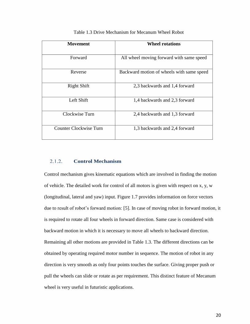
Table 1.3 Drive Mechanism for Mecanum Wheel Robot
Movement Wheel rotations
Forward All wheel moving forward with same speed
Reverse Backward motion of wheels with same speed
Right Shift 2,3 backwards and 1,4 forward
Left Shift 1,4 backwards and 2,3 forward
Clockwise Turn 2,4 backwards and 1,3 forward
Counter Clockwise Turn 1,3 backwards and 2,4 forward
Control Mechanism
Control mechanism gives kinematic equations which are involved in finding the motion
of vehicle. The detailed work for control of all motors is given with respect on x, y, w
(longitudinal, lateral and yaw) input. Figure 1.7 provides information on force vectors
due to result of robot’s forward motion: [5]. In case of moving robot in forward motion, it
is required to rotate all four wheels in forward direction. Same case is considered with
backward motion in which it is necessary to move all wheels to backward direction.
Remaining all other motions are provided in Table 1.3. The different directions can be
obtained by operating required motor number in sequence. The motion of robot in any
direction is very smooth as only four points touches the surface. Giving proper push or
pull the wheels can slide or rotate as per requirement. This distinct feature of Mecanum
wheel is very useful in futuristic applications.

21
Figure 1.7 Mecanum Wheel Layout: [6].
‘Vt’ is desired velocity and ‘ω’ is rotational velocity of platform and ‘r’ is given distance
from center of platform to wheel contact point.
M1, M2, M3, M4 are four sets of motor attached with respective wheels.
This gives the scalar components as:
𝑉𝑥 = 𝑉𝑡𝑥 − 𝜔 ∗ (𝑟 ∗ 𝑦)………………………………………………………………. (4)
𝑉𝑦 = 𝑉𝑡𝑦 − 𝜔 ∗ (𝑟 ∗ 𝑥)………………………………………………………………. (5)
The force vector analysis acting on right Mecanum wheel can be given in following
format.

22
Figure 1.8 Force Vector on Right Mecanum Wheel
To calculate Vω for right wheel:
cos 45 =𝑽
𝑽𝝎 … … … … … … … … … … … … … … … … … … … … … … … … … … … … … . … . . (6)
𝑽𝝎 =𝑽
cos 45 ………………………………………………………………………….. (7)
𝑽 = −𝑽𝒙 cos 45 + 𝑽𝒚 cos 45........................................................................................... (8)
𝑽𝝎 =−𝑽𝒙 𝐜𝐨𝐬 𝟒𝟓+𝑽𝒚cos 𝟒𝟓
cos 45 ……………………………………………………................. (9)
𝑽𝝎 = √2 (− 1
√2 𝑽𝒙 +
1
√2𝑽𝒚) …………………………….…………………………. (10)
𝑽𝝎 = −𝑽𝒙 + 𝑽𝒚 ………………………………………………………...……………. (11)
The two motors that use this wheel orientation are the right front & left rear.

23
𝑎 = 𝑟 ∗ 𝑥 …………………………………………………………...………………... (12)
𝑏 = 𝑟 ∗ 𝑦……………………………………………………………………………... (13)
Right front motor:
𝑉2𝑋 = 𝑉𝑡𝑋 − (𝜔 ∗ 𝑏)………………………………………………………………… (14)
𝑉2𝑌 = 𝑉𝑡𝑌 + (𝜔 ∗ 𝑎)………………………………………………………………… (15)
Left front motor:
𝑉3𝑋 = 𝑉𝑡𝑋 − (𝜔)(−𝑏)…………………………………………………………….... (16)
𝑉3𝑌 = 𝑉𝑡𝑌 + (𝜔)(−𝑎)……………………………………………………………… (17)
The force vector analysis on left Mecanum wheel is provided: [6].
Figure 1.9 Force Vector on Left Mecanum Wheel
The calculation of Vω for left wheel:
𝑽=1
√2 𝑽𝒙 +
1
√2𝑽𝒚 ……………………………………………………………………. (18)

24
𝑽𝝎 =|𝑽|
1
√2
… … … … … … … … … … … … … … … … … … … … … … … … … … … … … … … . … (19)
𝑽𝝎 = 𝑽𝒙 + 𝑽𝒚 … . … … … … … … … … … … … … … … … … … … … … … … … … … … … … . . (20)
Left front motor:
𝑉1𝑋 = 𝑉𝑡𝑋 − (𝜔) ∗ (𝑏)
𝑉1𝑌 = 𝑉𝑡𝑌 + (𝜔)(−𝑎)
Right rear motor:
𝑉4𝑋 = 𝑉𝑡𝑋 − (𝜔 ∗ 𝑏)
𝑉4𝑌 = 𝑉𝑡𝑌 + (𝜔 ∗ 𝑎)
The result for complete kinematic equations is given in following equations:
𝑉1𝜔 = 𝑉𝑡𝑌 + 𝑉𝑡𝑋 − 𝜔(𝑎 + 𝑏)
𝑉2𝜔 = 𝑉𝑡𝑌 − 𝑉𝑡𝑋 + 𝜔(𝑎 + 𝑏)
𝑉3𝜔 = 𝑉𝑡𝑌 − 𝑉𝑡𝑋 − 𝜔(𝑎 + 𝑏)
𝑉4𝜔 = 𝑉𝑡𝑌 + 𝑉𝑡𝑋 + 𝜔(𝑎 + 𝑏)
[*note: some values are given in bold letters, those parameters are vector quantities.]

25
Force Distribution on Mecanum Wheel Roller
Figure 2.0 Force Vectors on Single Roller: [7].
Figure 2.0 shows that the roller is attached to axle and plate at an angle of 45 degrees
which is given by α.
FC is the reaction force of floor on bottom of roller. FC has two components named FS &
Ff. FS gets counterbalanced by an equal but opposite force from wheel on other side of
vehicle. Ff is forward component which acts in the plane of Mecanum wheel. To counter
balance the torque action on wheel, FC must be equal to Ff /cos (α).
Mecanum Wheel Traction Factor
The forward force which comes from wheel is equal to the forward force which comes by
standard wheel of same dimension driven with same torque. In case of Mecanum wheel,
reaction force between floor and wheel is greater by a factor 1/cos (α). It allows wheel to
break the friction with floor and allows it to slip at lower forward force levels than a
standard wheel. This phenomenon makes Mecanum wheel to work with less friction.

26
Material for Roller
Rollers are manufactured with 75A – 85A polyurethane material. Polyurethane is a
polymer with numerous industrial applications because of its properties. On the inner side
of polyurethane wheel is the hard ABS material. These Mecanum rollers are also made
up of SBR rubber.
The others are manufactured by molding. As the material is perfect for melting and
pouring into molds which then gets the mold shape. This technology is an economical
way to manufacture the rollers. Then polyurethane and ABS are applied on each other’s
surface which makes ABS material to stick to polyurethane.
Polyurethane
It is polymer which consists of combination of small organic units of urethane links.
Polyurethane is selected to manufacture Mecanum wheel rollers set because it is
nonflexible, high performance adhesive and a hard plastic parts: [7]. Polyurethane rollers
are easy to manufacturing using dies and molds. They easily adopt the shape of the given
die to manufacture rollers or required product. In its simplest form, Polyurethane is a two
part material. These two parts are known as the pre-polymer and the curative. On their
own, they can be stored and generally used whenever they are needed. The polyurethane
used for manufacturing of Mecanum wheels is selected with hardness of 75A-80A. This
polyurethane is considered as thermoplastic polymer. It is easy to manufacture and use in
case of rollers.
The physical properties of polyurethane 75A are given in Table 1.4: [7].

27
Table 1.4 Physical Properties of Polyurethane
Physical Properties Units Value
Hardness - 75
Tensile Strength psi 4,600
Ultimate Elongation % 490
Split Tear pli 70
Resilience % 27
Tear Abrasion 1000 cycles - 40
Specific Gravity kg/m3 1.22
ABS Material
Acrylonitrile Butadiene Styrene commonly known as ABS is thermoplastic material. The
material is manufactured by varying the concentration of styrene and acrylonitrile in
presence of polybutadiene.
Some of the highlights of ABS material are given below:
Tough, rigid, hard
Creep resistant
Dimensional stability
High tensile strength and stiffness
Very high impact strength
Excellent high & low temperature performance
Excellent ductility
Chemical resistance

28
Table 1.5 ABS Material Properties: [8].
Properties Values / Units
Density 0.0376 kg/m3
Melt Flow 18 – 23 g/10 min
Hardness 103 -112 (in grade)
Tensile Strength 6160 – 6500 psi
Elongation at break 23 – 25 %
Flexural Modulus 326 – 331 ksi
Flexural Yield Strength 8790 – 10600 psi
Maximum service temperature 890C
SBR Rubber
SBR rubber is commonly used in application such as rollers. It is a mixture of Styrene
and Butadiene material.
Some highlights of SBR rubber are given below:
Excellent abrasion resistance
Excellent adhesion to metal
Adhesion to rigid material with excellent grip
Good at compression
Flex cracking resistance is good
Excellent tear resistance
Very good in vibration damping
Good steam resistance

29
Fair to weather exposure
Excellent water resistance
To know more about this material its properties are given in table 1.6
Table 1.6 Properties for SBR Rubber: [8].
Properties Values / units
Durometer / Hardness range 30 – 95 Shore A
Tensile strength length 500 – 3,000 Psi
Elongation % 450 % - 600 %
Low temperature range -51.110C to -34.440C
Brittle point -62.220 C
Maximum continuous use temperature 107.20 C
Mecanum Plate
Current Mecanum plate consists of aluminum material. Aluminum is selected as it is
strong and light in weight. It can be easily manufactured using sheet metal working and
pressing operation. It is not costly when it comes for manufacturing on large scale: [8].
Detailed analysis for Mecanum plate for given pressing operation with manufacturing
and assembly cost is given in DFMA analysis.
Brass Sleeve & Bearing
Brass sleeve plays an important role in assembly of roller to Mecanum plate. The
dimensions of every part is given in design parameters. These sleeves are connected to

30
bearing of same material and then to screws which then connect to the connector plate on
Mecanum wheel. When the force is applied on rollers it passes to bearing then to brass
tube and then onto Mecanum wheel: [9]. There are two brass tubes from which one is
used for ABS material. The other brass tube is attached on internal connections of screw
and connecting parts. The first tube is used as base on which ABS material part is
applied. ABS has good adhesive properties on metal.
Figure 2.1Dimensions of Brass Sleeve & Bearing: [9].

31
3. Kinematic Model
3.1. Model
Figure 2.2 Mecanum Robot and Wheel Specification with Co-Ordinates
The parameters are given below:
X, y, Ҩ which gives axes and rotation angle
XR , YR gives the frame which includes the system
Si Pi Ei with wheel’s center Pi these are the co-ordinate systems
lix, liy distance between wheels from center and rear wheel

32
ri gives the actual radius of wheel named i
rr roller wheel radius
αi gives angle in OPi and XR
βi the given angle of Si and XR
γi angle given in vir and Ei
ωi angular velocity of wheels
viω [m/s] (i = 0,1,2,3) € R
vx, vy [m/s] – linear velocity for given robotic motion
ωz [rad/s] – angular velocity for given robotic motion
Velocity of wheel:
𝑉𝑖𝑟 =1
cos 45(𝑟2) ∗ (𝜔 ∗ 𝑖)
𝑉𝑠𝑖 = 𝑉𝑖𝑟 ∗ (sin 𝛾 ∗ 1)
𝑉𝑒𝑖 = (𝜔 ∗ 𝑖) ∗ (𝛾 ∗ 𝑟) + 𝑉𝑖𝑟 cos 𝛾𝑖
3.2. Forces
The force generated by motor drives the shaft which is connected to Mecanum wheel.
From there it goes to rollers on their axis. This force acts with some angle to plane wheel.
It is required to consider two co-ordinate system x & y: [10].
Following diagram shows the force vectors on each wheel. All the forces are distributed
into x and y co-ordinate system with vector representation. The length from center of
robot to the wheel is given with length ‘l’ in mm.
The force distribution on each wheel is given in Figure 2.3.

33
Figure 2.3 Force Distribution: [10].
The total force is divided into 2 components
𝐹𝑡𝑥𝑖 = ∑ 𝐹𝑥𝑤
4
𝑤=1
𝑖
𝐹𝑡𝑦𝑗 = ∑ 𝐹𝑦𝑤
4
𝑤=1
𝑗
Where ‘i’ & ‘j’ are unit vectors.
The rotational motion that occurs at the point (0, 0) gives torque as,
𝜏 = (−𝐹𝑥1 − 𝐹𝑥2 + 𝐹𝑥3 + 𝐹𝑥4)𝑙𝑦 + (𝐹𝑦1 − 𝐹𝑦2 − 𝐹𝑦3 + 𝐹𝑦4)𝑙𝑥
Where lx & ly are radii at which forces are applied: [11].
The relation of velocity and force is given as:
𝑉 ⋉ ∑ 𝐹𝑤
4
𝑤=1
34
3.3. Wheel Velocity
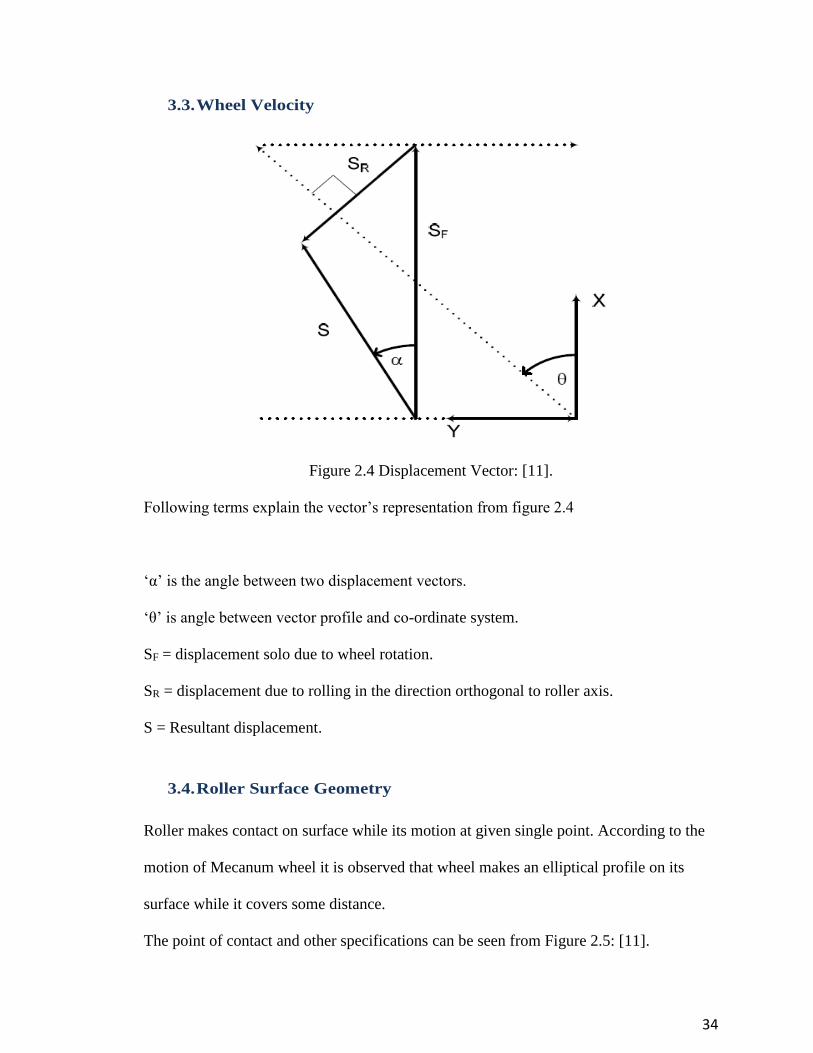
Figure 2.4 Displacement Vector: [11].
Following terms explain the vector’s representation from figure 2.4
‘α’ is the angle between two displacement vectors.
‘θ’ is angle between vector profile and co-ordinate system.
SF = displacement solo due to wheel rotation.
SR = displacement due to rolling in the direction orthogonal to roller axis.
S = Resultant displacement.
3.4. Roller Surface Geometry
Roller makes contact on surface while its motion at given single point. According to the
motion of Mecanum wheel it is observed that wheel makes an elliptical profile on its
surface while it covers some distance.
The point of contact and other specifications can be seen from Figure 2.5: [11].

35
Figure 2.5 Roller Profile: [12].
Figure 2.5 shows that as widest part is the point of contact on surface and roller is at 450
to the surface it makes a curved point of contact profile on its surface. The maximum
load applied to roller get of most of its impact at this given point. Red dots on roller
surface are the point which touches ground while roller moves. The profile given by the
red dots is not in straight line as the roller axis is 450. At any given point we get four
points of each roller touching surface below it.

36
4. Manufacturing
4.1. Wheel Plate
The wheel plate is designed by considering its strength and weight at the same time. The
material considered for manufacturing of plate should be able to satisfy these two given
conditions. The material selected for manufacturing plate is Aluminum. Aluminum is
very good for its properties and perfect material for manufacturing of plate.
The main plus points of selecting Aluminum for manufacturing of Mecanum plate are
given below:
1. Aluminum is almost 1/3rd in weight as compared with other competitive materials.
2. Aluminum is excellent corrosion and oxidation resistant.
3. Aluminum has high thermal conductivity.
4. Aluminum costs less as compared to other metals or alloys.
5. Aluminum is fairly soft and easy to mold in given shape as it is more malleable.
6. Aluminum is difficult to weld but our application does not need any kind of
welding of Mecanum plate. This factor can be easily neglected.
7. Aluminum is non-magnetic material. It gives good impact on robot applications.
Stamping for Mecanum Plate
The manufacturing process selected to manufacture plate is stamping. Stamping is used
to manufacture parts which can be molded easily by use of die and given material. The
selected material is placed between two dies and which cuts and shapes the given
material into required shape.

37
4.2. Rollers
The selected material is polyurethane, ABS and SBR rubber. Their application is to make
rollers with given specific dimensions. These materials can be melted, molded and
shaped depending upon required manufacturing and application. Though all rubbers does
not melt but our selected material is perfect example for manufacturing of rollers by
using die & mold manufacturing or extrusion manufacturing method which can be melted
and molded easily.
Molding Operation
Molding process is used in manufacturing of rubber or polymer applications. The hot
melted material is poured through feeder into the die which is made considering the given
dimensions of product. Once the material is poured into the die it is allowed to set for
some time and to take the shape of the die. After the material is cooled down it is taken to
polishing.
Molding operation gives the given required shape but it is not guaranteed that the
outcome of molding is a final product which can be used directly. As the edges contain
extra rubber or unwanted string type material on edges. This is removed before attaching
roller on Mecanum wheel.
4.3. Brass Sleeves
Brass is ductile. Brass sleeves are used in this application because brass is excellent
corrosion resistance. The best way to manufacture brass sleeves is extrusion. Extrusion is
used for metals which are easy to elongate and moldable.

38
5. Experiment to Determine the Coefficient of Friction
5.1. Overview
The experimental setup consists of series of different base conditions to obtain values of
friction on Mecanum wheel rollers. Setup consists of friction calculation machine on
which Mecanum wheel rollers are mounted to find coefficient of friction. The test is
conducted in university’s lab facility under proper safety conditions. The experiment
gives both values of static friction and kinetic friction on rollers. However once the
rollers are in motion only the kinetic friction is calculated. According to the law of
physics the value of static friction is always more than value of kinetic friction. When any
object at rest is displaced in any given direction it is necessary to apply more force to
move the object from rest.
The experiment work is conducted in following order:
1. Roller attachment with machine bed
2. Application of load on roller
3. Measuring friction coefficient by use of load cells
4. Applying different conditions to find friction
The machine setup is consist of:
1. Bed of machine
2. Clamps
3. Load cell
4. Gauge

39
5. Rollers (from Mecanum wheels)
6. Attachments from clamp to rollers
7. Fixtures
8. Dynamometer
9. Tribometer
The setup consist of machine unit which is capable of taking load to maximum value of
454 kg. The purpose of this experiment is to find values of roller’s coefficient of friction
from the range of 0.4535 kg to 68 kg in all considered conditions. Following conditions
are selected for the experiment as all the conditions are applicable in actual working of
robotic vehicle. If the robot is used in industry or navy ship where it climbs on iron walls,
these conditions will give the most suitable C.O.F values.
The test is conducted to find out friction coefficient in conditions as:
1. Friction on concrete surface
2. Friction on aluminum
3. Friction on wet surface (on water)
4. Friction on wooden surface
5. Friction on painted surface
6. Friction on ice
7. Friction on hot surface (65.55o C)
8. Friction on greasy surface
9. Friction on sand paper with grit – 220

40
Experiment Process
- The rollers have sub-assembly of inner bearing, screw and washer on both ends and
covered with polyurethane and ABS material on top of all.
- When considered to calculate friction on separate roller it is important to consider the
way force gets applied to the roller.
- The wheel consists of 16 slots with 16 rollers on it. The position of rollers is such that
it makes 45 degrees angle with surface where they touch the wheel.
- While attaching the roller on experimental setup it is important to make sure that the
roller comes in exact same position as on an actual robot when it is in motion.
- The roller is then attached to the external setup which then connects to connecting
bar. This connecting bar continues till it gets attached to the bottom of the clamp
where the machine is going to apply pressure.
- The connecting bar works such as it will rotate the wheel on the bed of machine. The
rollers will rotate on work bench without any external force acting on them.
- Due to the setup the acted force will be applied on roller by connecting bar.
- After making sure that the connection is correct, action is taken to calibrate the
machine so that the initial force applied on roller is zero.
- Once the setup is completed the experiment can be conducted step by step.
- The machine is capable of reading the friction and give the result on display bar.
- The coefficient of friction is given as kinetic friction.
- Includes load cell in machine itself.
- The load cell gives the average load applied on the part.

41
Machine Specification
Table 1.7 Friction Tester Specification
Bed Length 650 mm
Bed Width 350 mm
Span Adjustment 10 -160 mm
Force (max) 1000 N
Speed Accuracy +/- 0.2% of selected speed
Supply Voltage (+/- 10%) 115VAC/230VAC
Max Power Required 150VA
Load Cell
Load cell is a device which is used to calculate the strain value applied on it. It measures
the applied load and gives magnified output value of applied force. It works on
contraction and expansion base where small amount of variation is detected.
Tribometer
Tribometer is used to find the value of coefficient of friction, wear and tear between two
contacting surfaces. The principle used in Tribometer is application of mass until the
object start to move. In case study it is observed that the coefficient of friction is the ratio
of two masses.
Coefficient of Friction
Traction of roller on the Mecanum wheel is given by equation, µ × P
Where, µ is the coefficient of friction for polyurethane roller and track of contacting
surface and P is the load on roller.

42
Figure 2.6 Tools for Experiment
Figure 2.7 Roller with Attachment for Experiment

43
Figure 2.8. Mecanum Wheel of 6”
Figure 2.9. Mecanum Wheel of 9”

44
Figure 3.0 Surface Bed to Calculate C.O.F
Figure 3.1 Experiment Tool for Length Measurement

45
Case 1 - Coefficient of Friction on Concrete Base
The case is studied for polyurethane wheel on rough concrete surface. Concrete is a very
strong material which gives wheel or rollers a good grip on it. This case is considered if
roller is moving on a concrete for a while for transporting.
Mecanum wheel is made up of polyurethane material which will get excellent grip on
concrete surface as concrete has rough surface of contact. To overcome this friction
force, Mecanum wheel needs more driving force as a result, there will be more friction.
The experiment is conducted on test bed to find the value of frictional coefficient
between these two surfaces. The test is taken from 0.4535 kg to 68.03 kg. The result of
test is given in Figure 3.2.
All the values in chart are calculated for kinetic friction as roller was moving on machine
bed.
Figure 3.2 Coefficient of Friction on Concrete Surface
0.31
0.53
0.6
0.75
0
0.1
0.2
0.3
0.4
0.5
0.6
0.7
0.8
1 50 100 150
Co
eff
icie
nt
of
Fric
tio
n
LOAD
C.O.F ON CONCRETE SURFACE

46
Case 2 - Coefficient of Friction on Aluminum Plate
Aluminum metal comes in different composite forms. This test is conducted for the
regular aluminum sheet which does not include any other material as composite with
aluminum. Aluminum is used for various applications like cans, frames, foils, airplane
parts. Aluminum is excellent corrosive resistant and it is non-magnetic. Aluminum
surface is rough as seen under microscope. Its surface contains peaks and valleys which
make it good on friction part.
Properties of Aluminum:
Melting point – 660.20C
Boiling point – 24800C
Thermal conductivity – 0.57 cal/g.0C)
Density – 2.6898 g/cm3
Modulus of elasticity – 68.3 GPa.
Aluminum frame was taken and fixed with precaution in the fixture to ensure that there
are no loose parts while experiment is being conducted. If aluminum is kept in fixture
with no proper tightening of the test bed, there will be an error.
The experiment is conducted on aluminum plate with 3 different sets of readings. The
final value of C.O.F on aluminum plate is average of all the readings. The purpose behind
it is to get the most accurate value. Same roller is used to find all sets of readings
because; the same rollers set will be used again and again.
The graphical representation of final result is given in Figure 3.3.

47
Figure 3.3 Coefficient of Friction on Aluminum
Case 3 - Coefficient of Friction on Wet Surface
The experiment is carried out by applying water on the test bed. The addition of water
makes the surface skiddy. In terms of friction, as the surface is more slippery there will
be less friction between two surfaces. This test is important as Mecanum wheels can be
used in outside environment where rollers will directly come in contact with water and as
the robot will move through the wet surface, it should have good grip so that if robot
needs to stop abruptly, it will be possible to apply quick stop.
This test is rated amongst the most important one as rollers can come in contact with
water on regular basis. If the robot is used on submarine’s outer surface for any special
purpose task, these values play important role in it. The graphical representation of the
test result is shown in Figure 3.4.
0.2
0.29
0.38
0.45
0
0.05
0.1
0.15
0.2
0.25
0.3
0.35
0.4
0.45
0.5
1 50 100 150
Co
effi
cien
t o
f Fr
icti
on
LOAD
C.O.F on Aluminum Surface

48
Figure 3.4 Coefficient of Friction on Wet Surface
Case 4 - Coefficient of Friction on Finished Wooden Plate
The experiment for finding friction on wooden plate, the plate is polished by using sand
paper to make the surface even. Making the surface straight and even helps to calculate
actual C.O.F.
The plate used in this case is 60 mm × 75 mm which is mounted on the fixture. The
thickness of plate is kept as 10 mm. If we consider plate with thickness less than 10 mm,
it may fail when a force of more than 68.03 kg is applied. This test is performed with
consideration of robot working in forest area and it has to cover specific distance through
woods.
The resulted graph for C.O.F values in case of wooden surface are given in Figure 3.5.
0.15
0.22
0.28
0.32
1 50 100 150
Co
eff
icie
nt
of
Fric
tio
n
LOAD
C.O.F on Wet Surface

49
Figure 3.5 Coefficient of Friction on Wooden Surface
Case 5 - Coefficient Friction on Painted Surface
The experiment is conducted by using a metal frame with spray painting on its surface.
The name of paint used for this experiment is ‘Rust-oleum umber spray’. The purpose of
selecting this paint is given with specifications.
This color is rich in finish.
It is great on wood or metal surface as it gets equally spread on both surfaces.
It does not cause fatigue on surface which serves great purpose on larger load of
68.03 kg.
This paint is durable and corrosion resistant with high end looks.
It costs less than $8 per bottle.
0.1
0.17
0.21
0.23
0
0.05
0.1
0.15
0.2
0.25
1 50 100 150
Co
eff
icie
nt
of
Fric
tio
n
LOAD
C.O.F on Wooden Surface

50
The graphical representation of C.O.F for painted surface is given in Figure 3.6.
Figure 3.6 Coefficient of Friction on Painted Surface
Case 6 - Coefficient of Friction on Ice
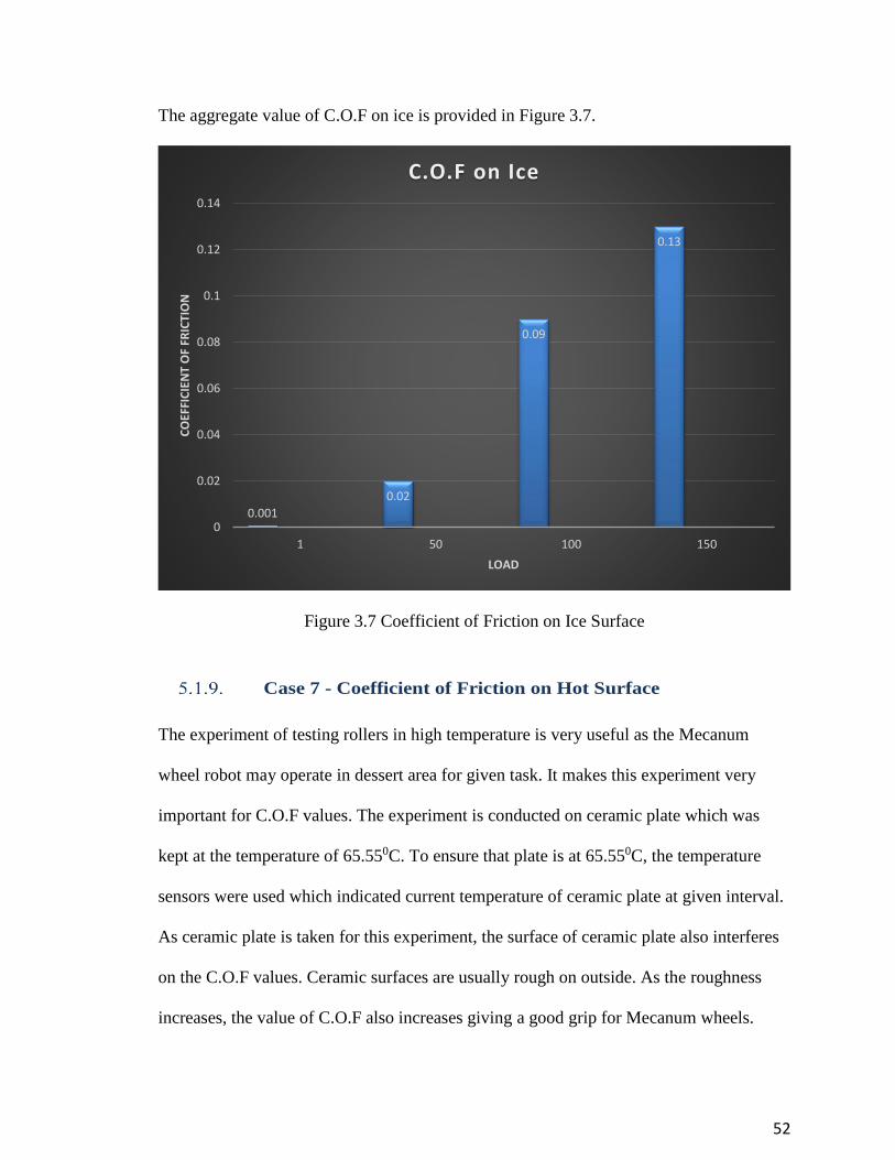
This experimental test is little different than other tests. The base surface used to find
C.O.F is ice. Ice is considered to be very slippery with very less traction. The term
traction explains that the contacting area of rollers and ice do not give friction as we got
in the case of concrete or metal surfaces. The area of ice keeps changing its top surface
form all the time because of atmospheric temperature. The ice form used in the test is
different than ice on which roller will be actually used. The difference is that, the ice on
which the roller will move is not the same ice as experimental. The value of coefficient of
friction in case of actual working of robot will change. While testing coefficient of
friction value, ice was melting constantly making it difficult to take reading. To conduct
0.09
0.22
0.36
0.42
0
0.05
0.1
0.15
0.2
0.25
0.3
0.35
0.4
0.45
1 50 100 150
CO
EFFI
CIE
NT
OF
FRIC
TIO
N
LOAD
C.O.F on Painted Surface

51
this part of the experiment, trial and error method of verification was used to find the
actual C.O.F value.
Some of the initial difficulties faced are mentioned in following list:
Difficulty in holding the ice cube on bed of the machine.
Maintaining the ice cube location at the same place.
Keeping the maximum thickness of ice cube more than 10 mm so that it will not
break under high loads.
Keeping the room temperature under normal room temperature to prevent ice
from melting.
Keeping roller dry for different set of reading in trial and error method.
Avoiding the contact of ice with other materials.
In situation like ice coming in contact with oil or grease, it will change the value
of coefficient of friction on ice.
Real time values of C.O.F on ice are far different than experimental values as the
ice form in real time is not in solid shape. It comes as small crushed dust like
particles.
Working condition of rollers on icy surface can be considered as extreme because;
the main factor which is evaluated in the experiment is coefficient of friction and
ice has the lowest friction value with roller as it is seen in the experimental
results.
To overcome this problem, the roller surface needs to be given some gripping
design or screw mounting on its surface.
52
The aggregate value of C.O.F on ice is provided in Figure 3.7.
Figure 3.7 Coefficient of Friction on Ice Surface
Case 7 - Coefficient of Friction on Hot Surface
The experiment of testing rollers in high temperature is very useful as the Mecanum
wheel robot may operate in dessert area for given task. It makes this experiment very
important for C.O.F values. The experiment is conducted on ceramic plate which was
kept at the temperature of 65.550C. To ensure that plate is at 65.550C, the temperature
sensors were used which indicated current temperature of ceramic plate at given interval.
As ceramic plate is taken for this experiment, the surface of ceramic plate also interferes
on the C.O.F values. Ceramic surfaces are usually rough on outside. As the roughness
increases, the value of C.O.F also increases giving a good grip for Mecanum wheels.
0.001
0.02
0.09
0.13
0
0.02
0.04
0.06
0.08
0.1
0.12
0.14
1 50 100 150
CO
EFFI
CIE
NT
OF
FRIC
TIO
N
LOAD
C.O.F on Ice

53
The values of C.O.F for hot surface are given in Figure 3.8.
Figure 3.8 Coefficient of Friction for Hot Surface at 65.550C
Case 8 - Coefficient of Friction on Greasy Surface
The experiment is conducted with covering the bed of the machine with grease. Addition
of grease to the surface makes it extremely slippery. If the surface is more slippery, less
will be the coefficient of friction.
The results of this case study are compared with the case of ice and grease, in both cases
the surface area in contact with roller makes the friction very negligible. If the roller is
carrying heavy load of 90.71 kg it will make it difficult for the robot to operate. For the
solution, it is required to consider other roller material or increase the grip on roller by
making few changes on its outer surface.
The graphical representation of these values are shown in Figure 3.9.
0.092
0.12
0.22
0.27
0
0.05
0.1
0.15
0.2
0.25
0.3
1 50 100 150
CO
EFFI
CIE
NT
OF
FRIC
TIO
N
LOAD
C.O.F ON HOT SURFACE (65.55OC)

54
Figure 3.9 Coefficient of Friction on Greasy Surface
Case 9 - Coefficient of Friction of Rollers on Sand Paper with
Grit-220
This case study elaborates more on the contact between polymer material and rough sand
paper. Sand paper comes in different surface finishes according to its use. Superfine sand
paper is used for polishing purpose. Sand paper grit ranges between 40– 600.
The different sand papers are shown in Figure 4.0 and Figure 4.1. Grit 40 is rough while
grit 600 is extremely polished.
0.0114
0.035
0.08
0.13
0
0.02
0.04
0.06
0.08
0.1
0.12
0.14
1 50 100 150
Co
eff
icie
nt
of
Fric
tio
n
LOAD
C.O.F on Grease

55
Figure 4.0 Sandpaper with Grit-40: [13].
Figure 4.1 Sandpaper with Grit-600: [13].

56
The obtained values of C.O.F on sand paper are represented in Figure 4.2.
Figure 4.2 Coefficient of Friction on Sand Paper with Grit - 220
Figure 4.2 shows high values of C.O.F by using concrete, metal and sand paper. The
purpose of using material with high roughness is to observe wear and tear of rollers. As
64 rollers roll at given specific time when Mecanum wheel robot moves, it is very
important to see the life span of the rollers and factors affecting its performance.
To determine the life span of polyurethane rollers, different environmental conditions are
tested to verify results.
To explain the behavior of friction, following chart is given which compares friction
values with increase or decrease of given factors in chart.
0.37
0.48
0.62
0.8
0
0.1
0.2
0.3
0.4
0.5
0.6
0.7
0.8
0.9
1 50 100 150
Co
effi
cien
t o
f Fr
icti
on
LOAD
C.O.F on sand-paper with grit 220

57
Table 1.8 Important Friction Factor: [14].
To increase friction Factor To decrease friction
Increase Unit load Decrease
Increase Surface finish Decrease
Decrease Speed of motion Increase
Increase Pressure Decrease
Omit Lubrication Use
Decrease Temperature Increase
To ensure that the experimental results are correct, it is important to verify the values of µ
with previous experimental values.
Following table shows the result compared with actual values of coefficient of friction
with given condition.
Table 1.9 Friction Value Comparison
Material Base Coefficient of Friction Calculated
in Experiment (average)
Given Coefficient of Friction
by Previous Experiments
Concrete 0.65 0.71
Aluminum 0.40 0.45
Wet Surface 0.30 0.34
Wooden Surface 0.21 0.29
Painted Surface 0.35 0.30
Ice 0.08 0.059
Hot Surface (65.550C) 0.19 0.15
Grease 0.06 0.010
Sand Paper 0.67 0.75

58
6. Mecanum Wheel Life Span
Polyurethane is one of the best polymers that can be used for production of rollers
because of its properties. The way to produce such wheels using mechanical
manufacturing process is either casting or molding. Molding process is efficient & more
practical than casting for manufacturing of rollers: [14]. Molding consists of injection of
melted material, in which given hot melted polymer is poured through a given feeder area
into the mold and kept to settle for some time. It gets the shape of the mold as it cools
down. The inner face of roller consists of ABS material which is thin layer between
polyurethane and bearing. The ABS polymer acts as adhesive which binds polyurethane
and bearing so they never slip on each other’s surface. ABS is categorized under
thermoplastics: [14].
Some important properties of ABS polymer:
High impact resistance
Toughness factor is high
Doesn’t peel off at extreme low or high temperature
6.1. Side Peel of Rollers
Material selection and friction test are important factors to be considered for the working
of rollers. The other important factor to be considered is side peel test of roller material:
[15]. Side peel test of roller can be explained as the wear and tear of material that occurs
under high load or temperature.
The experiment is conducted on peel tester experimental setup to obtain constant friction
between roller’s side edges and the machine on which it is tested.

59
Theory for Side Peel Effect
- The machine used to find the side wear and tear of roller consists of test bed, vertical
loading unit and clamps.
- The roller is fixed in clamp such that the roller axis is exactly perpendicular to the test
bed.
- It is ensured that the complete edge of roller touches the setup to take correct values.
- The roller is then constantly contacted by rotational motion with constant application
of force on it from vertically mounted load unit.
- The value of load is gradually increases from 0.45 kg to 68.03 kg.
Observations & Results
According to the test, the material starts to peel out when load reaches its maximum value
of 68.03 kg considering that the wheel is continuously tested for 1 hour with the
maximum load. The tested specimen roller start to show wear on its edges when the
roller’s surface reaches its highest temperature range after which the material fails to
perform.
Main problem observed in test was that the adhesiveness or bonding between polymer
and bearing is not sufficient. To improve the process and reduce the early peeling of
material from roller and to increase strength of roller, following suggestions are given.
Figure 4.3 shows the roller’s surface after it has been tested for peeling effect in condition
of high load and change in temperature.
The material starts to peel after 1 hour of continuous rubbing with surface which suggests
that if roller is working in a hot environment and running over surface with maximum
friction like cement, it will damage the roller’s surface quickly.

60
Figure 4.3 Wearing of Roller
Given suggestions to reduce wear and tear for roller:
1) Design the roller’s edges such that the point of contact of roller’s edge will never
touch the ground to avoid the chance of side peel effect.
2) The addition of adhesive material between polymer and bearing to make both
surfaces stick to each other more firmly and to make the roller strong for its
overall performance in such extreme working conditions.

61
7. Design for Manufacturing and Assembly
The manufacturing of the Mecanum wheel is done with following norms to calculate total
estimated cost for manufacturing and assembly. To find out the cost for manufacturing
and assembly, the design of complete Mecanum wheel is imported into DFMA software.
First software estimates Design for Manufacturing values and the other software
estimates the Design for Assembly values.
DFMA software includes license that can be downloaded from authorized website. It can
take design input from most of the leading software such as CATIA, ANSYS,
SolidWorks and AUTOCAD.
7.1. DFM
Design for Manufacturing software deals with the way a part that can be manufactured. It
is used to calculate the material dimension, process to be used to find out best machining
operation to manufacture that part and the remaining additional costs that are related to it.
DFM software takes the input from user and analyzes the output based on its coding.
The output values by use of DFM software can calculate cost which are close to 85% of
the actual cost. Use of DFM software is beneficial as it gives all required data without
even the manufacturing part initially.
DFM can take input from CAD based design software. The other way to use this software
is that user should know the largest dimension of given part. DFM software is built with
manufacturing processes and material selection over a wide range. Importantly, the
software calculates all hidden costs and expenditures which are used while manufacturing
a given part.
The user interface of DFM software is shown in Figure 4.4.

62
Figure 4.4 User Interface of DFM Software
The four stages in DFM software:
1. Part
2. Envelope shape
3. Approximate envelope dimensions
4. Select process and material
63
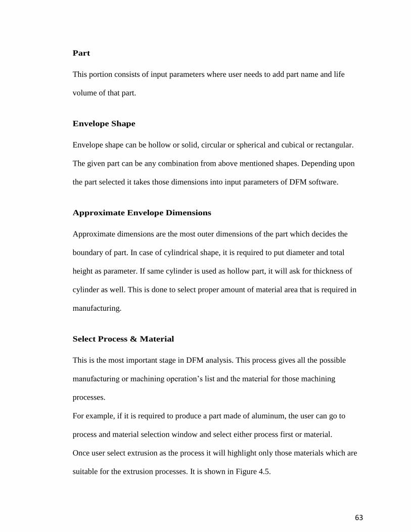
Part
This portion consists of input parameters where user needs to add part name and life
volume of that part.
Envelope Shape
Envelope shape can be hollow or solid, circular or spherical and cubical or rectangular.
The given part can be any combination from above mentioned shapes. Depending upon
the part selected it takes those dimensions into input parameters of DFM software.
Approximate Envelope Dimensions
Approximate dimensions are the most outer dimensions of the part which decides the
boundary of part. In case of cylindrical shape, it is required to put diameter and total
height as parameter. If same cylinder is used as hollow part, it will ask for thickness of
cylinder as well. This is done to select proper amount of material area that is required in
manufacturing.
Select Process & Material
This is the most important stage in DFM analysis. This process gives all the possible
manufacturing or machining operation’s list and the material for those machining
processes.
For example, if it is required to produce a part made of aluminum, the user can go to
process and material selection window and select either process first or material.
Once user select extrusion as the process it will highlight only those materials which are
suitable for the extrusion processes. It is shown in Figure 4.5.
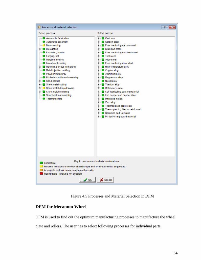
64
Figure 4.5 Processes and Material Selection in DFM
DFM for Mecanum Wheel
DFM is used to find out the optimum manufacturing processes to manufacture the wheel
plate and rollers. The user has to select following processes for individual parts.

65
Mecanum Plate
The process selected for Mecanum plate is stamping. As user can make dies for plate
material and using stamping as process the user can manufacture these plates in the
quickest way possible. The next step is to apply given material to plate. As expected
target is to produce Mecanum wheel with less weight because of the total weight
constraint, user needs a light weight material that is strong and stable at the same time. It
can be selected from a wide variety of Aluminum alloys. After selecting machining
process and material, analysis is carried on it. The same process is repeated with the
roller for its polymer material.
7.2. DFA
DFA stands for ‘Design for Assembly’. DFA is used to calculate the assembly cost of a
given part. The assembly cost can include the labor cost, material cost, special machining
cost, scrap cost and time for processing given operation on relative machine. Advantage
of using DFA is that it can import DFM files directly into its system.
DFA consists of the following steps:
1. Assembly part insertion
2. Selection of part number and its repeat count
3. Item specification (weight limit)
4. Dimensioning of part
5. Item function (the way it is connected with other parts in the assembly)
6. Symmetry of that part (either no axis, one axis, two axis)
7. Handling requirements
8. Handling difficulties

66
9. Securing process (the process with which it is attached or fastened)
10. Operation characteristics
11. Manufacturing data (with piece part cost, item cost and tooling investment)
The following guidelines are applied to the DFA analysis on the given part.
The schematic representation about the steps is given in Figure 4.6.
Figure 4.6 DFA Software Analysis Chart

67
Comparison of Different Materials Using DFM Analysis
The following chart shows the different material which can be used as a roller material
and gives the total investment for each selected material. The comparison is done with
factors such as material value, setup cost, rejected parts cost, tooling cost, total
manufacturing cost and the complete investment cost.
Table 2. DFM Analysis of Roller Material
High
impact
Polystyrene
($)
High
Density
Polyethylene
($)
ABS
($)
Ethylene
Propylene
($)
Silicone
Shore
70
($)
Ethylene
Propylene
Diene
Monomer
($)
Material 0.02 0.01 0.03 0.06 0.06 0.05
Setup 0.05 0.05 0.05 0.05 0.05 0.05
Process 1.24 0.61 1.17 1.15 1.05 1.68
Rejection 0.01 0.00 0.01 0.01 0.01 0.01
Piece Part 1.31 0.68 1.26 1.27 1.17 1.79
Tooling 1.23 1.23 1.23 1.23 1.23 1.90
Total 2.55 1.91 2.49 2.50 2.41 3.68
Total
Investment
14,471
12,333
14,471
12,333
12,333
18,984

68
8. Conclusion
The following are conclusions based on this research:
1. Aluminum is selected as the material for manufacturing of Mecanum plate. ABS
and Polyurethane are selected for Mecanum rollers. Polyurethane 75A polymer
has high tensile strength of 4,600 psi and split tear resistance of 70 pli. ABS
polymer has high density value of 0.0376 kg/m3 and it works at maximum
temperature of 890C.
2. The current work is done for the maximum limit of 68.03 kg on rollers. This is the
maximum load application to estimate the values of coefficient of friction.
3. Experiments are done to find the coefficient of friction of the rollers with different
surfaces. The high values of coefficient of friction are produced by concrete
surface and the sand paper surface as 0.65 and 0.67 respectively. The rollers are
tested on ice and grease. It gave the least values of coefficient of friction as 0.08
and 0.06 respectively.
4. The DFMA software is used to find the Design for Manufacturing and Design for
Assembly costs. Design for Manufacturing estimated the total product cost for
Mecanum plate came as $49.38. The total tooling investment for Mecanum plate
manufacturing came as $9,453.
5. Design for manufacturing cost for Mecanum wheel rollers gave total product cost
per part as $0.57 and initial tooling investment with $28,443.
6. Design for assembly for Mecanum rollers estimated total assembly labor time as
12.91 seconds and total processing cost per part as $0.46.
69
9. Future Suggestions
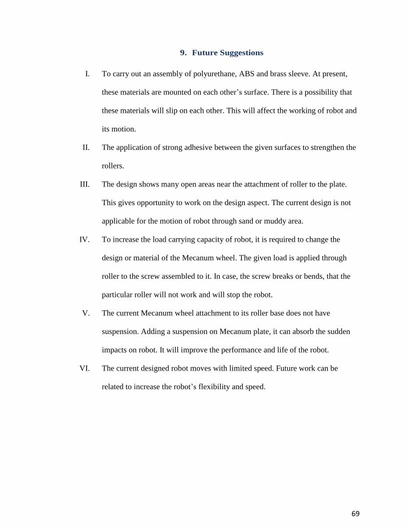
I. To carry out an assembly of polyurethane, ABS and brass sleeve. At present,
these materials are mounted on each other’s surface. There is a possibility that
these materials will slip on each other. This will affect the working of robot and
its motion.
II. The application of strong adhesive between the given surfaces to strengthen the
rollers.
III. The design shows many open areas near the attachment of roller to the plate.
This gives opportunity to work on the design aspect. The current design is not
applicable for the motion of robot through sand or muddy area.
IV. To increase the load carrying capacity of robot, it is required to change the
design or material of the Mecanum wheel. The given load is applied through
roller to the screw assembled to it. In case, the screw breaks or bends, that the
particular roller will not work and will stop the robot.
V. The current Mecanum wheel attachment to its roller base does not have
suspension. Adding a suspension on Mecanum plate, it can absorb the sudden
impacts on robot. It will improve the performance and life of the robot.
VI. The current designed robot moves with limited speed. Future work can be
related to increase the robot’s flexibility and speed.

70
REFERENCES
[1] Fiegel, O., A. Badve and G. Bright, et al. “Improved Mecanum Wheel Design for
Omni-Directional Robots”. Proc Australasian Conf. Robotics & Automation, 27-
29 Nov. 2002.
[2] Shigley, J. E., and Mischke, C. R., Mechanical Engineering Design, McGraw-Hill
Inc., New York, 1989.
[3] Badve AA. All Terrain Omni-Directional Autonomous Mobile Robot, Master’s
Thesis, Massey University, Aukland, New Zealand 2003.
[4] Dubowsky, S., Genot, F., Godding, S., Kozono. H, Skwersky, A., Yu, H., and Yu, L.,
“PAMM – A Robotic Aid to the Elderly for Mobility Assistance and Monitoring:
A Helping-Hand for the Elderly”. IEEE International Conference on Robotics and
Automation. pp. 47-52. 2001.
[5] M. de Villiers, G. Bright., Council for Scientific & Industrial Research, Pretoria
“Development of a Control Model for a Four Wheel Mecanum Vehicle”, pp. 1-7.
2008.
[6] AndyMark.com, Mecanum Wheels – AndyMark. N.P., 2015.
[7] Hamid Tahedi, Bing Quio., “Kinematic Model of a four Wheeled Mobile Robot”, pp
1-2. 2007.
[8] Keith Schlee, Mecanum Wheel Summary, Helical Robotics. 2009.
[9] Dewan Muhammad Nuruzzaman, Mohammad Asaduzzaman, “Friction & Wear of
Polymer and Composite”, http://dx.doi.org/10.5772/48246, pp.1-19. 2003.
[10] Laumond, J.P., 1998, “Robot Motion Planning and Automation”, 2006. Vol. 10,
No.4, pp. 480-489. 2008.
[11] West, M., and Asada, H., “Design of Ball Wheel Mechanism for Omnidirectional
Vehicles with Full Mobility and Invarient Kinematics”, Journal of Mechanical
Design, Vol. 119, pp. 153-161. 2002.
[12] Kim, K. U., and Shin, B. S. “Modeling Motion Resistance of Rigid Wheels.” Journal
of Terramechanics, 22(4), pp. 225-236. 1986.
[13] M. de Villiers, N. S. Tlale, “Development of a Control Model for a Four Wheel
Mecanum Vehicle”, J. of Dynamic Systems, Measurement, and Control, 134
011007, 2012.

71
[14] P. F. Muir and C. P. Neuman, “Kinematic Modeling of Wheeled Mobile Robots”,
Technical Report CMU-RI-TR-86-12, Robotics Institute, Carnegie Mellon
University, June 1986.
[15] Online: http://www.cord.edu/dept/physics/p128/lecture99_12.html, web site of the
Physics, Department at Concordia University containing physics lectures, 2011.

72
APPENDIX A
This section contains the results from DFM analysis on Mecanum Plate.
Figure 4.7 Manufacturing Cost per Product

73
Figure 4.8 DFM Cost Breakdown
74
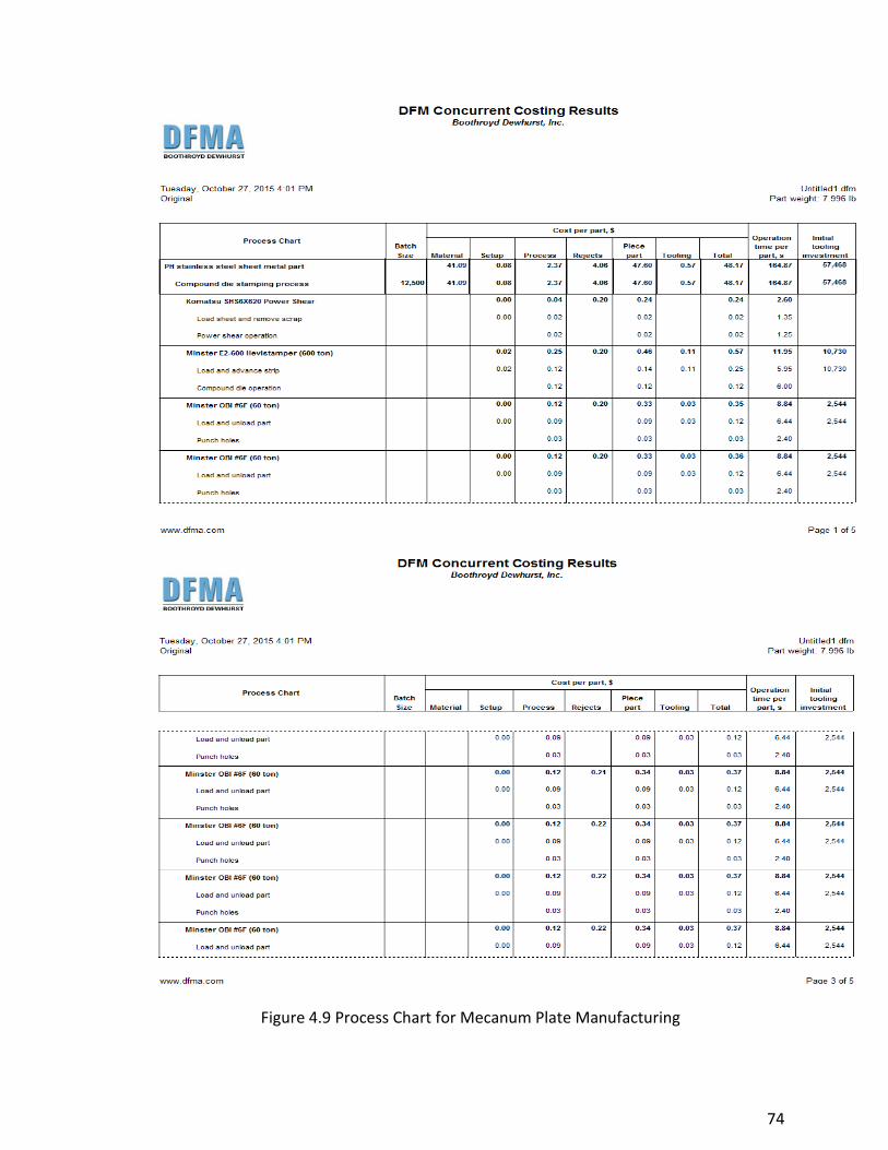
Figure 4.9 Process Chart for Mecanum Plate Manufacturing

75
APPENDIX B
This section contains the results from DFM analysis on Mecanum rollers.
Figure 5.0 DFM Analysis for Injection Molding

76
Figure 5.1 DFM Report for Manufacturing Factors of Roller
77
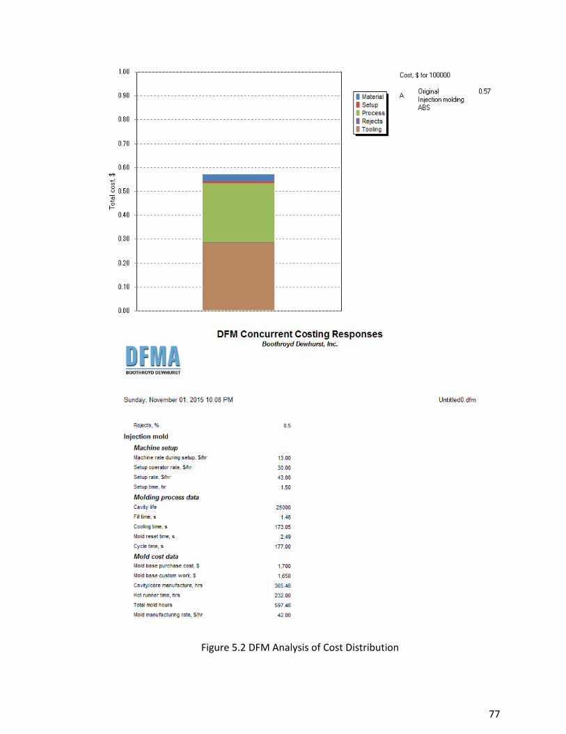
Figure 5.2 DFM Analysis of Cost Distribution

78
APPENDIX C
This section contains the results from DFA analysis on Mecanum rollers.
Figure 5.3 DFA Assembly Labor Time

79
Figure 5.4 DFA for Part per Production Assembly

80
Figure 5.5 DFA result for Production Cost with Tooling Investment

81
Figure 5.6 DFA Comparison of Different Product Assembly Processes