an experiment platform for evaluation and performance ... · pdf filean experiment platform...
TRANSCRIPT
An experiment platform forevaluation and performance
testing of a membershipprotocol for FlexRay
Ronny Almgren, Andreas Lindstrom
November 19, 2007Master’s Thesis in Computing Science, 2*20 credits
Supervisor at CS-UmU: Mikael RannarExaminer: Per Lindstrom
Umea University
Department of Computing Science
SE-901 87 UMEA
SWEDEN


Abstract
The car industry is constantly trying to develop cheaper and safer cars. Most cars todayrelies upon mechanical systems for braking, steering, acceleration etc. If all mechanicalsystems were to be replaced by electrical systems the cars could weigh much less, andbe cheaper to produce. Replacing a well tested and working system with a completelynew could however be at the expense of safety. The new systems must be at least assafe as the old, preferably even safer.
This thesis describes the implementation and testing of a membership protocol. Amembership protocol is a service intended for computer systems in vehicles. The com-puter systems consists of several processing nodes. Each node is capable of performingseveral tasks. A task is referred to as a process.
The membership service’s job is to give each node in the system a view of how all theprocesses in the system are doing. This allow the system to compensate for a processthat has failed. Allowing the system to tolerate faults is a necessity since it is impossibleto create a completely fail safe system.
The membership protocol is implemented on a cluster with experimental nodes usingFlexRay as communication controller.
The results shows that the membership protocol works very well and have goodperformance.
En experimentplattform for utvardering ochprestandatestning av ett protokoll for membership pa
FlexRay
Sammanfattning
Bilindustrin forsoker standigt utveckla billigare och sakrare bilar. De flesta bilar idagforlitar sig pa mekaniska system for bromsar, styrning, gas osv. Om alla dessa mekaniskasystem skulle bli ersatta av elektriska system skulle bilarna kunna vaga mycket mindreoch dessutom bli billigare att tillverka. Att ersatta valbeprovade system med nya ochotestade skulle dessvarre kunna bli pa bekostnad av sakerheten. De nya systemen mastevara minst lika sakra som de gamla, helst annu sakrare.
Detta examensarbete beskriver implementationen och testandet av ett membership-protokoll. Ett membership-protokoll ar en tjanst tankt att anvandas i datorsystemet ifordon. Datorsystemet bestar av flera noder, dar varje nod kan skota flera uppgifter.Varje uppgift kallas en process.
Membership-tjanstens uppgift ar att ge varje nod i datorsystemet en bild over huralla processerna i datorsystemet mar. Detta ger systemet mojlighet att kompenserautifall att en process har kraschat. Att tillata att ett datorsystemet far fel ar viktigt dadet ar omojligt att gora det helt oforstorbart.
Membership-protokollet ar implementerat pa ett kluster med experimentella nodersom anvander FlexRay som kommunikationssystem.
Resultaten visar pa att membership-protokollet fungerar bra och ger god prestanda.

ii
Contents
1 Introduction 1
1.1 SP Technical Research Institute of Sweden . . . . . . . . . . . . . . . . . 1
1.2 The automotive industry . . . . . . . . . . . . . . . . . . . . . . . . . . . 2
1.3 Fault tolerance . . . . . . . . . . . . . . . . . . . . . . . . . . . . . . . . 2
1.4 Membership . . . . . . . . . . . . . . . . . . . . . . . . . . . . . . . . . . 3
1.5 This report . . . . . . . . . . . . . . . . . . . . . . . . . . . . . . . . . . 5
2 Problem Description 7
2.1 Goals . . . . . . . . . . . . . . . . . . . . . . . . . . . . . . . . . . . . . 7
2.2 Purpose . . . . . . . . . . . . . . . . . . . . . . . . . . . . . . . . . . . . 8
2.3 Methods . . . . . . . . . . . . . . . . . . . . . . . . . . . . . . . . . . . . 8
2.4 Related Work . . . . . . . . . . . . . . . . . . . . . . . . . . . . . . . . . 8
3 Hardware 9
3.1 GAST hardware . . . . . . . . . . . . . . . . . . . . . . . . . . . . . . . 9
3.1.1 G2 . . . . . . . . . . . . . . . . . . . . . . . . . . . . . . . . . . . 9
3.1.2 FlexRay . . . . . . . . . . . . . . . . . . . . . . . . . . . . . . . . 11
3.1.3 Backplane . . . . . . . . . . . . . . . . . . . . . . . . . . . . . . . 11
3.1.4 GAST BDM adapter . . . . . . . . . . . . . . . . . . . . . . . . . 12
3.2 Hardware setup . . . . . . . . . . . . . . . . . . . . . . . . . . . . . . . . 12
4 Software 15
4.1 GAST Eclipse Environment . . . . . . . . . . . . . . . . . . . . . . . . . 15
4.1.1 Eclipse . . . . . . . . . . . . . . . . . . . . . . . . . . . . . . . . . 15
4.1.2 Cygwin . . . . . . . . . . . . . . . . . . . . . . . . . . . . . . . . 15
4.1.3 GCC . . . . . . . . . . . . . . . . . . . . . . . . . . . . . . . . . . 15
4.2 ODEEP FlexRay Configurator . . . . . . . . . . . . . . . . . . . . . . . 16
4.3 Subversion . . . . . . . . . . . . . . . . . . . . . . . . . . . . . . . . . . . 16
5 The FlexRay communication system 19
5.1 Description of FlexRay . . . . . . . . . . . . . . . . . . . . . . . . . . . . 19
5.2 MFR4200 . . . . . . . . . . . . . . . . . . . . . . . . . . . . . . . . . . . 21
iii

iv CONTENTS
5.3 Comparison of FlexRay, CAN and TTP/C . . . . . . . . . . . . . . . . . 21
5.3.1 TTP/C . . . . . . . . . . . . . . . . . . . . . . . . . . . . . . . . 21
5.3.2 CAN . . . . . . . . . . . . . . . . . . . . . . . . . . . . . . . . . . 22
5.3.3 Requirments and comparison . . . . . . . . . . . . . . . . . . . . 22
5.4 FlexRay configuration . . . . . . . . . . . . . . . . . . . . . . . . . . . . 23
5.5 FlexRay today . . . . . . . . . . . . . . . . . . . . . . . . . . . . . . . . 24
5.6 FlexRay in the future . . . . . . . . . . . . . . . . . . . . . . . . . . . . 24
6 Group membership services 25
6.1 Enhancing safety in a distributed environment . . . . . . . . . . . . . . 26
6.2 Proposed algorithm . . . . . . . . . . . . . . . . . . . . . . . . . . . . . . 26
6.2.1 The heartbeat . . . . . . . . . . . . . . . . . . . . . . . . . . . . 26
6.2.2 Sharing opinion . . . . . . . . . . . . . . . . . . . . . . . . . . . . 28
6.2.3 Strict majority voting . . . . . . . . . . . . . . . . . . . . . . . . 28
6.2.4 Consensus . . . . . . . . . . . . . . . . . . . . . . . . . . . . . . . 28
6.3 Robustness . . . . . . . . . . . . . . . . . . . . . . . . . . . . . . . . . . 29
6.4 Minimizing communication overhead . . . . . . . . . . . . . . . . . . . . 29
6.5 Improving the protocol . . . . . . . . . . . . . . . . . . . . . . . . . . . . 29
7 Implementation 31
7.1 Node application . . . . . . . . . . . . . . . . . . . . . . . . . . . . . . . 31
7.1.1 Membership algorithm implementation . . . . . . . . . . . . . . . 31
7.1.2 Application structure . . . . . . . . . . . . . . . . . . . . . . . . 33
7.1.3 Fault injection . . . . . . . . . . . . . . . . . . . . . . . . . . . . 33
7.1.4 Synchronization . . . . . . . . . . . . . . . . . . . . . . . . . . . 35
7.1.5 Timer . . . . . . . . . . . . . . . . . . . . . . . . . . . . . . . . . 35
7.1.6 RTOS . . . . . . . . . . . . . . . . . . . . . . . . . . . . . . . . . 35
7.1.7 User program . . . . . . . . . . . . . . . . . . . . . . . . . . . . . 36
7.1.8 Interrupts . . . . . . . . . . . . . . . . . . . . . . . . . . . . . . . 36
7.1.9 FlexRay configuration . . . . . . . . . . . . . . . . . . . . . . . . 36
7.2 Helper software development . . . . . . . . . . . . . . . . . . . . . . . . 37
7.2.1 SerialBatchServer — automatic file uploading . . . . . . . . . . . 38
7.2.2 ScenarioParser — simplifying scenario specification . . . . . . . . 39
7.2.3 Checker — summarizing the test run log-files . . . . . . . . . . . 39
7.2.4 TestPlatform — tying it all together . . . . . . . . . . . . . . . . 39
8 Results 41
8.1 Correctness verification . . . . . . . . . . . . . . . . . . . . . . . . . . . 41
8.1.1 Verification procedure . . . . . . . . . . . . . . . . . . . . . . . . 41
8.1.2 Test scenarios . . . . . . . . . . . . . . . . . . . . . . . . . . . . . 42
8.1.3 Correctness results . . . . . . . . . . . . . . . . . . . . . . . . . . 42
8.2 Workflow . . . . . . . . . . . . . . . . . . . . . . . . . . . . . . . . . . . 45
CONTENTS v
8.3 Performance . . . . . . . . . . . . . . . . . . . . . . . . . . . . . . . . . . 46
8.3.1 Theoretical . . . . . . . . . . . . . . . . . . . . . . . . . . . . . . 46
8.3.2 Practical . . . . . . . . . . . . . . . . . . . . . . . . . . . . . . . 47
8.4 Software metrics . . . . . . . . . . . . . . . . . . . . . . . . . . . . . . . 47
9 Conclusions 51
9.1 Conclusions from implementing the protocol . . . . . . . . . . . . . . . . 51
9.2 Conclusions from the results . . . . . . . . . . . . . . . . . . . . . . . . . 52
9.3 Limitations . . . . . . . . . . . . . . . . . . . . . . . . . . . . . . . . . . 52
9.4 Future work . . . . . . . . . . . . . . . . . . . . . . . . . . . . . . . . . . 52
10 Acknowledgements 53
References 55
A Glossary 57
B Membership Node Application user’s guide 59
B.1 Features . . . . . . . . . . . . . . . . . . . . . . . . . . . . . . . . . . . . 59
B.2 Requirements . . . . . . . . . . . . . . . . . . . . . . . . . . . . . . . . . 60
B.3 User manual . . . . . . . . . . . . . . . . . . . . . . . . . . . . . . . . . . 60
B.4 Fault-injection v1.0 explained . . . . . . . . . . . . . . . . . . . . . . . . 60
B.5 User programs . . . . . . . . . . . . . . . . . . . . . . . . . . . . . . . . 62
B.6 FlexRay setup files . . . . . . . . . . . . . . . . . . . . . . . . . . . . . . 62
B.7 Limitations . . . . . . . . . . . . . . . . . . . . . . . . . . . . . . . . . . 62
C Checker user’s guide 63
C.1 Requirements . . . . . . . . . . . . . . . . . . . . . . . . . . . . . . . . . 63
C.2 User manual . . . . . . . . . . . . . . . . . . . . . . . . . . . . . . . . . . 63
D ScenarioParser user’s guide 65
D.1 Requirements . . . . . . . . . . . . . . . . . . . . . . . . . . . . . . . . . 65
D.2 User manual . . . . . . . . . . . . . . . . . . . . . . . . . . . . . . . . . . 65
D.3 File format . . . . . . . . . . . . . . . . . . . . . . . . . . . . . . . . . . 65
E SerialBatchServer user’s guide 67
E.1 Features . . . . . . . . . . . . . . . . . . . . . . . . . . . . . . . . . . . . 67
E.2 Requirements . . . . . . . . . . . . . . . . . . . . . . . . . . . . . . . . . 68
E.3 User manual . . . . . . . . . . . . . . . . . . . . . . . . . . . . . . . . . . 68
E.4 XML file format . . . . . . . . . . . . . . . . . . . . . . . . . . . . . . . 69
vi CONTENTS
F TestPlatform user’s guide 71
F.1 Features . . . . . . . . . . . . . . . . . . . . . . . . . . . . . . . . . . . . 71
F.2 Requirements . . . . . . . . . . . . . . . . . . . . . . . . . . . . . . . . . 71
F.3 Installation . . . . . . . . . . . . . . . . . . . . . . . . . . . . . . . . . . 71
F.4 Scripts . . . . . . . . . . . . . . . . . . . . . . . . . . . . . . . . . . . . . 72
F.5 User manual . . . . . . . . . . . . . . . . . . . . . . . . . . . . . . . . . . 72
F.6 Tips . . . . . . . . . . . . . . . . . . . . . . . . . . . . . . . . . . . . . . 73
G Cluster automated power switch 75
H Algorithms 77
H.1 The decision function . . . . . . . . . . . . . . . . . . . . . . . . . . . . 77
H.2 The basic protocol with reintegration . . . . . . . . . . . . . . . . . . . . 77
H.2.1 States . . . . . . . . . . . . . . . . . . . . . . . . . . . . . . . . . 77
H.2.2 During the FD phase . . . . . . . . . . . . . . . . . . . . . . . . . 77
H.2.3 During the MC phase . . . . . . . . . . . . . . . . . . . . . . . . 78
H.2.4 During the MD phase . . . . . . . . . . . . . . . . . . . . . . . . 78
H.3 The membership protocol with dynamic operation . . . . . . . . . . . . 79
H.3.1 States . . . . . . . . . . . . . . . . . . . . . . . . . . . . . . . . . 79
H.3.2 During the FD phase . . . . . . . . . . . . . . . . . . . . . . . . . 79
H.3.3 During the MC phase . . . . . . . . . . . . . . . . . . . . . . . . 80
H.3.4 During the MD phase . . . . . . . . . . . . . . . . . . . . . . . . 80
List of Figures
1.1 Processes running on a node. . . . . . . . . . . . . . . . . . . . . . . . . 4
1.2 Membership with one broken node. . . . . . . . . . . . . . . . . . . . . . 4
3.1 The GAST cluster used to test the node application. . . . . . . . . . . . 10
3.2 A GAST G2 board. . . . . . . . . . . . . . . . . . . . . . . . . . . . . . 10
3.3 A GAST FlexRay RTcomm board. . . . . . . . . . . . . . . . . . . . . . 11
3.4 Backplane connecting G2 board and a RTcomm board. . . . . . . . . . 11
3.5 The GAST BDM hardware adapter. . . . . . . . . . . . . . . . . . . . . 12
4.1 The main screen of the ODEEP FlexRay configurator. . . . . . . . . . . 16
5.1 The FlexRay cycle. . . . . . . . . . . . . . . . . . . . . . . . . . . . . . . 19
5.2 A FlexRay frame. . . . . . . . . . . . . . . . . . . . . . . . . . . . . . . . 20
5.3 CAN voting algorithm. . . . . . . . . . . . . . . . . . . . . . . . . . . . . 22
5.4 A bandwidth comparison. . . . . . . . . . . . . . . . . . . . . . . . . . . 23
5.5 FlexRay configuration. . . . . . . . . . . . . . . . . . . . . . . . . . . . . 23
6.1 The membership phases. . . . . . . . . . . . . . . . . . . . . . . . . . . . 27
7.1 Illustration of the iterative development of the node application. . . . . 32
7.2 Layer diagram of the node application. . . . . . . . . . . . . . . . . . . . 34
7.3 Application usediagram. . . . . . . . . . . . . . . . . . . . . . . . . . . . 38
8.1 Membership cycle model used for fault injection. . . . . . . . . . . . . . 43
8.2 Performance measuring during an OLF on the monitored node. . . . . . 47
8.3 Performance measuring during an OLF on another node than the moni-
tored one. . . . . . . . . . . . . . . . . . . . . . . . . . . . . . . . . . . . 48
8.4 Amount of code in the node application. . . . . . . . . . . . . . . . . . . 48
8.5 The distribution of the code in the final implementation. . . . . . . . . . 49
E.1 Diagram showing how the node cluster is connected to a PC via a server. 67
vii

viii LIST OF FIGURES
G.1 Schema over the COM-port component used together with the GAST
cluster to serve as an automated power switch. . . . . . . . . . . . . . . 75

List of Tables
7.1 Available events used for fault injection on a node level. . . . . . . . . . 34
7.2 Available events used for fault injection on a process level. . . . . . . . . 34
8.1 Example of a connection failure. This scenario is specified to introduce a
fault on both the outgoing and the incoming connection for Node 1. The
fault is injected in the second cycle of the test run, in the first slot in the
failure detection phase of the algorithm. The connection is specified to
become OK again two cycles later. . . . . . . . . . . . . . . . . . . . . . 43
8.2 Test results for scenarios specified for four nodes. . . . . . . . . . . . . . 43
8.3 Test results for scenarios specified for five nodes. . . . . . . . . . . . . . 45
A.1 Glossary. . . . . . . . . . . . . . . . . . . . . . . . . . . . . . . . . . . . . 58
ix

x LIST OF TABLES
Chapter 1
Introduction
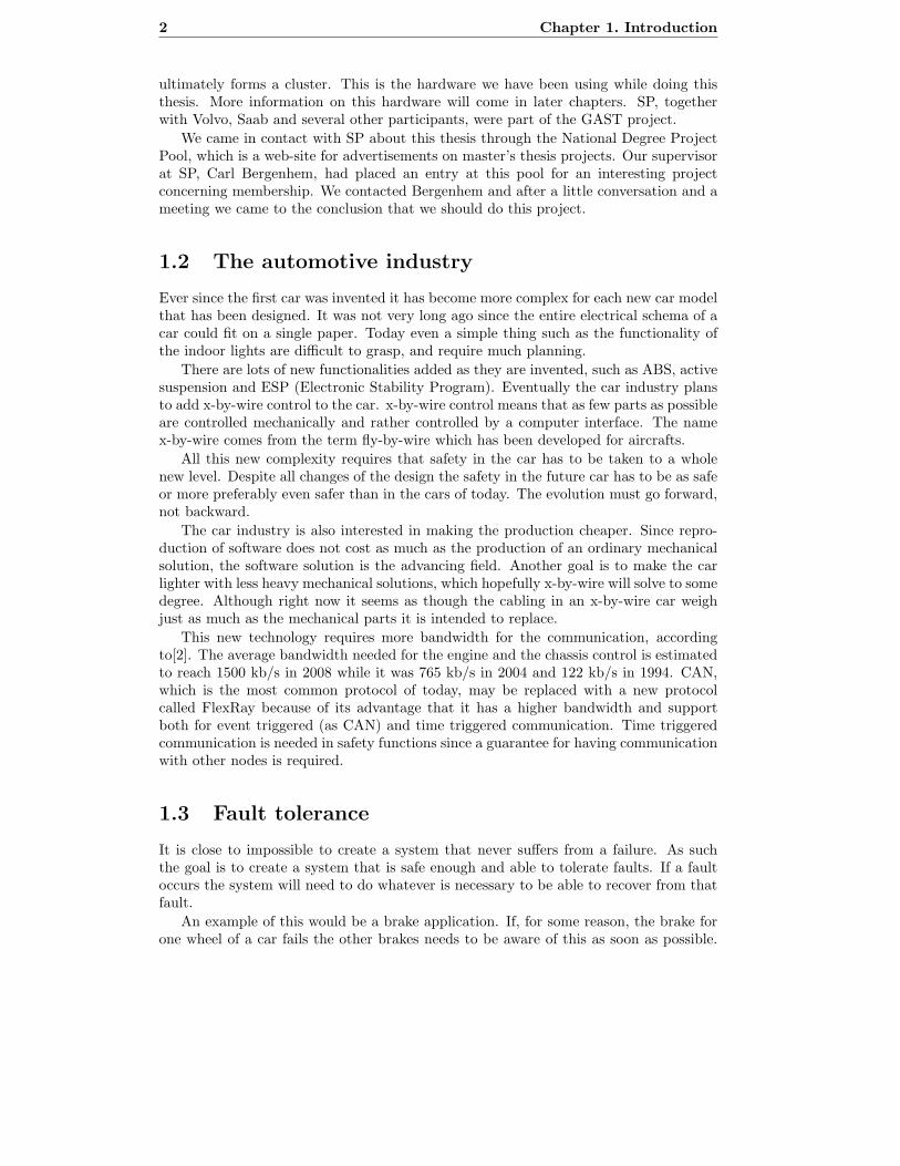
The car industry constantly evolves, and the next step in this evolution is to computarisethe systems in a vehicle that has previously been mechanical. This is however notsomething that is done with the flip of a hand. The major problem with doing thisconcerns safety. A sudden change in how vehicles operate could easily make them muchmore prone to losing its navigation capabilities. That is why there is a great need to domore research on this subject, which is the subject for this master’s thesis project.
1.1 SP Technical Research Institute of Sweden
SP (SP Technical Research Institute of Sweden) is a research institute owned by theSwedish government. It’s main geographical location is Boras, where there are about 850employees working. There are also minor divisions placed in Stockholm and Skelleftea.Boras is where we have been stationed while working on this thesis.
SP’s main tasks are research, technical examinations, measuring, quality assuringand certifications. SP is also obliged to calibrate equipment, such as gasoline pumpsand scales for various uses.
The section of SP where this thesis has been performed, ELp (Electronics and Soft-ware), is the section for research on reliable and safety critical software. They arealso certifying developers for using different standards. There are currently about 10employees working at ELp.
SP is involved in the CEDES (Cost Efficient Dependable Electronics Systems) project,which is a project that researches cost efficient, intelligent safety systems. Among theother collaborators included in the CEDES project, Volvo and Chalmers can be found.Carl Bergenhem, our supervisor at SP, is working in this project with a membershipprotocol which will make the computer systems in a car safer. This is the subject ofthis thesis. The goal is to test the work Bergenhem has done in a real environment tosee how it works and behaves outside a simulator. We hope to have contributed someto the CEDES project by doing this thesis.
A previous project called GAST (General Application Development Boards for SafetyCritical Time Triggered Systems), which had the goal to develop an experimental plat-form for testing of communication and processing in vehicles. The project was closedin may 2006, and resulted in physical hardware that can be used for software testing.The hardware consists of a computing board coupled together with a communicationboard, and each of those pairs is called a node. Several nodes can be connected which
1
2 Chapter 1. Introduction
ultimately forms a cluster. This is the hardware we have been using while doing thisthesis. More information on this hardware will come in later chapters. SP, togetherwith Volvo, Saab and several other participants, were part of the GAST project.
We came in contact with SP about this thesis through the National Degree ProjectPool, which is a web-site for advertisements on master’s thesis projects. Our supervisorat SP, Carl Bergenhem, had placed an entry at this pool for an interesting projectconcerning membership. We contacted Bergenhem and after a little conversation and ameeting we came to the conclusion that we should do this project.
1.2 The automotive industry
Ever since the first car was invented it has become more complex for each new car modelthat has been designed. It was not very long ago since the entire electrical schema of acar could fit on a single paper. Today even a simple thing such as the functionality ofthe indoor lights are difficult to grasp, and require much planning.
There are lots of new functionalities added as they are invented, such as ABS, activesuspension and ESP (Electronic Stability Program). Eventually the car industry plansto add x-by-wire control to the car. x-by-wire control means that as few parts as possibleare controlled mechanically and rather controlled by a computer interface. The namex-by-wire comes from the term fly-by-wire which has been developed for aircrafts.
All this new complexity requires that safety in the car has to be taken to a wholenew level. Despite all changes of the design the safety in the future car has to be as safeor more preferably even safer than in the cars of today. The evolution must go forward,not backward.
The car industry is also interested in making the production cheaper. Since repro-duction of software does not cost as much as the production of an ordinary mechanicalsolution, the software solution is the advancing field. Another goal is to make the carlighter with less heavy mechanical solutions, which hopefully x-by-wire will solve to somedegree. Although right now it seems as though the cabling in an x-by-wire car weighjust as much as the mechanical parts it is intended to replace.
This new technology requires more bandwidth for the communication, accordingto[2]. The average bandwidth needed for the engine and the chassis control is estimatedto reach 1500 kb/s in 2008 while it was 765 kb/s in 2004 and 122 kb/s in 1994. CAN,which is the most common protocol of today, may be replaced with a new protocolcalled FlexRay because of its advantage that it has a higher bandwidth and supportboth for event triggered (as CAN) and time triggered communication. Time triggeredcommunication is needed in safety functions since a guarantee for having communicationwith other nodes is required.
1.3 Fault tolerance
It is close to impossible to create a system that never suffers from a failure. As suchthe goal is to create a system that is safe enough and able to tolerate faults. If a faultoccurs the system will need to do whatever is necessary to be able to recover from thatfault.
An example of this would be a brake application. If, for some reason, the brake forone wheel of a car fails the other brakes needs to be aware of this as soon as possible.
1.4. Membership 3
They may then be able to compensate for the loss of one brake and stop the car almostas safely as with all brakes fully functioning.
Another way to tolerate faults is to use redundancy. It is possible to do manymeasures to be adequately sure that the information arrives where it should.
Redundancy can be implemented on many levels. Information, hardware and soft-ware redundancy are good examples of this.
Information redundancy means that extra information is sent to be sure that thereceiver does not misinterpret that data, e.g. due to disturbance on the channel. Thiscan be done by sending the same data several times, or by using parity bits or checksums.
Hardware redundancy is easily examplified with the computer system of an aircraft.Aircrafts often have three independent computers that all perform the same calculations.The final result from these calculations will be the result calculated by a majority of thecomputer systems. This means that it is possible to have one computer break down andstill have a working system. This method is however very expensive and is therefore notused for personal vehicles.
Software redundancy means that additional software is running on the system thatallow extra precautions if something goes wrong. An example of this is the membershipsystem which is explained in this report. This is preferred since software replication ismuch cheaper than hardware replication.
1.4 Membership
To solve the safety issues that have risen by introducing a new system design, there hasbeen much research done in the computer science field. One of these research areas isto achieve an efficient and reliable membership service.
Membership services have been researched since the late 1970s, and there has beenseveral variants developed since then. What they all have in common is that they allintend to give a consistent view of the correctly working entities in a system.
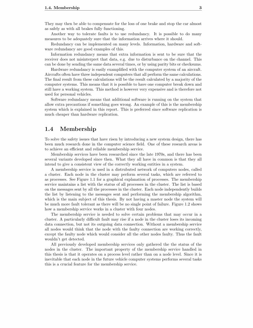
A membership service is used in a distrubuted network of computers nodes, calleda cluster. Each node in the cluster may perform several tasks, which are referred toas processes. See Figure 1.1 for a graphical explanation of processes. The membershipservice maintains a list with the status of all processes in the cluster. The list is basedon the messages sent by all the processes in the cluster. Each node independently buildsthe list by listening to the messages sent and performing the membership algorithm,which is the main subject of this thesis. By not having a master node the system willbe much more fault tolerant as there will be no single point of failure. Figure 1.2 showshow a membership service works in a cluster with four nodes.
The membership service is needed to solve certain problems that may occur in acluster. A particularly difficult fault may rise if a node in the cluster loses its incomingdata connection, but not its outgoing data connection. Without a membership serviceall nodes would think that the node with the faulty connection are working correctly,except the faulty node which would consider all the other nodes faulty. Thus the faultwouldn’t get detected.
All previously developed membership services only gathered the the status of thenodes in the cluster. The important property of the membership service handled inthis thesis is that it operates on a process level rather than on a node level. Since it isinevitable that each node in the future vehicle computer systems performs several tasksthis is a crucial feature for the membership service.

4 Chapter 1. Introduction
A1 B1
E1D1
Node 1
A2C1
D2
Node 2
Figure 1.1: Nodes handles several tasks, each task is called a process. The membershipservice monitors all processes running on all nodes in a cluster. Processes typicallyform groups with processes on other nodes to perform distributed tasks. Process A1 isgrouped with process A2 and process D1 is grouped with process D2 while the otherprocesses (B1, C1 and E1) are ungrouped.
Figure 1.2: The agreed membership when one node has failed. The nodes are representedby the circles and they all are connected to a bus. The bubbles connected to the nodesshows the membership opinion of that particular node, a dysfunctional node got no validopinion and hence considers all nodes to be dead. An ’X’ in a bubble symbolize a deador malfunctioning node, and a ’V’ inside a bubble symbolize a working node.
A membership service can be implemented at either the hardware or software levelof a node. Both have their benefits and problems. A hardware implementation got theadvantage of being faster than an equivalent software implementation, but due to thefast CPUs of today and tomorrow this may not be such a big advantage as it used to be.The big advantage of a software implementation is that is capable of handling processesinstead of only nodes.
The membership service that will be studied and implemented for this thesis isdeveloped by Bergenhem and Karlsson [3]. This membership service is still under devel-opment, and is presented using an iterative approach where there are several versions,each becoming a little more advanced than the previous, so that the reader more easilycan understand how it works. It will be implemented in software for a GAST-clusterwith FlexRay used as communication device. The version of the membership servicethat will be the final implementation is a version that handles multiple processes pernode, and that only view sharing when there has been a change in the system.
1.5. This report 5
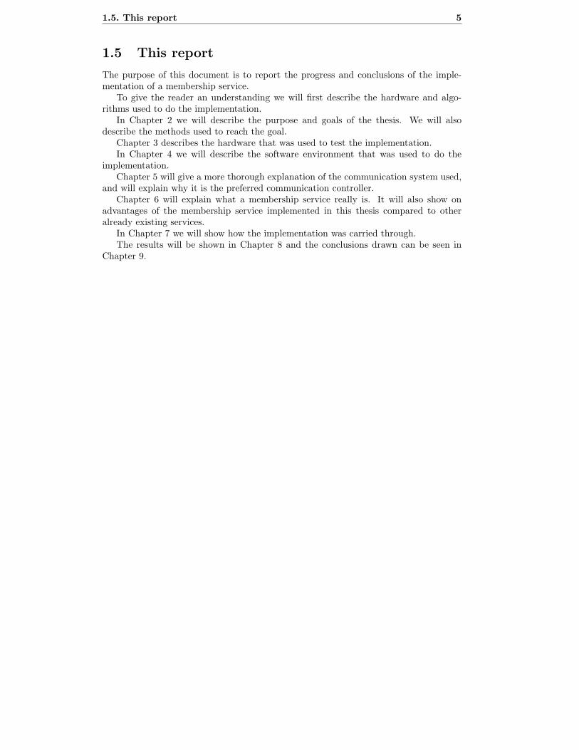
1.5 This report
The purpose of this document is to report the progress and conclusions of the imple-mentation of a membership service.
To give the reader an understanding we will first describe the hardware and algo-rithms used to do the implementation.
In Chapter 2 we will describe the purpose and goals of the thesis. We will alsodescribe the methods used to reach the goal.
Chapter 3 describes the hardware that was used to test the implementation.In Chapter 4 we will describe the software environment that was used to do the
implementation.Chapter 5 will give a more thorough explanation of the communication system used,
and will explain why it is the preferred communication controller.Chapter 6 will explain what a membership service really is. It will also show on
advantages of the membership service implemented in this thesis compared to otheralready existing services.
In Chapter 7 we will show how the implementation was carried through.The results will be shown in Chapter 8 and the conclusions drawn can be seen in
Chapter 9.

6 Chapter 1. Introduction
Chapter 2
Problem Description
As vehicles get more complex and new technologies gets adopted a great amount ofresearch is needed to verify that the new technologies are at least as safe as the previoussystems. New algorithms will be a necessity in these new systems, and it must be proventhat these new algorithms work as specified.
A protocol for a membership service has been proposed by Bergenhem. The task forthis thesis is to test this algorithm on real hardware to see if there are any unexpectedcomplications. The algorithm has previously been tested in a simulated environment,but has never been tested on a physical environment with FlexRay. The thesis will notinclude proving that the algorithm is correct, it will be to verify the functionality of itby testing a limited set of black box test cases.
It will also be needed to measure the performance of the algorithm, in the imple-mentation done for FlexRay.
There are several competing technologies for real-time communication that could beused in vehicles in the future, and hence it will be needed to decide whether FlexRayis the ideal candidate for this, and if this approach to a membership service is the bestway to go.
The last task will be to do a demonstration of the implementation. As the testruns might be quite abstract, one may need quite a bit of insight in the implementationmechanisms to see whether it works or not, so a demonstration will be necessary to beable to show the uninitiated that it works.
2.1 Goals
The main objective for this thesis was very clear already from the start; to implementand test a membership protocol. In addition to the main objective few minor objectiveswere also defined.
The goal setup for this project was:
– Implement the membership protocol with dynamic reintegration for multiple pro-cesses as proposed by Bergenhem[3]. The implementation was to be done usingan iterative approach.
– Test the performance and correctness of the implementation.
– Add support for dual channel usage in the implementation.
7

8 Chapter 2. Problem Description
– Create a demonstration application to show that the membership protocol worksas it should.
2.2 Purpose
The purpose of this project was to show that the membership protocol was correct andshowed off good performance outside a virtual environment on realistic hardware. Themembership implementation would also be a good platform to show an audience withoutknowledge about membership services how it is intended to work without going in toodeep on the protocols characteristics.
This work would also result in a platform for testing and developing so called userprograms. The platform can later on be extended to allow more uses in the future.
2.3 Methods
The tools that will be used for this project are the tools that is part of GEE (GASTEclipse Environment) for development of the node application. The programming lan-guage used to write the node application will be ANSI-C. All the drivers and configu-ration tools are available, so there will be no need to write any assembler code for thenode application.
To develop the test environment Java 1.6 will be used, all the Java source code willbe written in Eclipse.
To allow both members of the project to work on the same code simultaneously,Subversion, which is a version control system, will be used.
The node application will be written using an iterative approach. The developmentcycle will follow the membership algorithms iterations, but will take an additional iter-ation to be able to handle multiple processes, which is not handled in the final versionof the algorithm.
The tools needed will be updated as the project moves along, as it is hard to predictall the features we may want to have for the final test platform.
2.4 Related Work
There are a number of theses written that has handled the same subject as this thesis.The most related thesis has been performed by Bergstrom and Hogberg[4], which alsois the thesis that we have continued upon in this project.
The thesis project done by Vorkapic and Myhrman[18] has resulted in the driversfor FlexRay which we have used, and also provided us with an easy to use FlexRayconfigurator.
Chapter 3
Hardware
The hardware used in this project derives from a project called GAST (General Ap-plication Development Boards for Safety Critical Time-Triggered Systems). To developthe software and supply the nodes with runnable binaries ordinary PC:s are used. Tosimplify the communication between a GAST cluster and a PC, a PC with severalRS232-ports are used for that communication.
3.1 GAST hardware
The boards from the GAST project support four communication controllers that are in-teresting for the car-industry. The controllers are CAN, FlexRay, TTCAN and TTP/C.The GAST project has also developed two different types of ECU (Electronic ControlUnit) boards (G1 and G2) to run simulations on. All the GAST hardware are of OpenSource hardware design and has basic software drivers for research and development.
The hardware parts from the GAST project used in this project are G2 boards (seeFigure 3.2) and FlexRay boards (see Figure 3.3).
In our cluster one G2 board and one FlexRay board connected to each other viaa passive backplane forms one node, our cluster consists of five nodes. All nodes areconnected via FlexRay. The physical layer used by the FlexRay boards are RS485.
3.1.1 G2
The G2 board consists of two CPUs, one MPC565 and one MC9S12DG256B1 Freescalemicrocontroller [7]. These two microcontrollers can control each other, the MPC canforce the HCS12 into RESET and the HCS12 can give the MPC565 a non-maskableinterrupt.
The communication between the PC and the G2 board is done over RS232. Thesoftware is uploaded over RS232 to the MPC565. It is also possible to do some debuggingover the RS232 connection, by using the built in debugger. The software is compiledwith a version of GCC that has support for compiling to the MPC565 chip.
The debugger on the G2 card is called G2DBG. It serves not only purpose as adebugger, it can also function as a bootloader on the card. The final version of thisdebugger has some limitations, one of those is that it handles all the exceptions in the
1Further on referred to as HCS12.
9
10 Chapter 3. Hardware
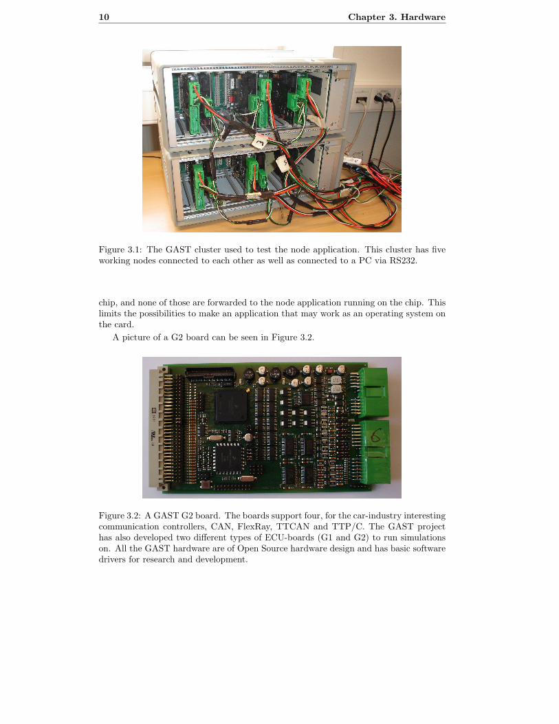
Figure 3.1: The GAST cluster used to test the node application. This cluster has fiveworking nodes connected to each other as well as connected to a PC via RS232.
chip, and none of those are forwarded to the node application running on the chip. Thislimits the possibilities to make an application that may work as an operating system onthe card.
A picture of a G2 board can be seen in Figure 3.2.
Figure 3.2: A GAST G2 board. The boards support four, for the car-industry interestingcommunication controllers, CAN, FlexRay, TTCAN and TTP/C. The GAST projecthas also developed two different types of ECU-boards (G1 and G2) to run simulationson. All the GAST hardware are of Open Source hardware design and has basic softwaredrivers for research and development.

3.1. GAST hardware 11
3.1.2 FlexRay
The FlexRay board has a Freescale MFR4200 chip and double RS485 transceivers, onefor channel A and one for channel B, in FlexRay. The G2 board and the FlexRay cardcommunicates via a passive backplane. The G2 board needs a 12 VDC power supplyto operate, and the FlexRay board receives its power supply from the G2 board via thebackplane. It is possible to connect several FlexRay boards to one G2 board to get morethan one link.
A picture of a FlexRay board can be seen in Figure 3.3.
Figure 3.3: A GAST FlexRay RTcomm board.
3.1.3 Backplane
The backplane for a GAST node is of the passive type, which means that it does notcontains any electronics. The purpose is just to make the connection of two, or moreGAST boards easier. Further reading about for example what signals the pins corre-spond to can be done in the G2 Board Manual [8]. Figure 3.4 show what the backplanelooks like.
Figure 3.4: The backplane allows the G2 board and the FlexRay board to communicatewith each other.

12 Chapter 3. Hardware
3.1.4 GAST BDM adapter
The GAST BDM adapter is a device used to update the software for the HCS12 controlleron the G2 board. The BDM adapter is connected to the G2 board using a 6 pole flatcable, and then by a DSUB-9 female connector, using the standard RS232 protocol, toa PC. By using a specific piece of software called BDM12, the software for the HCS12controller can be updated.
The BDM adapter was only used once throughout the project. A bug was found inthe debugger/bootloader software for the HCS12 connector. The bug was not makingthe board unusable, but it was best to fix it so no problem would occur in the future.
The BDM adapter is shown in Figure 3.5.
Figure 3.5: The GAST BDM hardware adapter used to update the software for theHCS12 controller.
3.2 Hardware setup
The first step to get this project running was to install the GAST-cluster. As previousthesis workers had already used the same cluster it was assumed that it was as goodas ready. Since it responded as it should have it appeared that it was working fine.However after more than a week of testing on the cluster with no success, there weresuspicions that there was something wrong with most of the nodes in the cluster.
At that time it was uncertain whether it was the software or the hardware that wasmalfunctioning. A simple test program was received (that had been tested on anotherGAST-cluster and was working on that) from Svenningsson and Chaudry who wrote[13]. The program was a simple ”Hello World”-application. After trying that programon the cluster it was obvious that the hardware was broken or had a bad setup.
The following week a great amount of error searching on the G2 and FlexRay boardswas performed. A few suspicious signals was found, e.g. a disable signal from the G2board going to the FlexRay board showed a high-frequency wave signal, while it shouldhave been a constant high signal to not disable the communication controller.
After much work on this problem but no solution found a meeting was arrangedwith an expert on the subject, Roger Johansson, whom has written [7]. A few tests on

3.2. Hardware setup 13
the GAST-cluster was done by Johansson, and he concluded that most of the FlexRayboards were broken. The broken boards was replaced and the GAST-cluster was finallyworking.

14 Chapter 3. Hardware
Chapter 4
Software
To develop software for the GAST nodes it is of great convenience to have the righttools to ease the process. Many tools are already available, and those will be introducedin this chapter.
4.1 GAST Eclipse Environment
GEE (GAST Eclipse Environment) is a package containing several tools used to developsoftware for the GAST hardware. It contains Eclipse, GAST plug-in for Eclipse, Cygwinand a GCC compiler with support for the MPC565 architecture. In this thesis GEE hasbeen used to develop all the software for the GAST cluster. The following sections willdescribe the tools included in GEE more thoroughly.
4.1.1 Eclipse
Eclipse [1] is an IDE (Integrated Development Environment) written in Java. It isprimarily designed for writing Java code, but has plug-ins to support C, C++ andseveral other programming languages.
GEE contains a plug-in to upload files to GAST-nodes via Eclipse. This plug-in washowever very slow and inconvenient to use, thus it was decided not to use this plug-in.
4.1.2 Cygwin
Cygwin [5] is a Linux like environment for Windows, it provides all the most necessaryLinux commands in Windows. This made some tedious work much easier by giving amore powerful environment for creating scripts to automate repetitive tasks and creatingMake-files.
4.1.3 GCC
GCC (GNU Compiler Collection) [14] is the compiler used to create the executablebinaries for the MPC565 processor on the G2 card. GCC has been used together withMake-files to create the files usable on the G2 card.
GCC creates S19-files from the ANSI-C source code. S19-files are the binary fileformat accepted by the MPC565 architecture.
15
16 Chapter 4. Software
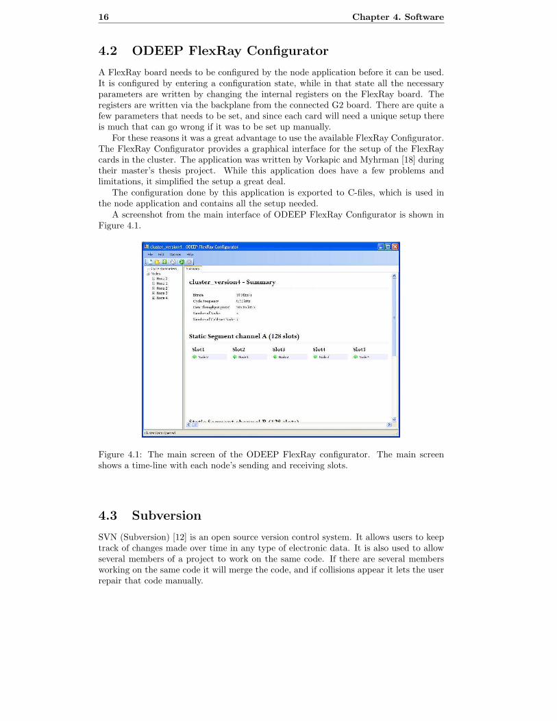
4.2 ODEEP FlexRay Configurator
A FlexRay board needs to be configured by the node application before it can be used.It is configured by entering a configuration state, while in that state all the necessaryparameters are written by changing the internal registers on the FlexRay board. Theregisters are written via the backplane from the connected G2 board. There are quite afew parameters that needs to be set, and since each card will need a unique setup thereis much that can go wrong if it was to be set up manually.
For these reasons it was a great advantage to use the available FlexRay Configurator.The FlexRay Configurator provides a graphical interface for the setup of the FlexRaycards in the cluster. The application was written by Vorkapic and Myhrman [18] duringtheir master’s thesis project. While this application does have a few problems andlimitations, it simplified the setup a great deal.
The configuration done by this application is exported to C-files, which is used inthe node application and contains all the setup needed.
A screenshot from the main interface of ODEEP FlexRay Configurator is shown inFigure 4.1.
Figure 4.1: The main screen of the ODEEP FlexRay configurator. The main screenshows a time-line with each node’s sending and receiving slots.
4.3 Subversion
SVN (Subversion) [12] is an open source version control system. It allows users to keeptrack of changes made over time in any type of electronic data. It is also used to allowseveral members of a project to work on the same code. If there are several membersworking on the same code it will merge the code, and if collisions appear it lets the userrepair that code manually.

4.3. Subversion 17
SVN is written with the intention to replace CVS (Concurrency Version System).SVN has grown quite popular, and has now surpassed CVS in Open Source projects.
Since Eclipse was used as the development environment it came in handy to use theplug-in to Eclipse called Subclipse [11]. This plug-in provided all the functionality givenby Subversion integrated in the Eclipse environment.

18 Chapter 4. Software
Chapter 5
The FlexRay communicationsystem
FlexRay is a communication system for advanced automotive control applications. It isthe result of a cooperation between a couple of car manufacturers and some electronicsmanufacturers. To organize the work they started the FlexRay Consortium in September2000, the original members were BMW, Daimler-Chrysler, Philips and Motorola. Sincethen the Consortium has grown to include some of the automotive industry’s largestand most influential players, including Bosch, General Motors, and VW among others[15].
5.1 Description of FlexRay
FlexRay is a time-triggered architecture with support for event-triggered communica-tion. FlexRay has support for dual channels which gives higher fault-tolerance and/orincreased bandwidth. The maximum bandwidth in a FlexRay network is 10 Mbit/s.FlexRay supports two different kinds of cluster configuration, a bus network or a starnetwork. These two network types can be combined or used separately over one or twochannels [16].
The FlexRay communication protocol has all the benefits of a time-triggered com-munication protocol such as the built-in knowledge of when an alive node is supposedto transmit. In addition to this it also has support for a collision-free bus access andguaranteed message latency. There are also an independent bus guardian that providesfurther support for error containment.
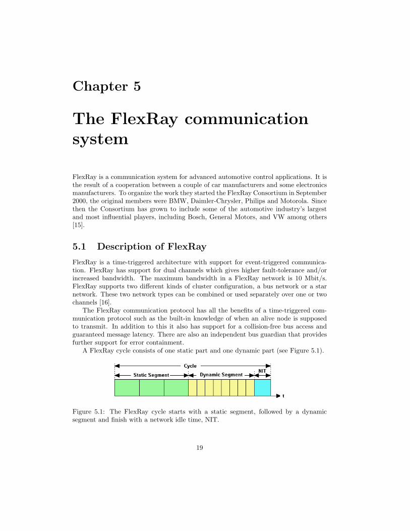
A FlexRay cycle consists of one static part and one dynamic part (see Figure 5.1).
Figure 5.1: The FlexRay cycle starts with a static segment, followed by a dynamicsegment and finish with a network idle time, NIT.
19

20 Chapter 5. The FlexRay communication system
The static segment consist of a configurable number of slots, each slot containingroom for the same amount of data. Every message is broadcasted to every other nodein the network. If one or more nodes has a greater need for communication that nodecan be assigned to several slots which gives it a larger static piece of communication.It is also possible for a node to only listen to a channel by not being assigned to anyslot at all. The slots that are not assigned to any node and the slots assigned to brokennodes will be silent.
The dynamic segment consists of mini-slots. Each mini-slot will be extended to afull-size dynamic slot when the node assigned to the current mini-slot has a message totransmit. Like the static segment each mini-slot is assigned to one node. The first slotis the one with the highest priority since it is the first to be able to expand to a full-sizeslot. It is not possible for all mini-slots to expand to a full-size slot, the result of this isthat the dynamic messages with the lowest priority can suffer from starvation.
Network idle time, NIT, is the time in the end of each cycle. This phase is used forsynchronization of the timing in the protocol. The time in a FlexRay cycle is measuredin macro-ticks, mT. Each mT consists of number of micro-ticks, µT, which is the smallesttime unit in FlexRay. One mT into the NIT segment a recalculation of how many µTthere are in one mT starts. This is done every cycle, locally at each node.
The division between static messages and dynamic messages is configurable anddepending on the network requirements it is possible to make them larger or smallercompared to each other.
A slot contains a frame that consists of a header segment, a payload segment anda trailer segment (see Figure 5.2). The header segment consist of information aboutthe frame, such as the payload length, cycle count and different indicators. The headersegment also has a field for a cyclic redundancy check (CRC) to keep track of that theheader does not contains any errors. The field ’payload length’ contains informationabout the size of the payload segment. The payload segment contains the data trans-mitted by the current node and the last segment, ’trailer segment’ contains a CRC overthe whole package.
Figure 5.2: A FlexRay frame looks the same way if it is in the static or the dynamicsegment.
As an extra precaution a node can only join one channel at a time. This is becausea failing node must not be able to disturb the whole network. It is also possible to makea node a start up node or not. Only the start up nodes are allowed to try to initiatecommunication which reduces the chance of a failing node to disturb.
5.2. MFR4200 21
5.2 MFR4200
Freescale semiconductor manufacture and sells FlexRay communication controllers, oneexample is the MFR4200. The implementation in a MFR4200 chip follows the FlexRayprotocol specification.
During normal operation the MFR4200 is in a state called ’Normal active Opera-tion’. All states are represented by a number, ’normal operation’ is number two. TheMFR4200-chip stores this state in a buffer that can be read by the CPU connected tothe MFR4200-chip.
The startup procedure starts when two or more modules are connected to each otherand at least one of them is a startup node. When a node is powered up it enters astate called ’configuration’ state. In this state a startup node may make a configurablenumber of attempts to start up the communication, if this fails the node will fall backinto the ’integration listen’ state. To make a new series of attempts the node needs tore-enter the ’configuration’ state.
The communication of FlexRay is based on a time-triggered design, it means thatthe physical channel is divided into time segments for each node to transmit in. Thetimetable is defined before startup and distributed to all nodes. To make all nodes worktogether and know when a certain node is allowed to transmit all the nodes has to besynchronized.
To Synchronize messages in a higher layer the MFR4200 provides a cycle counterthat counts the cycle up to 63. This counter can be read and compared to the counterin the header segment of each FlexRay frame (see Figure 5.2).
5.3 Comparison of FlexRay, CAN and TTP/C
A time-triggered communication protocol has the benefit that it is foreseeable when acertain node is allowed access to the channel. A disadvantage due to this is that if a noderequires less bandwidth for a period of time the bandwidth assigned to that node go towaste, hence a event-based communication protocol can be preferred. In a event-basedprotocol the access to the channel is triggered by an event at a node and if channel isidle the message is sent right away. If the channel is not idle there are different ways todecide for how long to wait and whos turn it is to use the channel next. The decitioncan be made based on an taking turn or an priority algorithm all depending on whatrequirements there are on the protocol.
5.3.1 TTP/C
Time Triggered Protocol (class C), TTP/C, is a example of a time-triggered commu-nication protocol. TTP/C uses Time Division Multiple Access, TDMA, to access thephysical channel. This means that the channel is divided into timeslots for each node totransmit in. TTP/C has a built in system for supervision of which node are members inthe cluster at a certain time. The bus has, simular to FlexRay, a way of synchronisingthe opinion of the current time. TTP/C is a newly developed protocol with support formany different types of physical layer. The highest bandwidth that can be achieved is25 Mbit/s.

22 Chapter 5. The FlexRay communication system
5.3.2 CAN
Controller Area Network, CAN, is a event-triggered communication protocol. CAN wasdeveloped in 1980 by Robert Bosch GmbH for the automobile industry to connect theECU in a vehicle. CAN uses a priority algorithm to decide which node to gain access tothe channel first. After a message has been transmited all nodes that want to transmitsends a unique binary code onto the channel. During the low signal every node listenfor an other node, if there are an other node transmiting that node has a higher priority(see Figure 5.3) and the node with low signal terminate its transmition.
Figure 5.3: The node with the highest binary code wins since the most significant bit issent first.
Depending on what type of physical layer that is used different bandwidth is achieved.The higest possible is 1 Mbit/s.
5.3.3 Requirments and comparison
In a safety critical real time distributed application the communication between all nodesis very important. It is also important to have sufficient bandwidth for all time criticalmessages not to be delayed through communication. The application communicationover the network also needs to know if the node that the message is concerning is upand running, to be able to compensate for an malfunction node.
To make sure that a message will not be delayed more than a certian time a time-triggered communication like TTP/C can be used. An other solution is an event-triggered environment like CAN. This however can only be used if the requirementto be able to guarantee that a message should be delivered at a certain time can beignored because CAN is a priority based communication. This requirement can notignored in a safety critical application.
The benefit of CAN over FlexRay are that it is widely used and the components arewell known and mass produced. Because of the safety requirement and the prognosisthat the need of bandwidth will increase[9], CAN is no longer sufficient (see Figure 5.4).
The use of only time-triggered such as TTP/C is an good alternative for safety criticalapplications but since FlexRay has support for both time-triggered and event-triggeredcommunication car manufacturers may be more interested in a communication systemthat can be used for all different applications in a vehicle.
FlexRay does not have a membership service built in like TTP/C has. This meansthat if there are a requirement for such a service, that service has to be implementedin software instead of a hardware solution like TTP/C. The membership service inTTP/C only monitors nodes, but when implementing a service in FlexRay one canchoose an algorithm similar to the one presented in this thesis, written by Bergenhem,that supports monitoring of processes.

5.4. FlexRay configuration 23
Figure 5.4: From left to right, CAN 1 Mbit/s, FlexRay 10 Mbit/s and TTP 25 Mbit/s.
5.4 FlexRay configuration
A limitation for the posting of static messages is that the transmitted frame needs tobe written down and committed in the transmit buffer one slot and 4 mT before thecurrent slot that the transmission is supposed to be done in. That would be in the endof slot n+3 in Figure 5.5.
Since G2 boards in the GAST environment handles all the exceptions without sup-plying them to the executable programs the solution has to poll for events in the com-munication.
Figure 5.5: The messages transmited from Node 1 Proc 1 will not be available for theother nodes in the cluster until sometime in slot n+1. However, since all tha actual workis done in the beginning of each slot there is no guarantee that the message has arrived,therefore it is necessary to wait until slot n+2 to be sure of received that message. Inthis slot, n+2, it is possible to do calculations on the received data from slot n. Afterthe calculation is done the next slot, slot n+3 is used for writing down to the transmitbuffer.
24 Chapter 5. The FlexRay communication system
It would be possible to have just two slots in between but that would require ainterupt when the data from slot n is available and directly after that writ down thenext message. With three slot in between it is possible to write down to the transmitbuffer in the end of slot n+2, in other words, merging slot n+2 and slot n+3.
The end of all slots is needed to poll for the next slot. To be sure of that no criticalmoment is missed the NIT and the in-between slots time was configured long, almostexaggerated. This made the use of the bandwidth very poor but this was not the mainthing to test.
5.5 FlexRay today
Today FlexRay is used in BMW X5 as a testplatform to gain experience with FlexRay.FlexRay handles the communication between the suspension in the car to make themwork together to make a comfortable ride. It is not as safety critical as steer-by-wireapplication but it can result in strange driving characteristics if the communication fails.To use FlexRay in more safety critical applications, such as brake-by-wire, it needs touse both channels and perhaps two different power supplies. The batteries that are usedtoday makes the benefit of weight saving disappear if the new system is compared to abraking system of today.
5.6 FlexRay in the future
FlexRay is a comparatively new communication system for the car industry. Theprospect of success for FlexRay are good since there are several large car manufac-turers that have invested time and money into this project. The FlexRay Consortiumhas also members from the electronics manufacturers which gives the project someonewho’s interests is to make a market for the hardware.
Chapter 6
Group membership services
A group membership service is an important abstraction for the next generation of com-munication systems. To support safety-critical applications for real-time environmentsit is necessary to be able to reliably tell which of the other entities in a cluster areworking as they should, where each entity is either a node or, as in this case, a processrunning on a node.
Redundancy management is used to tolerate hardware failures during operation ofthe system. Hardware failures are nearly impossible to avoid, and thus it is importantto design the system in such a way that it tolerates faults.
Grunsteidl [6] defines redundancy management as consisting of three services:
– A timely and dependable communication service.
– A membership service that provides each component with consistent and timelyinformation about the operational state of the other components.
– A reconfiguration service that allows to remove faulty components from the systemand to re-integrate components into the system.
The first service is a prerequisite of any distributed real-time system. The other twoare needed for redundancy management while being useful as a basis for other services,too. A redundancy management service should not degrade the real-time communicationservice provided by the distributed architecture. The redundancy management servicemust be fault tolerant and it must possess real-time capabilities. For a membershipservice to be usable in a real-time system, it has to fulfill two requirements; it mustbe consistent and timely. Consistency means that all correct nodes have the samemembership information. Timely membership information refers to the property ofthe membership protocol that any state change of a communication node from active toinactive (or vice-versa) at time T−∆ is known to all other nodes at time T . Furthermorea node should be able to know about its own state at time T if it did not fail or shutdown [10].
There are already many existing protocols for a membership service in use today.Most notable of those is the membership service included in TTP/C. The membershipservice in TTP/C is implemented in the communication controller, and maintains themembership agreement by regularly sending the membership information to each nodein the system. Most membership protocols available today does in fact use this method.It is however obviously not the most efficient way to keep a consistent view across all
25

26 Chapter 6. Group membership services
nodes. A common restriction in most available protocols, including TTP/C, is that theyonly allow a very strict amount of node failures in a given time division.
The protocol that is studied and implemented in this thesis is developed by CarlBergenhem and Johan Karlsson [3]. Bergenhem and Karlsson’s proposed protocol isin turn based on a protocol described by Velerio Rosset et al in [17]. The protocoldeveloped by Rosset et al. only have support for nodes. The major contribution fromBergenhem and Karlsson is the added support for processes which is a very importantfeature.
The proposed protocol is, in contrast to TTP/C, separate from the communicationcontroller.
6.1 Enhancing safety in a distributed environment
There are many distributed services that are required in the computer system of avehicle. Braking, stability control and collision mitigation are a few examples. All ofthese requires a consistent view of which nodes and processes in the system that arefunctional. This can obviously be implemented as a separate service in each of theseapplications. However, to keep the security to a maximum it is much more preferred toimplement a shared service, hence the membership service. All additional programmingin an application to handle these things is unnecessary and may be faulty implemented.
As the communication systems used in vehicles today mostly facilitate event-triggeredbuses they are unable or very bad at detecting faulty nodes. Since it is not possible toknow whether a package is lost or if the nodes didn’t intend to send a package whenusing a pure event-triggered communication system, one may never find out if a node isbroken. It is however possible to add a time-triggered layer on top of the existing, andachieve a time-triggered system from a previously event-triggered. This has been donefor many existing event-triggered systems, such as TCP and CAN. A time-triggeredprotocol is needed to implement a reliable membership service.
6.2 Proposed algorithm
The algorithm proposed for the membership protocol by Bergenhem and Karlsson canbe found in Appendix H.3. An explanation of when the different phases are performedis shown in Figure 6.1.
The algorithm is executed once each cycle. Although, which can be seen in thealgorithm description, the membership decision phases will only be executed if a changehas been detected on any correct node in the system. The algorithm can handle thatup to half (not including) the nodes fails every 2 consecutive cycles.
Bergenhem and Karlsson’s protocol has not been formally verified as this is written.So an advantage of the membership service available in the TTP/C protocol is thatthere is a documented proof that the protocol is working correctly.
6.2.1 The heartbeat
The heartbeat is a flag sent together with the static message that signifies correctness.The phase in which the static data is sent and received is called the FD-phase (FailureDetection-phase). Each process that wants to be part of the membership group mustsend the static message each cycle with the heartbeat flag set. The heartbeat flag
6.2. Proposed algorithm 27
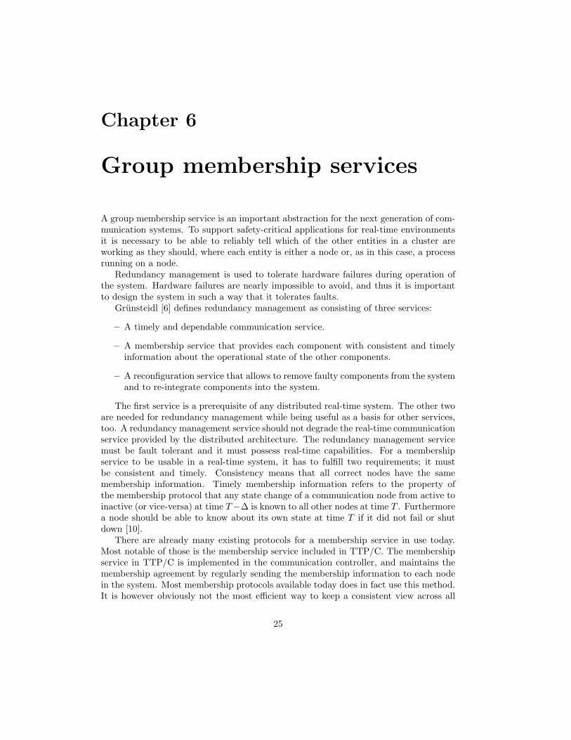
Figure 6.1: Illustration of a FlexRay cycle showing the segments and which membershipphases that corresponds to the segments.
consists of one bit at the end of the message. The rest of the message contains alladditional static data the process wish to send to other processes in the system, calledthe payload.
While receiving the static data a local opinion of which processes are working iscalculated. The local opinion is a set, and may yet differ from the opinion on the othernodes.
opinion′′ = {receivedheartbeats}
When all heartbeats have been received the opinion is updated again. It is intersectedwith the current membership view. This eliminates all the processes which may not bepresent in the current membership view. A specific procedure needs to be taken to jointhe membership.
opinion′ = opinion′′ ∩ membershipview
In addition to the heartbeat flag there are two more flags in the static message. Thesecond is the join flag. This flag is set when a process wants to join the membershipview after having been excluded for some reason. The opinion is updated to include allthe processes that wishes to join. The join flag is not available in the most basic versionof the membership protocol, where it is not possible to have excluded nodes to join themembership.
opinion = opinion′ ∪ joiningprocesses
The third flag is the membership request flag. Any node that experiences a changein the system (e.g. a node that has suffered from a failure) also sets this flag in the staticmessage. This will tell all nodes to perform the MC-phase (Membership Communication-phase) and the MD-phase (Membership Decision-phase). This flag is only used in themembership protocol with dynamic operation. Opinion is the candidate membershipview. If it doesn’t match the current membership view the membership request flag willbe set.
Setting the membership request flag on a detected change will solve the problem withan ILF (incoming link failure, further explained in Chapter 7.1.3). As this will triggerthe membership communication and decision phase, the decision function will detectthat the node is faulty (the node won’t get the membership communication messagesand will therefore be excluded from the membership).
A node that joins the membership is not expected to have any knowledge about thecurrent membership. It will assume the default values, that all nodes are alive. Thisview will not be counted as a vote during the membership decision phase. The real viewwill be found at the end of the cycle it sent its join message in.

28 Chapter 6. Group membership services
6.2.2 Sharing opinion
In the very basic version of the algorithm the opinion calculated in the FD-phase isshared in every cycle. The phase in which the opinion is shared with all nodes is calledthe MC-phase. This provides an unnecessary amount of data to be sent every cycle.In the later versions of the protocol the MC- and MD-phase is only performed when achange has been recorded anywhere in the system. The news of a change in the systemis transferred using the membership request flag.
When sending the opinion the dynamic segment is used. To be completely sure thatthe message is transmitted it is needed to give the message highest priority. If it doesn’thave the highest priority the other dynamic messages might fill the dynamic segment,not allowing the opinion to be sent.
The message sent in the MC-phase consists of the opinion calculated in the FD-phase,the size of the number of members in the opinion and finally the gen-id (Generation-ID).
After the MC-phase has been performed the MD-phase (Membership Decision-phase)will be performed. This phase is just as the MC-phase only performed when a changein the system has been found.
The gen-id is a number which is incremented each time a change occurs. During theMC-phase all gen-ids received is stored in the GEN-ID-vector. The gen-id is used toexclude faulty members from the membership by removing all members which doesn’thave gen− id = max(GEN − ID). The gen-id will always be the highest for non-faultynodes.
During the MD-phase strict majority voting will be used to determine the new mem-bership view. The opinion that is calculated on more than half of the correctly workingnodes will be the new membership view. Nodes have to be in the membership view fortheir vote to count. This prevents subsets of the system to create small isolated systemswith their own membership.
6.2.3 Strict majority voting
The decision function’s purpose is to let all nodes in the system have the same view. Inthe proposed algorithm the decision function is implemented with strict majority voting.This means that a candidate membership view needs to have at least half of the nodesvoting for it. In case of a draw the result will be undefined, which leads to that nodebeing excluded from the membership.
The algorithm for the decision function can be found in Appendix H.1.
6.2.4 Consensus
With the agreement calculated in the MD-phase consensus will always be reached withintwo cycles from when the fault was found, which easily can be shown informally. If thefault is found in the FD-phase by a correct node that has not yet sent its heartbeatconsensus will be reached by the end of the same cycle.
As mentioned before this applies as long as the number of failures in two consecutivecycles are less than half of the currently correct nodes (which also are members of thecurrent membership view).

6.3. Robustness 29
6.3 Robustness
Much of this protocol relies on that nodes do not send any information when it hassuffered from a failure. This is called the babbling idiot problem. A node that sendsmessages even while it has failed may erroneously be included in the membership whenit shouldn’t. This is solved by letting the node monitor itself, using a bus-guardian. Abus-guardian is a separate chip that monitors the communication controller and preventsit from behaving badly.
An aspect that may be important to look at is what a correct node that have lostits communication abilities with the rest of the system should do. While some systemsshould not do anything at all since they may affect the rest of the system very negatively,there are certainly less important systems that still may be able to do its job. This ishowever completely up to the developer of the processes, running on the nodes, to decide.
6.4 Minimizing communication overhead
The combination of the static/dynamic usage is what gives this protocol a very smalloverhead. The overhead during normal usage should be only 3 bits/process each cycle.This also makes this protocol a good choice even for larger systems where there are manyprocesses. It scales well on a process level. The overhead when fault occurs in eachcycle would be the size of the MC-message for each node. The size of the MC-messagedepends on the implementation, see Chapter 8.3.1 for a calculation of the overhead ofthe implementation done during this project. Since 64 nodes is the maximum possibledue to restrictions in the FlexRay protocol, and much fewer nodes would be expectedin a real system, this does not seem to be any problem.
6.5 Improving the protocol
There are many improvements that are possible to do in the membership protocol.Bergenhem is currently working on a protocol where the other nodes may see what typeof fault that has occurred on a process or node.
The fault can be of such simple character as a CRC fault. A CRC fault could havebeen the cause of disturbances in the environment.
A CRC fault could be specifically handled. Since it is not unrealistic that such faultsoccur in some environments it would be a good idea to resend that message instead ofexcluding the process completely from the membership.
A threshold can be set on how many attempts of sending a process can do. Differentprocesses should however have different values for the threshold. A brake process doesof course need a smaller threshold than a system of window openers.

30 Chapter 6. Group membership services

Chapter 7
Implementation
This chapter will describe the details of how the membership protocol was implemented.It will also describe the helper software and explain how and why the helper softwarewas developed.
7.1 Node application
The node application is the software running on the GAST G2 nodes. The node ap-plication contains a rudimentary RTOS (Real-time Operating System), a membershipservice, and a few demonstration user applications. The node application is in the S19file format, which is the Motorola PowerPC format of executable files. The debuggeravailable on the G2 board is used to upload and run the node application.
7.1.1 Membership algorithm implementation
The development process of this thesis did not follow the original plans. The firstintention was to continue on the previous thesis done by Bergstrom and Hogberg [4].After some studying of the code from that thesis it was apparent that the code was notcomplete. After reading their report yet another time it was also quite clear why theywere not able to finish it. The same hardware problem we had ran in to had struckthem at the end of their project, but wasn’t solved.
After a couple of days of trying to fix their code with no success we took the decisionto implement it our selves from the very beginning. The previous code was still veryuseful. We took much inspiration from earlier theses, which also contained useful codefor the simple things such as math functions, input/output functions and ideas of howto control the operating system without the use of interrupts.
Just as the protocol was explained we implemented it using an iterative approach,starting from a simple version and working up to the final version. However, for practicalreasons the very first iteration of the protocol was not implemented. The first iteration ofthe protocol do not differ much from the second iteration in aspect of an implementation,hence the second iteration protocol became the first iteration of the implementation.
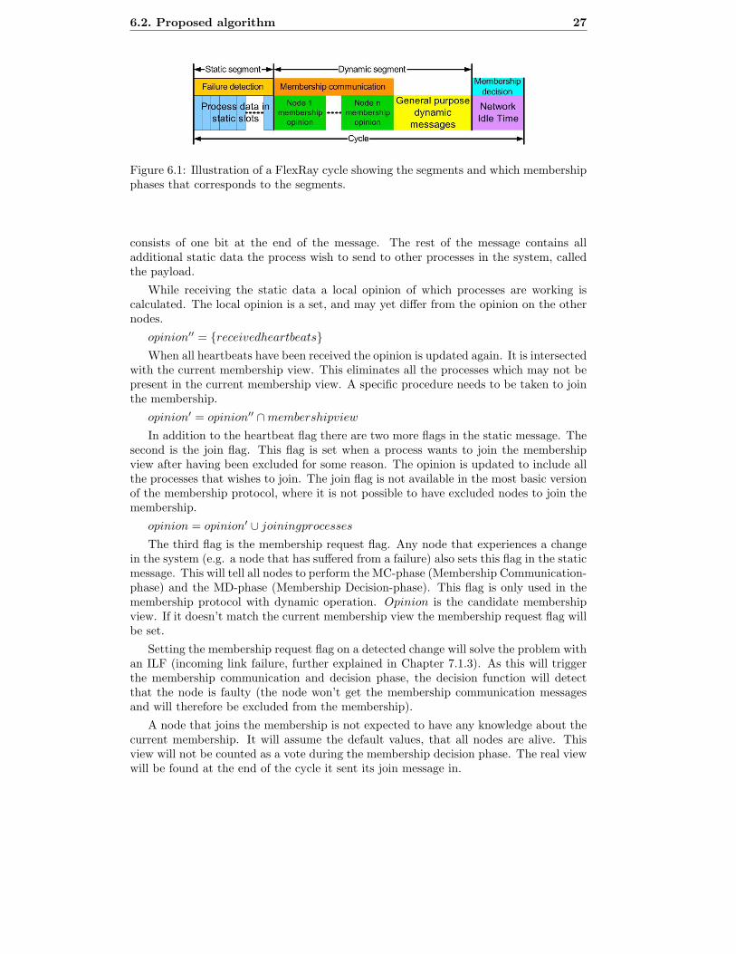
A graphical overview of the features in each iteration is found in Figure 7.1.
31
32 Chapter 7. Implementation
Figure 7.1: Illustration of the iterative development of the node application.
Membership Reintegration Version — first iteration
The first version of the membership implementation follows the second iteration of thealgorithm, see Appendix H.2 for an algorithm description. This versions has support forthe basic membership operations, including functionality to reintegrate excluded nodes.
This implementation only allowed for four nodes to participate. This restrictionwas caused by hard-coded data structures. As there was no possibility to use dynamicmemory on the node all data structures had to be initiated when the program started.
The fault injection in this version was very basic. Fault injection is the action ofartificially introducing faults into the nodes or processes, it is more thorougly describedin Chapter 7.1.3. It only allowed faults to be injected on a cycle level. This made testruns of the membership algorithm correctness pointless, since it was not possible to testvery many scenarios.
The implementation of this version gave us a great understanding of how to workwith the GAST cluster, and this knowledge was of great importance in the later versions.
Membership Dynamic Version — second iteration
In the first version all the opinions of which nodes were alive was sent in every cycle.The dynamic version changed that so the necessary data was only sent when a changewas detected. This reduced the bandwidth used by the membership protocol. TheFlexRay configuration was updated to support this. The opinion data was sent usingthe dynamic segment of the FlexRay cycle, while 3 bits of the static data was used tosend a heartbeat every cycle along with a detection bit which was set when a change inthe cluster was detected.
Additional improvements on the implementation was also made. It was now possibleto run the cluster with 3 or more nodes by only changing a constant variable in thecode. Although, due to the development environment used the FlexRay configurationhad to be updated if the number of nodes was changed.
In this version the fault injection was updated. It was now possible to inject faults
7.1. Node application 33
on a phase basis. The faults could be injected in either the failure detection phase or themembership communication phase. Since this still was not enough to be able to run thefinal tests, no conclusion on whether the algorithm worked correctly or not was drawn.
Membership Final Version — final iteration
The final version added several big changes to the implementation. The most importantchange in this version was the ability to specify multiple processes running on each node.Each process, called a user program, sends its own heartbeat together with the data itwishes to send. The membership decision phase is done on the node level, so this ishandled by the underlying system.
Among other new features are the ability to use both FlexRay channels for com-munication. The implementation only used the extra channel for redundancy, i.e. thesame data was sent on both channels. The receiving function then did a decision uponreceiving data on which channel sent the correct message.
The fault injection was updated for this version. It could now handle fault injectiondown to a slot level. The test scenarios available were now possible to run on theimplementation. With this change it was however more difficult to specify the fault forthe node application. But because of the ScenarioParser this was no major problemwhen using the TestPlatform. The ScenarioParser and the TestPlatform are helperapplications which are explained in Chapter 7.2.
Several more small features were added to the membership implementation. A usermanual and all the features are available in Appendix B.
7.1.2 Application structure
The node application utilizes a layered structure. The most hardware dependent layer isthe FlexRay drivers. These communicates directly with the FlexRay boards, but supplyeasy-to-use functions for sending and receiving messages.
The membership service is a layer between the user program and the FlexRay drivers.This gives a transparent membership service.
Wrapped around the membership service is a layer of fault injectionThe RTOS controls the timing, and decides when user programs are allowed to
execute its code.See Figure 7.2 for a graphical diagram of the structure. Explanations of all parts in
the node application is to be found later in this chapter.
7.1.3 Fault injection
To be able to control the test runs done on the GAST-cluster it is somehow needed to beable to introduce faults into either the communication bus or to the hardware runningthe node application.
This can be done by introducing a disturbance node, or by modifying the software sothat it supports fault injection. Since there was no special hardware for fault injectionavailable for this thesis it was decided to be done in the software.
The fault injection is implemented by introducing a new layer on top of the functionsthat will be affected by the fault injection. The new layer provide dummy functionswhich in turn will call the original functions. The dummy functions will, depending onif a fault has been injected or not, block the function call.

34 Chapter 7. Implementation
Figure 7.2: Layer diagram explaining how the node application is built up. The layerclosest to the hardware is found on the top of the figure.
The faults can be injected on a node or process level. If a fault is injected on anode level it is possible to introduce faults to the communication for that node, byblocking the incoming and/or outgoing connection. A fault injected on a process levelwill only affect the communication for that process, by not allowing the process to sendany messages.
Fault types
The events that are available on a node link level are listed in Table 7.1. These eventssimulate the status for a link (e.g. a cable connection) between two nodes. The linkcan be broken in both of the directions, resulting in either an incoming link failure (i.e.unable to receive data) an outgoing link failure (i.e. unable to send data) or both faultsat the same time. An OK event tells the node that the link is all fine again and thatdata can be transmitted in both directions.
Event Explanation
ILF Incoming Link Failure, node can send but not receive.OLF Outgoing Link Failure, node can receive but not send.OFF Both Outgoing and Incoming Link Failure, node can not receive nor
send.OK Node can both send and receive.
Table 7.1: Available events used for fault injection on a node level.
There are only two types of events available at a process level. A process can besimulated to have crashed. This means that there will be no heartbeat signal comingfrom that process. An OK event tells the system that it can allow the process to sendheartbeats again. The events available on a process level is shown in Table 7.2.
Event Explanation
OFF The process will not send a heartbeat.OK The process is working correctly again.
Table 7.2: Available events used for fault injection on a processlevel.
Using these fault types it is possible to simulate practically any fault.

7.1. Node application 35
7.1.4 Synchronization
It is practically impossible to start the nodes at exactly the same time. There is alwayssome random element disturbing, it may be in the connection to the power supply ordifferent startup times for the chips. To solve this a synchronization function was added.
The synchronization function is not really needed to get the membership protocolup and running. Whenever three nodes in a cluster of five or six has been started themembership will get up since there will be a majority of nodes running. If all nodes areworking correctly they will send the same opinion and calculate the same membershipview.
The synchronization is used to be able to run the test scenarios properly. Withoutbeing able to synchronize it would be very difficult to detect when the test run is done.If the test scenario is specified to run for 20 cycles on a node, those 20 cycles could beover and done with when the other nodes has just started. The synchronization makesthe nodes start at the same time, and after 20 cycles they will stop at exactly the sametime.
For more experimental tests it is possible to disable the synchronization. The usermay for example want to start the nodes at different times to see if the membershipstarts up correctly.
7.1.5 Timer
The FlexRay boards only have a clock that counts from 0 to 63 cycles. However, forsome purposes this may not be enough. If the user would specify a test scenario wherethere are more than 63 cycles, the node application would get in to trouble. So a timerwas added to the node application. This extends the FlexRay clock, and is able to countto the limit of what a 32-bit integer can store, making it possible to create very longtest scenarios.
The timer also have another purpose. It acts as a fault detector that gives a warningif the node application would miss a cycle or enter a new cycle too late. It uses theinternal FlexRay clock, which resets every cycle, to do this. The RTOS uses polling todetermine when a new FlexRay cycle starts. After a new FlexRay cycle starts the userapplication get a small amount of time to perform its job. If this time is exceeded thenode will be unsynchronized with the other nodes. If this happens the Timer will writea report of this so the node application can be modified to finish faster.
The RTOS can also, since it uses a polling approach, exceed the time limit if there istoo much data to compute in a cycle. If this happens there are two ways to counter it.Either extend the FlexRay cycle, there is however a limit of how long it can be, or reducethe amount of work the chip has to do in a cycle. In an interrupt based implementationthis would never occur. Any program that exceed its run time would be interrupted andthe RTOS would handle the problem appropriately.
7.1.6 RTOS
The RTOS, or real-time operating system, in the node application is a simple as it evercould be. It consists of a while loop calling all the operations needed to keep the systemrunning.
It handles non-blocking input and output, all the membership operations and runseach user program every cycle.

36 Chapter 7. Implementation
Even without any context-switching, memory control or other features an RTOSoften is required to have, this RTOS was is enough for the purpose of this application.
7.1.7 User program
A user program is a process running in the node application system. The simplest of alluser programs would only send a heartbeat each cycle, and after that do nothing else.
The user programs can of course be more advanced. User programs can communicatewith all other user programs running in the cluster. They use the static slot assigned toit to send any data.
The purpose of this thesis was not to create any specific user program, so only afew very simple programs were written to demonstrate the system, and they will bepresented shortly.
The demonstration programs for the node application were intended to be verysimple to implement. Two demonstration programs are available, and also one simpleapplication that prints out the current membership on change. They all got in commonthat they are user programs that runs a very short piece of code each cycle.
The demonstration programs are called SampleProg, JageProg and MonitorProg,and they are all further described in Appendix B.5.
7.1.8 Interrupts
As mentioned before it was not possible to receive any interrupts at all using the de-bugger on the G2 boards. To get around this problem polling was used to continuallycheck the interrupt registers which is set when an interrupt is thrown. The interruptsmodule was very closely tied to the FlexRay drivers and the RTOS, and in reality onlycontains two, very important, functions. To wait for a new slot and to wait for a newcycle.
This was however a very time consuming task for the processor, which will be shownin the performance analysis later.
7.1.9 FlexRay configuration
The FlexRay configuration used in the implementation was built using the ODEEPFlexRay Configurator, which is described in Chapter 4.2.
The configuration makes use of both the static and the dynamic segment of a FlexRaycycle. The static segment consists of 128 slots, and the dynamic of 128 mini-slots. Sincea mini-slot is much shorter than a normal slot the static segment makes most of thecycle.
To give the G2 board some additional time for calculations the NIT segment (i.e.the network idle time) is maximized. This extra time available is used to calculate themembership, and is also available for the user programs to run additional code.
Not all slots in the static segments are used for transmitting data. Throughout theproject it was noticed that there seemed to not be enough time to send and receive dataon the FlexRay bus. Some investigation revealed that the data that is to be sent needto be in the correct register at least two slots before it is really sent. The reason forthis is some technical restrictions on the FlexRay board, where the controller need sometime to lock the buffers, and copy the values to a shadow buffer. During the time theFlexRay board lock the buffers it’s not possible to do any other computations. This is
7.2. Helper software development 37
a side effect of the FlexRay drivers, which intentionally tries to lock the buffer on theFlexRay board until it succeeds.
Even with two additional slots between each used slot there was not enough time toactually read the data on the previous slot, so two more slots were added between eachused slot. So between each used slot there were actually four unused slots available onlyto let the G2 board do its calculations and gathering of data. The total amount of slotsreally used of the 128 slots specified in the configuration was 20. Since there were fivenodes in the cluster each node had the possibility to run up to four processes.
It takes a relatively long time to access a register on the FlexRay board. Somemeasurements showed that it takes approximately one macro-tick (a slot consists of 55macro-ticks in this FlexRay configuration) to read or write in a register on the FlexRayboard from the G2 board. This is most likely due to a slow communication protocolbetween the two boards. However, since it takes several accesses on the FlexRay registersto read or write a message this really does take a great amount of CPU time on theG2 board. This would hopefully be solved in a commercial implementation of the node,where these two boards could be much more integrated with each other. Alternativelyrewrite the drivers to make use of interrupts that only locks the buffer when it is possible.
A numeric analysis of the possible throughput using this FlexRay Configuration isshown in Chapter 8.3.1.
To reduce the amount of messages sent it is possible to specify a back-off-time. Thisis a value that determines how many cycles a process, not included in the membershipview, will have to wait before it sends a join request. The back-off-time is reset everytime a join request is sent. A back-off-time set to zero would send a join request eachcycle until it gets included in the membership. Having an inappropriate back-off-timemay, however, cause some problems which are discussed in Chapter 9.1.
7.2 Helper software development
The first method used to upload the node application binary files was to use the programHyperTerminal which comes as a default application with Microsoft Windows XP. Themethod required the user to write the command necessary to upload the binary fileto all the nodes one by one. This was very time consuming, and an application thatautomated this was needed. The application, first called SimpleFileUploader later onrenamed to SerialBatchServer, was developed throughout the project with more featuresadded as they were needed. The application was written in Java and used the RXTXlibrary for communication with the GAST-cluster.
The very first version of this application only allowed a binary file to be uploaded toone node. Even though it still was that simple it was a big improvement from uploadingvia the HyperTerminal. This was still not enough, so later versions allowed binaryfile uploading to the entire cluster simultaneously. It was also added functionality forcommunication with the cluster from other computers via Ethernet.
For testing of the software a few input and output data interpreters were needed.The fault scenario file format we had decided to use was not optimal to be used forinput to the node application. The node application had to be as small as possible to fitthe memory and also to be as fast as possible to upload to the node, so any unnecessaryparsing was not wanted. The parsing application for the input data took one scenariofile and converted it in to several files, each file containing the specific input data forone node on the GAST-cluster.
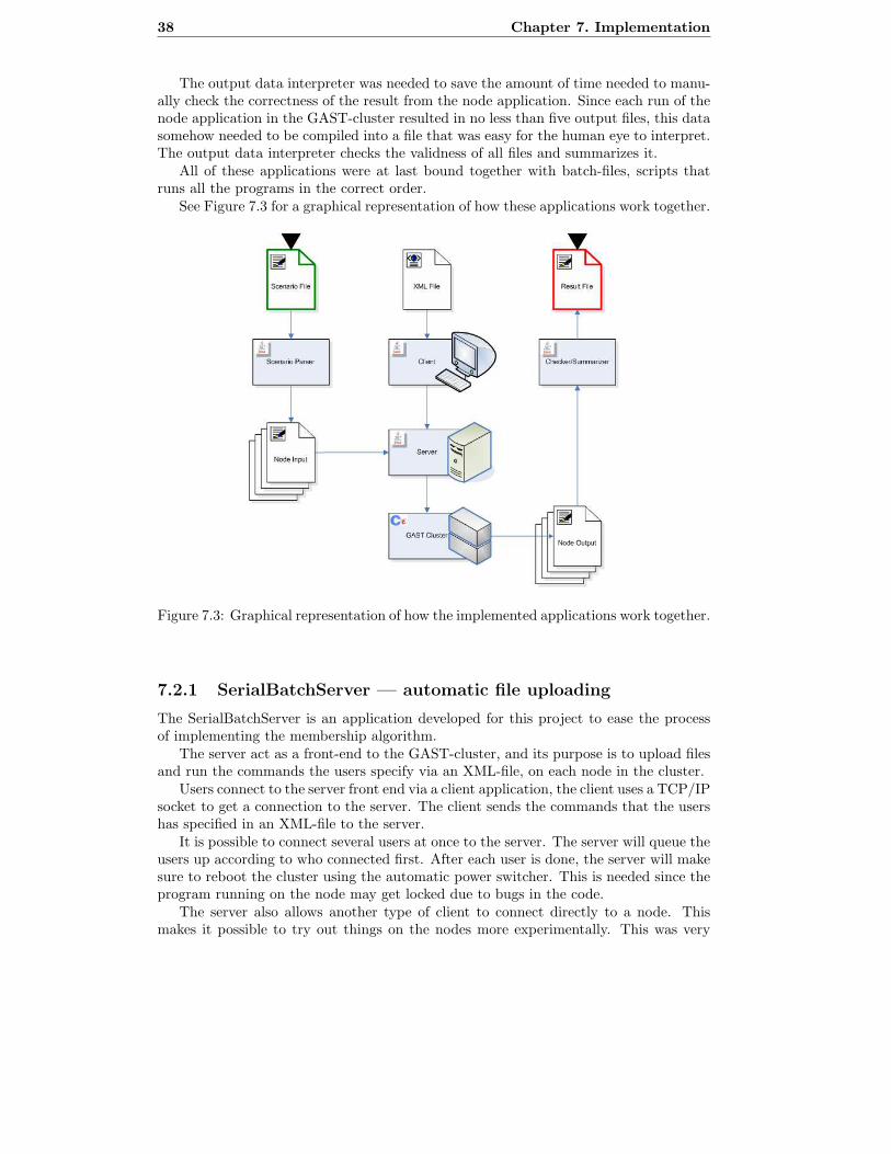
38 Chapter 7. Implementation
The output data interpreter was needed to save the amount of time needed to manu-ally check the correctness of the result from the node application. Since each run of thenode application in the GAST-cluster resulted in no less than five output files, this datasomehow needed to be compiled into a file that was easy for the human eye to interpret.The output data interpreter checks the validness of all files and summarizes it.
All of these applications were at last bound together with batch-files, scripts thatruns all the programs in the correct order.
See Figure 7.3 for a graphical representation of how these applications work together.
Figure 7.3: Graphical representation of how the implemented applications work together.
7.2.1 SerialBatchServer — automatic file uploading
The SerialBatchServer is an application developed for this project to ease the processof implementing the membership algorithm.
The server act as a front-end to the GAST-cluster, and its purpose is to upload filesand run the commands the users specify via an XML-file, on each node in the cluster.
Users connect to the server front end via a client application, the client uses a TCP/IPsocket to get a connection to the server. The client sends the commands that the usershas specified in an XML-file to the server.
It is possible to connect several users at once to the server. The server will queue theusers up according to who connected first. After each user is done, the server will makesure to reboot the cluster using the automatic power switcher. This is needed since theprogram running on the node may get locked due to bugs in the code.
The server also allows another type of client to connect directly to a node. Thismakes it possible to try out things on the nodes more experimentally. This was very

7.2. Helper software development 39
useful when running the live demonstration on the node application, where we couldpull the connection to a node and see all the other nodes correspond to that action.
For a more thorough explanation of what the server can do and how to use it, seeAppendix E.
7.2.2 ScenarioParser — simplifying scenario specification
An application named ScenarioParser was made to simplify the submitting of a scenariospecification. The ScenarioParser parses a text file and generates one unique text filefor each node in the GAST cluster. The original text file contains both information thatis the same for all nodes and also information that is specific for each node.
The choice of file format for the input data to the node application was not chosen foran arbitrary reason. Several tricky cases had already been expressed in that file formatfor a simulated version of the membership algorithm written by Bergenhem. Thesescenarios became the foundation for our testing. A few scenarios to test the simplescenarios was also written to test the core functionality of the node application.
Examples of parameters that are the same among all the nodes are the size of thecluster and the length of the test run. Parameters that are unique for each node issuch as what type of fault and when it occurs. More about these and the rest of theparameters can be read in Appendix D.
7.2.3 Checker — summarizing the test run log-files
The Node application on each node generates one-log file each. These log files containsa selectable amount of data about the test scenario that was executed. The differenttypes of data is, information about the membership vector, golden states and so on,more can be read in Appendix C.
The Checker takes the data from all of the log files from each node and puts theinteresting information together in one file. The Checker also do a comparison of themembership vector and the golden states to make a notification of that there is a differ-ence. The amount of information in the summarized file is selectable, more about thiscan be read in Appendix C.
7.2.4 TestPlatform — tying it all together
The TestPlatform is a collection of batch-scripts used to tie the developed softwaretogether. The scripts are quite simple, and allow the user to run a whole set of scenarioswith only one command. The output for all scenarios is stored in folders and the outputwill have to be reviewed manually by the user.
The scripts are make.bat, run.bat, server.bat and terminal.bat. See AppendixF for more information on these scripts.

40 Chapter 7. Implementation

Chapter 8
Results
The results from this project are gathered from a large number of test runs. The testruns ranged from longer tests to very short tests called scenarios. How the tests wereperformed and the results of the tests will be explained in this chapter.
8.1 Correctness verification
The main objective of this project was to verify that the membership algorithm workedcorrectly, implemented for a cluster consisting of GAST nodes. This was verified using aseries of tests of the implementation. The tests had to cover as much realistic events astime permitted to be able to draw any final conclusions about the membership algorithm.
It is however important to remember that no matter the amount of tests done, itis impossible to show that the membership algorithm is completely fool proof usingthis approach. This is merely a verification that the membership algorithm works as itshould for most cases on this specific piece of hardware.
8.1.1 Verification procedure
The tests, on which the results are primarily based upon, consists of a set of very shorttest scenarios. Each of those test scenarios is specified to be running for 20 FlexRaycycles, not all test scenarios facilitate all the 20 cycles though.
Even if 20 cycles does not sound much, it is more than enough to create a verybig set of tricky test scenarios which should challenge the membership algorithm. Thescenarios are specified in such a way that one or more nodes break down at a time wherethe algorithm is most likely not to be able to handle it.
The cycle frequency for the FlexRay configuration used in the implementation of themembership algorithm is 120 Hz. The test runs will therefore be completed very fast.Each cycle will be completed in 0,008 seconds, so each test run will take roughly 0,17seconds to complete. With the overhead consisting of configuration, synchronizationand data retrieving it will take a little more time to finish an execution of the algorithm,but that time is so small that it is of no value to count it.
To evaluate whether the implementation did finish correctly or not, a golden stateis specified in the scenario file. If this golden state would not match the finishing statefor the test run it is an indication that something has gone wrong during the test run.
41
42 Chapter 8. Results
The necessary test data is stored on each node in a matrix, and retrieved after thetest run is done and stored as log files. The log files are interpreted with the Checkersoftware (see Appendix C). Checker will make sure that the log file show correct data,and then write a new file with the summary of how good the test run has performed.The final step is to manually look at and verify the summary file.
8.1.2 Test scenarios
A test scenario is a test run of the node application. During that test run faults will beinjected, which faults are injected are specified in the scenario. The faults are injectedon a slot level in a FlexRay cycle, and as such it is possible to inject a fault wherever itis wanted.
The only faults possible to inject to nodes are faults on a link level, i.e. problems onthe communication bus. With only link level faults it is however possible to simulate allthe faults necessary, as a broken node can be thought of as a node with no communicationto the other nodes at all.
It is also possible to inject fault to the processes running on the nodes. To simulatea process malfunctioning it is possible to switch the process off, and then back on againwhen the process is considered to be working again.
For the node application developed in this thesis project the file format used tospecify the scenarios is a file format created by Bergenhem to initially be used for amembership simulator he created. In the scenario file there are a number of propertiesthat must be specified, such as the total number of nodes and how many processesthere are running on each node. Aside from all those properties the fault injections arespecified. Those are specified by typing which node, which cycle, which slot and finallywhat fault will be injected.
Whenever a fault should cease it is needed to write a new event, which should bespecified as OK. This event is specified in the same way as the other types of faults.
The test scenario file also contains a special type of event called gold. The gold eventis available for testing purposes, and each gold event specifies how the membership vectorshould look at a certain point in time of the test scenario.
Totally there have been around 30 test scenarios run on the node application. Themajority of the tests have contained the most tricky scenarios that could be thoughtof. But for testing the node application there have also been a few very simple testscenarios.
8.1.3 Correctness results
Using the TestPlatform all the test scenarios have been executed. The summary files ofthe test runs have afterwards been manually verified, and those results can be found inTable 8.2 and 8.3
See Table 7.1 and 7.2 for the an explanation of the available faults.Table 8.1 shows an example of a simple test scenario. Figure 8.1 illustrates how the
slots and phases corresponds to each other.There were no tests to crash processes when testing on four nodes. However on the
test results with five nodes a fault was injected on node level if the process columncontains a dash (’-’). Otherwise it was injected on the local process with the numbercorresponding to the value in that column.
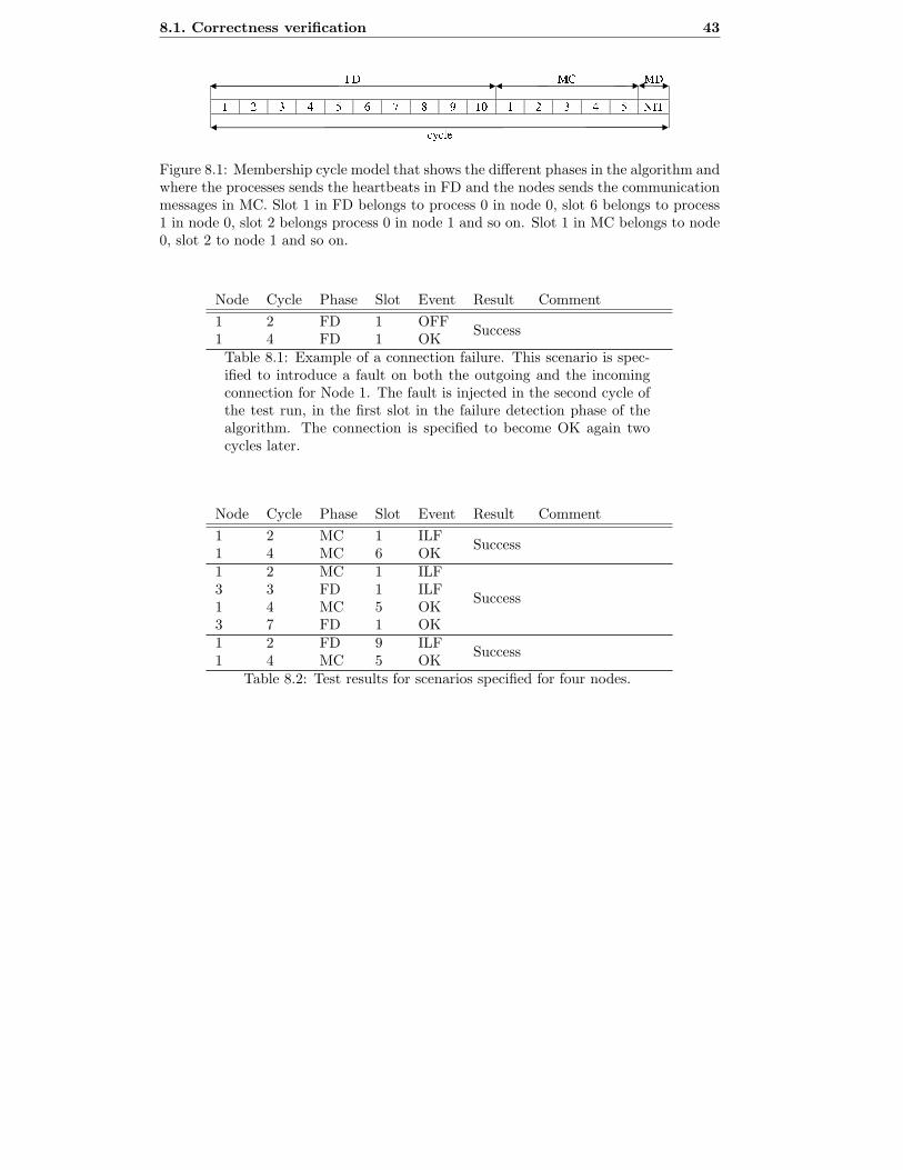
8.1. Correctness verification 43
Figure 8.1: Membership cycle model that shows the different phases in the algorithm andwhere the processes sends the heartbeats in FD and the nodes sends the communicationmessages in MC. Slot 1 in FD belongs to process 0 in node 0, slot 6 belongs to process1 in node 0, slot 2 belongs process 0 in node 1 and so on. Slot 1 in MC belongs to node0, slot 2 to node 1 and so on.
Node Cycle Phase Slot Event Result Comment
1 2 FD 1 OFFSuccess
1 4 FD 1 OKTable 8.1: Example of a connection failure. This scenario is spec-ified to introduce a fault on both the outgoing and the incomingconnection for Node 1. The fault is injected in the second cycle ofthe test run, in the first slot in the failure detection phase of thealgorithm. The connection is specified to become OK again twocycles later.
Node Cycle Phase Slot Event Result Comment
1 2 MC 1 ILFSuccess
1 4 MC 6 OK1 2 MC 1 ILF
Success3 3 FD 1 ILF1 4 MC 5 OK3 7 FD 1 OK1 2 FD 9 ILF
Success1 4 MC 5 OK
Table 8.2: Test results for scenarios specified for four nodes.
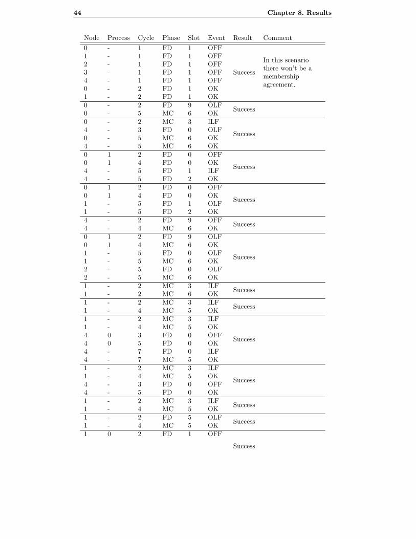
44 Chapter 8. Results
Node Process Cycle Phase Slot Event Result Comment
0 - 1 FD 1 OFF
Success
In this scenariothere won’t be amembershipagreement.
1 - 1 FD 1 OFF2 - 1 FD 1 OFF3 - 1 FD 1 OFF4 - 1 FD 1 OFF0 - 2 FD 1 OK1 - 2 FD 1 OK0 - 2 FD 9 OLF
Success0 - 5 MC 6 OK0 - 2 MC 3 ILF
Success4 - 3 FD 0 OLF0 - 5 MC 6 OK4 - 5 MC 6 OK0 1 2 FD 0 OFF
Success0 1 4 FD 0 OK4 - 5 FD 1 ILF4 - 5 FD 2 OK0 1 2 FD 0 OFF
Success0 1 4 FD 0 OK1 - 5 FD 1 OLF1 - 5 FD 2 OK4 - 2 FD 9 OFF
Success4 - 4 MC 6 OK0 1 2 FD 9 OLF
Success
0 1 4 MC 6 OK1 - 5 FD 0 OLF1 - 5 MC 6 OK2 - 5 FD 0 OLF2 - 5 MC 6 OK1 - 2 MC 3 ILF
Success1 - 2 MC 6 OK1 - 2 MC 3 ILF
Success1 - 4 MC 5 OK1 - 2 MC 3 ILF
Success
1 - 4 MC 5 OK4 0 3 FD 0 OFF4 0 5 FD 0 OK4 - 7 FD 0 ILF4 - 7 MC 5 OK1 - 2 MC 3 ILF
Success1 - 4 MC 5 OK4 - 3 FD 0 OFF4 - 5 FD 0 OK1 - 2 MC 3 ILF
Success1 - 4 MC 5 OK1 - 2 FD 5 OLF
Success1 - 4 MC 5 OK1 0 2 FD 1 OFF
Success
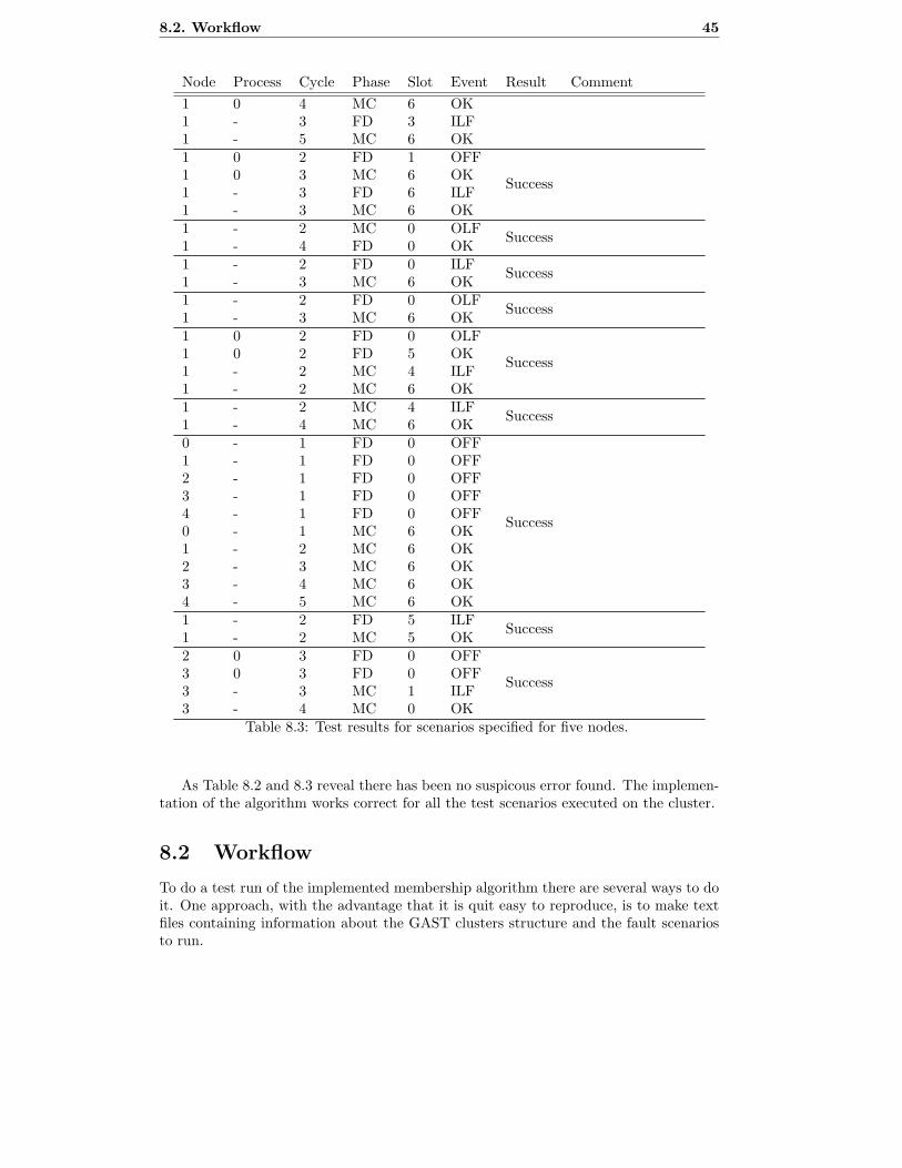
8.2. Workflow 45
Node Process Cycle Phase Slot Event Result Comment
1 0 4 MC 6 OK1 - 3 FD 3 ILF1 - 5 MC 6 OK1 0 2 FD 1 OFF
Success1 0 3 MC 6 OK1 - 3 FD 6 ILF1 - 3 MC 6 OK1 - 2 MC 0 OLF
Success1 - 4 FD 0 OK1 - 2 FD 0 ILF
Success1 - 3 MC 6 OK1 - 2 FD 0 OLF
Success1 - 3 MC 6 OK1 0 2 FD 0 OLF
Success1 0 2 FD 5 OK1 - 2 MC 4 ILF1 - 2 MC 6 OK1 - 2 MC 4 ILF
Success1 - 4 MC 6 OK0 - 1 FD 0 OFF
Success
1 - 1 FD 0 OFF2 - 1 FD 0 OFF3 - 1 FD 0 OFF4 - 1 FD 0 OFF0 - 1 MC 6 OK1 - 2 MC 6 OK2 - 3 MC 6 OK3 - 4 MC 6 OK4 - 5 MC 6 OK1 - 2 FD 5 ILF
Success1 - 2 MC 5 OK2 0 3 FD 0 OFF
Success3 0 3 FD 0 OFF3 - 3 MC 1 ILF3 - 4 MC 0 OK
Table 8.3: Test results for scenarios specified for five nodes.
As Table 8.2 and 8.3 reveal there has been no suspicous error found. The implemen-tation of the algorithm works correct for all the test scenarios executed on the cluster.
8.2 Workflow
To do a test run of the implemented membership algorithm there are several ways to doit. One approach, with the advantage that it is quit easy to reproduce, is to make textfiles containing information about the GAST clusters structure and the fault scenariosto run.

46 Chapter 8. Results
To specify the fault scenario it is of course also possible to do it manually with theinterface implemented on the GAST cluster with the connected PC or over TCP/IP viathe connected PC.
The text file with information about the GAST cluster and the fault scenarios areparsed with a application written in java to generate a unique scenario file, one for eachnode. To use the text file together with the cluster, an XML file is required to handlethe file system and the communication with the cluster.
When the test is performed the GAST cluster generates a output file from each nodein the cluster. The output file contains the node’s view at each cycle during the testrun. Since all of this information is a little difficult to overview there is an applicationto merge the information from the different output files.
8.3 Performance
To measure the performance of the implemented membership algorithm one need toconsider both the use of the CPU on the G2 board and bandwidth used for communi-cation between the FlexRay boards. A third thing to consider is that the performanceis dependent on the amount of fault occurring. If there are no faults at all, there is noneed to do a voting among the processes. This saves both CPU usage and bandwidth. Ifthere is a fault in a node the performance in this node may differ from the performancein other nodes.
For example if node 1 has an OLF (see Table 7.1), node 1 will try to reintegrateevery cycle if the back-off-time is sat to zero cycles, this will increase the amount ofCPU usage. Since no other node in the cluster will receive the join request they will notneed to do the voting and therefore have the same low amount of CPU and bandwidthusage until node 1 does not have an OLF anymore.
In case of an ILF in node 1 and back-off-time set to zero cycles, there will be a votingperformed every cycle that votes against that node 1 should reintegrate.
8.3.1 Theoretical
To calculate the bandwidth used from one node in a cluster that is configured for ourimplementation there are several parameters needed to take into consideration. Thefirst most obvious parameter is of course the FlexRay cycle frequence (FF). A secondparameter is how much data in one cycle is dedicated to one node, this is depending onhow many processes (N PROC) are on the actual node. The rest of the parameters arehow many bits used for overhead (OH), number of bytes (NBs for static and NBp fordynamic), size of a byte (BS).
These parameters inserted in the following formula will give how much data can betransfered during a second from one node when a certain per cent faults (fault%) occur,faults that leads to that a voting is necessary.
(NBs ∗ BS − OH) ∗ N PROC + 100−fault%100
(NBd ∗ BS)
BS∗ FF = n(byte/s)
An example with a fault rate of 10% and the actual values from the implementednode application gives the following parameters:NBs = 24 bytes
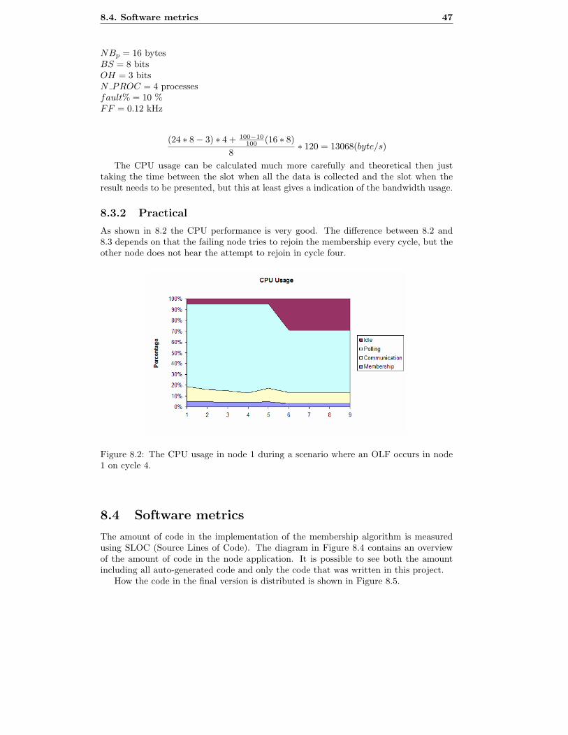
8.4. Software metrics 47
NBp = 16 bytesBS = 8 bitsOH = 3 bitsN PROC = 4 processesfault% = 10 %FF = 0.12 kHz
(24 ∗ 8 − 3) ∗ 4 + 100−10
100(16 ∗ 8)
8∗ 120 = 13068(byte/s)
The CPU usage can be calculated much more carefully and theoretical then justtaking the time between the slot when all the data is collected and the slot when theresult needs to be presented, but this at least gives a indication of the bandwidth usage.
8.3.2 Practical
As shown in 8.2 the CPU performance is very good. The difference between 8.2 and8.3 depends on that the failing node tries to rejoin the membership every cycle, but theother node does not hear the attempt to rejoin in cycle four.
Figure 8.2: The CPU usage in node 1 during a scenario where an OLF occurs in node1 on cycle 4.
8.4 Software metrics
The amount of code in the implementation of the membership algorithm is measuredusing SLOC (Source Lines of Code). The diagram in Figure 8.4 contains an overviewof the amount of code in the node application. It is possible to see both the amountincluding all auto-generated code and only the code that was written in this project.
How the code in the final version is distributed is shown in Figure 8.5.

48 Chapter 8. Results
Figure 8.3: The CPU usage in node 3 during a scenario where an OLF occurs in node1 on cycle 4.
Figure 8.4: Amount of code in the node application. The first version is the basicversion with reintegration, the second version is the basic version with reintegration anddynamic operation and the third version is the final version.
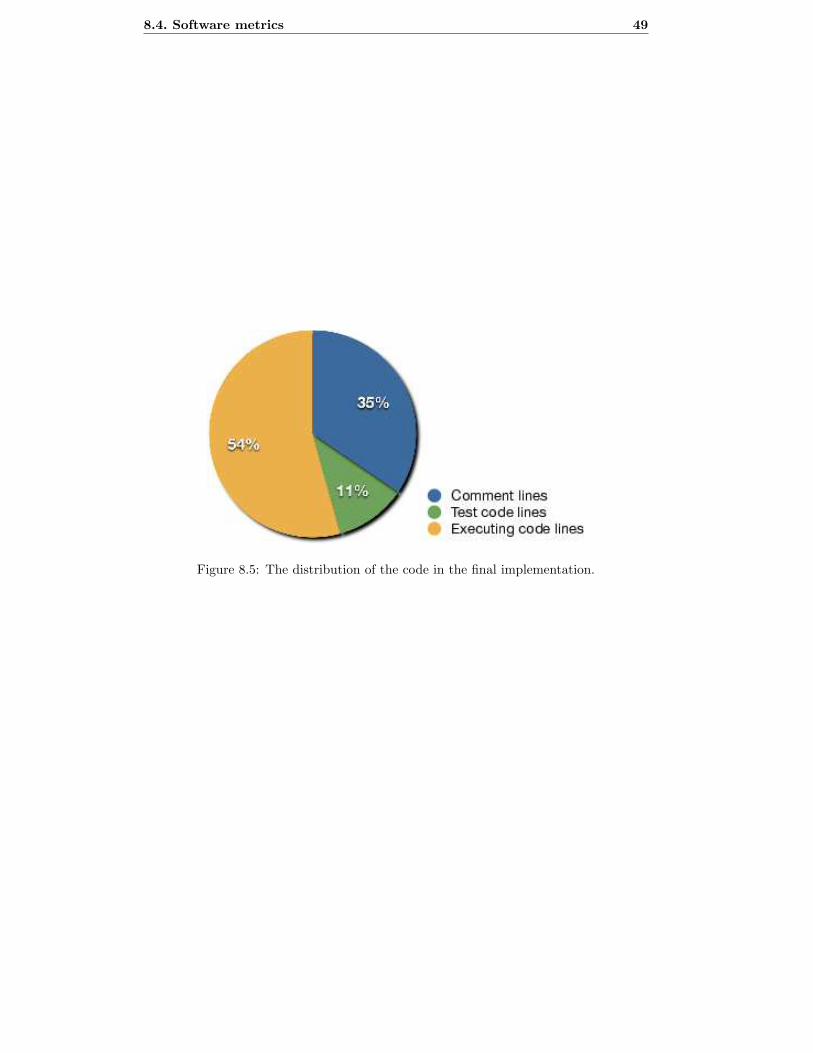
8.4. Software metrics 49
Figure 8.5: The distribution of the code in the final implementation.

50 Chapter 8. Results

Chapter 9
Conclusions
This chapter contains our final conclusions drawn from the implementation of the pro-tocol and from the results of the test runs on the implementation.
9.1 Conclusions from implementing the protocol
After doing this implementation a few things that one may need to consider has beendiscovered.
The first thing that comes to mind is that the FlexRay controller got some restric-tions. Since it need the data available more than one slot before it is actually sent itis not possible to use the algorithm exactly as it is described. The algorithm suggeststhat if a node detects a fault in a slot, where the node is about to send a message, itshould report this by setting the membership request flag in the message. Since this isnot possible it has to be solved by either not setting that flag or by not allowing themembership group to have processes that sends their static message next to each otherin the FlexRay configuration.
It was also discovered how important it is that a node shuts itself down if it crashes.Not doing so can indeed lead to strange results.
Storing the membership view in a set data type limits the expandability of theprogram. It is difficult to set additional parameters for each process in the set. If anew implementation was to be done we would recommend that it natively could handleparameters such as number of send attempts, what type of fault an excluded processsuffered from etc.
One need to be careful with using the back-off-time. If the back-off-time has aninappropriate value the system may enter a deadlock where it never starts up. Thismay happen if for example a system with four nodes has a back-off-time set to two. Ifunlucky the first cycle there are two nodes trying to join (and start up) the membership.This will not be majority and they will not be able to. The next cycle the other twonodes will try to join with the same result. So it will continue, and the membership willnever start up. Ideas to solve this could be to have a random back-off-time each joinattempt. It could also be to set the back-off-time to a unique prime number for eachnode.
51
52 Chapter 9. Conclusions
9.2 Conclusions from the results
The result data has showed that the membership protocol worked very well.Performance measures reveals that the CPU-usage of the algorithm is kept low.
The bandwidth available when using the protocol is however very low compared to themaximum possible in the FlexRay protocol. Reasons for this include low performancedrivers. It took quite long to send and receive messages for a node. The biggest limit forthe bandwidth is however the FlexRay configuration used. The FlexRay configurationis designed to maximize the available CPU-time, and does this by maximizing the voidbetween each slot. This is in turn a side effect from not having a proper operatingsystem available.
9.3 Limitations
One hardware restriction is about how far ahead the data has to be committed andthe actual buffer unlocked before transmitting data. To transmit data in the static orthe dynamic segment at slot n, the buffer must first be locked, the data must then becommitted and the buffer unlocked not later than four micro-ticks before the beginningof slot n-1 [16]. The existing drivers locks the buffers by repeatedly trying to lock ituntil it works. This is obviously consumes much CPU time, and a new set of driverswhich solves this issue would be needed to use this CPU time for something productive.
The implementation of the node application adds another limitation to the algorithmthat is that the number of processes in a membership may not be larger than 32. This isdue to that a set is stored as a bit combination in the PowerPC in this implementation.
9.4 Future work
The future work needed to be done is to implement a more advanced real-time operatingsystem so that our implementation of the membership algorithm can be used togetherwith a more advanced application. As of today, the test platform consisting of a coupleof nodes with a G2 board and a FlexRay board does not allow interrupt handling thatwell, which forces us to poll for events.
A good improvement for the future would be to extend the protocol so that it supportseveral membership groups in the same system.
As Bergenhem is working on a new version of this protocol which is more faulttolerant it may be of interest to update this application to reflect that protocol.

Chapter 10
Acknowledgements
The most important person for the realization of this master’s thesis is Carl Bergenhem,who has supplied us with a lot of articles and has helped us in many ways. So we wish tosend many thanks to Carl for suggesting and assisting us with this interesting project.
We also would like to thank Mattias Bergstrom and Johan Hogberg for their workon their thesis project which gave us much inspiration and has provided us with a goodcode base to base our work upon.
Many thanks to Rickard Svenningsson and Mansoor Chaudhry for their great intro-duction of how to work with the GAST boards, and how to use to ODEEP FlexRayConfigurator.
Finally we would like to thank Mikael Rannar for being our assistant at the Depart-ment of Computing Science at Umea Universitet.
53

54 Chapter 10. Acknowledgements

References
[1] Eclipse an open development platform. http://www.eclipse.org/.
[2] M. Ayoubi, T. Demmeler, H. Leffler, and P. Kohn. X-by-wire functionality, per-formance and infrastructure. Presented at the Convergence Conf. 2004, Detroit,MI.
[3] C. Bergenhem and J. Karlsson. A configurable membership service for active safetytechnical report. -, 2007.
[4] M. Bergstrom and J. Hogberg. Implementation of membership algoritms in gast-cluster with flexray. Technical report, Chalmers University of Technology, 2007.
[5] Cygwin. http://www.cygwin.com/.
[6] G. Grunsteidl. Dezentrales redundanzmanagement in vertilten echtzeitsystemen.Technical report, Technical University of Vienna, 1993.
[7] R. Johansson and L.-A. Johansson. G2 board, manual. Technical report, QRtechAB, 2007.
[8] R. Johansson, D. Lundgren, and S. Andersson. Rtcom boards, user manual. Tech-nical report, QRtech AB, 2006.
[9] Nicolas Navet, Yeqiong Song, FranCoise Simonot-Lion, and Cedric Wilwert. Trendsin automotive communication systems. Technical report, Loria Laboratory, France,2005.
[10] Ralf Schlatterbeck. Membership service: What it is and why you need one for asafety critical system. Technical report, TTTech Computer technik AG, 2002.
[11] Subclipse. http://subclipse.tigris.org/.
[12] Subversion. http://subversion.tigris.org/.
[13] R. Svenningsson and M. Chaudry. Flexray-based communication of diagnostic infor-mation in gast-environment. Technical report, Chalmers University of Technology,2007.
[14] GCC the Gnu Compiler Collection. http://gcc.gnu.org/.
[15] Unknown. Flexray - the communication system for advanced automotive controlapplications. http://www.flexray.com/ (visited 2007-06-29).
55

56 REFERENCES
[16] Unknown. Mfr4200 data sheet. Technical report, Freescale, P.O. Box 5405, Denver,Colorado 80217, 2006.
[17] P. Souto V. Rosset and F. Vasques. A group membership protocol for communica-tion systems with both static and dynamic scheduling. -, 2007.
[18] N. Vorkapic and J. Myhrman. Development of and open dependable electrical andelectronics platform. Technical report, Chalmers University of Technology, 2006.
Appendix A
Glossary
ABS Anti-lock Braking system.BDM Device used to update the software for the HCS12 controller.CAN Controller Area Network.CEDES Cost Efficient Dependable Electronic Systems.Checker Software to simplify the checking of data.Consensus To reach the same decition.CVS Concurrent Versions System.Cygwin A Linux like environment for Windows.DEAD Status of a node that does not work properly.Eclipse A IDE written in java.ECU Electronic Control Unit.ELp Electronics and Software.ESP Electronic Stability Program.FD Failure Detection Phase, first phase in the membership algo-
rithm.FlexRay Time-triggered, with support for event-triggered, communica-
tion system for use in vehicles.G1 and G2 Two ECU boards in the GAST project.G2DBG The debugger on the G2 board.GAST General Application Development Boards for Safety Critical
Time-Triggered Systems.GCC GNU Compiler Collection.GEE GAST Eclipse Environment.HCS12 Freescale microcontroller.Hearbeat A membership flag.IDE Integrated Development Environment.ILF Incomming Link Failure.MC Membership Communication Phase, second phase in the mem-
bership algorithm.MD Membership Detection Phase, third and last phase in the mem-
bership algorithm.Membership al-gorithm
The algorithm that gives a correct view of the working nodes.
57

58 Chapter A. Glossary
MFR4200 The FlexRay controller chip mounted on the RTComm fromGAST.
MPC565 a CPU on the G2 board.mT och µT Macrotick and microtick.NIT Network Idle Time.ODEEP FlexRayConfigurator
A application to generate C-code to operate the FlexRaydrivers.
OLF Outgoing Link failure.Opinion A parameter in the membership algorithm that stores the cur-
rent nodes opinion.RTComm Real Time Communication board for GAST.RTOS Real Time Operatin System.S19 The file format that can be read of a CPU on a G2 board.ScenarioParser A application that translates the scenarios.SerialBatchServer A application that handles the connections to a GAST-cluster.SLOC Source Lines Of Code.SP SP Technical Research Institute of Sweden.Subclipse A Subversion plugin for Eclipse.SVN Subversion.TDMA Time Division Multiple Access.TTCAN A version of CAN that is time-triggered.TTP/C Time-Triggered Protocol class C.X-by-wire Electronic control of something mechanical, e.g. brakes, steer-
ing.Xml Extensible Markup Language.
Table A.1: Glossary.

Appendix B
Membership Node Applicationuser’s guide
This is a node application that has been developed for a master’s thesis project. Thegoal of the application has been to test how a membership algorithm works in a realenvironment consisting of a GAST cluster with several G2 cards coupled together withFlexRay cards as communication controller.
The algorithm which has been implemented has been developed by Carl Bergenhem,and is the third iteration of the algorithm. See the features list later for what thisalgorithm can handle.
This implementation is not intended to be used as a final product. Several limitationsmakes this unsuitable for real use. These limitations will be listed later.
B.1 Features
– Membership.
• Dynamic reintegration.
• Multiple processes per node.
• Performs the membership communication/decision phase only when a changehas been detected.
– Fault-injection down to a slot level.
– Non-blocking I/O.
– Can run both short scenarios and long real-time tests.
– Support for dual channel usage.
– Output available for both performance tests and correctness tests.
– Synchronization on the startup for all nodes.
– Several user programs for demo purpose.
– Nodes can handle loss of physical connection to the rest of the cluster.
59
60 Chapter B. Membership Node Application user’s guide
B.2 Requirements
– GAST cluster consisting of G2 and FlexRay cards.
– The G2-DebuggerPPC-BETA software installed on the G2 card.
– Windows HyperTerminal or the SerialBatchServer software.
– All G2 cards in the GAST cluster connected to a PC.
– The GEE environment installed.
– The ODEEP FlexRay Configurator if any change to the FlexRay configuration isneeded.
B.3 User manual
First the node needs to be compiled. In a terminal, use the command ’make’ whilestanding in the project root to compile the program. This will generate a number of*.s19 files in the debug folder.
Then the *.s19 files needs to be uploaded to the node. If it isn’t already uploaded,this is how you do:
Type ’ferase’ in the debugger followed by ’q’. The memory where the program will beuploaded should now be erased. Type ’fload’, the debugger will await the program. Nowyou should use the internal file sending command in the console you use to communicatewith the G2 card. In HyperTerminal you use the command ’Send Text File...’ and pickthe *.s19 file to upload. Wait for it to finish. Then start the application by typing ’go10000’.
The applications will need a number of parameters to start up. It is however possibleto use the default values by just pressing enter on all the input fields to get a quick start.
Parameters v1.2 explained:
stop cycle How many cycles that will pass before the application quits.
number of nodes The number of nodes that will be connected to the cluster, a max-imum of five.
active nodes at startup Takes a node set with all the nodes that will be synchronized.
number of processes Number of processes that will run on this node, a maximum offour.
process XX user program Select which user program will be run as process XX.
B.4 Fault-injection v1.0 explained
We suggest that you use the ScenarioParser application to create fault injection sce-narios. The method used here is a bit tricky and requires the user to pay quite a lotof attention. However, here is how to use the fault injection on the node applicationmanually.
When a fault is injected it is injected in a certain phase. For example, if a fault isinjected in the failure detection phase in cycle 3, all the cycles after 3 that fault will
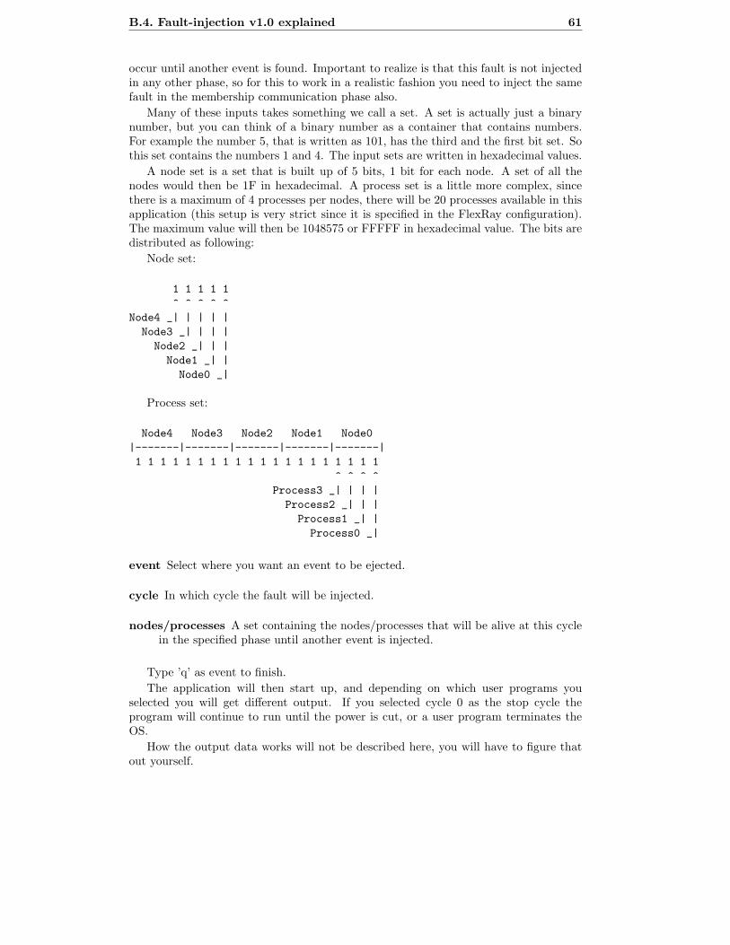
B.4. Fault-injection v1.0 explained 61
occur until another event is found. Important to realize is that this fault is not injectedin any other phase, so for this to work in a realistic fashion you need to inject the samefault in the membership communication phase also.
Many of these inputs takes something we call a set. A set is actually just a binarynumber, but you can think of a binary number as a container that contains numbers.For example the number 5, that is written as 101, has the third and the first bit set. Sothis set contains the numbers 1 and 4. The input sets are written in hexadecimal values.
A node set is a set that is built up of 5 bits, 1 bit for each node. A set of all thenodes would then be 1F in hexadecimal. A process set is a little more complex, sincethere is a maximum of 4 processes per nodes, there will be 20 processes available in thisapplication (this setup is very strict since it is specified in the FlexRay configuration).The maximum value will then be 1048575 or FFFFF in hexadecimal value. The bits aredistributed as following:
Node set:
1 1 1 1 1
^ ^ ^ ^ ^
Node4 _| | | | |
Node3 _| | | |
Node2 _| | |
Node1 _| |
Node0 _|
Process set:
Node4 Node3 Node2 Node1 Node0
|-------|-------|-------|-------|-------|
1 1 1 1 1 1 1 1 1 1 1 1 1 1 1 1 1 1 1 1
^ ^ ^ ^
Process3 _| | | |
Process2 _| | |
Process1 _| |
Process0 _|
event Select where you want an event to be ejected.
cycle In which cycle the fault will be injected.
nodes/processes A set containing the nodes/processes that will be alive at this cyclein the specified phase until another event is injected.
Type ’q’ as event to finish.
The application will then start up, and depending on which user programs youselected you will get different output. If you selected cycle 0 as the stop cycle theprogram will continue to run until the power is cut, or a user program terminates theOS.
How the output data works will not be described here, you will have to figure thatout yourself.

62 Chapter B. Membership Node Application user’s guide
B.5 User programs
Sample prog Simple program that prints the alphabet one character at a time, everysecond. For monitoring purpose the current membership opinion is also printedout each second. A node that gets an error for some reason and gets OK againwill integrate with the other nodes and print the alphabet at the same point as allthe other processes in the membership.
Monitor prog This is a utility user program that can be handy to use while doing along test run. This program will print the membership on any change. It alsoprovides the functionality to quit the node application by typing ’q’.
Jage prog Jage is a kids game where one kid hunt the other kids. If the hunter catchesanother kid, that kid will be the new hunter. This program is an example of a littlemore advanced program you can create using membership. All processes runningthis program and is part of the membership in the cluster corresponds to a playerin the Jage game.
Only sample prog and Jage prog sends a heartbeat every cycle, so it is recommendedto only run monitor prog as secondary a node process.
B.6 FlexRay setup files
The FlexRay setup files are saved in XML format and is the format supported by theODEEP FlexRay Configurator. ’cluster version4.XML’ is the final setup which is usedin this implementation.
B.7 Limitations
– The code right now supports up to 5 nodes with 4 processes on each node. Thisis quite easily updated by changing the FlexRay configuration and the clusterinitialization process.
– Due to how the set work it is not possible to have more than 32 processes includedin the membership.
– The RTOS can not control the user programs. If any user program takes too longto execute the node will be excluded from the membership.

Appendix C
Checker user’s guide
The checker is a small program which put together the result from several output filesfrom a test run to a file which is easier to interpret. The checker has different levels ofhow much output it gives to the summary file.
C.1 Requirements
Java 1.6.
C.2 User manual
The programs is located in the jar files under the dist folder.To run the program use the command ’java -jar dist/checker.jar’. The first parameter
is obligatory, it is what level of output wanted in the summary file. 0 = as little outputas possible, only writes out if there are any errors or if gold differs. 1 = all as in 0and also a summary of all nodes membership vector every cycle the test ran. 2 = allas in 1 and also writes the gold even if it doesn’t differs. The second parameter is alsoobligatory, it is the name of the file where the summary shall be written down. Thefollowing parameters are the names of the files that came from the test run. For everyname the program tries to find an scenario file that ends with ’.input’ instead of ’.txt’.This is just used if they exist and prints the scenario in the summary to make it easierto know what was run.
Example: java -jar dist/checker.jar 2 summary.txt Node0.txt Node1.txt
Node2.txt Node3.txt Node4.txt
63

64 Chapter C. Checker user’s guide
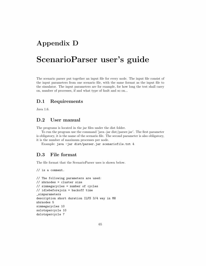
Appendix D
ScenarioParser user’s guide
The scenario parser put together an input file for every node. The input file consist ofthe input parameters from one scenario file, with the same format as the input file tothe simulator. The input parameters are for example, for how long the test shall carryon, number of processes, if and what type of fault and so on...
D.1 Requirements
Java 1.6.
D.2 User manual
The programs is located in the jar files under the dist folder.To run the program use the command ’java -jar dist/parser.jar’. The first parameter
is obligatory, it is the name of the scenario file. The second parameter is also obligatory,it is the number of maximum processes per node.
Example: java -jar dist/parser.jar scenariofile.txt 4
D.3 File format
The file format that the ScenarioParser uses is shown below.
// is a comment.
// The following parameters are used:
// nbrnodes = cluster size
// simmegacycles = number of cycles
// idlebeforejoin = backoff time
_simparameters
description short duration ILFS 3/4 way in MH
nbrnodes 5
simmegacycles 10
sslotspercycle 10
dslotspercycle 7
65
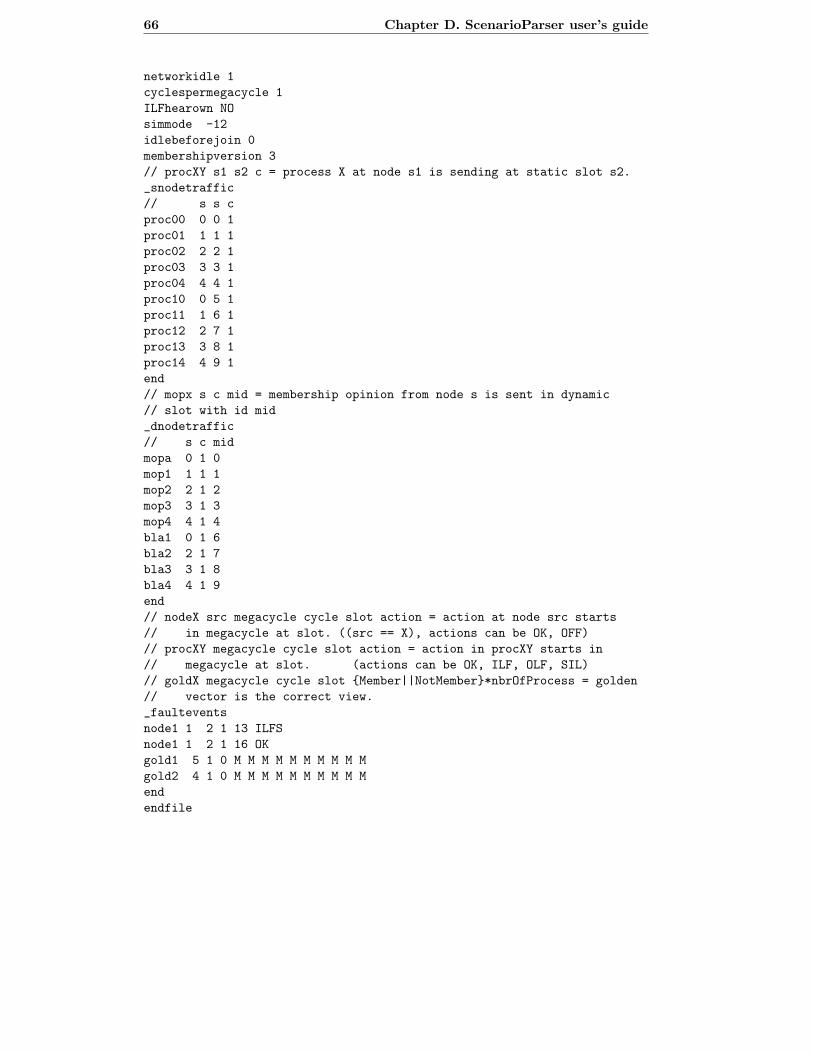
66 Chapter D. ScenarioParser user’s guide
networkidle 1
cyclespermegacycle 1
ILFhearown NO
simmode -12
idlebeforejoin 0
membershipversion 3
// procXY s1 s2 c = process X at node s1 is sending at static slot s2.
_snodetraffic
// s s c
proc00 0 0 1
proc01 1 1 1
proc02 2 2 1
proc03 3 3 1
proc04 4 4 1
proc10 0 5 1
proc11 1 6 1
proc12 2 7 1
proc13 3 8 1
proc14 4 9 1
end
// mopx s c mid = membership opinion from node s is sent in dynamic
// slot with id mid
_dnodetraffic
// s c mid
mopa 0 1 0
mop1 1 1 1
mop2 2 1 2
mop3 3 1 3
mop4 4 1 4
bla1 0 1 6
bla2 2 1 7
bla3 3 1 8
bla4 4 1 9
end
// nodeX src megacycle cycle slot action = action at node src starts
// in megacycle at slot. ((src == X), actions can be OK, OFF)
// procXY megacycle cycle slot action = action in procXY starts in
// megacycle at slot. (actions can be OK, ILF, OLF, SIL)
// goldX megacycle cycle slot {Member||NotMember}*nbrOfProcess = golden
// vector is the correct view.
_faultevents
node1 1 2 1 13 ILFS
node1 1 2 1 16 OK
gold1 5 1 0 M M M M M M M M M M
gold2 4 1 0 M M M M M M M M M M
end
endfile

Appendix E
SerialBatchServer user’s guide
For the master’s thesis project there was a need for an application to upload user pro-grams to the node cluster in a convenient and fast way. The manual way of doing it viathe windows application HyperTerminal took too long and was very awkward.
This application started out as a very simple program for uploading files to multipleserial connection. But the application evolved and eventually became a very convenientprogram for communicating and working with the GAST G2 card. Although this ap-plication is developed with the GAST G2 card in mind, this application is very generaland should work with any device connected to the serial port.
The application works in a server-client philosophy. This allows also other computersto work with the cluster even though they are not physically connected to the cluster.
Figure E.1: Diagram showing how the node cluster is connected to a PC via a server.
E.1 Features
– Direct communication with the cluster via remote terminals.
– It is possible to connect several remote terminals to every node.
– Node settings are specified with the XML-file format specified later.
– In the node settings file it is possible write a macro to the node.
– Progress bar when uploading files.
67
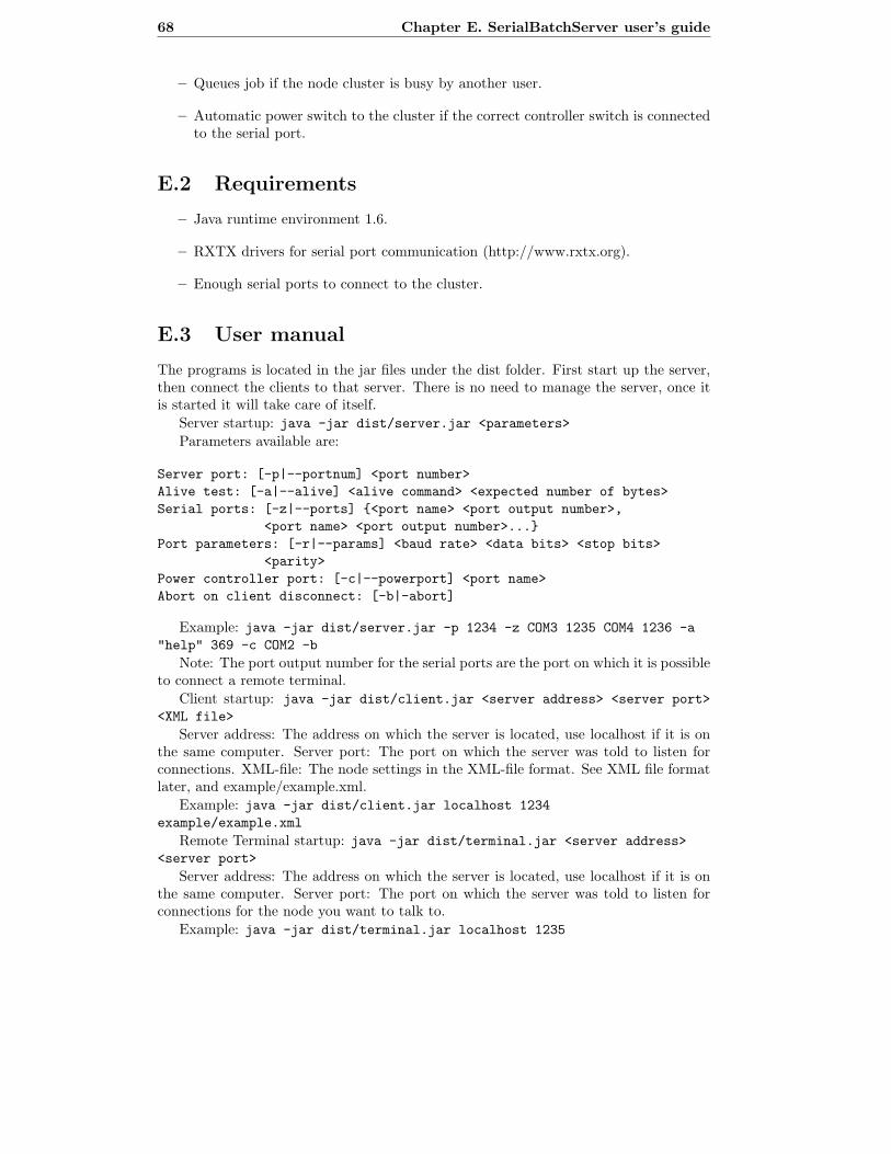
68 Chapter E. SerialBatchServer user’s guide
– Queues job if the node cluster is busy by another user.
– Automatic power switch to the cluster if the correct controller switch is connectedto the serial port.
E.2 Requirements
– Java runtime environment 1.6.
– RXTX drivers for serial port communication (http://www.rxtx.org).
– Enough serial ports to connect to the cluster.
E.3 User manual
The programs is located in the jar files under the dist folder. First start up the server,then connect the clients to that server. There is no need to manage the server, once itis started it will take care of itself.
Server startup: java -jar dist/server.jar <parameters>
Parameters available are:
Server port: [-p|--portnum] <port number>
Alive test: [-a|--alive] <alive command> <expected number of bytes>
Serial ports: [-z|--ports] {<port name> <port output number>,
<port name> <port output number>...}
Port parameters: [-r|--params] <baud rate> <data bits> <stop bits>
<parity>
Power controller port: [-c|--powerport] <port name>
Abort on client disconnect: [-b|-abort]
Example: java -jar dist/server.jar -p 1234 -z COM3 1235 COM4 1236 -a
"help" 369 -c COM2 -b
Note: The port output number for the serial ports are the port on which it is possibleto connect a remote terminal.
Client startup: java -jar dist/client.jar <server address> <server port>
<XML file>
Server address: The address on which the server is located, use localhost if it is onthe same computer. Server port: The port on which the server was told to listen forconnections. XML-file: The node settings in the XML-file format. See XML file formatlater, and example/example.xml.
Example: java -jar dist/client.jar localhost 1234
example/example.xml
Remote Terminal startup: java -jar dist/terminal.jar <server address>
<server port>
Server address: The address on which the server is located, use localhost if it is onthe same computer. Server port: The port on which the server was told to listen forconnections for the node you want to talk to.
Example: java -jar dist/terminal.jar localhost 1235
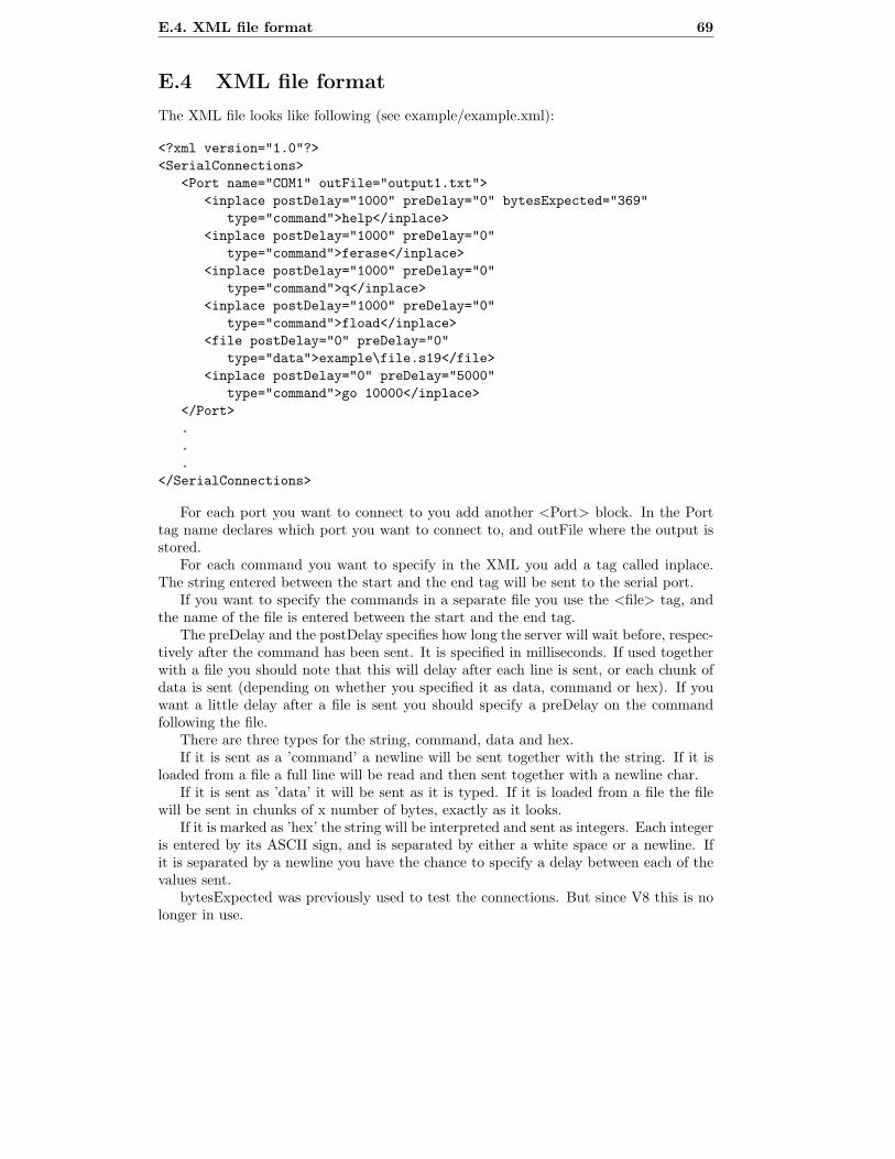
E.4. XML file format 69
E.4 XML file format
The XML file looks like following (see example/example.xml):
<?xml version="1.0"?>
<SerialConnections>
<Port name="COM1" outFile="output1.txt">
<inplace postDelay="1000" preDelay="0" bytesExpected="369"
type="command">help</inplace>
<inplace postDelay="1000" preDelay="0"
type="command">ferase</inplace>
<inplace postDelay="1000" preDelay="0"
type="command">q</inplace>
<inplace postDelay="1000" preDelay="0"
type="command">fload</inplace>
<file postDelay="0" preDelay="0"
type="data">example\file.s19</file>
<inplace postDelay="0" preDelay="5000"
type="command">go 10000</inplace>
</Port>
.
.
.
</SerialConnections>
For each port you want to connect to you add another <Port> block. In the Porttag name declares which port you want to connect to, and outFile where the output isstored.
For each command you want to specify in the XML you add a tag called inplace.The string entered between the start and the end tag will be sent to the serial port.
If you want to specify the commands in a separate file you use the <file> tag, andthe name of the file is entered between the start and the end tag.
The preDelay and the postDelay specifies how long the server will wait before, respec-tively after the command has been sent. It is specified in milliseconds. If used togetherwith a file you should note that this will delay after each line is sent, or each chunk ofdata is sent (depending on whether you specified it as data, command or hex). If youwant a little delay after a file is sent you should specify a preDelay on the commandfollowing the file.
There are three types for the string, command, data and hex.If it is sent as a ’command’ a newline will be sent together with the string. If it is
loaded from a file a full line will be read and then sent together with a newline char.If it is sent as ’data’ it will be sent as it is typed. If it is loaded from a file the file
will be sent in chunks of x number of bytes, exactly as it looks.If it is marked as ’hex’ the string will be interpreted and sent as integers. Each integer
is entered by its ASCII sign, and is separated by either a white space or a newline. Ifit is separated by a newline you have the chance to specify a delay between each of thevalues sent.
bytesExpected was previously used to test the connections. But since V8 this is nolonger in use.

70 Chapter E. SerialBatchServer user’s guide
Appendix F
TestPlatform user’s guide
Contains a number of batch scripts that tie all the applications (used for testing themembership node application) together.
Using these scripts makes testing scenario files much more efficient than using theapplication on their own.
F.1 Features
– Possible to compile, upload and test with only one command line.
– Can test single files, and also whole folders with scenario files.
F.2 Requirements
– The SerialBatchServer package available.
– The Checker application available.
– The ScenarioParser application available.
– The GEE environment installed.
F.3 Installation
1. The file path of the environment should be ’C:\MembershipData’. If it is inanother file path the XML files need to be updated to reflect that.
2. Modify the header of ’make.bat’ so that it points to the correct file paths.
3. Modify the header of ’run.bat’ so that it points to the correct file paths.
4. Modify the header of ’server.bat’ so that it points to the correct file paths, this filealso needs to be updated so the correct serial ports are loaded at server startup.
5. Modify the header of ’terminal.bat’ so that it points to the correct file paths, thisneeds to be changed so that it connects to the ports that was specified in the’server.bat’ script.
71

72 Chapter F. TestPlatform user’s guide
F.4 Scripts
None of the scripts is really needed, they are all available to simplify the work process.make.bat: Compiles the program referred to in the file, and copies the binaries
created to the ’input’ folder.run.bat: Run a scenario file on the cluster, a server needs to be up and running for
this to work.server.bat: Starts a server with the default parameters.terminal.bat: If the server is started with the default parameters you can connect to
a node with this program.
F.5 User manual
All commands are typed in the command prompt, start the command prompt by pressingRun in the Start menu, and typing cmd in the run window.
Start up a server:
1. Open a new command prompt.
2. Type ’cd /D C:\MembershipData’.
3. Start the server by typing ’server.bat’.
Run a scenario:
1. Open a new command prompt.
2. Type ’cd /D C:\MembershipData’.
3. Type ’make.bat’ to compile the membership node application.
4. To run a single scenario file, in the command prompt in C:\MembershipData\type: ’run file <scenariofile> <XML file>’
5. To run a whole scenario dir, in the command prompt in C:\MembershipData\type: ’run dir <scenariodir> <XML file>’
6. It is possible to repeat the last run scenario by typing: ’run run <XML file>’
7. All output data will be placed in ’C:\MembershipData\output\ <scenario dir|file>’.
There are two XML files available as default in this package.
– ’go.xml’ is used to just run the node application.
– ’upload and run.xml’ is used to first upload the node application and then run it.
Connect to a node via the server:
1. Open a new command prompt.
2. Type ’cd /D C:\ MembershipData’.
3. Type ’server.bat #’ where # is the number of the node you want to connect to.# is the actual number written on the node cluster, but this is obviously verydependent on the setup you have done before.

F.6. Tips 73
F.6 Tips
– Type ’make run [file|dir] <scenario file|dir> upload and run.xml’ to compile, up-load and run with a single command.

74 Chapter F. TestPlatform user’s guide

Appendix G
Cluster automated powerswitch
The power switch is used to control the power to the cluster via the SerialBatchServer.The relay is connected between the power supply and the cluster to break the 12 VDCand is controlled by a connection to a PC. The PC is connected via tha RTS signal ona RS232 port. Pin 7 is the RTS signal and it needs to be amplified to maneuverate therelay. This is done with a transistor.
Figure G.1: Schema over the COM-port component used together with the GAST clusterto serve as an automated power switch.
75

76 Chapter G. Cluster automated power switch
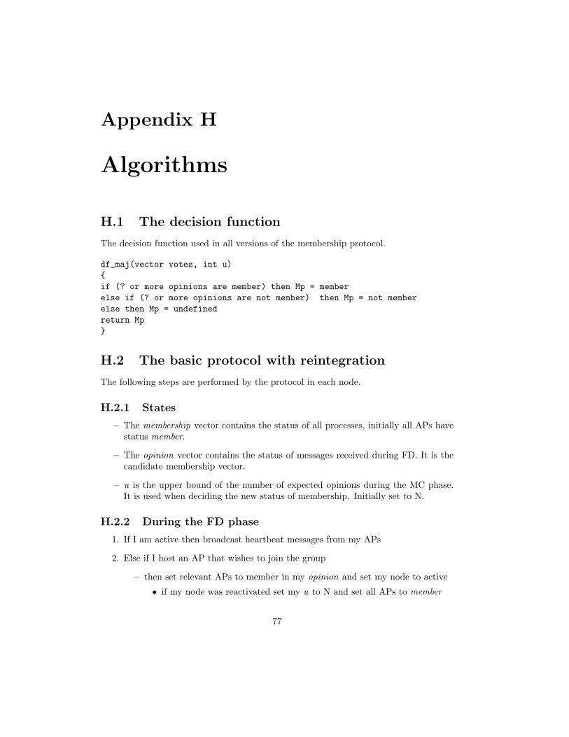
Appendix H
Algorithms
H.1 The decision function
The decision function used in all versions of the membership protocol.
df_maj(vector votes, int u)
{
if (? or more opinions are member) then Mp = member
else if (? or more opinions are not member) then Mp = not member
else then Mp = undefined
return Mp
}
H.2 The basic protocol with reintegration
The following steps are performed by the protocol in each node.
H.2.1 States
– The membership vector contains the status of all processes, initially all APs havestatus member.
– The opinion vector contains the status of messages received during FD. It is thecandidate membership vector.
– u is the upper bound of the number of expected opinions during the MC phase.It is used when deciding the new status of membership. Initially set to N.
H.2.2 During the FD phase
1. If I am active then broadcast heartbeat messages from my APs
2. Else if I host an AP that wishes to join the group
– then set relevant APs to member in my opinion and set my node to active
• if my node was reactivated set my u to N and set all APs to member
77

78 Chapter H. Algorithms
– Broadcast join-request message for joining AP
3. Observe the heartbeat messages from APs that I consider to be members
– Take note in my opinion vector
4. On reception of join-request message
– set joining AP to member
H.2.3 During the MC phase
1. Empty opinionmatrix
2. Broadcast opinionid and my u to all nodes
3. If an incoming opinion and u belongs to an active node, take note in opinionmatrixand note u
4. If it belongs to a reactivating node, take note in joinopinionmatrix and note u
H.2.4 During the MD phase
1. Get decision function result concerning each AP. Perform dfresult = dfmaj(opinioncol,u), column by column of opinion matrix. and with minimum of all received u
2. if for any AP dfresult
(a) is undefined
– then set my node to not active
(b) differs from my opinion and I am active
– then set my node to not active
(c) is not a subset of my opinion and I am joining
– then set my node to not active
(d) is not member for an AP that I host
– set my opinion about AP to not member
(e) if I do not host any member APs
– then set my node to not active
3. If any active node sent an opinion that differs from dfresult or if any reactivatingnode sent an opinion that is not a superset of dfresult then set all APs hosted bythat node to not
4. set my u to the number of active nodes in my opinion
5. if an active nodes did not broadcast an opinion during MC
– then set to not member all APs hosted on that node
6. if I do not host any member APs then set my node to not active
7. set my new membership = my opinion
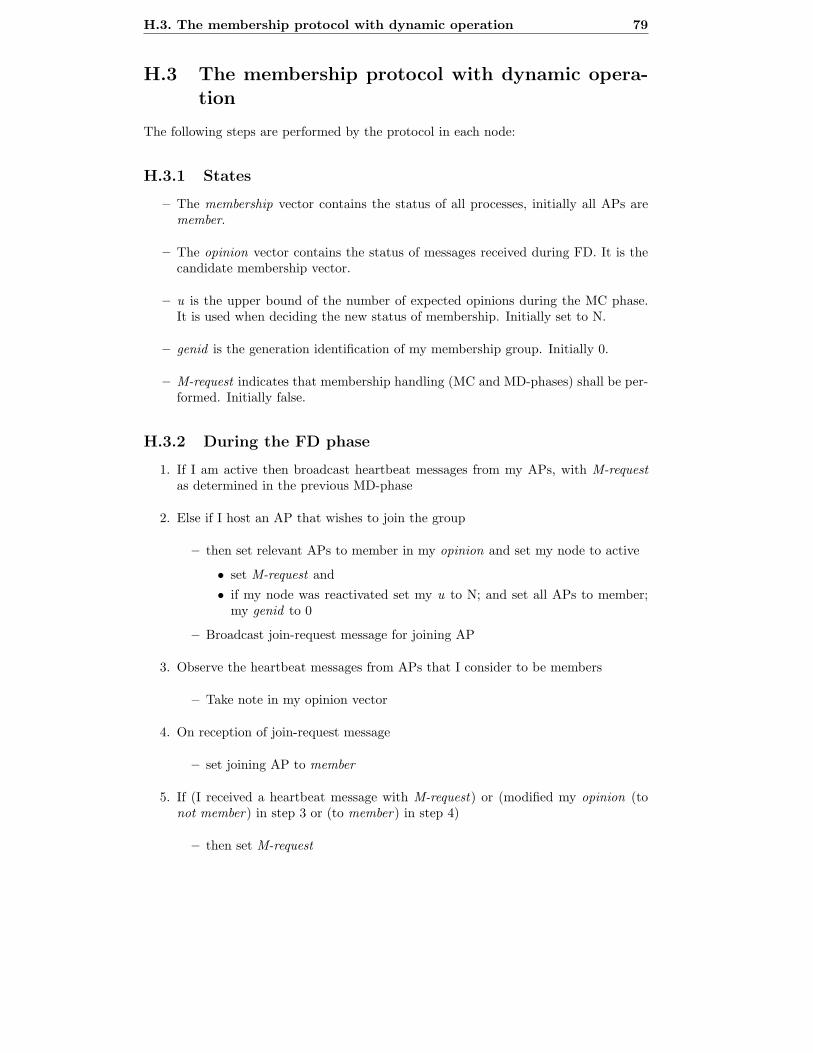
H.3. The membership protocol with dynamic operation 79
H.3 The membership protocol with dynamic opera-
tion
The following steps are performed by the protocol in each node:
H.3.1 States
– The membership vector contains the status of all processes, initially all APs aremember.
– The opinion vector contains the status of messages received during FD. It is thecandidate membership vector.
– u is the upper bound of the number of expected opinions during the MC phase.It is used when deciding the new status of membership. Initially set to N.
– genid is the generation identification of my membership group. Initially 0.
– M-request indicates that membership handling (MC and MD-phases) shall be per-formed. Initially false.
H.3.2 During the FD phase
1. If I am active then broadcast heartbeat messages from my APs, with M-requestas determined in the previous MD-phase
2. Else if I host an AP that wishes to join the group
– then set relevant APs to member in my opinion and set my node to active
• set M-request and
• if my node was reactivated set my u to N; and set all APs to member;my genid to 0
– Broadcast join-request message for joining AP
3. Observe the heartbeat messages from APs that I consider to be members
– Take note in my opinion vector
4. On reception of join-request message
– set joining AP to member
5. If (I received a heartbeat message with M-request) or (modified my opinion (tonot member) in step 3 or (to member) in step 4)
– then set M-request
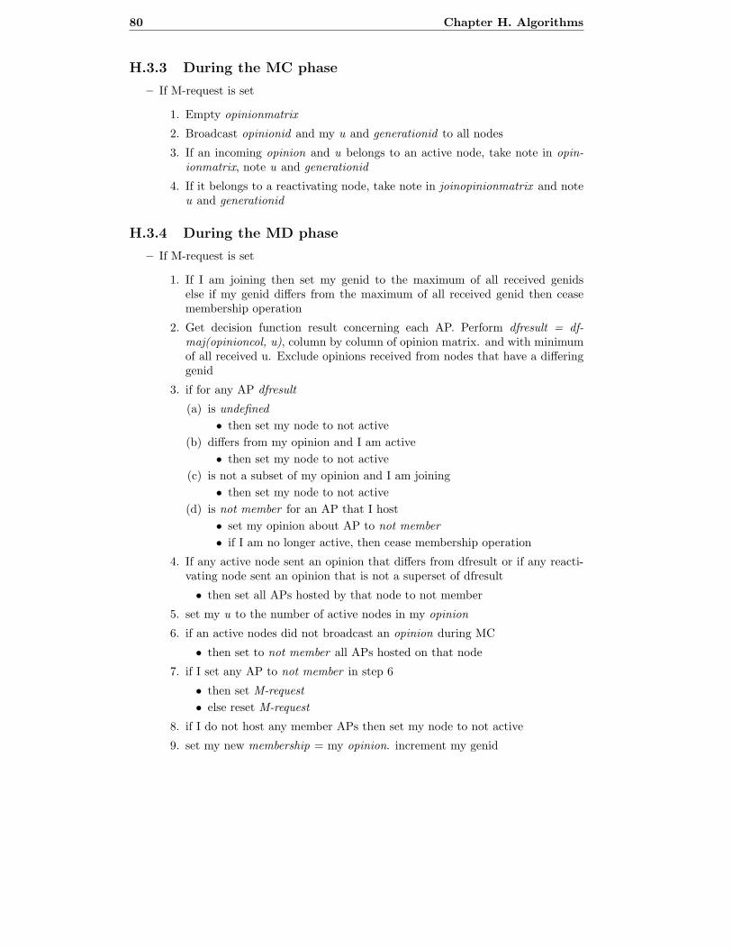
80 Chapter H. Algorithms
H.3.3 During the MC phase
– If M-request is set
1. Empty opinionmatrix
2. Broadcast opinionid and my u and generationid to all nodes
3. If an incoming opinion and u belongs to an active node, take note in opin-ionmatrix, note u and generationid
4. If it belongs to a reactivating node, take note in joinopinionmatrix and noteu and generationid
H.3.4 During the MD phase
– If M-request is set
1. If I am joining then set my genid to the maximum of all received genidselse if my genid differs from the maximum of all received genid then ceasemembership operation
2. Get decision function result concerning each AP. Perform dfresult = df-maj(opinioncol, u), column by column of opinion matrix. and with minimumof all received u. Exclude opinions received from nodes that have a differinggenid
3. if for any AP dfresult
(a) is undefined
• then set my node to not active
(b) differs from my opinion and I am active
• then set my node to not active
(c) is not a subset of my opinion and I am joining
• then set my node to not active
(d) is not member for an AP that I host
• set my opinion about AP to not member
• if I am no longer active, then cease membership operation
4. If any active node sent an opinion that differs from dfresult or if any reacti-vating node sent an opinion that is not a superset of dfresult
• then set all APs hosted by that node to not member
5. set my u to the number of active nodes in my opinion
6. if an active nodes did not broadcast an opinion during MC
• then set to not member all APs hosted on that node
7. if I set any AP to not member in step 6
• then set M-request
• else reset M-request
8. if I do not host any member APs then set my node to not active
9. set my new membership = my opinion. increment my genid