an example-based procedural system for element …takeo/papers/ijiri_eg08...t ijiri, r mĕch, t...
TRANSCRIPT

EUROGRAPHICS 2008 / G. Drettakis and R. Scopigno Volume 27 (2008), Number 3 (guest editor)
submitted to EUROGRAPHICS 2008.
An Example-based Procedural System for Element Arrangement
Takashi Ijiri†, Radomír Mĕch‡, Takeo Igarashi†*, and Gavin Miller‡ †The University of Tokyo, ‡Adobe Systems Incorporated, *PRESTO JST
Abstract We present a method for synthesizing two dimensional (2D) element arrangements from an example. The main idea is to combine texture synthesis techniques based-on a local neighborhood comparison and procedural modeling systems based-on local growth. Given a user-specified reference pattern, our system analyzes neigh-borhood information of each element by constructing connectivity. Our synthesis process starts with a single seed and progressively places elements one by one by searching a reference element which has local features that are the most similar to the target place of the synthesized pattern. To support creative design activities, we introduce three types of interaction for controlling global features of the resulting pattern, namely a spray tool, a flow field tool, and a boundary tool. We also introduce a global optimization process that helps to avoid local error concentrations. We illustrate the feasibility of our method by creating several types of 2D patterns. Categories and Subject Descriptors (according to ACM CCS): I.3.7 [Computer Graphics]: Color, shading, sha-dowing, and texture. I.3.4 [Computer Graphics]: Paint Systems.
1. Introduction
We can often observe 2D arrangements of elements in ei-ther man-made or natural environments, such as tiles, wall-paper, hatching strokes, decorative arts, fabrics, flowers, honeycombs, animal fur, waves, and so on. The synthesis of arrangement patterns is not only useful for texture gen-eration and non-photorealistic rendering (NPR), but it also poses an interesting challenge in computer graphics. These arrangements have a large variation; some of them may have regular or near-regular features throughout, others are not locally regular but they distribute irregular features uniformly (irregular uniform). To synthesize the arrange-
ment patterns, the system has to preserve local spatial rela-tionships between elements in the global distribution.
Two different groups of methods exist for generating general texture patterns; texture synthesis and procedural modeling. Pixel based texture synthesis is not well suited to the problem of element arrangement, because not each pixel but each element is individually perceptible in the element arrangements. The spatial relationships between elements are more important than those between pixels. In contrast, procedural modeling systems deal with an element as a unit module. The system starts from an initial feature, and progressively replaces and adds modules based on local generation rules. However, procedural frameworks
(a) (f)(d)
(e)
(b)
(c)
Figure 1: Our system takes the reference arrangement input by the user and analyzes the local structure by constructing the connectivity (a). We then synthesize a larger pattern which has a similar local relationship and topology (b). The user also can specify a local growth area, an underlying flow field or a boundary (c-f). Red strokes in (d) indicate user-specified flow field strokes and blue lines in (f) are user-specified boundary lines.

T Ijiri, R Mĕch, T Igarashi, & G Miller / An Example-based Procedural System for Element Arrangements
submitted to EUROGRAPHICS 2008.
are limited to patterns, in which elements have explicit local structure such as trees. For instance, it is difficult to define the growth rules for irregular uniform arrangements.
In this paper, we present a new technique for synthesiz-ing element arrangement patterns from a user-input exam-ple. The main idea is to combine texture synthesis methods based-on a local neighborhood comparison [EL99] and procedural modeling systems based on a local growth [PL90; WZS98]. Given the reference pattern, we construct connectivity to obtain the immediate neighborhood infor-mation of each element (Figure 1a) [BBT*06]. The synthe-sis process starts with a single seed and expands the pattern outward by placing a new element one by one. In this process, we apply local neighborhood comparison; we choose a reference element whose neighborhood is the most similar to the target neighborhood of the previously synthesized pattern. Figure 1(b) shows a synthesized pat-tern, in which almost all elements are uniformly distributed but two gray blobs appear to be adjacent.
To support an intuitive synthesis process, we provide three types of interaction tools for controlling global fea-tures of the resulting pattern; a spray tool for specifying the growth area, a flow field tool for specifying an underlying flow field (Figure 1(c) and (d)), and a boundary tool for limiting growth (Figure 1(e) and (f)). We also introduce a global shape optimization of the distribution in synthesis process that helps to avoid errors’ concentrating local area and to get smooth result.
Barla et al. introduced a method to synthesize stroke pat-terns dealing with a single stroke or a cluster of strokes as a unit element [BBT*06]. The main difference between their system and our system is in the synthesis process. Their system constructs a global distribution of seeds by Lloyd’s method [Llo82] at the beginning and places synthesized strokes at the seed positions. In contrast, we place elements one-by-one, generating a global distribution gradually. We also keep a local topology of each element. This difference provides several advantages and disadvantages. One advan-tage is the ability to create a regular or near regular pattern that is difficult to be created by Lloyd’s method. We can also provide the spray and flow field tool; we think it is difficult for Barla’s method to combine these controls since their method fixes the global distribution at the beginning. One disadvantage of our approach is the difficulty of ob-taining an optimized distribution. While Barla’s system generates an optimal distribution by Lloyd’s methods, it is sometimes difficult for our system to obtain a globally optimal distribution since we grow each element locally.
In recent decades, many procedural modeling systems have been proposed for creating plants, buildings or decor-ative art design. Although they have achieved impressive results, most of them require the user to write scripts to define the local growth rules, which makes it difficult for novice users to control the resulting model. In contrast, our system tries to obtain the rules from examples. We believe that our example-based procedural modeling system pro-vides a more intuitive way to design element arrangements.
2. Related Work
In this section we briefly review representative work from procedural modeling, texture synthesis, and NPR.
Procedural modeling: Recently a lot of procedural modeling systems have been developed for different pur-poses. L-System was originally formulated by Lindenmay-er [Lin68] to simulate the growth of plants and was intro-duced to the computer graphics community later [PL90]. L-Systems have been extended to simulate a wide variety of interactions between plants and their environments [MP96; PJM94]. Wong et al. applied procedural modeling to the creation of floral ornaments [WZS98]. Procedural model-ing has been used in architectural models of cities [PM01], and buildings or facades [WWSR03; MWH*06]. While these systems have achieved impressive results, they re-quire the user to write unintuitive scripts to define rules. Deussen et al. use a predefined set of rules, represented by icons. Instead of writing a script the user connects icons together and modifies their parameters [DL99]. This sys-tem, however, still requires the user to choose rules from the predefined set and, as with any procedural system. It is often not obvious what the resulting structure will be for a given set of rules. Also, the rules are fixed and the system is suitable only for modeling plants and trees. We are more interested in an example-based system in which the user only specifies a small piece of the desired pattern.
There are researchers focusing on interactions with par-ticular types of procedural models. Esch et al. used a flow field to modify street pattern [EWMZ07]. Ijiri et al. apply free hand strokes to specify the growth direction of main axes of trees [IOI06].
Texture synthesis: Texture synthesis techniques that take an example image and generate a new texture are roughly categorized into four groups; frequency domain methods, tiling methods, pixel-based methods, and patch-based methods. i) Heeger and Bergen used frequency do-main techniques [HB95], but they can only deal with spe-cific types of textures. ii) The tiling methods are used for a fast texture synthesis [CSHD03] or a near-regular texture synthesis [LLH04]. Some researches generate large object distributions by combining Poisson disk distributions and the tiling [CSHD03; LD05]. However these methods can only create irregular uniform patterns and it is difficult for them to combine the flow field control. iii) The pixel-based approaches work with neighborhood comparisons between the example and generated (target) textures [EL99; WL00], and various extensions have been developed [Ash01; HJO*01; Tur01]. iv) The patch based approach [KSE*03], which stitches the reference image along optimal seams can generate images quickly. These pixel and patch based tech-niques achieve convincing results for more general textures. However, it is still difficult to directly apply these tech-niques to element arrangements because each element is perceived individually. The local relationship between elements is more important than that between pixels.
Non-photorealistic rendering: Stroke pattern synthesis is a popular topic in NPR field. Deussen et al. generated

T Ijiri, R Mĕch, T Igarashi, & G Miller / Example-based Procedural System for Element Arrangements
submitted to EUROGRAPHICS 2008.
stipple drawings [DHOS00], Winkenbach et al. [WS94] and Salisbury et al. [SABS94] generated a pen-and-ink effect by using stroke textures. These systems synthesized stroke patterns based on generating rules that were selected by authors or observed on traditional drawings.
Some example-based systems have been published re-cently. Hertzmann et al. presented curve analogies which learns a style of an example and modifies a target curve to have a similar style [HOCS02]. Jodoin et al. generated hatching patterns by examples [JEG*02]. They focused on a relatively simple case, in which all strokes are aligned in a linear order on a curve. Our system is particularly in-spired by stroke pattern analysis and synthesis [BBT*06] that synthesize a vector-based 2D pattern from an example by extending a texture synthesis technique (See section 1).
3. Overview
Our system takes an arrangement of input elements which we call a reference arrangement and generates a new larg-er pattern which is similar to the reference. We suppose that the reference arrangement uses symbols from a prede-fined set. Each symbol in this set has a symbol id. In addi-tion, each symbol in the reference arrangement has a unique sub-id that is used in the synthesis process to diffe-rentiate between symbols of the same id. Since our focus is on element arrangements, we do not synthesize shapes of symbols. Instead, we allow the user to introduce random noises to modify the scale, rotation, and color of each syn-thesized element so as to get a larger variation [BA06].
Given a reference pattern, we analyze local relationships
between neighboring elements by triangulating the refer-ence pattern. The synthesis process begins with placing a single seed. We iteratively replace a seed with a reference element and several new seeds, similarly to the local growth of an L-System [PL90]. In each iteration step, we also construct connectivity for new elements and seeds. Figure 2 shows an example of a single iteration step. The system first chooses a seed (a), checks its neighborhood (b), and finds a reference element which has the most similar neighborhood condition to that of the seed (c). Next the system replaces the target seed with the copy of the found reference element (d). Finally, we get copies of the neigh-boring elements of the found element (e) (f), place unpopu-lated parts of them as new seeds (g), and construct edges
(h). We also introduce a global relaxation after each growth step in order to get a smooth pattern.
In the local growth process, we introduce three different modes. 1) In the non-rotation mode the system uses the reference element without rotation. 2) In the rotation mode the system searches the best fitting reference element con-sidering the rotation, resulting in a better distribution. 3) In the flow field mode the system rotates the reference to ad-just its local coordinate to the user-specified underlying flow field direction. This allows control of the global flow of the synthesized arrangement.
To support creative design activities, we introduce three types of tools for controlling global aspects of the resulting arrangement. 1) The spray tool activates seeds under the cursor area. This tool allows the user to paint the arrange-ment pattern [IOI06; RLAD06]. Our algorithm is fast enough to return immediate feedback. 2) The flow field tool allows the user to design flow fields by drawing a set of strokes. The system uses the directions of the input strokes as constraints and interpolates 2D space by radial basis functions [EWMZ07]. 3) The boundary tool allows the user to draw a set of boundary strokes which stop the local growth.
4. Analysis
Our approach differs from those used in the texture synthe-sis that deals with pixels aligned on a grid. Our target is an element arrangement, in which elements are not supposed to be aligned. Thus, we need to consider a “spatial” neigh-borhood characteristic of each element.
To extract such a neighborhood feature, we use a similar idea to the one presented by Barla et al. [BBT*06]. Given an input reference arrangement of elements, we extract the connectivity by Delaunay triangulation. We use the center position of each element. Delaunay triangulation often generates skewed triangles around the boundary, thus we remove skewed triangles which have angles greater than 2/3*π and we keep only edges which are a part of at least one un-skewed triangle. We then register relative positions, ids, and sub-ids of immediate neighborhoods of each ele-ment. We do not use elements around the boundary of the reference arrangement, since they do not have enough neighborhood elements.
When regular or near regular arrangements are input, Delaunay triangulation often generates undesired connec-
Figure 2: An overview of the local growth process. Each circle with a symbol id is a seed. The symbol id of the white stone is A and that of the gray stone is B.
(a)
(d) (e) (f)
(b) (c)
Figure 3: The system automatically generates connectivity(b) (e) for user input reference arrangement (a) (d). The user can manually modify the topology to reconstruct underlying regularity (c) (f).
T Ijiri, R Mĕch, T Igarashi, & G Miller / An Example-based Procedural System for Element Arrangements
submitted to EUROGRAPHICS 2008.
tions. Figure 3 shows examples. In the top row, several generated edges connect blocks over one row (b). In the bottom row a near-regular arrangement is input (d); how-ever generated edges have no regularity (e). Since our syn-thesis algorithm is strongly affected by local connectivity of each element, these connections often break the regular pattern. Thus, we allow the user to correct the connection after the triangulation. The user can flip an edge by click-ing it (c) and (f). This simple interface is enough to get desired connectivity in our experience.
5. Synthesis by local growth
We begin with an element at the center of the pattern and expand it outward by placing a new element one by one based on neighborhood comparisons on the previously synthesized elements. However, our target element ar-rangements are not always supposed to have regular struc-tures as in the case of pixels in a grid. The position for placing a new element and its neighborhoods is unclear. Also, the size and orientation of each element may differ. These are major differences between the texture synthesis technique and our method. To tackle this problem, we ap-ply a procedural system that defines a local growth of seeds based on connectivity of elements [PL90]. In each growth step, we not only replace a seed with the best fitting refer-ence element, but we also place new seeds by copying the immediate neighborhood of the chosen reference element.
5.1 Seeding
The seed is a candidate position of a new element. Option-ally a seed has a symbol id associated with it. This id forces the seed to become a certain element but it could be any element of the same id from the reference arrangement.
We begin the synthesis process by placing a single seed. We sort seeds by the distance from the initial seed and choose the nearest one in each growth step. In the spray tool mode, we generate an initial seed at the cursor position when the user starts painting and grow all the seeds which are in the user-specified distance from the cursor during painting.
There are some arrangement patterns in which elements have different importance. Wong et al. [WZS98] designed floral ornament by placing the larger elements at first and filling spaces with the smaller elements later. We mimic this effect by specifying the priority of seeds based-on their symbol ids. The system only grows seeds with the highest
or same priority in their neighboring area (i.e. we define the neighboring area as a circle with the radius 5 * l, where l is the average length of the edges in the reference ar-rangement). For example, in Figure 1 (b), we specified the higher priority to the gray stones and white stones, and the lower priority to the small stones which we used as fillers only.
5.2 Finding the Best Matching Element
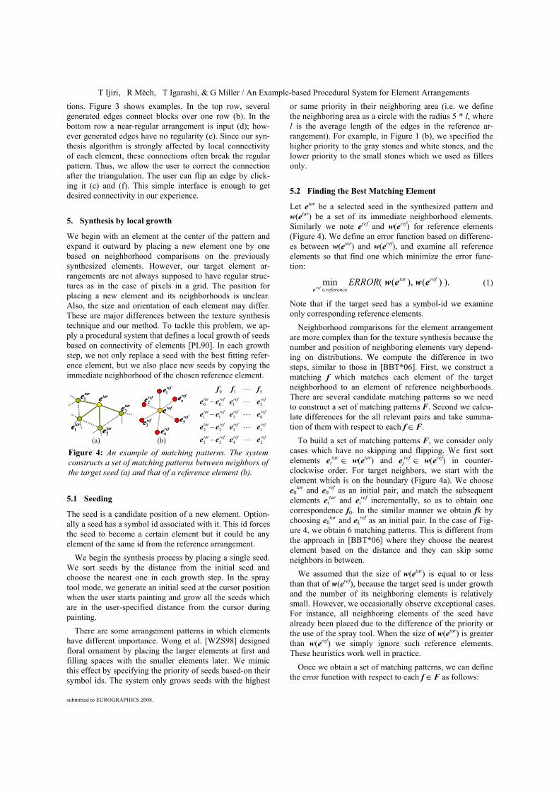
Let etar be a selected seed in the synthesized pattern and w(etar) be a set of its immediate neighborhood elements. Similarly we note eref and w(eref) for reference elements (Figure 4). We define an error function based on differenc-es between w(etar) and w(eref), and examine all reference elements so that find one which minimize the error func-tion:
).)(),((min reftar
referenceERROR
refewew
e ∈ (1)
Note that if the target seed has a symbol-id we examine only corresponding reference elements.
Neighborhood comparisons for the element arrangement are more complex than for the texture synthesis because the number and position of neighboring elements vary depend-ing on distributions. We compute the difference in two steps, similar to those in [BBT*06]. First, we construct a matching f which matches each element of the target neighborhood to an element of reference neighborhoods. There are several candidate matching patterns so we need to construct a set of matching patterns F. Second we calcu-late differences for the all relevant pairs and take summa-tion of them with respect to each f ∈F.
To build a set of matching patterns F, we consider only cases which have no skipping and flipping. We first sort elements ei
tar ∈ w(etar) and ejref ∈ w(eref) in counter-
clockwise order. For target neighbors, we start with the element which is on the boundary (Figure 4a). We choose e0
tar and e0ref as an initial pair, and match the subsequent
elements eitar and ei
ref incrementally, so as to obtain one correspondence f0. In the similar manner we obtain fk by choosing e0
tar and ekref as an initial pair. In the case of Fig-
ure 4, we obtain 6 matching patterns. This is different from the approach in [BBT*06] where they choose the nearest element based on the distance and they can skip some neighbors in between.
We assumed that the size of w(etar) is equal to or less than that of w(eref), because the target seed is under growth and the number of its neighboring elements is relatively small. However, we occasionally observe exceptional cases. For instance, all neighboring elements of the seed have already been placed due to the difference of the priority or the use of the spray tool. When the size of w(etar) is greater than w(eref) we simply ignore such reference elements. These heuristics work well in practice.
Once we obtain a set of matching patterns, we can define the error function with respect to each f ∈F as follows:
refoe
ref1e
ref3e
ref2e
ref5e
ref4e
refe
refoe
ref1e
ref3e
ref2e
ref5e
ref4e
refe
taretar1e
tar1e tar
2e
tar3e
taretar1e
tar1e tar
2e
tar3e
refrefreftar
refrefreftar
refrefreftar
refrefreftar
2433
1322
0211
5100
510
eeee
eeee
eeee
eeee
fff
L
L
L
L
L
−
−
−
−
(a) (b)
Figure 4: An example of matching patterns. The system constructs a set of matching patterns between neighbors of the target seed (a) and that of a reference element (b).

T Ijiri, R Mĕch, T Igarashi, & G Miller / Example-based Procedural System for Element Arrangements
submitted to EUROGRAPHICS 2008.
).,(),(),(
))(),((
321reftar
iji,
refj
tari
refj
tari
reftar
www eesubideeideedewewerror
f
++
=
∑∈
(2)
The d(etar, eref) is a Euclidean distance between the relative positions of etar and eref. The id(etar, eref) returns 1 if the symbol id of etar is different from that of eref , or otherwise it returns 0. These two terms measure the local spatial rela-tionship. The subid(etar, eref) is used to avoid the same ele-ment recursively appearing again and again. This function returns 1 if sub-ids of ei
tar and eref are the same, or returns 0. w1, w2, and w3 are weighting values (e.g. if the weight w1 is large the structure of the reference arrangement is better preserved in the resulting patterns.). We set w1 = 1.0, w2 = 1.0, and w3 = 100.0 to obtain the results in this paper. Fi-nally we can define the error function:
)).(),((min))(),(( reftarreftarERROR ewewerrorewewFf∈
= (3)
5.3 Rotation Modes
We introduce three modes to generate different results for different purposes; the non-rotation mode generates pat-terns that preserve the orientation of the reference neigh-borhood, the rotation mode changes the orientation of the reference neighborhood and adjusts it to the local target neighborhood, resulting in a better distribution, and the flow field mode generates patterns following the user spe-cified flow field. We achieve these effects by slightly changing the process of the finding best matching elements (Figure 5).
In the non-rotation mode, we find the best fitting element without rotating the reference pattern; we solve the error function (1) as it is. In the rotation mode, we consider the best fitting rotation when calculating the error function (2). In other words we minimize the positional difference by rotating the reference elements;
),)(,(min,∑∈ f
eRedji
refj
tari θθ
(4)
where Rθ(ejref) rotates the relative position of ej
ref. We apply the shape matching problem introduced in [MHTG05]. In the flow field mode, we consider the user specified flow field when finding the best match. We first obtain the orientation of the flow field at the target seed position. We then rotate the whole reference pattern so as to adjust its local x coordinate to the orientation. We use this rotated reference when finding the best match.
5.4 Local Growth
Now we found the best fitting reference element, and op-tionally the best fitting rotation in the rotation mode or the flow field rotation in the flow field mode.
The system first replaces the target seed with the found reference element (Figure 2d), including the symbol id and the sub-id. The system next places the new seeds by using the neighboring elements of the found element (these ele-
ments form the so called ring shape). We overlay a copy of the reference ring shape with the target seed neighborhood (Figure 2f), and then we delete every neighboring element which was paired to a target neighboring element when calculating the error function. The remaining elements will form new seeds with corresponding symbol ids (Figure 2g). Finally, we construct edges to connect the new seeds.
To avoid too dense or sparse distribution or collisions of edges, we introduce several heuristics during the local growth process (Figure 6). After obtaining new seeds, we check the neighboring area of each new seed. If we find an existing element or seed in a distance lshort from the seed, we delete the seed and connect the edge to the found object (b). We choose a half of the shortest edge length in refer-ence as lshort. We next check the angle between new edges, if the angle is less than 0.5 * original_angle, we delete the new seed and edge (c). The original_angle is the corres-ponding angle in the chosen reference ring shape (a). We also check for a collision of the edge of the new seed; if it is detected, we remove the seed and the edge (d). When constructing new edges around new seeds, we check the length of each edge. If an edge is longer than llong, we gen-erate an extra seed without a corresponding symbol id (e).
Target seed
(a) (b)Local x direction
(c)(c) (d)(d)
Flow field orientation
(e)
Flow field orientation
(e)(e)
Figure 5: The system fits a reference element (a) to a tar-get seed (b) differently depending on three rotation modes; non-rotation (c), rotation (d), and flow field mode (e).
Figure 6: The heuristic approach used to avoid undesired structures.

T Ijiri, R Mĕch, T Igarashi, & G Miller / An Example-based Procedural System for Element Arrangements
submitted to EUROGRAPHICS 2008.
We place the seed at the end of a line segment which bi-sects the corresponding angle and whose length is the aver-age of two adjacent edges (e). We define llong = 1.5 * origi-nal_length, where the original_length is the length of the corresponding edge in the ring shape (a). Then we check the edge collisions again. If a collision is detected, one or more objects must be in a triangle constructed by etar, s0 and s1, and we construct edges as shown in (f).
5.5 Relaxation
Although we place a reference element with its neighbors that have the most similar shape to the target neighbors, the error accumulates in each local growth step because the system cannot always find an optimally fitting element which makes the error value zero. Here, we introduce a relaxation process that modifies the positions of the pre-viously synthesized elements so as to keep the local feature of the synthesized pattern as similar as possible to that of the reference pattern. For each synthesized element, we adjust its ring shape to that of the corresponding reference element.
Let xi be a position of a synthesized element ei
ref, and w(xi) be a set of its neighboring positions. We also refer to the relative position of the corresponding reference ring shape as rj
i, where rji is corresponding to xj ∈ w(xi) (Figure
7(a) and (b)). We then minimize a distance between each neighbor’s positions xj and the position of the correspond-ing reference ring shape (Figure 7c):
.||)(||min)(
2∑ ∑∈
+−i j
ijij
ixwxrxx (5)
Since this representation is translation invariant, we should predetermine the position of one element in order to have a unique minimizer; we simply hold the initial element at the initial position. If there are user-specified boundaries, we constrain elements at their generated positions.
s.constraintkkk ∈= 0xx (6)
This quadratic minimization problem with linear con-straints can be solved in closed form. We apply the La-grange multiplier method. Note that there are elements which lose an edge or get an extra edge during growth. These elements no longer have same topology as the cor-responding reference element. All seeds do not have cor-responding reference elements yet. For these objects, we use their current neighboring shapes as their target ring shapes.
6. Results and Discussion
Synthesis is fast enough to return immediate feedback when the user paints using the spray tool. It took about 5 seconds to synthesize 1000 elements on a Windows XP notebook PC with Intel Core 2 Duo CPU. The bottleneck of the synthesis is the relaxation process; it took less than a second to synthesize 1000 elements without the relaxation.
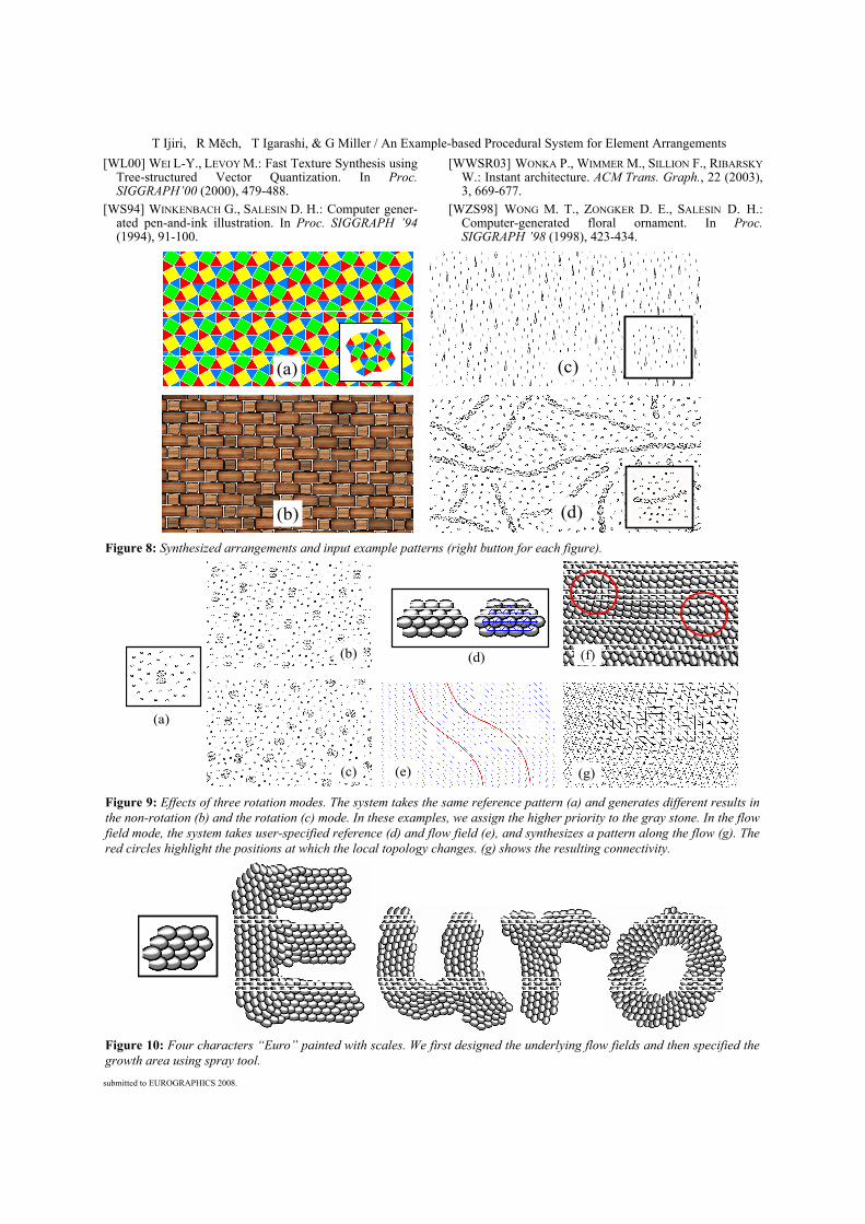
Figure 8 shows synthesized arrangements with reference patterns in the three different classes; a regular pattern (a), a near regular pattern (b), and an irregular uniform distribu-tion (c). In the case of (b), we introduced small randomness to the scale, rotation, and color of each symbol. Since our system attempts to keep local spatial relationship and to-pology between neighbors, it can cover these three classes in the same framework. Figure 8 (d) is a pattern synthe-sized by the rotation mode. This example indicates that our system successfully synthesizes a pattern in which gray stones are linked each other in rows.
Figure 9 illustrates different effects of three rotation modes. The system takes the same input example (a) and generates different results in non-rotation (b) and rotation (c) mode. In both case, two gray stones appear close to each other. While an orientation of each two stones is re-tained in the non-rotation mode, it is locally rotated in the rotation mode. The user can also control the arrangements by specifying underlying flow fields. When the user draws strokes by using the flow field tool (red curves in (e)), the system generates flow fields along to the strokes (e). The system then takes this flow fields as well as a reference arrangement (d), and it synthesizes a new pattern (f) in which scales are aligned along to the flow. Our system can change the topology to keep the uniform distribution. Two scales at which topology changes happen are highlighted by red circles (f). We show the resulting connectivity in (g).
Finally, we show results created by using three UI tools. In Figure 1 (d), we control the orientation of feathers by using the flow field tool and the growth area using the spray tool. In Figure 1 (f), we limit the growth area of the blocks by the boundary tool. We also painted four charac-ters “Euro” with an arrangement pattern by using the spray tool and flow field tool in Figure 10. In these feathers and scales examples, we arranged 3D objects which have a rounded shape and are slightly slanted, so that they natural-ly express an overlapping effect. These effects are difficult to create with a 2D vector based approach [BBT*06] be-cause it is required to specify the rendering order of ele-ments explicitly. We also have a capability to modify the local orientation or size of each element after obtaining the arrangement. This type of control is difficult for pixel based texture synthesis.
7. Conclusion and Future Work
We presented a new system for synthesizing 2D element arrangements by combining non-parametric texture synthe-sis techniques based on local neighborhood comparison and procedural modeling systems based on local growth. Our
Oijr
(b) (c)(a)
ixjx
(a)
ixjx
Figure 7: We fit an immediate neighborhood shape of each vertex (a) to its desired shape (b). We minimize a gap between each vertex and its desired position (c).

T Ijiri, R Mĕch, T Igarashi, & G Miller / Example-based Procedural System for Element Arrangements
submitted to EUROGRAPHICS 2008.
system takes a user-input reference arrangement, analyses local relationship between reference elements by construct-ing connectivity and synthesizes a larger pattern by locally growing a seed one by one. Since we attempt to keep the connectivity (i.e. topology) between neighboring elements, our system can generate various regular patterns and irre-gular uniform patterns. To support creative design activities, we present three UI tools which allow control of global features of the synthesis. We also introduce the relaxation process in order to adjust a ring shape of each synthesized element to be closer to that of the corresponding reference element.
Our current system considers only immediate neighbor-hoods, so we would like to extend our matching function to handle more than 1-ring elements in the future. While our flow field mode generates fine results with relatively sim-ple flow fields, if complicated flow fields containing sever-al peaks or edge lines are given, the system often fails to keep the local topology at the peaks or the edges and breaks local spatial relationships. Another limitation is local error concentration. Even if we introduce the relaxa-tion, our synthesis algorithm is based on local best match-ing, thus it is difficult to obtain globally optimized results. We believe that this problem can be solved by hierarchical representation introduced in texture synthesis frameworks [WL00; Tur01]. Future work might include more compli-cated patterns such as tree structures [PL90; WZS98] or 2D arrangements which vary the scaling of each element.
Finally we would like to emphasize that our approach is one of the first trials to combine the example based system and procedural modeling system. We hope that our tech-nique could be a first step towards an answer the problem of inverse procedural modeling, which is one of the biggest problems in procedural modeling research.
References
[Ash01] ASHIKHMIN, M.: Synthesizing Natural Textures. In Proc. the Symposium on Interactive 3D Graphics 2001, 217-226.
[BA06] BAXTER W., ANJYO K.: Latent Doodle Space. Com-puter Graphics Forum, 25 (2006), 3, 477-485.
[BBT*06] BARLA P., BRESLAV S., THOLLOT J., SILLION F., MARKOSIAN L.: Stroke Pattern Analysis and Synthesis. Computer Graphics Forum, 25 (2006), 3, 663-671.
[CSHD03] COHEN, M. F., SHADE, J., HILLER, S., DEUSSEN, O.: Wang tiles for image and texture generation. ACM Trans. Graph., 22(2003), 3, 287-294.
[DHOS00] DEUSSEN O., HILLER S., VAN OVERVELD C., STROTHOTTE T.: Floating points: A method for compu-ting stipple drawings. Computer Graphics Forum, 19 (2000), 3, 40-51.
[DL99] DEUSSEN O. AND LINTERMANN, B.: Interactive Modeling of Plants. IEEE Computer Graphics and Ap-plications, 19 (1999), 1, 56-65.
[EL99] EFROS A. A., LEUNG T. K.: Texture synthesis by nonparametric sampling. In IEEE Int. Conf. on Comput-er Vision (1999), 1033-1038.
[EWMZ07] ESCH G., WONKA P., MÜLLER P., ZHANG E.: Interactive procedural street modeling, SIGGRAPH 2007 Sketches.
[HB95] HEEGER, D. J., BERGEN, J. R.: Pyramid-based tex-ture analysis and synthesis. In Proc. SIGGRAPH ’95 (1995), 229-238.
[HJO*01] HERTZMANN, A., JACOBS, C. E., OLIVER, N., CURLESS, B., SALESIN, D. H.: Image Analogies. In Proc. SIGGRAPH ’01(2001), 327-340.
[HOCS02] HERTZMANN A., OLIVER N., CURLESS B., SEITZ S. M.: Curve analogies. In Proc. the 13th Eurographics Workshop on Rendering(2002), 233-246.
[IOI06] IJIRI T., OWADA S., IGARASHI T.: The sketch L-System: global control of tree modeling using free-form strokes. In Proc. SmartGraphics 2006, 138-146.
[JEG*02] JODOIN P. M., EPSTEIN E., GRANGER-PICHE M., OSTROMOUKHOV V.: Hatching by example: a statistical approach. In Proc. NPAR 2002, 29-36.
[KSE*03] KWATRA, V., SCHODL, A., ESSA, I., TURK, G., BOBICK, A.: Graphcut textures: Image and video synthe-sis using graph cuts. ACM Trans. Graph. 22 (2003), 3, 277-286.
[Lin68] LINDENMAYER A.: Mathematical models for cellu-lar interactions in development, I & II. Journal of Theo-retical Biology 18, 3 (1968), 280-315.
[Llo82] LLOYD S. P.: Least squares quantization in pcm. IEEE Trans. Information Theory 28, 2(1982), 129-137.
[LD05] LAGAE A., DUTRE P.: A procedural object distribu-tion function. ACM Trans. Graph., 24(2005), 4, 1442-1461.
[LLH04] LIU Y., LIN W. C., HAYS J. H.: Near regular tex-ture analysis and manipulation. ACM Trans. Graph., 23(2004), 3, 368-376.
[MHTG05] MULLER M., HEIDELBERGER B., TESCHNER M., GROSS M.: Meshless deformations based on shape matching. ACM Trans. Graph., 24(2005), 3, 471-478.
[MP96] MĚCH R., PRUSINKIEWICZ P.: Visual models of plants interacting with their environment. In Proc. SIGGRH ’96(1996), 397-410.
[MWH*06] MULLER P., WONKA, P., HAEGLER, S., ULMER, A., GOOL, L. V.: Procedural modeling of buildings. ACM Trans. Graph., 25(2006) 3, 614-623.
[PJM94] PRUSINKIEWICZ P., JAMES M., MĚCH R.: Synthetic topiary. In Proc. SIGGRAPH ’94(1994), 351-358.
[PL90] Prusinkiewicz P., Lindenmayer A.: The Algorithmic Beauty of Plants. Springer–Verlag, New York, 1990. With J. S. Hanan, F. D. Fracchia, D. R. Fowler, M. J. M. de Boer, and L. Mercer.
[PM01] PARISH Y. I. H., MULLER P.: Procedural modeling of cities. In Proc. SIGGRAPH ‘01(2001), 301-308.
[RLAD06] RITTER L., LI W., AGRAWALA M., CURLESS B., SALESIN D.: Painting with Texture. In Proc. 17th Euro-graphics Symposium on Rendering (2006), 371-376.
[SABS94] SALISBURY M. P., ANDERSON S. E., BARZEL R., SALESIN D. H.: Interactive pen-and-ink illustration. In Proc. SIGGRAPH ’94(1994), 101-108.
[Tur01] TURK G.: Texture Synthesis on Surfaces. In Proc. SIGGRAPH ’01(2001), 347-354.
T Ijiri, R Mĕch, T Igarashi, & G Miller / An Example-based Procedural System for Element Arrangements
submitted to EUROGRAPHICS 2008.
[WL00] WEI L-Y., LEVOY M.: Fast Texture Synthesis using Tree-structured Vector Quantization. In Proc. SIGGRAPH’00 (2000), 479-488.
[WS94] WINKENBACH G., SALESIN D. H.: Computer gener-ated pen-and-ink illustration. In Proc. SIGGRAPH ’94 (1994), 91-100.
[WWSR03] WONKA P., WIMMER M., SILLION F., RIBARSKY W.: Instant architecture. ACM Trans. Graph., 22 (2003), 3, 669-677.
[WZS98] WONG M. T., ZONGKER D. E., SALESIN D. H.: Computer-generated floral ornament. In Proc. SIGGRAPH ’98 (1998), 423-434.
(c)(c)(a)(a)
(b)(b) (d)(d)
Figure 8: Synthesized arrangements and input example patterns (right button for each figure).
(a)
(e)
(d)(b)
(c) (g)
(f)
Figure 9: Effects of three rotation modes. The system takes the same reference pattern (a) and generates different results in the non-rotation (b) and the rotation (c) mode. In these examples, we assign the higher priority to the gray stone. In the flow field mode, the system takes user-specified reference (d) and flow field (e), and synthesizes a pattern along the flow (g). The red circles highlight the positions at which the local topology changes. (g) shows the resulting connectivity.
Figure 10: Four characters “Euro” painted with scales. We first designed the underlying flow fields and then specified the growth area using spray tool.