an evolutionary method to vision-based self-localization...
TRANSCRIPT

Scientia Iranica B (2015) 22(6), 2071{2080
Sharif University of TechnologyScientia Iranica
Transactions B: Mechanical Engineeringwww.scientiairanica.com
An evolutionary method to vision-basedself-localization for soccer robots
C.-Y. Chen� and C.-C. Ko
Department of Information and Telecommunications Engineering, Ming Chuan University, Taoyuan, Taiwan, ROC.
Received 22 May 2014; accepted 28 April 2015
KEYWORDSEvolutionaryalgorithm;Omnidirectionalvision system;Soccer robot;Self-localization;Path planning.
Abstract. In this paper, a method using an evolutionary algorithm to automaticallyset-up the color-feature model of an omnidirectional vision system will be introduced. Thementioned method, in addition to avoiding the issue of over-reliance on lighting conditionswhen the soccer robot is performing image processing, can also very e�ectively speed up theparameter setup procedure of the robot vision system. Hence, when the robot is movingin the soccer �eld, it can �nish target object detection and self-localization in real time. Inorder to verify the e�ectiveness of the mentioned method, tests have been conducted underdi�erent bad lighting conditions, and the experimental results show that the soccer robotcan always set up the parameters of the vision system. It can also set up the color-featuremodel that is applicable to the operational environment at that moment and detect targetobjects such as goals and the �eld. Meanwhile, through relative location between detectedtarget objects and the robot, self-localization and path planning can be �nished.© 2015 Sharif University of Technology. All rights reserved.
1. Introduction
The design of intelligent robots has become one ofthe developmental focuses of international academicresearch and industry application in recent years,and some advanced industrialized countries have eventreated robot competitions as a strategic means topromote domestic creativity teaching. Currently, thereare two robot-soccer associations, RoboCup and FIRA,devoting to the promotion of robot soccer games [1,2],and each year, international cup robot soccer gamesand international forums are held regularly for theexchange of research results. The robot soccer gameis interdisciplinary integrated research work coveringarti�cial intelligence, automatic control, image process-ing, mechanism design, sensor systems and electroniccommunication. The holding of robot soccer games caninternationally promote and stimulate the exchange
*. Corresponding author. Tel.: +886-3-350-7001#3737;Fax: +886-3-359-3879E-mail address: [email protected] (C.-Y. Chen)
and development of technology related to arti�cialintelligence, the strength design of mechanisms andmulti-sensor system applications. In order to allowrobots the means to play soccer in the soccer �eld in-dependently, from a practical design aspect, the robotmust be able to, from image analysis results, decide themovement direction of the robot body. Meanwhile, itmust be able to implement functions such as path plan-ning, avoiding obstacles and dynamic object tracking.Moreover, cooperative strategies among several soccerrobots, such as assisting, defending and ball passing,should also be considered. The design process can notonly e�ectively enhance the students' implementationcapability, but can also help the incubation of creativityand a collaborative spirit. Hence, its importance hasreceived more and more attention from both academiaand industry.
The design of a vision system is core technologyfor a robot. Although academia has spent severaldecades studying human vision systems, the relatedfunctions and principles of the human eye still cannotbe fully understood. Hence, the use of machine vision

2072 C.-Y. Chen and C.-C. Ko/Scientia Iranica, Transactions B: Mechanical Engineering 22 (2015) 2071{2080
to simulate human vision is a pretty tough challenge.After a robot has used a vision system to complete theimage analysis of the peripheral environment, based onrecognition and judgment, the robot can then make acorrect response. For video input amounts of 30 imagesper second, if massive features need to be found andcompared for each image, it is not di�cult to imaginethat there is a huge amount of image and operationaldata hidden behind the vision system of the robot. Notonly this, during the processing process, if situationssuch as optical source conditions or vision angleschange, or if the sudden disappearance or emergence ofobjects in the environment are encountered, a exibleresponse is needed. That is, when the visional systemof a robot is facing environmental changes, its imageprocessing must be very robust. Only when the robotcan process environmental uncertainty correctly can itsutility goal be reached.
In the �eld of the robot soccer game of theFIRA association, the appearance of target objects isdistinguished by speci�c colors. Here, the robot isblack, the soccer �eld is a green background paintedwith white lines, the soccer ball is orange, and the gatesat both sides of the �eld are, respectively, yellow andblue. Therefore, if the robot is to have the capabilityof identifying the target object in the soccer �eld, thesimplest method is to use the color information of thetarget object as a feature. After the image is acquiredby the omnidirectional camera at the top of the robot,the image information will be transmitted throughthe YUV color system, and then converted into theRGB color system to be used by the subsequent imageanalysis module. Digital images, using the RGB colorsystem, could be easily and signi�cantly a�ected byoptical beam changes. Hence, before performing imageanalysis, we will �rst use the look-up table methodto perform color space transformation from RGB toHSV, so as to reduce the in uence of brightness onthe color of the object [3]. After completing imagetransformation, we need to set up the upper and lowerlimit values of the color of each target object, and set upthe color-feature model. Using the setup color featuremodel, we can then detect and extract target objects,such as balls and gates, from di�erent input images.The process is shown in Figure 1.
Figure 1. The setup process of the color-feature model ofthe FIRA robot system.
In the current architecture of FIRA medium-sized soccer robots, the participant must, based on thelighting condition of the operation site, manually setup, one by one, the color range value of each robot onall the target objects in the soccer �eld, in order toset up a color-feature model that can meet the needs.Such a model construction method, based on the trialand error method, is very tedious and time-consuming.In fact, in the current rules, even in the indoor game,the luminance of the game site still allows a di�erencewithin 300 lumens. Hence, the light source within theenvironment of the game site is not uniform and consis-tent. As the robot moves in the soccer �eld constantly,the gray levels and hues of the omnidirectional imageacquired will change accordingly, too. Hence, over-simpli�ed video processing architecture cannot satisfythe current situation. It is estimated that severalyears in the future, the game of a medium-sized soccerrobot group will be all in natural light instead of astable indoor lighting source, and this will bring morestringent challenges to the vision system design of therobot.
The evolutionary computing technique is an op-timal solution search mechanism that is constructedbased on a biological evolutionary concept. All kindsof di�cult combinatorial optimization problems can besolved by its use. After almost 30 years of e�ort, evo-lutionary computing has its own unique research �eld,which includes Evolution Strategy (ES), EvolutionaryProgramming (EP), Genetic Algorithm (GA), Simu-lated Annealing (SA), PSO [4], and Ant Colony Opti-mization (ACO). All these computing techniques haverespective advantages and disadvantages: Take GA, forexample, it has advantages such as a parallel multi-point search and easy integration with other methods.However, the convergence speed at solving problemsis not so good. Although SA has better convergencecharacteristics, parallel implementation is di�cult [5].Some scholars try to use the swarm intelligent behaviorof natural phenomena to develop a hybrid optimizationalgorithm [6,7], so that complementary e�ects, amongdi�erent methods, can be achieved. PSO, among lots ofalgorithms, has characteristics such as less parametersettings, robustness and high convergence speed [8].Currently, in academia, much research has applied PSOin image processing, with larger amounts of computingdata, in pattern recognition or video processing [9-12],and all results prove that it has a good performance oncomplicated problems.
In the present paper, we have presented a de-sign method for a robot evolutionary vision systembased on PSO, which allows the robot to, before theoperation, follow the light source environment, andmake automatic evolutions for the needed color-featuremodel. Hence, it can replace the traditional time-consuming method based on trial and error for all

C.-Y. Chen and C.-C. Ko/Scientia Iranica, Transactions B: Mechanical Engineering 22 (2015) 2071{2080 2073
Figure 2. FIRA medium-sized soccer robot: (a) Hardware architecture; and (b) actual appearance.
kinds of parameter setup. Eventually, the robot canbe more robust to cope with future ever complicatedand changing game environments.
2. Introduction of FIRA medium-sized soccerrobot system
The architecture of FIRA medium-sized soccer robotscan be divided into a top layer omnidirectional visionsystem, a motor drive module and a bottom layer om-nidirectional moving mechanism. Figure 2(a) and (b)show its appearance.
2.1. Omnidirectional vision systemA Medium-sized soccer robot uses an omnidirectionalcamera to construct a vision system to acquire imagesin the peripheral environment. The output NTSCanalog signal, after A/D conversion into a digital signaland after image processing and analysis, will be able todisplay the information of the environment. Robotsequipped with omnidirectional cameras, during thegame process, do not need to rotate the camera specif-ically to know the peripheral images of 360 degrees,which e�ectively enhances its detection capability andchange-coping speed within the environment. Thehorizontal vision of an omnidirectional camera is 360degrees, and the vertical vision is -10 degrees to 55degrees, which are shown in Figure 3(a). Since anomnidirectional mirror has its image formed throughoptical re ection of the peripheral image, which leadsto serious distortion on the actually observed image,its image formation is of concentric divergence, and anobject that has longer distance from the robot bodyitself will receive more serious distortion, as shown inFigure 3(b).
Figure 3. Omnidirectional visional system: (a)Appearance of omnidirectional visional camera; and (b)omnidirectional image.
2.2. Motor drive module and omnidirectionalmoving mechanism
This study has used an Altera Nios II Developmentboard to construct a motor drive module to controlthe rotation of the motor. The four-wheeled omni-directional chassis structure allows the robot to make360 degrees omnidirectional movements on the ground.Thus, the mobility of the robot is e�ectively enhanced.Figure 4 shows the relationship between the four-wheeled chassis design structure and velocity vectors,and the four-wheeled movement equation is representedin Eq. (1) [13-15]:2664v1
v2v3v4
3775=
2664R_�1
R _�2
R _�3
R _�4
3775=
2664� sin(�) cos(�) L� sin(�) � cos(�) Lsin(�) � cos(�) Lsin(�) cos(�) L
377524 _xm_ym_�
35 ;(1)
where vi is the moving velocity of the ith wheel; _xmis the moving speed of the robot on the xm axis; _ymis the moving speed of the robot on the ym axis; _'

2074 C.-Y. Chen and C.-C. Ko/Scientia Iranica, Transactions B: Mechanical Engineering 22 (2015) 2071{2080
Figure 4. The correlation between the four-wheeledomnidirectional chassis structure and velocity vectors.
is the rotational angular velocity of the robot; L isthe distance from the omnidirectional wheel to theomnidirectional movement robot chassis center O; Ris the radii of the omnidirectional wheel; and _�i is therotational angular speed of the ith wheel.
3. Using PSO to construct the vision system
3.1. Particle swarm optimizationSince Kenney and Eberhart developed the PSO in 1995,it is regarded as an evolutionary computation techniqueto solve many optimal problems. Based on imitationof simpli�ed social models, PSO can be considereda swarm-based learning scheme, like �sh schoolingand bird ocking. According to the natural foragingbehavior of bird ocking, birds �nd food by ocking(not by each individual). In the PSO learning process,each single solution is a bird, referred to as a particle.This PSO learning algorithm simulates the swarm-likebehavior of natural creatures. The individual particles y gradually towards the positions of their own andtheir neighbors' best previous experiences in a hugesearch space. From this study, it shows that thePSO is given more opportunity to \ y" into desiredareas to get better solutions. Therefore, PSO candiscover reasonable solutions much faster than otherevolutionary algorithms. Like GA, the PSO needsto de�ne a proper �tness function that evaluates thequality of every particle's position. The position,called the global best (gbest), is the one which hasthe highest �tness value among the entire swarm.The location, called the personal best (pbest), is theone which has each particle's best experience. Basedon every particle's momentum, and the in uence ofboth personal best (pbest) and global best (gbest)solutions, every particle adjusts its velocity vector ateach iteration. The PSO learning formula is described
as follows [4,9]:
Vi;m(t+ 1) = �:Vi;m(t) + c1 � rand( )
� (pbesti;m(t)�Xi;m(t)) + c2 � rand( )
� (gbestm(t)�Xi;m(t)); (2)
Xi;m(t+ 1) = Xi;m(t) + Vi;m(t+ 1); (3)
where m is the dimensional number; i denotes the ithparticle in the population; V is the velocity vector; X isthe position vector; � is the inertia factor; and c1 and c2are the cognitive and social learning rates, respectively.Note that these two rates control the relative in uenceof the memory of particles and the neighborhood.
3.2. Using PSO to automatically set up acolor-feature model
As shown in Figure 1, soccer robot uses the colorinformation of the target object to recognize the object.Hence, before each driving of the robot, we have tofollow the lighting conditions at that time within theHSV color space and aim at each target object to set upa suitable color-feature model. The HSV color systemis formed by information, such as Hue, Saturation andValue, and its advantage is in separating the brightnesscomponent from the color information. Hence, thein uences of lighting change can be reduced. Whenthese three basic attributes are used to describe thecolor, it can better �t human sensory recognition,compared to the RGB color system. After completingconstruction of the color feature model, the soccerrobot can use it to analyze the image, and the speci�ctarget object meeting the threshold condition can thenbe recognized.
In this paper, we have used PSO to realize anevolutionary vision system, so that the robot can followthe lighting condition of the environment it is in tomake automatic evolutions of the color-feature modelit needs. The architecture is shown in Figure 5. Beforethe start of a game, when both the ball and the robotare settled at �xed positions, at this moment, the soccerrobot can, through the PSO algorithm, set up theneeded color-feature model to complete the parametersetup procedure before the game.
3.2.1. Encoding of the particleTo achieve the goal of using the PSO algorithm tomake the automatic evolution of a color-feature model,we �rst have to generate an initial population, andthe encoding value of each particle in the populationrepresents the solution parameters of a di�erent color-feature model. Evaluation of the capability to success-fully extract the target objects is its adaptability tothe environment. The encoding form of the particle isshown in Figure 6. According to practical operational

C.-Y. Chen and C.-C. Ko/Scientia Iranica, Transactions B: Mechanical Engineering 22 (2015) 2071{2080 2075
Figure 5. An evolutionary visional system architecture diagram based on the PSO algorithm.
Figure 6. The encoding form of particle.
experience, we have found that under most conditions,when the upper limit values of parameters, such as thesaturation and value of the color-feature model, are�xed at maximal values (i.e. Smax = 100, Vmax = 100),it facilitate extraction of the target objects. Therefore,in this research, we have set up the encoding values ofthe particles as the set of the upper and lower limit val-ues of Hue, and the lower threshold values of saturationand value; that is, X = fHmax;Hmin; Smin; Vming, and0 5 H 5 360, 0 5 Smin < 100, and 0 5 Vmin < 100.
3.2.2. Fitness function evaluationThe �tness function, in the PSO algorithm, is anindex used to assess the �tness of a particle to itsenvironment. In this paper, we have used the targetobject image extracted from an optimal color-featuremodel using experience value as a template. Then, it
is compared, one by one, to the target object imageextracted by each particle in the PSO population, tocalculate the similarity between each other. Hence,the corresponding �tness value can then be obtained.Eqs. (4) and (5) have explained the method, usingimplementation of the operation of image subtractionto assess the di�erence of two target object images:
d(fTemplate; fobtained)
=MXi=1
NXj=1
jfTemplate(i; j)� fobtained(i; j)j ; (4)
Fitness =1
d(fTemplate; fobtained) + eps; (5)
where \eps" represents an extremely small value, and

2076 C.-Y. Chen and C.-C. Ko/Scientia Iranica, Transactions B: Mechanical Engineering 22 (2015) 2071{2080
fTemplate is the standard extracted result of the targetobjects.
The color-feature model of the soccer robot shouldbe set up completely, according to the lighting condi-tions, before the game. After the ball and the soccerrobot are settled, the robot will then start to performthe automatic setup procedure of the color-featuremodel. In the setup method, each particle in the PSOalgorithm represents a di�erent color-feature parameterset. Then, the parameter set, aiming at the acquiredimage, can obtain the extracted result, fobtained, forthe target object. This result will then be compared tothe standard extracted result, fTemplate, which is storedin advance in the robot. Then, an evaluation value ofsuperior or inferior performance can be obtained. Afterthe �nishing of the iteration procedure, the optimalsolution can be used to obtain the applicable color-feature model under that lighting condition. Figure 7illustrates the use of the image subtraction method forassessing the �tness value of the particle. In this �gure,the encoding value of each particle corresponds to theextraction judgment condition of one set of the targetobject. After the subtraction is made between theextracted target object image and the sample image,the di�erence pixels are represented by red. When thered block is larger, it means the error is larger, hence,the particle should have a smaller �tness value. On the
contrary, when the red block is smaller, it means the�tness value is larger.
After completing all particle �tness value assess-ments, the next thing is to follow Eqs. (2) and (3)to correct the position and movement velocity of allthe particles in the population. The search directionwill, in the iterative process, gradually approach theposition of global optimum.
4. Implementation results and discussions
Figure 8(a) is an omnidirectional image obtained un-der ideal lighting conditions, and Table 1 shows theparameter values of the color-feature model setupusing trial and error. Using the extraction rules in
Table 1. The parameter values of the color-feature modelunder ideal lighting conditions.
Ball Goal (yellow) Goal (blue) Field
Hmax 24 100 244 164Hmin 343 54 153 97Smax 100 100 100 100Smin 69 55 68 68Vmax 100 100 100 100Vmin 13 23 16 18
Figure 7. The calculation of the di�erence among images to get the �tness function assessment result.
Figure 8. Omnidirectional image under ideal lighting conditions: (a) The original image; (b) the extraction result oftarget objects; and (c) the recognition result.

C.-Y. Chen and C.-C. Ko/Scientia Iranica, Transactions B: Mechanical Engineering 22 (2015) 2071{2080 2077
Figure 9. Target objects detection result after lighting conditions change: (a) Brighter lighting condition; (b) theextraction result of the target objects; and (c) the recognition result.
Figure 10. Target objects detection result after lighting conditions change: (a) Darker lighting condition; (b) theextraction result of the target objects; and (c) the recognition result.
Table 1, we can obtain the extraction results of targetobjects, such as the ball, the goals and the �eld, as inFigure 8(b). After con�rming the block position of thetarget objects, from information, such as distance andrelative angle of the center point pixel of the acquiredimage (Figure 8(c)), we can then calculate the actualdistance and relative position of the target object inthe soccer �eld.
Since the lighting conditions of the soccer �eldusually change, along with the game time or game site,usually, when the lighting conditions are changed, theoriginally setup color-feature model will have di�cultyin detecting the target object successfully. Figure 9(a)and Figure 10(a) show, under somehow brighter anddarker lighting conditions, cases when the color-featuremodel of Table 1 is used to undertake target objectdetection. It is clear that most target objects can nolonger be extracted successfully, and the results are asshown in Figure 9(b)-(c) and Figure 10(b)-(c). In theexample of Figure 9, only the ball and the �eld canbe successfully detected, and all the blue and yellowgates cannot be detected. Figure 10 is an exampleof the failed detection of a yellow gate, and the bluegate and �eld block in this case cannot all be fullyacquired.
In order to avoid the in uence of lighting condi-tion changes on the vision system of the soccer robot,and the subsequent failure of analysis of the peripheralenvironment using preset judgment conditions, in thisresearch, we have used the PSO algorithm to set up acolor-feature model dynamically. Hence, we can copewith the change in lighting conditions to perform theparameter adjustment of the model. In the experiment,
Table 2. The parameter values of the color-feature modelobtained under brighter lighting condition.
Ball Goal(yellow)
Goal(blue)
Field
Hmax 74 100 258 150
Hmin 290 36 180 95
Smax 100 100 100 100
Smin 5 58 46 43
Vmax 100 100 100 100
Vmin 86 52 41 52
we have set up the number of particles of PSO to beequal to 20, the iteration number = 50, and c1 = c2 =1:5.
After the robot and all the target objects onthe soccer �eld are placed in their �xed positions,Table 2 shows the obtained evolutionary color-featuremodel using PSO under brighter lighting conditions(Figure 11(a)). Through the extraction condition ofTable 2, we can successfully detect all the targetobjects, as shown in Figure 11(b) and (c). After com-pleting the recognition of the target objects, the soccerrobot can further use a self-localization algorithm tocon�rm the relationship, such as relative location anddistance between the target objects [16] (Figure 11(d)).Meanwhile, soccer ball shooting is implemented accord-ing to the path planning result (Figure 11(e)).
As the robot moves to di�erent locations andunder di�erent viewing angles, the image acquired bythe omnidirectional camera will change (Figure 12(a)).However, through the extraction condition of Table 2,

2078 C.-Y. Chen and C.-C. Ko/Scientia Iranica, Transactions B: Mechanical Engineering 22 (2015) 2071{2080
Figure 11. The extraction and recognition results of target objects using the color model parameters (Table 2)constructed by PSO: (a) Brighter lighting condition; (b) the extraction result of the target objects; (c) the recognitionresult; (d) the self-localization result; and (e) the path planning result.
Figure 12. The extraction and recognition results of target objects using Table 2 after robot has changed its positionduring the walking process: (a) The omnidirectional image obtained at di�erent locations; (b) the extracted result oftarget objects; (c) the recognition result; (d) the self-localization result; and (e) the path planning result.
we can still detect all the target objects, which are asshown in Figure 12(b)-(c). Figure 12(d) shows theself-localization result, and Figure 12(e) is the pathplanning result.
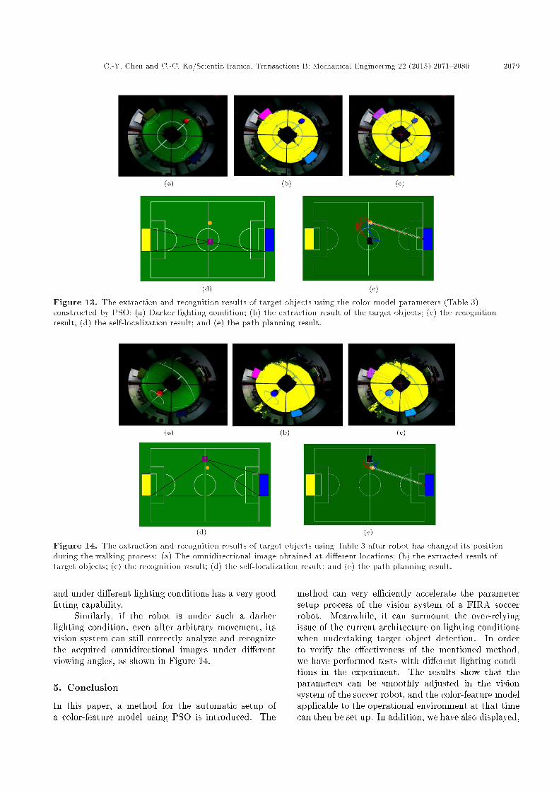
Based on the same procedures, we have con�rmedthe model construction capability of PSO under adarker environment, which is shown in Figure 13(a).The parameter values obtained from the color-featuremodel are listed in Table 3. Figure 13(b)-(e) showthe results of target object extractions, self-localizationresults, and path planning. Here, we can �nd that theevolutionary vision system constructed based on PSO,
Table 3. The parameter values of the color-feature modelobtained under brighter lighting condition.
Ball Goal(yellow)
Goal(blue)
Field
Hmax 48 110 275 143
Hmin 316 41 220 119
Smax 100 100 100 100
Smin 37 98 98 76
Vmax 100 100 100 100
Vmin 41 13 1 17
C.-Y. Chen and C.-C. Ko/Scientia Iranica, Transactions B: Mechanical Engineering 22 (2015) 2071{2080 2079
Figure 13. The extraction and recognition results of target objects using the color model parameters (Table 3)constructed by PSO: (a) Darker lighting condition; (b) the extraction result of the target objects; (c) the recognitionresult; (d) the self-localization result; and (e) the path planning result.
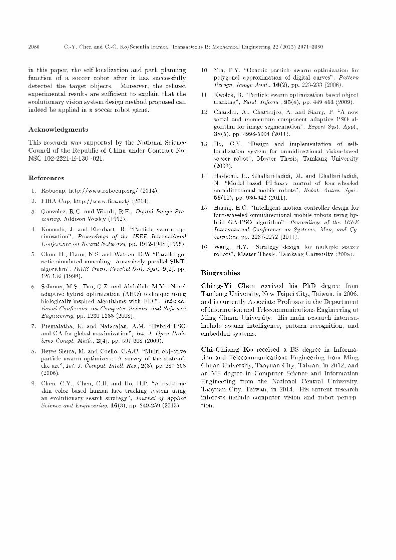
Figure 14. The extraction and recognition results of target objects using Table 3 after robot has changed its positionduring the walking process: (a) The omnidirectional image obtained at di�erent locations; (b) the extracted result oftarget objects; (c) the recognition result; (d) the self-localization result; and (e) the path planning result.
and under di�erent lighting conditions has a very good�tting capability.
Similarly, if the robot is under such a darkerlighting condition, even after arbitrary movement, itsvision system can still correctly analyze and recognizethe acquired omnidirectional images under di�erentviewing angles, as shown in Figure 14.
5. Conclusion
In this paper, a method for the automatic setup ofa color-feature model using PSO is introduced. The
method can very e�ciently accelerate the parametersetup process of the vision system of a FIRA soccerrobot. Meanwhile, it can surmount the over-relyingissue of the current architecture on lighting conditionswhen undertaking target object detection. In orderto verify the e�ectiveness of the mentioned method,we have performed tests with di�erent lighting condi-tions in the experiment. The results show that theparameters can be smoothly adjusted in the visionsystem of the soccer robot, and the color-feature modelapplicable to the operational environment at that timecan then be set up. In addition, we have also displayed,
2080 C.-Y. Chen and C.-C. Ko/Scientia Iranica, Transactions B: Mechanical Engineering 22 (2015) 2071{2080
in this paper, the self-localization and path planningfunction of a soccer robot after it has successfullydetected the target objects. Moreover, the relatedexperimental results are su�cient to explain that theevolutionary vision system design method proposed canindeed be applied in a soccer robot game.
Acknowledgments
This research was supported by the National ScienceCouncil of the Republic of China under Contract No.NSC 102-2221-E-130 -021.
References
1. Robocup, http://www.robocup.org/ (2014).
2. FIRA Cup, http://www.�ra.net/ (2014).
3. Gonzalez, R.C. and Woods, R.E., Digital Image Pro-cessing, Addison Wesley (1992).
4. Kennedy, J. and Eberhart, R. \Particle swarm op-timization", Proceedings of the IEEE InternationalConference on Neural Networks, pp. 1942-1948 (1995).
5. Chen, H., Flann, N.S. and Watson, D.W.\Parallel ge-netic simulated annealing: Amassively parallel SIMDalgorithm", IEEE Trans. Parallel Dist. Syst., 9(2), pp.126-136 (1998).
6. Soliman, M.S., Tan, G.Z. and Abdullah, M.Y. \Noveladaptive hybrid optimization (AHO) technique usingbiologically-inspired algorithms with FLC", Interna-tional Conference on Computer Science and SoftwareEngineering, pp. 1230-1233 (2008).
7. Premalatha, K. and Natarajan, A.M. \Hybrid PSOand GA for global maximization", Int. J. Open Prob-lems Compt. Math., 2(4), pp. 597-608 (2009).
8. Reyes-Sierra, M. and Coello, C.A.C. \Multi-objectiveparticle swarm optimizers: A survey of the state-of-the-art", Int. J. Comput. Intell. Res., 2(3), pp. 287-308(2006).
9. Chen, C.Y., Chen, C.H. and Ho, H.P. \A real-timeskin color based human face tracking system usingan evolutionary search strategy", Journal of AppliedScience and Engineering, 16(3), pp. 249-259 (2013).
10. Yin, P.Y. \Genetic particle swarm optimization forpolygonal approximation of digital curves", PatternRecogn. Image Anal., 16(2), pp. 223-233 (2006).
11. Kwolek, B. \Particle swarm optimization based objecttracking", Fund. Inform., 95(4), pp. 449-463 (2009).
12. Chander, A., Chatterjee, A. and Siarry, P. \A newsocial and momentum component adaptive PSO al-gorithm for image segmentation", Expert Syst. Appl.,38(5), pp. 4998-5004 (2011).
13. Ho, C.Y. \Design and implementation of self-localization system for omnidirectional vision-basedsoccer robot", Master Thesis, Tamkang University(2009).
14. Hashemi, E., Gha�ariJadidi, M. and Gha�ariJadidi,N. \Model-based PI-fuzzy control of four-wheeledomnidirectional mobile robots", Robot. Auton. Syst.,59(11), pp. 930-942 (2011).
15. Huang, H.C. \Intelligent motion controller design forfour-wheeled omnidirectional mobile robots using hy-brid GA-PSO algorithm", Proceedings of the IEEEInternational Conference on Systems, Man, and Cy-bernetics, pp. 2267-2272 (2011).
16. Wang, H.Y. \Strategy design for multiple soccerrobots", Master Thesis, Tamkang University (2008).
Biographies
Ching-Yi Chen received his PhD degree fromTamkang University, New Taipei City, Taiwan, in 2006,and is currently Associate Professor in the Departmentof Information and Telecommunications Engineering atMing Chuan University. His main research interestsinclude swarm intelligence, pattern recognition, andembedded systems.
Chi-Chiang Ko received a BS degree in Informa-tion and Telecommunications Engineering from MingChuan University, Taoyuan City, Taiwan, in 2012, andan MS degree in Computer Science and InformationEngineering from the National Central University,Taoyuan City, Taiwan, in 2014. His current researchinterests include computer vision and robot percep-tion.