an event-based fast movement detection algorithm for a ... · juan barrios-aviles, ... this works...
TRANSCRIPT

1
An Event-based Fast Movement DetectionAlgorithm for a Positioning Robot Using
POWERLINK CommunicationJuan Barrios-Aviles, Taras Iakymchuk, Jorge Samaniego, Alfredo Rosado-Munoz
Abstract—Event-based cameras are not common in industrialapplications despite they can add multiple advantages for ap-plications with moving objects. In comparison with frame-basedcameras, the amount of generated data is very low while keepingthe main information in the scene. For an industrial environmentwith interconnected systems, data reduction becomes very im-portant to avoid network saturation and provide faster responsetime. However, the use of new sensors as event-based camerasis not common since they do not usually provide connectivityto industrial Ethernet buses. This work develops a trackingsystem based on an event-based camera. A bioinspired filteringalgorithm to reduce noise and transmitted data while keeping themain features at the scene is implemented in FPGA which alsoserves as a network node. POWERLINK IEEE 61158 industrialnetwork is used to communicate the FPGA with a controllerconnected to a self-developed two axis servo-controlled robot.The FPGA includes the network protocol to integrate the event-based camera as any other existing network node. The inversekinematics for the robot is included in the controller. In addition,another network node is used to control pneumatic valves blowingthe ball at different speed and trajectories. To complete thesystem and provide a comparison, a traditional frame-basedcamera is also connected to the controller. The imaging datafor the tracking system are obtained either from the event-based or frame-based camera. The controller acts on the servosto be moved acting as a ball follower. Results show that therobot can accurately follow the ball using fast image recognition,with the intrinsic advantages of the event-based system (size,price, power). This works shows how the development of newequipment and algorithms can be efficiently integrated in anindustrial system, merging commercial industrial equipment withthe new devices so that new technologies can rapidly enter intothe industrial field.
Index Terms—Neuromorphic engineering, Event-based system,POWERLINK bus, POWERLINK FPGA controlled node, Filter-ing and tracking, 2-axis robot positioning.
I. INTRODUCTION
THE amount of data transmitted through communicationnetworks is increasing at a higher pace than the supported
bandwidth. Especially in industrial environments where real-time and low-latency systems are required, the saturation ofcommunication networks due to the addition of advancedequipment generating and trasnmitting a high amount of datacan be a problem [1]. These cameras produce data in form
Juan Barrios, Taras Iakymchuk, Jorge Samaniego and Alfredo Rosado-Munoz are with the Universitat de Valencia, 46100 Burjassot, Valencia. Spain.(e-mail: [email protected]). Copyright (c) 2017 IEEE. Personal use of thismaterial is permitted. However, permission to use this material for any otherpurposes must be obtained from the IEEE by sending a request to [email protected].
of asynchronous events, [2]. Data are generated only whenthere is a difference in light intensity received by any of thesensors in the camera (pixels) arranged in an array. Each pixelof the camera that can sense this difference in intensity willproduce an event if such difference is bigger than a predefinedthreshold. The generated event includes information about theaddress of the pixel in the sensor where the threshold wasexceeded, together with a time-stamp in order to generate aunique event, not just in space but also in time. It is possibleto define if the event is caused by an intensity incrementor a decrement, causing a positive or negative event. Thisbehaviour is similar to a mammal brain [3], which leads to useneuromorphic systems [4] for further information processing,feature extraction, scene detection [5] and filtering [6], [7].Proper lighting is a key factor in traditional industrial visionsystems since it is difficult to maintain a constant light dueto a constantly changing environment. Traditional solutionsrequired the use of specific lighting systems suited for specificapplications [8], [9], [10]. Event-based cameras minimize lighteffects since only pixel intensity differences are considered andno need of specific light intensity is required, independentlyof light conditions.
Currently, applications working with event-based camerashave been developed for research purposes, emulating a neuro-morphic system [11] and only a few are targeting the industrialsector. Some works are focused on developing and improvingsystems for data exchange between two or more bioinspireddevices [12], [13], but in fields as medicine or biology. Event-based systems have not yet achieved the desirable spread inindustrial environments to benefit from their advantages. Cur-rent event-based systems still use a high bandwidth to transmitdata, higher than a typical industrial systems could handle,making their advantages being overshadowed and makingconventional frame-based machine vision systems being stillthe used technology in industry. Nowadays, event-based pro-cessing techniques are focused in producing more and betterdata for pattern recognition in neuromorphic systems [14],[15] and machine learning [16] rather than data processingwhich could ease the task of further machine learning or otherclassification, prediction or recognition algorithms. Taking thisinto consideration, an algorithm was designed and tested forprocessing and filtering the data from event-based cameras,achieving high data reduction ratios and keeping the maininformation at the scene; for this reason, we call it ’LessData Same Information - LDSI’. This technique is based onhow biological neurons work where data consist on on-off
arX
iv:1
707.
0718
8v1
[cs
.RO
] 2
2 Ju
l 201
7

event sequences. This algorithm is fully configurable, withthe main goal of providing adjustable results of filtering anddata reduction depending on the final application. A varietyof the factors inherent to industrial vision systems must beconsidered,like event rate, noise, image size, light conditionsamong others. The LDSI algorithm has low computation com-pexity and allows low power image processing in the networknode and lower data transfer bandwidth when compared toa frame-based camera. This improves the response time ofthe overall system too. The proposed approach is aimedto globally lower the computational burden obtaining lowerenergy consumption and less storage resources, respectively,which is a very important issue for decentralized industrialsystems.
Nowadays, it is clear that Ethernet has taken the lead in in-dustrial communications, offering excellent price, performanceand robustness capabilities which is proven to provide a solidframework for information exchange in all industrial levels,from management to the industrial plant. Moreover, with theadvent of Industrial Internet of Things (IIoT) linked with theIndustry 4.0 concept, Ethernet communication will play a keyrole in the deployment of efficient machines, data collectionand control strategies in the next generation factories. How-ever, different protocols use Ethernet as a common physicalconnection (mainly, layers 1 and 2 according to the ISO/OSImodel). The widely spread TCP/IP is very well known andcan be used for data management and supervision in industriallevels but not in the industrial plant where controllers, sensorsand actuators must exchange information in a very shorttime, and even more important, in a maximum guaranteedtime so that fast industrial processes can be properly run. Inthis scenario, multiple Ethernet-based protocol proposals exist,claiming to be the fastest, more robust and industry qualified.Some examples of the most popular protocols are Ethernet/IP[17], Profinet [18], EtherCAT [19] and POWERLINK [20].All of these protocols are based on Ethernet but they havemodified the way data are processed in different layers fromthe ISO/OSI levels so that additional data handling techniquesare added to satisfy timing requirements, data traffic in thebus, etc., when compared to the widely used TCP/IP protocol.
This aim of this work is to show the feasibility of developingnew nodes for Ethernet POWERLINK networks and combineit with already existing industrial equipment to deploy a fullindustrial system including commercial equipment and alsonon-commercial additions in both new hardware and newalgorithms such as an event-based camera and a self-developed2-axis positioning robot algorithm, respectively. Thus, theway from new ideas and research oriented works can takeadvantage of new technologies and open industrial systems asPOWERLINK to quickly migrate to industry.
To investigate the feasibility of event-based systems builtwith modern industrial protocols, we have tried to solve aresource- and latency-demanding task of tracking of a fastmoving ball. We developed a fast, accurate and low datatransfer algorithm for object tracking by using an event-basedcamera. The tracking of fast moving objects is not an easytask for frame-based cameras since the movement can be fasterthan the frame-rate, which results in missing object positions.
Typical industrial solution is the use of high speed cameraswith a high frame-rate, increasing data flow and requiringsignificant computation resources. The use of an event-basedcamera is a viable alternative since it can provide accuratetracking at any speed with low data flow and computationalburden.
A network node based on an FPGA was developed. It in-cludes event-based camera data retrieval, a novel bio-inspiredfiltering algorithm, object tracking position detection algorithmand POWERLINK data transfer protocol to serve as a con-trolled node. In order to prove POWERLINK capabilities, theFPGA is integrated in a network including a managing nodeand two more controlled nodes: a two-axis servo controller anda PLC-based distributed I/O unit. The controller manages thecommunication among POWERLINK nodes but also includesthe real-time computation of the inverse kinematics for a self-developed two-axis robot made with two synchronous motors,and MODBUS/TCP communication with an industrial PCconnected to frame-based industrial vision system for objecttracking with traditional computer vision techniques, for thecomparison with the event-based camera.
A brief description of POWERLINK industrial network isincluded in section II. The used materials and their inter-connections are described in section III. Section IV detailsthe event-based system based on FPGA, included cameracommunication, LDSI bio-inspired and tracking algorithms.Obtained results are provided in section V, including real-timeperformance and finally, section VI provides conclusions.
II. POWERLINK IEEE 61158 INDUSTRIAL PROTOCOL
Ethernet POWERLINK is a protocol for communicationamong multiple industrial devices, machines and equipment.It is designed with the goal of being implemented from themachine level to the process level, always involving industrialplant communications. At the machine level, a high-speedresponse is required, while at the process level, efficiency inthe transmission of large amount of data is required. Someexamples are the sending of a setpoint position in a servomotoror reporting the state of a machine or complete automationsystem to a central supervision desk. POWERLINK is basedon the seven layers defined by the ISO/OSI model, as manyother protocols. However, POWERLINK uses a different com-munication strategy and is based on slight modifications in thelayers of the model according to the needs of speed and theamount of data to be transferred. For this reason, we have con-ducted a series of tests in order to characterize the advantagesand disadvantages offered by these protocols. POWERLINKis an object oriented protocol based on CANopen protocol[21]; it uses a modified master/slave model where slaves canalso share information among them. The master is referredto as Managing Node (MN) and the slave as the ControlledNode (CN). POWERLINK is suited to Machine and plantdecentralized structures to provide users increased flexibilityfor adaptations and extensions due to its full adherence to theEthernet standard IEEE 802.3, which yields two key featuresfor its use in decentralized environments: cross-traffic and afree choice of network topology. The protocol application layer
Page 2
is defined as a carrier of all CANopen mechanisms [22] butalso allows the use of other communication profiles which areout of scope in this work.
III. MATERIALS AND METHODS
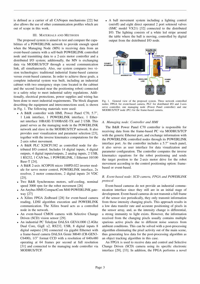
The proposed system is aimed to test and compare the capa-bilities of a POWERLINK network to provide enough speedwhen the Managing Node (MN) is receiving data from anevent-based camera with a self-built POWERLINK controllednode and trasmitting data to a 2-axis motor controller and adistributed I/O system; additionally, the MN is exchangingdata via MODBUS/TCP through a second communicationlink, all simultaneously. Also, our system compares two vi-sion technologies: traditional industrial frame-based camerasversus event-based cameras. In order to achieve these goals, acomplete industrial system was built, including an industrialcabinet with two emergency stops (one located in the cabinetand the second located near the positioning robot) connectedto a safety relay to meet industrial safety regulations. Addi-tionally, electrical protections, power supplies and wiring hasbeen done to meet industrial requirements. The block diagramdescribing the equipment and interconnections used, is shownin Fig. 1. The following materials were used:
• A B&R controller with HMI, Power Panel C70, 5.7”,1 Link interface, 1 POWERLINK interface, 1 Ether-net interface 10BASE-T/100BASE-TX and 2 USB. Thispanel serves as the managing node in the POWERLINKnetwork and slave in the MODBUS/TCP network. It alsoprovides user visualization and parameter selection [23],together with the inverse kinematics computations for the2-axis robot movement.
• A B&R PLC X20CP1382 as controlled node for dis-tributed I/O control. Includes 14 digital inputs, 4 digitaloutputs, 4 digital inputs/outputs, 2 analog inputs, 2 USB,1 RS232, 1 CAN bus, 1 POWERLINK, 1 Ethernet 10/100Base-T [24].
• A B&R 2-axis ACOPOS micro 100PD.022 inverter mod-ule for servo motor control, POWERLINK interface, 2xresolver, 2 motor connections, 2 digital inputs 24 VDC[25].
• Two B&R Synchronous motors, self-cooling, nominalspeed 3000 rpm for the robot movement [26]
• An Anybus HMS CompactCom M40 POWERLINK gate-way [27]
• A Xilinx FPGA Zedboard [28] for event-based camerareading, LDSI algorithm execution and POWERLINKcommunication. The Xilinx board acts as a controllednode in the network.
• An event-based CMOS camera with Selective ChangeDriven (SCD) vision sensor [29].
• An industrial PC Teledyne DALSA GEVA1000 (2.4GhzDual Core, GigE x2, RS232, USB, 8 digital inputs 8digital outputs) [30] connected via gigabit Ethernet witha frame-based camera DALSA Genie M640 (CR-GEN3-C6400), 1/3” format CCD with a resolution of 640x480operating at 64 frames per second at full resolution[31] and connected to the managing node controller viaMODBUS/TCP.
• A ball movement system including a lighting control(on/off) and eight direct operated 2 port solenoid valves(SMC model VX21) [32] connected to the distributedI/O. The lighting consists of a white led stripe aroundthe table where the ball is moving, controlled by digitaloutput from the dsitributed I/O node.
Fig. 1. General view of the proposed system. Three network controllednodes: FPGA for event-based camera, PLC for distributed I/O and 2-axisservo controller, one managing node (Power Panel controller) and oneMODBUS/TCP node (PC) for the frame-based camera.
A. Managing node: Controller and HMI
The B&R Power Panel C70 controller is responsible forreceiving data from the frame-based PC via MODBUS/TCPwith the generic Ethernet port, and exchange information withthe POWERLINK controlled nodes through its POWERLINKinterface port. As the controller includes a 5.7” touch panel,it also serves as user interface for data visualization andparameter configuration. The controller computes the inversekinematics equations for the robot positioning and sendsthe target position to the 2-axis motor drive for the robotmovement according to the control positioning option: frame-based or event-based.
B. Event-based node: SCD camera, FPGA and POWERLINKprotocol
Event-based cameras do not provide an industrial commu-nication interface since they still are in an initial stage ofdevelopment. Event-based cameras do not transmit a full frameof the sensor size periodically, they only transmit informationfrom those intensity changing pixels. This approach results ina low data transfer rate and accurate positioning of pixels inthe sensor array, and, as the intensity change is differential,a strong immunity to light exists. However, the informationreceived from the changing pixels usually contains multiplespurious active pixels due to different noise sources fromambient conditions. This can be solved with a post-processingalgorithm eliminating the pixel activity out of the main scene,thus generating less data for the post-processing algorithm asan object tracking algorithm in this case.
An FPGA is used to receive data and control and SelectiveChange Driven (SCD) camera using its specific electronicinterface [29], [33]. In addition, the FPGA performs a novel
Page 3
event-based LDSI data filtering and tracking algorithms pro-posed in this work (see section IV) and also includes all theobjects and data required by the POWERLINK standard sothat the FPGA can act as a controlled node by communicatingwith the Anybus CompactCom POWERLINK device whichprovides the physical POWERLINK bus connection.
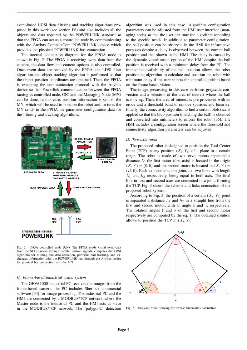
The internal connection diagram for the FPGA node isshown in Fig. 2. The FPGA is receiving event data from thecamera, the data flow and camera options is also controlled.Once event data are received by the FPGA, the LDSI filteralgorithm and object tracking algorithm is performed so thatthe object position coordinates are obtained. Then, the FPGAis executing the communication protocol with the Anybusdevice so that Powerlink communication between the FPGA(acting as controlled node, CN) and the Managing Node (MN)can be done. In this case, position information is sent to theMN, which will be used to position the robot and, in turn, theMN sends to the FPGA the parameter configuration data forthe filtering and tracking algorithms.
Fig. 2. FPGA controlled node (CN). The FPGA reads visual event-datafrom the SCD camera through parallel custom signals, computes the LDSIalgorithm for filtering and data reduction, performs ball tracking, and ex-changes information with the POWERLINK bus through the Anybus devicefor physical bus connection with the MN.
C. Frame-based industrial vision system
The GEVA1000 industrial PC receives the images from theframe-based camera, the PC includes Sherlock commercialsoftware [34] for image processing. The industrial PC and theHMI are connected by a MODBUS/TCP network where theMaster node is the industrial PC and the HMI acts as slavein the MODBUS/TCP network. The ’polygonC’ detection
algorithm was used in this case. Algorithm configurationparameters can be adjusted from the HMI user interface (man-aging node) so that the user can tune the algorithm accordingto the specific needs. In addition to parameter configuration,the ball position can be observed in the HMI for informativepurposes despite a delay is observed between the current ballposition and that shown in the HMI. The delay is caused bythe dynamic visualization option of the HMI despite the ballposition is received with a minimum delay from the PC. Theimmediate availability of the ball position allows the robotpositioning algorithm to calculate and position the robot withminimum delay if the user selects the control algorithm basedon the frame-based vision.
The image processing in this case performs greyscale con-version and a selection of the area of interest where the ballis moving. Then, the area of interest is pre-processed with anerode and a threshold band to remove spurious and binarize.Finally, the connectivity algorithm to find a certain blob size isapplied so that the blob position (matching the ball) is obtainedand converted into milimeters to inform the robot [35]. TheHMI includes a configuration screen where the threshold andconnectivity algorithm parameters can be adjusted.
D. Two-axis robot
The proposed robot is designed to position the Tool CenterPoint (TCP) in any position (Xi, Yi) of a plane in a certainrange. The robot is made of two servo motors separated adistance D, the first motor (first axis) is located in the origin(X,Y ) = (0, 0) and the second motor is located in (X,Y ) =(D, 0). Each axis contains one joint, i.e. two links with lengthL1 and L2 respectively, being equal in both axis. The finallink in first and second axes are connected in a joint, formingthe TCP. Fig. 3 shows the scheme and links connection of theproposed robot system.
According to Fig. 3, the position of a certain (Xi, Yi) pointis separated a distance h1 and h2 in a straight line from thefirst and second motor, with an angle β and γ, respectively.The rotation angles ξ and σ of the first and second motorrespectively are computed by the eq. 1. The obtained solutionallows to position the TCP in (Xi, Yi).
Fig. 3. Two-axis robot drawing for inverse kinematics calculation.
Page 4

h12 = Xi
2 + Yi2
h22 = (D −Xi)
2+ Yi
2
γ = arccos
(Xi
h1
)β = arccos
(D −Xi
h2
)ω = arccos
(h21 + L2
1 − L22
2h1L1
)θ = arccos
(h22 + L2
1 − L22
2h1L1
)σ = 180− θ − βξ = ω + θ
(1)
The robot arms were mechanically designed and createdfor this application using CAM-milled aluminium for rigidity.The bearings are installed in the joints to reduce friction andimprove accuracy.
E. Pneumatic and lighting system
The B&R PLC X20CP1382 serving as distributed I/Ocontrolled node in the POWERLINK network controls thepneumatic system for air blowing to the ball. Three differentball paths are defined acoording to three respective valvessequence, which can be switched from the HMI. The digitalouputs are connected to respective relays for valve switching.One additional output is used for led lighting of the ball table.
By means of the HMI, the user can select different optionsfor valve switching, changing speed and the sequence ofactivation so that different ball movements can be forced.
IV. LDSI AND TRACKING ALGORITHMS FOREVENT-BASED CAMERA IN FPGA
This work proposes a novel algorithm for filtering noisegenerated in event-based cameras and reducing the amountof redundant or irrelevant data. The algorithm, called LessData Same Information (LDSI) has a neuromorphic basis asdescribed in E.M. Izhikevich [3]. The goal is not to emulate afull neuromorphic system but to take advantage of some bioin-spired concepts about biological neurons in order to reducedata transmission without loss of information. The definedmodel and its comparison to a biological neuron is shownin Fig. 4. The layer-based neural model, similar to biologicalneural networks, can be observed. Units from ’Slayer’ act asthe dendrites feeding data to the nucleus (’Dlayer’) whichforward information to a wide number of synaptic terminals(’Alayer’).
The model defines a cluster of layers serially interconnected:• The first layer corresponds to an M × N sensory layer
(’Slayer’) which generates the events. In this case, wehave M × N = 128 × 128 units corresponding to thenumber of pixels in the used SCD camera. Other event-based sensors could also be used (tactile, auditory).
• The second layer called ’Dlayer’ is a (M − 2)× (N − 2)units in size. This size allows to discard the border effectsfor the next layer and control the excitation rate of eachXY unit in the layer. Each XY unit in ’Dlayer’ is con-nected to its equivalent XY unit and all ij surrounding
Fig. 4. Top: interrelation between the different layers created in the LDSIalgorithm. Lines among layer show the interconnections and data flow fromthe events generated in an event sensor (SCD camera in this case) to theoutput layer ’Player’. Bottom: Equivalence of the proposed layer model inthe algorithm with a biological neuron.
units in the next layer for a certain neighbourhood valueor ’Depth Level, DL’. Depending on the ’DL’ value, acertain XY unit will be connected to the equivalent XYunit in ’Alayer’ (’DL’=0) or the ij and surrounding unitsaccording to the ’DL’ value.
• A third layer ’Alayer’ being (M − 2)× (N − 2) units insize. In this layer, each XY unit in the matrix receives theevents generated in the XY unit and all its surroundingunits from ’Dlayer’.
• Finally, a layer called ’Player’ being (M − 2)× (N − 2)in size provides the output. Layer ’Player’ has the samestructure than the input layer; this approach allows thisprocessing system to be included in any already existingevent processing system since it could interpret the outputlayer ’Player’ as the original input layer.
All connections and layer units have multiple parametersdefining their behaviour. In addition to ’DL’ already explained,the following parameters related to the units in the layers aredefined:
• Excitation level of core (ERCO): Magnitude of thepotential that a unit in the XY address of ’Dlayer’increases when an event is received from the unit locatedin the same XY address in ’Slayer’.
• Excitation level of connection (ERCN): The potentialincrement in the XY unit of ’Alayer’ due to an event inthe same XY address of ’Dlayer’.
• Excitation level of neighbouring connections (ERNC):When an event is produced in an XY address of ’Dlayer’this parameter corresponds to the potential increment inXY unit and its neighbouring units in ’Alayer’. Thenumber of affected units varies according to the ’DL’value.
• Threshold level of core excitation (TCE): Definesthe minimum value of excitation required for an eventgeneration in a unit in ’Dlayer’.
• Threshold level of connection excitation (TNE): De-
Page 5

fines the minimum value of excitation required for anevent generation in a unit in ’Alayer’.
• Maximum time to remember (MTR): Defines themaximum time between two events that the value ofexcitation in layers ’Dlayer’ and ’Alayer’ can remainbefore being degraded. This parameter can be associatedto a forgetting factor in the unit.
• Decrement of excitation rate potential (DERP): Thevalue to be decremented from the potential in ’Dlayer’once ’MTR’ time has passed.
• Decrement of excitation rate connection (DERC): Thevalue to be decremented from the potential in ’Alayer’once ’MTR’ time has passed.
In addition, the behaviour can be controlled by some inher-ent parameters to the events as:
• Actualtimestamp (AT): The timestamp of the actualevent present in a certain connection.
• Lasttimestamp (LT): The timestamp of the previousevent received in a certain connection.
• Deltatime (DT): Difference in milliseconds between theactual and the previous event coming from a certainconnection. If this value is higher than ’MTR’, thepotential in the units is decreased.
Each unit, identified by a unique address corresponding toits XYl position in the layer l, computes its internal potentialaccording to the event received from its direct counterpart inthe previous layer, i.e. output value from the XYl−1 unit,and the events from the surrounding units to XYl−1. Uponan event, the potential in the unit is increased by an excitationvalue which is different depending on the layer: an XYunit in ’Dlayer’ increases potential according to the eventsgenerated in the XY unit in ’Slayer’. The potential in theunit is obtained by adding all excitation values and, whenreaching a threshold, the unit generates an output event. Fig.5 shows an example for the behaviour of the LDSI algorithm.In this figure, input events from the sensory layer ’Slayer’in a certain XY unit in ’Dlayer’ are received, increasing itspotential by the amount value defined by ’ERCO’. If no newevents appear during an inter-event time (’DT’ higher than’MTR’), the potential is decreased by ’DERP’. When thepotential at the unit reaches its threshold ’TCE’, an outputevent is generated and transmitted to ’Alayer’ which creates apotential increase by ’ERCN’ at the XY unit in this layer anda potential increase by ’ERNC’ in its neighbours (the numberof affected neighbours is given by ’DL’). When the potentialvalue at a certain unit in ’Alayer’ reaches the threshold valuedefined by ’TNE’, an output event in the corresponding unitof ’Alayer’ is generated.
The model defined in this algorithm makes that those eventsmore distant in time and space to others have increased possi-bility of being discarded and considered as noise unless a newstimulation is received inside a certain elapsed time; dependingon the connections of the neurons and their excitation levels(strengthness), an output event is generated.
After processing all layers, an event in a certain XY unitof ’Player’ is generated as long as the previous connectionsand core excitation levels have been strong enough to achieve
Fig. 5. Event processing example for the XY unit in ’Dlayer’, a XY unit in’Alayer’, and a neighbour unit to XY upon the reception of input events. Thepotential value in each unit increases with input events and, when above athreshold, an output event is generated; if no events enter the unit after a timedefined by ’MTR’, the potential is decreased. Depending on the layer unitreceiving an event from the same XY unit in the previous layer, or eventsbeing received from neighbour units, the potential increment value is definedby ’ERCN’ or ’ERNC’, respectively.
a potential value above the threshold.Experimentally, we have determined that the range of
the parameters ’ERCO’, ’ERCN’, ’ERNC’, ’TCE’, ’TNE’,’DERP’ and ’DERC’ should be kept between 0 and 10;otherwise, a high computational cost is required without extrabenefits. The ’MTR’ parameter has time units, it must beadjusted depending on the event activity (in this case, relatedto scene activity). Values in the order of 500 milliseconds aretypical since using lower values increases the filter restrictive-ness of the algorithm. Fig 6 shows the results of the filterfor low, medium and high filtering levels by using differentparameter values.
A. Tracking algorithm for the event-based camera
After processing the event data from the SCD camera usingthe LDSI filtering algorithm, the relevant events correspondingto the object are obtained. As event data are continous in
Page 6

Fig. 6. Low (a), medium (b) and high (c) LDSI filtering. Filter parametersallow the adjustement of output results.
time, 20 consecutive events are received. These event data arecomputed to obtain the position for each of them and then, avicinity algorithm is applied so that the position of the eventwith most neighbouring events is the winner being the latestthe most valid in case of several positions having the samevicinity value.
So that this tracking provides a good performance, the LDSIfilter must be fine-tuned to avoid noise influence generatingfalse event positions.
V. RESULTS
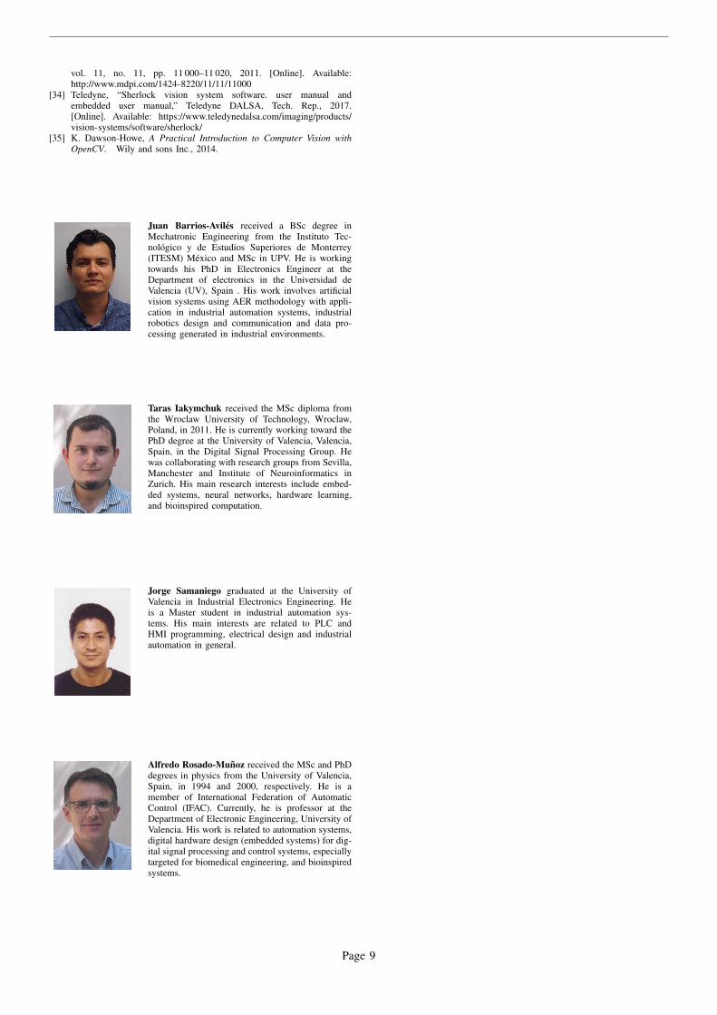
After the final commissioning of the system, configurationof the motor drive to accomodate the dynamics of the robot,and programming of all devices as seen in Fig. 7, the testingshowed that motor speed was satisfactory for fast positioning,showing stability and low vibration.
The tracking algorithm was tested for the event-basedcamera. The test consisted on high, medium and low speed ballspeed movement across the whole area and also in a reducedarea to verify the accuracy. In all cases, the controller is ableto receive the position from the FPGA node and send to themotor drive with enough speed to provide good positioning.Since no position prediction algorithm is included, there exista delay in the actual ball position and the Tool Center Pointof the robot, which is negligible in most of the cases.
In case of the frame-based camera, similar results areobtained. Thus, both technologies are able to provide goodpositioning, also showing that bus communications are ableto provide enough speed to provide fast motor response toconstant positioning changes. The main difference betweenevet-based and frame-based techniques lies in the fact thatframe-based cameras require a high computational cost: adedicated industrial PC with isolated Ethernet communicationbetween PC and frame-based camera is required, image pro-cessing algorithms are computationally demanding, and powerconsumption is high. However, the same result is achieved bya simpler system based on a low cost FPGA with very lowpower consumption.
VI. CONCLUSION
The integration of new devices in industry is a need inmany factories where custom processes need to be carriedout, and many modern tasks are requiring high-throughputcommunication interfaces. This work describes the sucessfulintegration of an event-based camera into the IEEE standardPowerlink communication bus by means of an FPGA. The
camera is seen as a controlled node in the network where acommercial B&R controller acts as managing node. In addi-tion, the FPGA performs local computing for data filtering andobject tracking, sending the tracking position to the controllednode which in turn, controls a 2-axis robot custom designedwhere the inverse kinematics computation for positioning isdone by the managing node. Alternatively, the 2-axis robotcan be controlled by a traditional frame-based camera so thata comparison between both image acquisition and trackingprocessing can be done. In this case, both cameras are ableto provide enough speed for positioning. However, the framebased camera requires the use of a dedicated computer withisolated high bandwidth communication between the PC andthe camera, resulting in a high power consumption and a morecomplex system while the same goal can be achieved by acustom made electronics.
ACKNOWLEDGMENTS
The authors would like to thank Prof. Fernando Pardo forhis help and support in communitcating with the SCD cameradeveloped by his research group at University of Valencia,and Prof. Vicente Martinez for his support in the mechanicaldesign and manufacturing of the robot links. We would alsolike to thank Mr. Alejandro Cortina for his collaboration inthe setting up for all the electrical system and cabinet design.
REFERENCES
[1] J. D. Decotignie, “Ethernet-based real-time and industrial communica-tions,” Proceedings of the IEEE, vol. 93, no. 6, pp. 1102–1117, June2005.
[2] R. Berner, C. Brandli, M. Yang, S.-C. Liu, and T. Delbruck, A 240x18010mW 12us latency sparse-output vision sensor for mobile applications.IEEE, Jun 2013, pp. C186–187.
[3] E. M. Izhikevich, “Simple model of spiking neurons,” IEEE Transactionson Neural Networks, vol. 14, no. 6, pp. 1569–1572, Nov 2003.
[4] S. B. Furber, D. R. Lester, L. A. Plana, J. D. Garside, E. Painkras,S. Temple, and A. D. Brown, “Overview of the spinnaker systemarchitecture,” IEEE Transactions on Computers, vol. 62, no. 12, pp.2454–2467, Dec 2013.
[5] A. Rios-Navarro, E. Cerezuela-Escudero, M. Dominguez-Morales,A. Jimenez-Fernandez, G. Jimenez-Moreno, and A. Linares-Barranco,“Real-time motor rotation frequency detection with event-based visualand spike-based auditory aer sensory integration for fpga,” in 2015International Conference on Event-based Control, Communication, andSignal Processing (EBCCSP), June 2015, pp. 1–6.
[6] R. Serrano-Gotarredona, T. Serrano-Gotarredona, A. J. Acosta-Jimenez,and B. Linares-Barranco, “An arbitrary kernel convolution aer-transceiver chip for real-time image filtering,” in 2006 IEEE Interna-tional Symposium on Circuits and Systems, May 2006, pp. 4 pp.–.
[7] M. Rivas-Perez, A. Linares-Barranco, A. Jimenez-Fernandez, A. Civit,and G. Jimenez, “Aer spike-processing filter simulator: Implementationof an aer simulator based on cellular automata,” in Proceedings ofthe International Conference on Signal Processing and MultimediaApplications, July 2011, pp. 1–6.
[8] A. Espnola, A. Romay, T. Baidyk, and E. Kussul, “Robust visionsystem to illumination changes in a color-dependent task,” in 2011 IEEEInternational Conference on Robotics and Biomimetics, Dec 2011, pp.521–526.
[9] W. K. Lin, C. M. Uang, P. C. Wang, and Z. S. Ho, “Led strobe lightingfor machine vision inspection,” in 2013 International Symposium onNext-Generation Electronics, Feb 2013, pp. 345–346.
[10] H. Kim, K. Cho, S. Kim, and J. Kim, “Color mixing and random searchfor optimal illumination in machine vision,” in Proceedings of the 2013IEEE/SICE International Symposium on System Integration, Dec 2013,pp. 907–912.
Page 7
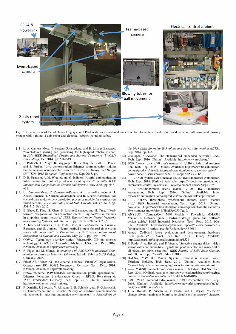
Fig. 7. General view of the whole tracking system. FPGA node for event-based camera on top, frame based and event based cameras, ball movement blowingsystem with lighting, 2-axis robot and electrical cabinet including safety.
[11] L. A. Camuas-Mesa, T. Serrano-Gotarredona, and B. Linares-Barranco,“Event-driven sensing and processing for high-speed robotic vision,”in 2014 IEEE Biomedical Circuits and Systems Conference (BioCAS)Proceedings, Oct 2014, pp. 516–519.
[12] J. Partzsch, C. Mayr, B. Vogginger, R. Schffny, A. Rast, L. Plana,and S. Furber, “Live demonstration: Ethernet communication linkingtwo large-scale neuromorphic systems,” in Circuit Theory and Design(ECCTD), 2013 European Conference on, Sept 2013, pp. 1–1.
[13] D. B. Fasnacht, A. M. Whatley, and G. Indiveri, “A serial communicationinfrastructure for multi-chip address event systems,” in 2008 IEEEInternational Symposium on Circuits and Systems, May 2008, pp. 648–651.
[14] L. Camunas-Mesa, C. Zamarreno-Ramos, A. Linares-Barranco, A. J.Acosta-Jimenez, T. Serrano-Gotarredona, and B. Linares-Barranco, “Anevent-driven multi-kernel convolution processor module for event-drivenvision sensors,” IEEE Journal of Solid-State Circuits, vol. 47, no. 2, pp.504–517, Feb 2012.
[15] B. Zhao, R. Ding, S. Chen, B. Linares-Barranco, and H. Tang, “Feed-forward categorization on aer motion events using cortex-like featuresin a spiking neural network,” IEEE Transactions on Neural Networksand Learning Systems, vol. 26, no. 9, pp. 1963–1978, Sept 2015.
[16] A. Jimenez-Fernandez, J. L. F. del Bosh, R. Paz-Vicente, A. Linares-Barranco, and G. Jimnez, “Neuro-inspired system for real-time visionsensor tilt correction,” in Proceedings of 2010 IEEE InternationalSymposium on Circuits and Systems, May 2010, pp. 1394–1397.
[17] ODVA, “Technology overview series: Ethernet/IP, CIP on ethernettechnology,” ODVA Inc, Ann Arbor, Michigan, USA, Tech. Rep., 2016.[Online]. Available: https://www.odva.org/
[18] R. Pigan and M. Metter, Automating with PROFINET: Industrial Com-munication Based on Industrial Ethernet, 2nd ed. Publicis MCD Verlag,Germany, 2008.
[19] EtherCAT, “EtherCAT the ethernet fieldbus,” EtherCAT organisation,Ostendstrasse 196, 90482 Nuremberg, Germany, Tech. Rep., 2014.[Online]. Available: https://ethercat.org
[20] EPSG, “Ethernet POWERLINK communication profile specification,”Ethernet Powerlink Standarisation Group - EPSG, Bonsaiweg 6,15370 Fredersdorf, Germany, Tech. Rep., 2013. [Online]. Available:http://www.ethernet-powerlink.org/
[21] P. Danielis, J. Skodzik, V. Altmann, E. B. Schweissguth, F. Golatowski,D. Timmermann, and J. Schacht, “Survey on real-time communicationvia ethernet in industrial automation environments,” in Proceedings of
the 2014 IEEE Emerging Technology and Factory Automation (ETFA),Sept 2014, pp. 1–8.
[22] CANopen, “CANopen The standardized embedded network,” CAN,Tech. Rep., 2016. [Online]. Available: http://www.can-cia.org/
[23] B&R, “Power panel C70 user’s manual v1.1,” B&R Industrial Automa-tion, Tech. Rep., 2015. [Online]. Available: https://www.br-automation.com/en/products/visualization-and-operation/power-panel-t-c-series/power-panel-c-series/power-panel-c70/4ppc700573-20b/
[24] ——, “X20 system user’s manual v3.35,” B&R Industrial Automation,Tech. Rep., 2016. [Online]. Available: https://www.br-automation.com/en/products/control-systems/x20-system/compact-cpus/x20cp1382/
[25] ——, “ACOPOSmicro user’s manual v1.20,” B&R IndustrialAutomation, Tech. Rep., 2016. [Online]. Available: https://www.br-automation.com/en/products/motion-control/acoposmicro/
[26] ——, “8LVA three-phase synchronous motors. user’s manualv1.0,” B&R Industrial Automation, Tech. Rep., 2017. [Online].Available: https://www.br-automation.com/en/products/motion-control/8lva-compact-motor/size-1/8lva13ee030ffgg-0/
[27] ANYBUS, “CompactCom M40 Module - Powerlink. MMA316Version 2. Network guide, Hardware design guide and Softwaredesign guide,” HMS Industrial Networks, Tech. Rep., 2017. [On-line]. Available: https://www.anybus.com/support/file-doc-downloads\/compactcom-40-series-specific/?ordercode=AB6611
[28] Avnet, “Zedboard (zynq evaluation and development). hardwareusers guide v2.2,” Avnet, Tech. Rep., 2014. [Online]. Available:http://zedboard.org/support/documentation/1521
[29] F. Pardo, J. A. Boluda, and F. Vegara, “Selective change driven visionsensor with continuous-time logarithmic photoreceptor and winner-take-all circuit for pixel selection,” IEEE Journal of Solid-State Circuits,vol. 50, no. 3, pp. 786–798, March 2015.
[30] DALSA, “GV1000 Vision System. Installation manual v4.5,”Teledyne DALSA, Tech. Rep., 2016. [Online]. Available: https://www.teledynedalsa.com/imaging/products/vision-systems/systems/
[31] ——, “GENIE monochrome series manual,” Teledyne DALSA, Tech.Rep., 2011. [Online]. Available: http://www.teledynedalsa.com/imaging/products/cameras/area-scan/genie/CR-GEN3-M640X/
[32] SMC, “VX21 solenoid valve manual,” SMC Corporation, Tech. Rep.,2016. [Online]. Available: http://www.smcworld.com/products/en/get.do?type=GUIDE&id=VX2-E
[33] J. A. Boluda, P. Zuccarello, F. Pardo, and F. Vegara, “Selectivechange driven imaging: A biomimetic visual sensing strategy,” Sensors,
Page 8
vol. 11, no. 11, pp. 11 000–11 020, 2011. [Online]. Available:http://www.mdpi.com/1424-8220/11/11/11000
[34] Teledyne, “Sherlock vision system software. user manual andembedded user manual,” Teledyne DALSA, Tech. Rep., 2017.[Online]. Available: https://www.teledynedalsa.com/imaging/products/vision-systems/software/sherlock/
[35] K. Dawson-Howe, A Practical Introduction to Computer Vision withOpenCV. Wily and sons Inc., 2014.
Juan Barrios-Aviles received a BSc degree inMechatronic Engineering from the Instituto Tec-nologico y de Estudios Superiores de Monterrey(ITESM) Mexico and MSc in UPV. He is workingtowards his PhD in Electronics Engineer at theDepartment of electronics in the Universidad deValencia (UV), Spain . His work involves artificialvision systems using AER methodology with appli-cation in industrial automation systems, industrialrobotics design and communication and data pro-cessing generated in industrial environments.
Taras Iakymchuk received the MSc diploma fromthe Wroclaw University of Technology, Wroclaw,Poland, in 2011. He is currently working toward thePhD degree at the University of Valencia, Valencia,Spain, in the Digital Signal Processing Group. Hewas collaborating with research groups from Sevilla,Manchester and Institute of Neuroinformatics inZurich. His main research interests include embed-ded systems, neural networks, hardware learning,and bioinspired computation.
Jorge Samaniego graduated at the University ofValencia in Industrial Electronics Engineering. Heis a Master student in industrial automation sys-tems. His main interests are related to PLC andHMI programming, electrical design and industrialautomation in general.
Alfredo Rosado-Munoz received the MSc and PhDdegrees in physics from the University of Valencia,Spain, in 1994 and 2000, respectively. He is amember of International Federation of AutomaticControl (IFAC). Currently, he is professor at theDepartment of Electronic Engineering, University ofValencia. His work is related to automation systems,digital hardware design (embedded systems) for dig-ital signal processing and control systems, especiallytargeted for biomedical engineering, and bioinspiredsystems.
Page 9