an entity system as the base of a node graph visual ... entity system as the base of a node graph...
TRANSCRIPT

An Entity System as the base of a Node Graph Visual Programming Language
Student: Sven von Brand
Professor: Dr. Hernán Astudillo
Mentor: Benoit Bolsee
Abstract
Entity systems have become a popular approach to game development due to their advantages in reusing code, adding new logic to entities by relating components to it without rewriting the entities behavior, and minimizing code replication. The Blender game engine (an open source 3D-modeling suite) offers a graphical editor interface that's close to a node-based representation of game context behavior. However, extending and customizing games has become very hard for more complex games, due to very specific logic for each game object that's very hard to reuse and that complex visual logic is hard to read, being most games a combination of hard coded Python an visual logic.This article describes a visual programming node editor for the Blender Game Engine, by providing an Entity System and building the node editor around a special-purpose component-oriented programming language. This proposal is part of an effort to make the visual logic more adequate for game development, adding the possibility to reuse logic, easier to read logic, more flexibility to design logic, while keeping current capabilities.This proposal has been validated with a prototypical implementation of an Entity System through Python on top of the current Blender Game Engine.The new logic editor for the Blender Game Engine will allow non-programmers to build simpler and more self-explanatory visual descriptions of game logic and the ability to share and reuse logic easier in teams and between projects. The engine will be released under a BSD license to allow other projects or companies to use the node engine.
IntroductionAn Entity System is a system that's based on the proposition that there are entities which can add, remove and use different components to define it's behavior and properties. The entity itself doesn't contain any information, methods or properties, it's just a label that lets the combination of many components come to life.
As such it is recommended to keep the entities as a very clean element in the system, this allows to easily change the behavior of entities with ease and there's less code replication as there's the clear
ability to reuse components easily and even in runtime.
The components of the system must be self contained to allow them to work with many different entities and keep the flexibility of the system as high as possible.
There are some discussions about how an Entity System should be made or exactly what does it mean, but for the work currently done the definition that best describe the work is that of Adam Martin in his website [2].
As for the node editor, the definition of it as a programming language allows to solve many problems by using the body of knowledge of programming language engineering. In this aspect, the current work follows very closely Anneke Kleppe's work in her book “Software Language Engineering, Creating Domain-Specific Languages Using Metamodels” [1]. It might sound strange to some to treat a visual representation as a programming language and one might think the node editor is translated to some form of code that is the actual programming language, but the powerful idea behind this project is to actually treat the node graphs and visual representation as the language itself.
Blender has a working visual interface to make interactive content, this part of Blender is called the Blender Game Engine. The engine has support for physics, an excellent OpenGL features, access to a working animation system, a python API and a graphical logic editor to create the interactive content. The current logic editor can be combined with python to make advanced interactive content, but the visual logic made with the engine is hard to re-use and hard to read.
The current graphical logic editor is based in three columns of elements. The first column are sensor elements, the second column are controllers elements and the third column are actuators elements. The description of each element is as follows:
Sensors: This elements check for a certain action to be met, in which case they through either a true if the condition is met or a false if a action is not met. Examples are keyboard events, property comparisons and collision detection.
Controllers: This elements are logic statements which will send a signal to any connected actuator if they are met. This can be a preset of logic statements or a defined expression. It is also possible to run a python script instead of using a logic statement. This script can access all connected Sensors and Actuators and can also do some actions directly through the Blender Game Engine python API. The Controllers can be associated with a state, this functionality allows to be able to encapsulate some logic and to make conditional and triggered behaviors in objects. States are exclusive to controllers.
Actuators: This elements are triggered when they receive a signal from a controller, this are visible actions in the content like motion, editing the object mesh and changing properties values.

Currently the system checks sensors and controllers in each object to make each logic step, if an object is duplicated this mean that all the needed data for the object must be duplicated also.
Problem to solveCurrently Blender has a three columns graphic logic editor that's closer to an object oriented approach, if each element in the columns is treated as an object, than to a component oriented approach. The Game Objects function as a reference attached to each element in the columns and what in an entity system would be a component is currently the combination of elements related in the current system. This makes it very hard to actually reuse large portions of logic and very hard to actually read the behavior of it. As more functionality is added to a game object, the current functionality makes the visual logic representation to grow down, without the possibility of encapsulating logic beyond the use of states. States allow to encapsulate logic, but not in a way of being able to re-use it correctly.
So the main problems that need to be solved are:
Visual logic must be easier to comprehend, follow and modify
Behaviors must be reusable and easy to combine
Engine must keep current capabilities with the new system
The proposed solution is to make a visual component oriented programming language, which in itself has many problems to be solved. Making a programming language requires to make the formal definition of it and make enough examples to make it clear how the language works. The proposed language must be focused in a broad audience, because of this, the ease of use and easy to learn are the most important features the language must have. Although the domain of the language is specific to the Blender Game Engine, the domain must be defined as a domain generic enough to be reused in other systems, that contains game objects equivalent to those present in the Blender Game Engine.
The functionality that makes the Blender Game Engine attractive and must be kept are:
Mixing sensor, controller and actuator elements related to different game objects to make a compound.
Runtime game object duplication also duplicates relations between game objects. This is currently done by duplicating sensor, controller and actuator elements and their relation with other game object's elements, the implementation might be changed in the new system, but the functionality must be kept.
Illustration 1: Current Blender Game Engine Graphical Logic Editor
Easy access to Blender's functionality, such as animations, materials, mesh objects, boned animations and lighting.
Previous WorkBenoit Bolsee and members of the Blender community have made an extensive design document [3] of a node engine that would make the graphical logic editor easier to extend, give users more options to make understandable logic and an easier way to re-use logic encapsulating it in graphs.
The proposed improvements of this design are: easy to use, reusable, hierarchical, complete and extensible. Of the improvements, the only one which cannot be met with a language design approach is the complete improvement. It is stated in the book “Component Oriented Programming” [4] that component oriented programming is a new paradigm such as object oriented programming or functional programming, this would make the described option to use any programming style approach including object oriented and imperative programming not feasible and also not desired.
Proposed SolutionThe proposed node graph visual programming language is a very simple one which has only the following base elements:
Entity: The representation of a group of functioning and defined components, it can be related to one or many components, it doesn't have any data, only a relation with labels and local values for components related to it.
Label: Allows to relate one or more entities to one or more components.
Component: Has self contained logic as graphs and data as properties, it can be related to entities through labels.
Graph: represents logic as the combination of nodes and links.
State: A label in a component that activates or deactivates graphs.
Node: Receives and sends information through links, which are connected to Data-in and Data-out pins. Has internal logic to handle information.
Push-in and Push-out pins: Pins are related to links, each Pin can be connected to multiple links, but only be part of one Node. A link can be related
Pull-in and Pull-out pins: Pins are related to links, each Pin can be connected to multiple links, but only be part of one Node.
Push Links: A Push Link is related to a Push-out pin and a Push-in pin. Push Links have internal logic to delay transporting data and filtering, it transports entity lists from one node to another to activate them.
Pull Links: A Pull Link is related to a Pull-in pin and a Pull-out pin. The link works on demand and doesn't have logic attached to it.
Properties: Properties are specific to Components, a property can only be related to one component and accessed through a node in the graph. Properties can be private to the component, public to all components or available only to components related directly to the same entity. Also properties can be at component level or at entity level, being the later the

default use of properties. At component level, a property will only have two scopes, private to the component and global.
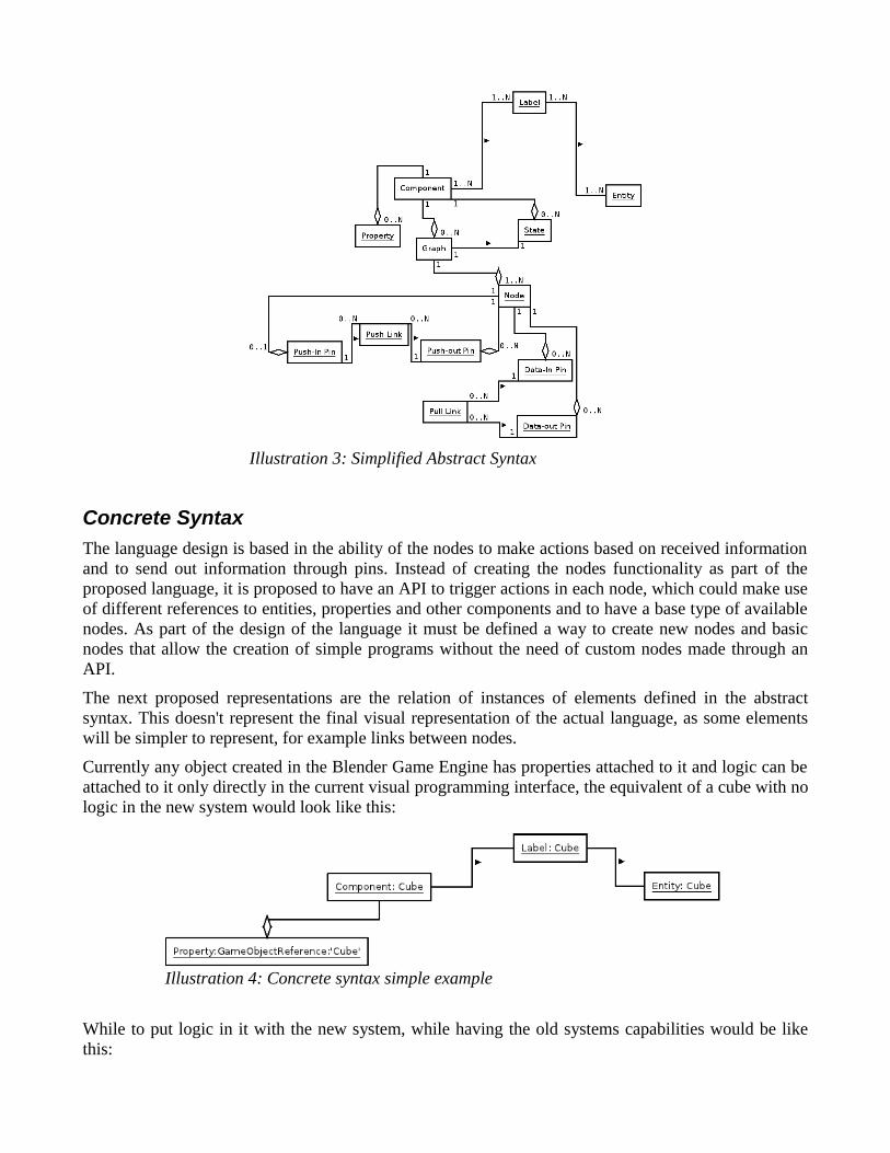
To describe the language it will be used an abstract syntax and a concrete syntax with examples.
Abstract Syntax
This syntax denotes the relation between the components but doesn't give information about how they should be combined to make a working program. This syntax is enough as a base of rules to follow and to make a simple syntax checker and to have an idea of how a program should be made using this language. To simplify the description, the used syntax will be the one in illustration 3, while the complete one is in illustration 2
Illustration 2: Abstract Syntax
Concrete Syntax
The language design is based in the ability of the nodes to make actions based on received information and to send out information through pins. Instead of creating the nodes functionality as part of the proposed language, it is proposed to have an API to trigger actions in each node, which could make use of different references to entities, properties and other components and to have a base type of available nodes. As part of the design of the language it must be defined a way to create new nodes and basic nodes that allow the creation of simple programs without the need of custom nodes made through an API.
The next proposed representations are the relation of instances of elements defined in the abstract syntax. This doesn't represent the final visual representation of the actual language, as some elements will be simpler to represent, for example links between nodes.
Currently any object created in the Blender Game Engine has properties attached to it and logic can be attached to it only directly in the current visual programming interface, the equivalent of a cube with no logic in the new system would look like this:
While to put logic in it with the new system, while having the old systems capabilities would be like this:
Illustration 4: Concrete syntax simple example
Illustration 3: Simplified Abstract Syntax

The advantage of the component approach is to be able to leave the properties in one component and the graph doing the motion in another component, this way it could be attached to many entities very easily.
It is also proposed that labels can be dynamically linked to components and entities, making the system even more flexible.
Components representation
For the concrete syntax the representation in illustrations 4, 5 and 6, the syntax used serves to easily see the abstract syntax applied, but using this as the final concrete syntax would be impractical, so a set of visual components and it's relations is presented for this document. This representation is also not a final representation, as the final representation must be integrated in the blender interface, but is closer
Illustration 6: Concrete syntax simple example 3
Illustration 5: Concrete syntax simple example 2

to a representation a user should expect of the proposed language. Colors are used to better identify the different elements, but
Entity: An entity will be a rectangle with the option to attach labels to it. As a component is attached to an entity, it will be possible to set an initial state to this component related to this entity and starting values to properties accessing a special menu from a label. The only way to attach a component is through labels. Components cannot be edited through the entity menu, only the initial values and activated states can be changed.
Component: a component will be the combination of a rectangle with the name of the component, a list of labels, a list of properties and a list of states related to it. It will be linked to the graphs it owns. The values in the properties and active states are the default initial values when a component is related to an entity. The letter to the left of properties is the scope of the property. For Entity properties “P” means the property is public to any component, “S” means that the access is shared only to other components directly related to that entity and “L” means that the property is at entity level but it is local and accessible only to the component that has the property. For Component properties “L” means the property is local and can be accessed only through that component, “G” means that the property is global and unique to all components.
Graphs: A graph is the combination of nodes related through links, it will have a rectangle with an identifier of the graph and a combo-box of states that can be associated to the graph, only one graph can be associated to each state. If the component is related to an active state, the graph will be active, otherwise the graph is not active. States of graphs cannot be custom to an entity, but the initial active states of a component can be custom to an entity.

Node: A node will be a square with an identifier, which will have pins attached to it in each side and will have possible input data or optional elements inside of it. In some cases new pins can be added. Top pins (red) are Pull-in pins, bottom pins (brown) are Pull-out pins, The left pin (yellow) is the Push-in pin (there can only be one of this) and right pins are Push-out pins. The “Node Type” is a combo box with available nodes. The “Custom Node Data” field will be different for each node.
Pins: The Push-in pin will be in the left side of a node and Push-out pins will be in the right side of a node. Pull-in pins will be in the top side of a node and Pull-out pins will be in the bottom side of a node. All pins will be simple small named circles.
Labels: Labels will be added to an entity or component through a list.
Special nodes
It is proposed to have some basic nodes defined as part of the language to have a set of functionality available without the need of having custom nodes. All nodes have a Push-out pin, which can be left unconnected, this allows to have many nodes be called sequentially, this Push-out pin automatically emits a pulse to connected nodes once the nodes finishes execution.
The proposed nodes are:
If node: This node will have one or more Pull-in pins, will have space to put a logic statement very much like an if statement and a Push-in pin. This node will have two special Push-out pins apart from the default one, a true Push-out pin and a false Push-out pin.
Switch node: This node will have only one Push-in pin and at least one Push-out pin. This node will compare the data received in the Push-in pin with a value for each Push-out pin. If the value of the received data is the same as the value assigned to a Push-out pin, a pulse through that pin will be send. There will be a switch default Push-out pin (apart from the default Push-out pin), which will activate if no Push-out pin value is met.

Property value node: This node will have one Pull-out pin, it will send the value of a defined property. It can optionally have a Pull-in pin to get an Entity reference. The Entity reference can be set to default.
Property editor node: This node has one Push-in pin, and can optionally have one or more Pull-in pin. It will be able to change the value of a property in different ways, for example, using a value from a Pull-in pin or a defined value. In case of numbers it will allow setting a value and adding a value, both from the received data or predefined. In case of strings it will allow to set data only. In case of a boolean it will allow to set a value or toggle the value.
Entity node: This node will have only one Pull-out pin, which upon request will send a reference of a defined entity in the node through the pin.
Label node: Allows to add a label to a component or entity it has a Push-in pin to activate and can have a Pull-in pin, from which to get the label to add.
Reference node: This node will have a Pull-in pin that can receive a reference to an entity and at least one Pull-out pin. A Pull-out pin will send upon request the value of a property attached to that entity through components. A property to use can be defined for each Pull-out pin. Properties include references to game objects that Entity may have.
State node: This node sets the activated nodes, activates a state or deactivates a state. It has one Push-in pin and a Pull-in pin, if a pulse comes from the pin it can set a defined state for the entity's component or get a state's name from it's pull-in pin.
Always node: This node has only a Push-out pin, which always sends a pulse. It can be set to send a pulse each step or only once when it becomes active.
Delay node: This node has only a Push-out pin, which sends a pulse after a defined delay inside the node and a Pull-out pin that allows to check if the sensor is active. It can also be defined if it should send a pulse only once or to start the delay again once it sends the pulse.
It is also proposed to have equivalent nodes to sensor elements in the current blender system, such as:
Keyboard Node: Based on the Keyboard Sensor. It has a Push-out pin, sending a pulse when a key, selected inside the node, is pressed and a Pull-out pin that allows to check if the sensor is active.
Mouse Node: Based on the Mouse Sensor. It has a Push-out pin, sending a pulse when a defined mouse click is pressed or another mouse related condition is true and a Pull-out pin that allows to check if the sensor is active. The options will be available inside the node in a similar way of the current Mouse Sensor element.
Collision Node: Based on the Collision Sensor. It has a Push-out pin, sending a pulse when a defined collision occurs and a Pull-out pin that allows to check if the sensor is active. The options will be available inside the node in a similar way of the current Collision Sensor element. It is proposed for it to optionally have a Pull-out pin, which can get the colliding game-object reference.
Many nodes must be made to replicate actuator elements, but for this document the following will be defined:

Motion Node: Based on the Motion Actuator. It has a Push-in pin, which activates the node, and a Pull-in pin, which fetches a reference to a game object. The game-object reference can be set inside the node manually. It is proposed to have an optional Pull-in pin to have motion be affected by calculated data or data defined in a node.
Portal Node: A graph can have none or more Portal Nodes. this node has a Push-in pin and has a Push-out pin it can also have a Pull-in pin to store data. This node can reference a Portal In Node by name to activate it or share data.
Portal In Node: A graph can have none or more Portal In Nodes, which act as sensors. It has a Push-out pin and a Pull-out pin, the Push-out pin is activated if the a Portal Node references this node, and data can be pulled out of the node if it was stored in the Portal Node. All actions are local to entities.
How to make custom nodes
It is proposed to have access to the API and be able to create python modules inside a node that run when it receives Push-in pin's data and uses Pull-in pin's data and Push-in pin's data. The node can send messages through the Push-out pin's or send a message through a Pull-out pin on demand. This approach needs coding and hiding logic in code from the nodes but it is similar to how the current Blender Game Engine handles python scripts.
It is also proposed to have a custom node generator from a special graph. This nodes could be saved in a library to be used and shared. The component approach should make it easier to make generic custom nodes. It is proposed to have four initial nodes in the graph, each with only one type of pin: a Push-in Node, a Push-out Node, a Pull-in Node and a Pull-out Node. The initial nodes would be the interface of the node generated with the graph. Each of this initial nodes can be filled with pins to make the logic, but the pins of the generated node will only be: the Push-in pin from the Push-in Node, all Push-out pins from the Push-out Node, all the Pull-in pins from the Pull-in Node and all the Pull-out pins from the Pull-out Node.
Examples without custom nodes
The following examples show the strengths of the systems with only the base proposed language using the proposed design.
The example in illustration 7 is the same as illustration 5, which shows how the logic is encapsulated in the component and not in the entity. It is also used a component to refer to the game object, making the logic easy to use with other game objects and entities.

In the illustration 8 the simple example described in the illustration 6 is showed with the new proposed syntax. In this example the “CubeEntity” and the “SphereEntity” have two components each. The “MovingObject” label relates each entity with the “MovingComponent”, which moves a game object referred as “GameObject”. The “GameObject” property is different in each entity as one has the “GameObject” property from the “CubeComponent” and the other has the property from the “SphereComponent”.
Illustration 7: Simple Example 2 with proposed syntax

The functionality of the previous example can also be achieved through initial values of properties in the entity. For this the “CubeComponent” and “SphereComponent” will be combined into a “GameObjectComponent” with an empty reference to a game object.
The initial default value of the “GameObject” property, which is a reference to a game object (GOR for Game Object Reference) is empty, so it is set in each entity as 'Cube' and 'Sphere' respectively. Illustration 9 shows how the initial values could be set.
Illustration 8: Simple example 3 with the proposed syntax
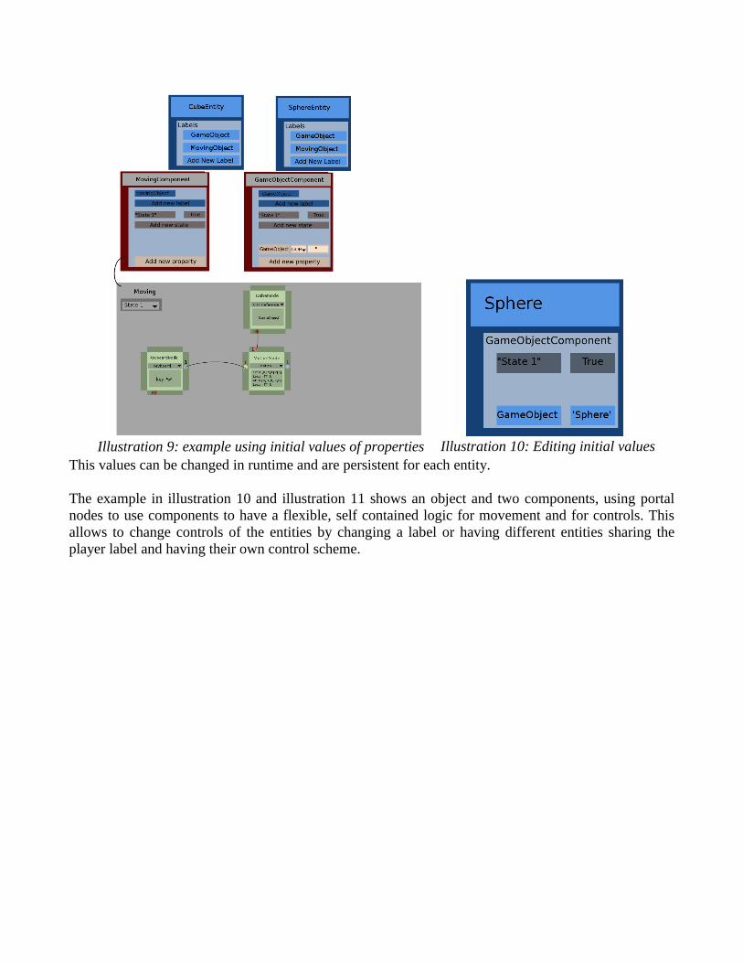
This values can be changed in runtime and are persistent for each entity.
The example in illustration 10 and illustration 11 shows an object and two components, using portal nodes to use components to have a flexible, self contained logic for movement and for controls. This allows to change controls of the entities by changing a label or having different entities sharing the player label and having their own control scheme.
Illustration 10: Editing initial valuesIllustration 9: example using initial values of properties
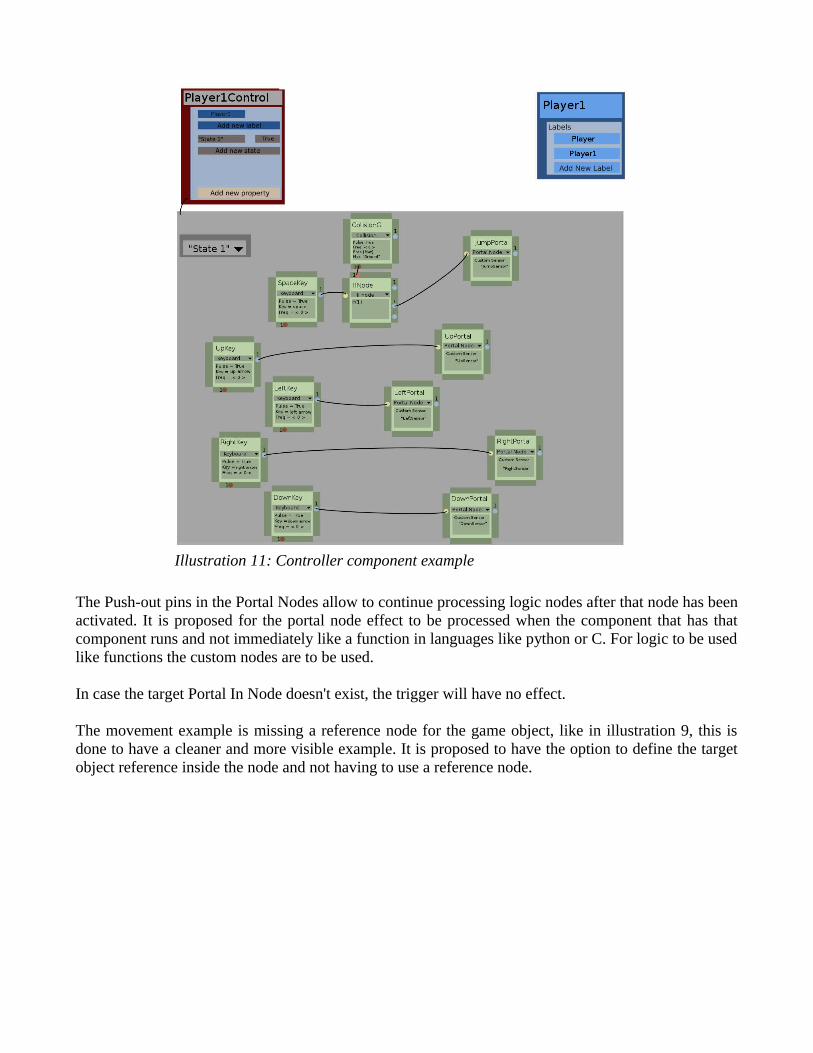
The Push-out pins in the Portal Nodes allow to continue processing logic nodes after that node has been activated. It is proposed for the portal node effect to be processed when the component that has that component runs and not immediately like a function in languages like python or C. For logic to be used like functions the custom nodes are to be used.
In case the target Portal In Node doesn't exist, the trigger will have no effect.
The movement example is missing a reference node for the game object, like in illustration 9, this is done to have a cleaner and more visible example. It is proposed to have the option to define the target object reference inside the node and not having to use a reference node.
Illustration 11: Controller component example

Example with custom nodes
The following example show the strengths of the systems with the use of custom nodes.
The first step is to create a curstom node. This node is proposed to be made graphically.
Illustration 12: Movement component example
Illustration 13: Custom iterative node
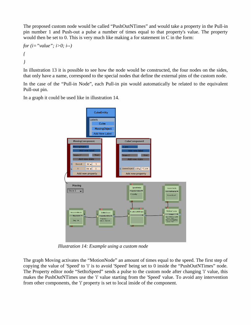
The proposed custom node would be called “PushOutNTimes” and would take a property in the Pull-in pin number 1 and Push-out a pulse a number of times equal to that property's value. The property would then be set to 0. This is very much like making a for statement in C in the form:
for (i=”value”; i>0; i--)
{
}
In illustration 13 it is possible to see how the node would be constructed, the four nodes on the sides, that only have a name, correspond to the special nodes that define the external pins of the custom node.
In the case of the “Pull-in Node”, each Pull-in pin would automatically be related to the equivalent Pull-out pin.
In a graph it could be used like in illustration 14.
The graph Moving activates the “MotionNode” an amount of times equal to the speed. The first step of copying the value of 'Speed' to 'i' is to avoid 'Speed' being set to 0 inside the “PushOutNTimes” node. The Property editor node “SetItoSpeed” sends a pulse to the custom node after changing 'i' value, this makes the PushOutNTimes use the 'i' value starting from the 'Speed' value. To avoid any intervention from other components, the 'i' property is set to local inside of the component.
Illustration 14: Example using a custom node
Proof of ConceptA small limited python based Entity System was made for the Blender Game Engine[5] with two game examples one done entirely with the current system[6] and one done with the Entity System made for the proof of concept[7]. This prototype allows using labels on Entities, represented by game objects, to apply logic from components, copy custom properties from the component and have local persistent values to this properties at Entity level. Entities are also represented by game objects, with the labels being represented by game object properties. This prototypes shows how an Entity System allows quick re usability, ease to modify shared logic and ease to reuse multiple game object related logic in comparison to the current system.
Sensors elements are used to simulate the sensor nodes and a python script is made to simulate a graph. The example also shows how runtime labeling allows to apply different components to the same object upon request, encapsulating logic. The most important test in the proof of concept uses the current logic bricks, being able to create sensors and actuators that are special to each game object inside the Component, and simply checking them through simple reference to the Entities. To do this, an explicit labeling system is made, which when is run, automatically creates the logic structure in a labeled Entity to be used through python scripting at component level. Because of the current Blender python API limits, only one component can copy sensor or actuator elements to Entities, but pure python based logic can be attached at runtime and without limitations. Also python pure logic can access other component's defined sensor and actuator elements defined in an Entity.
The example was made to compare the current system with the new proposed system in making a game. In the process of making a game, or any interactive content, it is common to want to change some behaviors, such as movement speed in a character, or adding more logic to a certain object or group of objects. The current system, without the use of python, is hard to modify and doesn't encourage tweaking logic applied to a group of objects, as it is common to have to apply changes manually to each object or change one object and copy the logic from that object to the others and make local changes to objects after that. There are ways to artificially make local logic of game objects more manageable, but the proposed solution would encourage to do reusable logic to beginners and make team work more manageable.
The proposed node-based syntax for logic has many similarities to the current game engine, but expands it by giving the ability to have explicit larger logic sequences and more options to the user to make logic more readable and modifiable.
Both the proof of concept using python and the current system are strong indicatives that a system like this would expand the current engines functionality related to reusability, visualization of logic and ease to modify logic.
ImplementationThis is a top level design that designs the user elements available to make programs and tries to give an inside on the strengths and functionality that make it an improvement over the current system. This proposal doesn't go into detail on technical implementation as it is focused on the user and not the underlying system, this means that the design is flexible enough to be implemented on other softwares and is not a Blender specific functionality. This is clear, as it is presented as a programming language design, and a programming language should not be platform specific.
It is proposed to make an iterative prototype driven implementation, making prototypes that allow to test the power and flexibility of the proposed functionality giving priority to the ease to change and expand prototypes over optimization, modifying the language upon finding problems or possible improvements and changing the prototype to meet the language requirements. Upon getting to a stage where the language is well defined and the prototype proves to be powerful enough, it is proposed to optimize the prototype or make a more optimized implementation based on the prototype.
ConclusionIn comparison to the current system, it would be very easy to make group of entities behave in a group manner. It would be very natural to make a multiplayer game separating the logic of the controllers with only a component or even with the initial values of properties and avoiding code duplication. It would also be straight forward to add a new functionality to many entities with less effort by only adding a new component to a label shared by the entities desired to have the behavior.
One of the problems with the new approach against the current is that as the design is to keep component modular and self contained, it is a little bit harder to directly relate the behavior of two objects in the game.
The proposed solution allows the reuse of visual code and it will be designed to be easy to read and understand also. The reuse of components with an entity system design allows to very easily import a component from one project to another and reuse it with very little work, allowing this in the future to manage bigger projects and share solutions with the community much easier. This is made possible by following the idea that a component must be self contained and that it cannot depend upon a certain kind of entity for it to work.
The most notable advantage in designing a game is the possibility to easily change the behavior of entities through relating components with entities by applying label changes. This doesn't limit to the functionality of the states in the current Blender Game Engine, specially because it allows explicit logic re-use and the language design pushes the developer into making the code re-usable.
References[1] Kleppe, Anneke. Software Language Engineering: Creating Domain-Specific Languages Using Metamodels. Adison Wesley, United States 2008.
[2] Martin, Adam. http://t-machine.org/ T-Machine Blog posts on Entity Systems. 2007 through 2010. http://t-machine.org/index.php/2007/09/03/entity-systems-are-the-future-of-mmog-development-part-1/
[3] Blender Foundation. Hierarchical Nodal Logic for Blender 2.5. 2009 through 2010. http://wiki.blender.org/index.php?title=Dev:Source/GameEngine/NodalLogic
[4] Ju An Wang, Andy and Qian, Kai. Component Oriented Programming. Wiley Interscience, Hoboken, New Jersey , United States 2005 .
[5] Proof of Concept, requires Blender 2.58 to be run:
http://wiki.blender.org/index.php/File:Dev-GSoC2011NodeEngine-ProofOfConcept-V0.6.blend#file
[6] Proof of Concept game example, requires Blender 2.58 to be run:
http://dl.dropbox.com/u/18587391/Dev-GSOC2011NodeEngineExampleNoNodes-v0.1.blend
[7] Proof of Concept game example with an Entity System, requires Blender 2.58 to be run:
http://dl.dropbox.com/u/18587391/Dev-GSOC2011NodeEngineExampleNodeSimulation-v0.1.blend