an energy management display for general aviation safety
TRANSCRIPT

An Energy Management Display for General Aviation Safety Enhancements
T. Adami, M. Uijt de Haag, Ohio University, Athens, OH E. Theunissen, Netherlands Defence Academy, Den Helder, The Netherlands
D. Sizoo, Federal Aviation Administration, Kansas City, MO R. McGuire, Federal Aviation Administration, Atlantic City, NJ
33rd Digital Avionics Systems Conference, Colorado Springs, CO

Outline
Introduction Problem Statement Research Objective
Technical Background definitions & symbology
Path and Energy Based Approach Guidance intercept tunnel energy cues
Implementation & Test Status part-task simulator flight testing
2

Problem Statement
Loss-of-Control (LOC) is the leading cause of fatal accidents Especially high for GA – 50% of all accidents Loss of energy-state awareness is a primary cause
CFIS continues to be an all-too-common result Number of vehicles in the NAS expected to triple by 2025 Increased traffic densities in NextGen will be achieved by reducing nominal separation.
3
Research Objective – Focus on GA
To develop, implement, and test a GA display that includes a dynamically generated path-way in the sky to provide GA pilots with flight path guidance during the arrival and approach phases of flight. The pilot can follow this desired path by lining up the flight path marker (FPM) with the center of the path. Simultaneously, the pilot can monitor the aircraft energy state and make efficient use of flight controls using energy cues added to the primary flight display (PFD).
4

Definitions: Flight Parameters
5

Definitions: Flight Parameters
6
FPV , ,f VFlight Path Vector:
The direction of the Flight Path Vector is indicated by the Flight Path Marker (FPM)
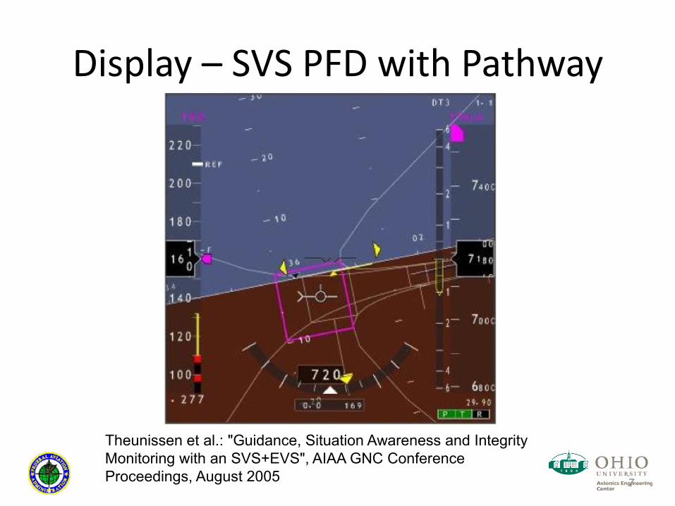
Display – SVS PFD with Pathway
7
Theunissen et al.: "Guidance, Situation Awareness and Integrity Monitoring with an SVS+EVS", AIAA GNC Conference Proceedings, August 2005
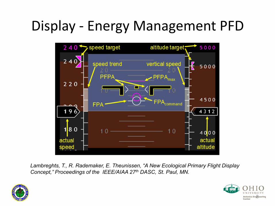
Display - Energy Management PFD
8
Lambreghts, T., R. Rademaker, E. Theunissenth DASC, St. Paul, MN.
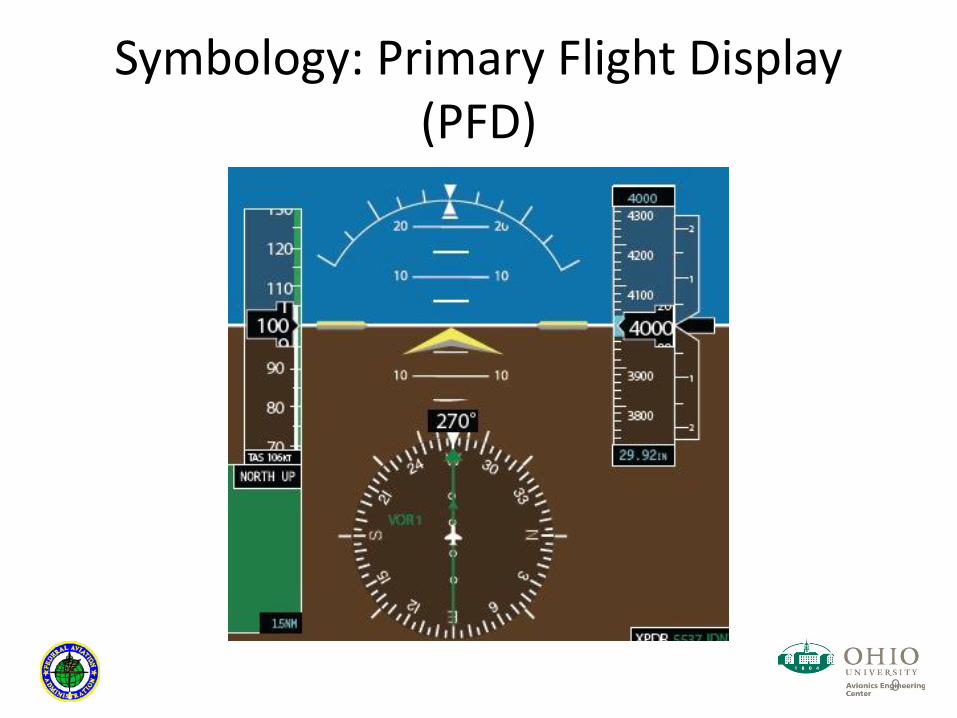
Symbology: Primary Flight Display (PFD)
9

Klopfstein Head-up Display (HUD)
10
Monagan, S.J. and R.E. Smith (1981). Head-Up-Display Flight Tests. Proceedings of the Fifth Advanced Aircrew Display Symposium, pp. 104-116, September 15-16, Naval Air Test Center, Patuxent River, Maryland.
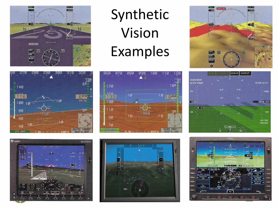
Synthetic Vision
Examples

Display: Energy-related Cues
12
PFPAmax
PFPAmin
Horizon
−10
−10
−
−
Waterline PFPA PFPA
Flight Path Marker (FPM)
SpeedError
Flight Path Angle: , Potential FPA
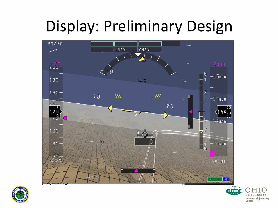
Display: Preliminary Design
13
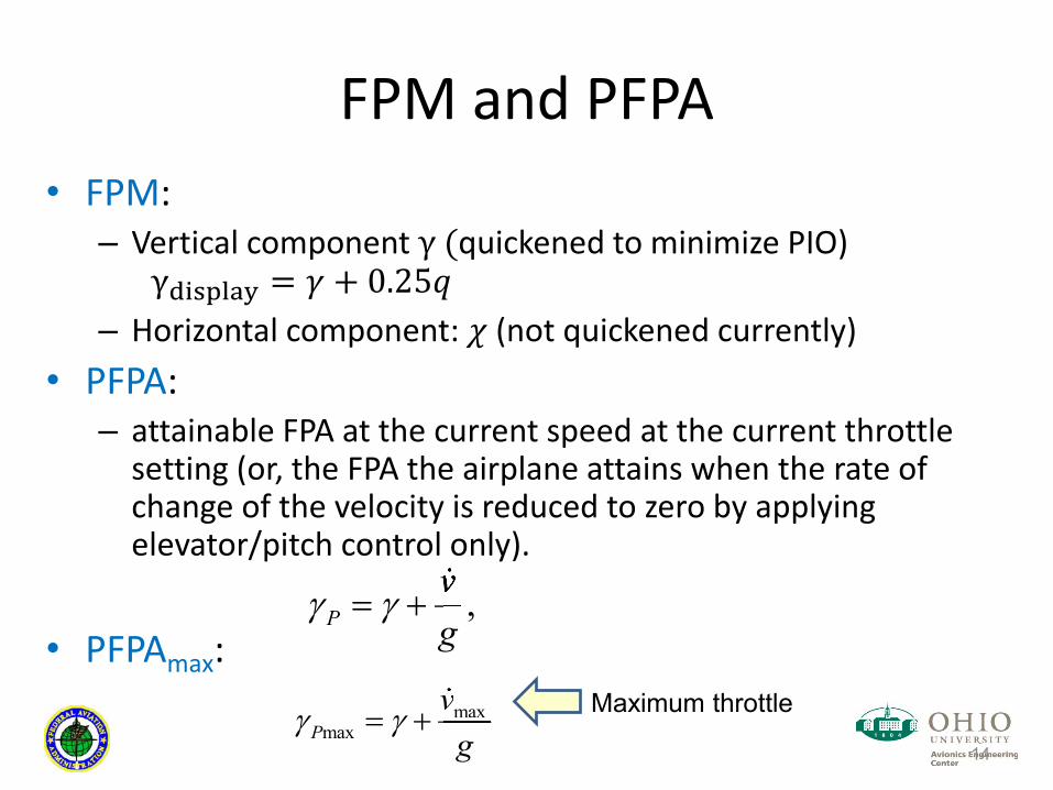
FPM and PFPA FPM:
Vertical component γ (quickened to minimize PIO) γ = + 0.25 Horizontal component: (not quickened currently)
PFPA: attainable FPA at the current speed at the current throttle setting (or, the FPA the airplane attains when the rate of change of the velocity is reduced to zero by applying elevator/pitch control only).
PFPAmax: 14
,Pvg
maxmaxP
vgmaxvm Maximum throttle

Dynamic Path* Generation
15
*GA arrival route and approach
Given these dependencies, the whole path can be generated dynamically if distance and height ℎ are defined.

Dynamic Path Generation: Rules Example rules for distance choice:
Spatially defined limit; Turn-radius defined limit based on current velocity and maximum bank angle; Turn-radius defined limit based on specified velocity and maximum bank angle.
Example rules for height choice: Current ownship altitude; Specified height above ground for downwind leg.
Additional constraints imposed on the base leg such as: Maximum glideslope angle ϒ2, or Maximum vertical speed,
16
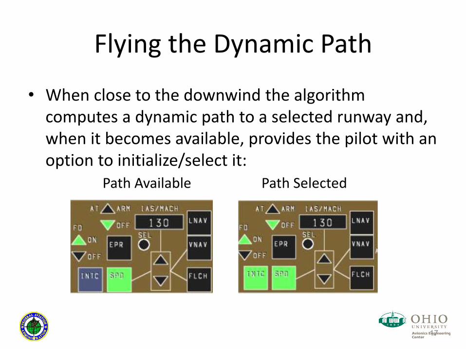
Flying the Dynamic Path
When close to the downwind the algorithm computes a dynamic path to a selected runway and, when it becomes available, provides the pilot with an option to initialize/select it:
17
Path Available Path Selected

Flying the Dynamic Path
FPM to fly the dynamically generated path; Additional velocity constraints drive the energy cues that must be monitored by the pilot;
E.g. V at point B should be between Vref and Vref+3kts, V at point A should be between Vref and Vref+1kts; aka energy funnel.
18

Implementation Example Dynamic paths into Johnson County Executive Airport (KOJC)
19
Entry Point to Approach Path (PFD) Approach Path on ND
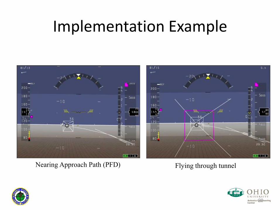
Implementation Example
20
Nearing Approach Path (PFD) Flying through tunnel

Implementation Example
21
Turning onto base leg Exocentric view of approach path
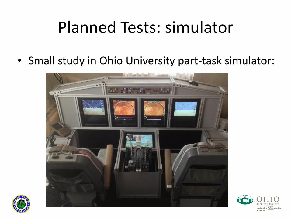
Planned Tests: simulator
Small study in Ohio University part-task simulator:
22

Planned Tests: flight test
Flight test at Ohio University and FAA with GA aircraft; Portable flight equipment: AHRS, GPS, Computer, Tablet, ADS-B, etc.
23

Summary
A synthetic vision display has been developed and implemented that provides dynamic generation of an arrival and approach path for a general aviation aircraft given a set of predefined constraint choices; Furthermore, energy state cues are included so the pilot can monitor its energy state along the flight path. Tests are currently being prepared in a fixed-base part-task simulator and GA aircraft (e.g. Cessna 172)
24

Thank You
Questions?
25