an electronic d.c. millivoltmeter - philips bound... · dynamic electrometer, philips tech. rev....
TRANSCRIPT

OCTOBER 1954 117
AN ELECTRONIC D.C. MILLIVOLTMETER
by A. L. BIERMASZ and A. J.MICHELS.
Electronic meters for measuring alternating current, comprising an amplifier, a rectifieranda moving.coil instrum~nt, are sufficiently well known. When such meters are precededbyD.C.-A.C. voltageconvertors, they can also be usedfor themeasurement ofD.C. voltages. In this way ameter of very high input resistance is obtained and the use of D.C. amplifiers is avoided.A meter designed along these lines is described in the following article. The objection tomany electronic meters - that they can be used only where A.C. mains are available -is eliminated by using dry batteries for the supply voltages.
This article describes an electronic D.C. voltmetersuitable for a wide variety of measuring rangesbetween 1 mV and 300 V. It can be used in place ofordinary moving-coil voltmeters and mirror galvano-meters. Compared with the latter it has the advant-ages of much greater robustness, better abilityto withstand overloads, and smaller inertia. Anadvantage of this instrument compared with con-ventional voltmeters is the very much higherinput resistance, which greatly widens the usefulscope. The input resistance is of the order of 1 MOin the lower measuring ranges and 100 MD in thehigher values. For a full-scale deflection of say 1 mV,the current taken is 1.5 X 10⁻⁹A, which correspondsto an input power of not more than 1.5 X 10¹² W.In contrast with most conventional electronic volt-meters the present instrument is operated from drybatteries, so that its usefulness is not limited toplaces where A. C. mains are available; one applica-tion in particular where this is a great advantage isin the use of strain gauges out of doors 1). Anotheruseful feature of this battery-operated instrumentis that measurements can be taken between twopoints which are both at a high potential withrespect to earth (with mains-operated meters thevoltage is limited by the breakdown field strengthof the insulation between the windings of the powertransformer); it is, of course, necessary to insulatethe meter itself.
When faced with the problem of constructing anelectronic D.C. meter the designer will probablyfirst turn his thoughts to a combination of D.C.amplifier and moving-coil instrument. With anordinary valve in the input stage a high input impe-dance is then obtained (109 ohms). In view of the
1) A. L. Biermasz and H. Hoekstra, Philips tech. Rev. 11,23·31, 1949/50.
621.317.321.027.21
required sensrtrvrty (full deflection on 1 mV) theunavoidable drift is then fairly great, viz. about0.3 mV per hour 2). Moreover, D.C. amplifiersnecessitate carefully stabilized supply voltages; inthe laboratory this is no obstacle, but in transport-able, battery-operated equipment it would certainlybe a problem.A better method consists in converting the D.C.
voltage to be measured into an A.C. voltage, andto measure this with an ordinary electronic A.C.meter consisting of an A.C. voltage amplifier, arectifier and a moving-coil instrument.There is a choice of two methods of converting the
D.C. voltage into an A.C. voltage, viz. the vibratingcapacitor or the vibrating contact.The first of these has already been described on
various occasions in this Review 3)4), the principlebeing as follows. The D.C. voltage to be measuredis applied to the vibrating capacitor with a highresistance is series with it. The capacitor itselfconsist of two plates, one fixed and one moving, withair dielectric. An moving coil loudspeaker unit fedfrom a valve oscillator vibrates the moving plate,thus producing aperiodic variation in the capacitance.In the same way as in capacitive microphones, analternating voltage is thus produced across thecapacitor, the amplitude of which is proportionalto the applied D.C. voltage.This method, too, has the advantage of a very high
input resistance (about 1010 ohms). It will give
2) A very much higher input impedance (1014 n) can beobtained with the electrometer triode (H. van Suchtelen,Philips tech. Rev. 5, 54·59, 1940), but the drift in thisinstrument is appreciably greater.
3) C. Dorsman, ApH meter with a very high input resistance,Philips tech. Rev. 7, 24-32,1942.
4) J. van Hengel and W. J. Oosterkamp, A direct-readingdynamic electrometer, Philips tech. Rev. 10, 338-346,1948/49.

U8 PHILIPS TECHNICAL REVIEW VOL. ie, No. 4
good results provided that the voltage to be mea-sured is not too small. If this is of the order ofmillivolts, however - and our meter is to besuitable for measuring fractions of a millivolt -difficulties are experienced owing to the fact thatthe vibrating capacitor produces an appreciableA.C. voltage even in the absence ofany D.C. voltage.This effect can be attributed to the small differencesin the work function of the materials of which thecapacitor plates are made 5). By making the platesof the same metal, which must be quite pure, we canreduce this effect to a few millivolts, but this isstill not low enough for our purpose and, moreover,the voltage is likely to rise owing to the entry ofdust and damp into the components; an instrumentused in the open air would be more than usuallyexposed to these.Preference has therefore been given to the vibrat-
ing-contact method. The contact periodically short-circuits the input of the A.C. amplifier and thusproduces a square-wave voltage, alternating betweenthe value to be measured and zero.The output current from the amplifier has to be
measured with a moving-coil meter and must accor-dingly be rectified, this latter being achieved bymeans of a second vibrating contact which opensand closes exactly in phase Ol' in antiphase with thefirst-mentioned contact.
IIIIII I
-~-II
Av-~- 0 [ ...£l..Jb d fa c e
Fig. 1. Block diagram of the D.C. voltmeter GM 6010. Zvariable attenuator (T-network). F low -pass filter. V, vibra-tor to convert the D.C. voltage to a square-wave voltage. AA.C. voltage amplifier. V2 vibrator to rectify the output currentof the amplifier. p.A microammeter. 0 oscillator for drivingthe vibrator.
a represents the D.C. voltage to be measured, includingripple. battenuator output voltage. c voltage at output offilter. d square·wave voltage. e amplifier output voltage.f half-wave rectified current passing through the meter.
The instrument further includes a variableattenuator for adjustment of the meter to thedesired measuring range, and a filter for suppressingany A.C. voltage that may be superimposed on theD.C. voltage (seeblock diagram, fig. 1).
5) See p. 28 of article 3).
The complete unit 6), the Type No. of which isGM 6010, is depicted in fig. 2; fig. 3a shows thebattery compartment and fig. 3b the chassis.
78849
Fig. 2. The millivolt.met er GM 6010. Left to right, attenuatorcontrol, zero adjustment (compensating current), gain correc-tion control, and multi-position switch for zero corrcction,measurement of the battery voltages, calibration, and reversalof polarity.
The vibrator
The contacts
The functions of the two vibrators illustrated infig. 1 are combined in a single flat spring whichalternately makes contact with contact screwsmounted on each side of it (fig.4).
In order to avoid errors in measurement, themaking and breaking must take place without anychattering, and the time taken by the spring totravel from the one contact to the other must beshort (about2%) compared with the complete period.To ensure that no chattering will take place, thevelocity at which the spring strikes the contact pointsmust be low 7). To ensure this, the contact screws aremounted near the clamped end of the spring wherethe amplitude of vibration is small and of a verydefinite value (about 10 [J.); the amplitude of thefree end of the spring is then about 0.5 mm. Thisarrangement also achieves a time of travel shortcompared to the time the contacts are closed.
6) The design of this meter was commenced by J. M. L..Ianssen, who has since left the service of the Company.
') Cf. J. A. Haringx, Vibration of contact springs, Philipstech. Rev. 7, 155-158, 1942.

OCTOBER 1954 ELECTRONIC D.C. MILLIVOLTMETER 119
7.&974
aFig.3. a) The meter GM 6010 showing the battery compartment. h) the chassis; Bl> B2 andB3 are the amplifier valves; B4 is the oscillator valve. V is the vibrator.
b
~--
@--
79005
Fig. 4. Cross section of the vibrator. and 2 are flat springsclamped at one end and maintained in vibration by an electro-dynamic driving system comprising coil 3 and permanentmagnet 4. The spring 1 makes contact alternately with screws5 and 6. 7 base plate; 8 housing; 9 rubber gasket.
3······5 6
--@
Whether contact is made and broken withoutchattering and whether the time of travel is suffi-ciently short, can be checked by means of the circuitshown in Jig. Sa in conj unction with a cathode-rayoscilloscope, which should then produce a tracesuch as that shown in fig. Sb.In the design of the vibrator the following possible
sources of measuring errors were taken into account:1) thermo-e.m.fs due to local heating at the contact
points 8).2) contact potentials set up by differences in the
chemical composition of the metals used for thevibrating contacts.
3) electrical double layers formed by the entry ofdust and moisture.
8) The faces of the contacts in unnsed vibrators are relativelysoft. Vibrators are "run-in" for some time in the factory:during this process the microscopically small projectionsfrom the faces are melted off, wbich suggests increases intemperature which are quite considerable though of shortduration. This running-in makes the contact faces smootherand harder, so that no further changes in shape take place.
TI
+E
O~----~~~----~L-I--~~
Fig. 5. a) Circuit for testing the vibrator; voltages +E and -E occur alternately acrossthe resistor T. The oscilloscope Dsc should show the image given in (b), without interferingpulses as in (c) and with a change-over time T equal to roughly 2% of the period T. Otherreferences as in fig. 4.
-t:v-
a
t-
b c 79006

120 PHILJPS TECHNICAL REVIEW VOL. 16, No. 4
These sources of error are minimized by takingthe following steps: the contact pressure is madesmall (i.e. very flexible contact spring), gold is usedas contact material (this is better than platinum orrhodium, for example), and the vibrator is made asairtight as possible.In this way it has been found possible to reduce
the residual voltage arising from the causes listedabove to 20 or 30 (LV,i.e. to a value that is somethousandths of that occurring with a vibr31tingcapacitor.The meter is provided with an adjustment for
eliminating the small' deflection resulting from thisresidual voltage (2 or 3 scale divisions); this is doneby passing a small variable compensating currentthrough the meter in the opposite direction.
Maintaining the vibrationThe simplest system whereby the vibrator can
be kept in motion is that of the ordinary tremblerbell. All that is needed is a solenoid with an addi-tional contact on the vibrating armature, the wholebeing fed from the source of filament current. Thissystem does not give satisfactory results however,as the armature spring readily assumes modes ofvibration other than the fundamental and thereforecannot be made to work without chattering.
11
~L
,""",-OOÖOOr- 79007
Fig. 6. Equivalent circuit of the vibrating coil. Zo = impe-dance of coil at rest.
We have accordingly adopted an electrodynamicdrive of the kind shown in fig. 4. Alternating currentfor the driving coil is supplied by a Hartley oscil-lator using a DAF 41 valve. The oscillatory elementis the coil itself, the equivalent circuit of which isdepicted in jig. 6. The total impedance Z of thiselement should be high at the resonance point, inorder to satisfy the condition of oscillation evenwhen the mutual conductance S of the oscillatorvalve is low; that is: SZ = constant.
The parameters C, Rand L in this circuit can be derivedfrom the mechanical data. Let us denote the moving mass by m,the spring constant bye, the damping factor by k, the velocityby v and the angular frequency by w. The force acting on themoving system in the stationary condition is then:
F = (jwm + k + .):._)v.Jwe
If we further denote the terminal voltage of the coil bye,the induced electromotive force by ei, the impedance of thecoil at rest by Zo and the 'current by i, then:
Also:e = iZo - ei. (2)
F =F.. ai (3)and: ;,: . "",
èj=-av, (4)
where a = Bl, B being thjl m~gnetic induction in the air-gap,and l the length of wire in the coil.
Eliminatien of F, v ~n~tei from (1), (2), (3) and (4) givesthe impedance Z of the ecrU;,". :~..
e . J 1Z = -;-= Zo'·+-l k• t ,. "I;; m 1
, ~! jw - + - + --. , "li~, a2 a2 jwca2
• A'" '.'c·y; f,
From this and from fig:,6 it.follows that C = m/a2, R = a2/kand L = ca2• At resonance, wm/a2 = l/w ca2, so that the reson-ance frequency is determined by mc, and Z becomes Zo + a2/k,where Zo is approximately the D.C. resistance of the coil. Foreasy oscillation a2/k should be high, i.e, a high (strong mag-netic field, many turns), and k small (weak damping).
For our purpose the self-inductance L in theequivalent circuit is 0.25 H and the capacitance Cis 20 (LF, which gives a resonance frequency ofabout 70 cjs. At this low frequency the impedanceof the coil at rest, Zo, is almost that of a resistanceof 800 ohms. The total impedance of the coil vibra-ting at its own natural frequency is roughly 7000ohms, so that oscillation will occur even when themutual conductance of the valve is low. This highimpedance was attained by adopting variousmeasures to reduce the damping; the air dampinghas been kept low by using a streamlined coilformer with perforations. Owing to the flexiblesuspension, moreover, there is very little lossthrough a transfer of energy to the framework. Theinput power of the coil is only a few milliwatts.
The amplifier
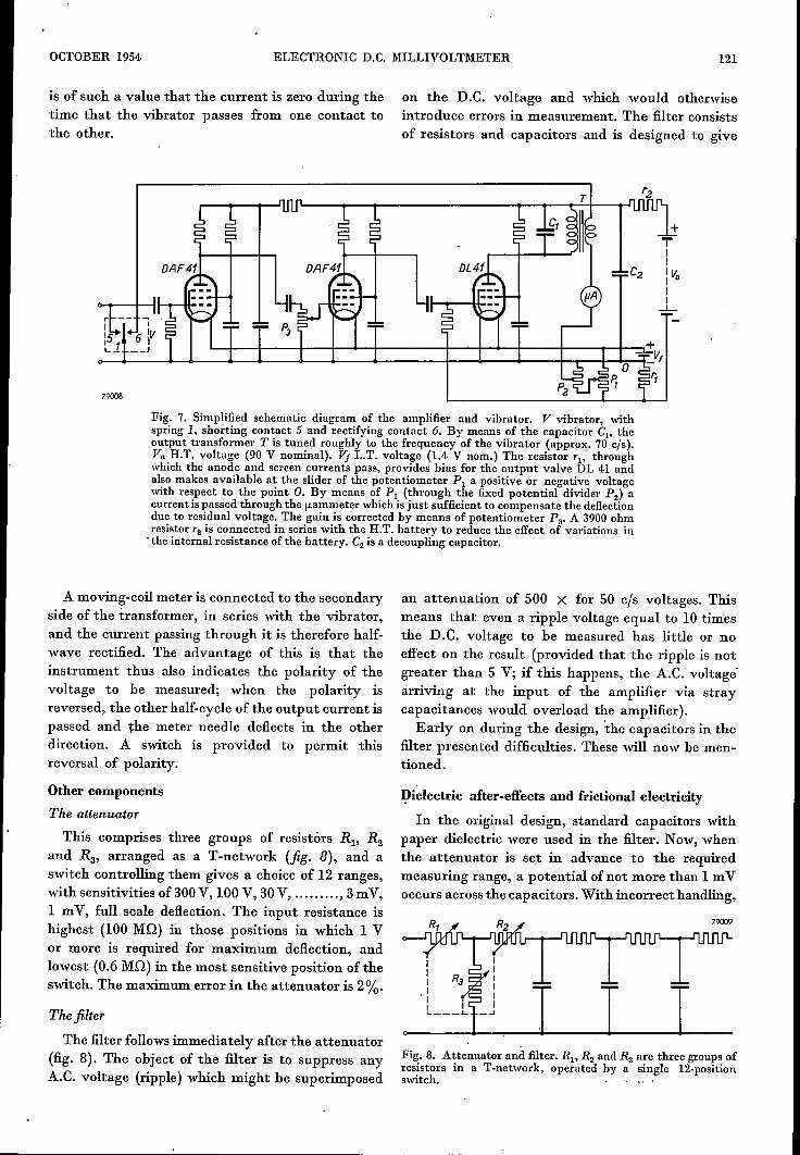
A three-stage amplifier is used, with DAF 41valves in the first and second stages and, in view ofthe desired linearity, a DL 41 9) as output valve(jig. 7).The anode circuit of the output valve includes a
transformer whose core is provided with an air-gapto avoid D.C. saturation, which would affect thelinearity of the scale. By means of a parallel capac-itance, the primary side of the transformer is tunedroughly to the frequency of the vibrator, so that,although the input voltage is of square wave-form,the output voltage is practically sinusoidal.
This parallel capacitance affects the phase of theoutput voltage. To ensure effective rectification, it
(1) 9) The DL 41 valve is discussed in Philips tech. Rev. 10,346-351, 1948/49.
OCTOBER 1954. ELECTRONIC D.C. MILLIVOLTMETER 121
Fig. 7. Simplified schematic diagram of the amplifier and vibrator. V vibrator, withspring 1, shorting contact 5 and rectifying contact 6. By means of the capacitor Cl' theoutput transformer T is tuned roughly to the frequency of the vibrator (approx. 70 eis).Va H.T. voltage (90 V nominal). Vj L.T. voltage (1.4 V nom.) The resistor rl, throughwhich the anode and screen currents pass, provides bias for the output valve DL 41 andalso makes available at the slider of the potentiometer Pl a positive or negative voltagewith respect to the point O. By means of Pl (through the fixed potential divider P2) acurrent is passed through the fLammeterwhich is just sufficient to compensate the deflectiondue to residual voltage. The gain is corrected by means of potentiometer Pa. A 3900ohmresistor r2 is connected in series with the H.T. battery to reduce the effect of variations in.the internal resistance of the battery. C2 is a decoupling capacitor.
is of such a value that the current is zero during thetime that the vibrator passes from one contact tothe other.
79008
A moving-coil meter is connected to the secondaryside of the transformer, in series with the vibrator,and the current passing through it is therefore half-wave rectified. The advantage of this is that theinstrument thus also indicates the polarity of thevoltage to be measured; when the polarity isreversed, the other half-cycle of the output current ispassed and the meter needle deflects in the otherdirection. A switch is provided to permit thisreversal of polarity.
Other components
The attenuatorThis comprises three groups of resistors RI' R2
and R3, arranged as a T-network (fig. 8), and aswitch controlling them gives a choice of 12 ranges,with sensitivities of 300V, 100 V, 30V, ,3 mV,1 mV, full scale deflection. The input resistance ishighest (100 MO) in those positions in which 1 Vor more is required for maximum deflection, andlowest (0.6 MO) in the most sensitive position oftheswitch. The maximum error in the attenuator is 2%.
Thefilter
The filter follows immediately after the attenuator(fig. 8). The object of the filter is to suppress anyA.C. voltage (ripple) which might be superimposed
on the D.C. voltage and which would otherwiseintroduce errors in measurement. The filter consistsof resistors and capacitors and is designed to give
an attenuation of 500 X for 50 cis voltages. Thismeans that even a ripple voltage equal to 10 timesthe D.C. voltage to be measured has little or noeffect on the result (provided that the ripple is notgreater than 5 V; if this happens, the A.C. voltage'arriving at the input of the amplifier via straycapacitances would overload the amplifier).Early on during the design, the capacitors in the
filter presented difficulties. These will now be men-tioned.
Dielectric after-effects and frictional electricity
In the original design, standard capacitors withpaper dielectric were used in the filter. Now, whenthe attenuator is set in advance to the requiredmeasuring range, a potentialof not more than 1 mVoccurs across the capacitors. With incorrect handling,
Fig. 8. Attenuator and filter. RH R2 and Ra are three groups ofresistors in a T·network, operated by a single· 12-positionswitch.

.-------------------------------- ~~
122 PHILIPS TECHNICAL REVIEW VOL. 16, No. 4
however, for example when a 100 V potential is tobe measured and the instrument is set for maximum1 mV, the voltage on the capacitors can be verymuch higher. The instrument is able to withstandthis (because the gain drops considerably on over-loads), but thè real difficulty was found to be thatthe discharge of the capacitors takes place veryslowly, necessitating an hour's wait before theinstrument is again ready for use. .
This can be demonstrated by the following experi-ment. A paper capacitor, of capacitance C = 0.22{lF, is charged up to 100 V and is then dischargedthrough a resistor R= 1.68 MO. At first the voltagewill- drop in accordance with the anticipatedexponential curve with time constant RC = 0.37sec, until a value of about 1 mV is reached. Thefurther voltage drop, which is shown plotted infig. 9, takes place much more slowly: as an approxi-mation, exponentially with a' time constant of165 sec, i.e. roughly 500 RC. It takes about anhour for the voltage to drop to 10 fLV (= onedivision of the scale of the GM 6010). Short-circuiting of the capacitor does not help matters,because as soon as the short is removed, roughlythe same voltage occurs again (seeA and B, fig. 9).
700pV
1655
79010
°OL__L--L_~~L_~--~LLJ-L-~--2 3 4 9mln
t-Fig. 9. Dielectric after-effect in a paper capacitor charged to100 V and discharged through a resistor (time constant RC=0.37 sec). The figure shows the drop in the capacitor voltagefrom the moment it reaches 650 !LV.vc then diminishes muchmore slowly than before, more or less exponentially, with atime constant of about 165 sec. Even when the capacitor isshort-circuited for different lengths of time (at A and B), thevoltage vc returns to roughly the same value after the short isremoved.
This is due to a kind of after-effect; ions areproduced in the dielectric which can disappear onlyslowly. Some materials exhibit this property to amuch smaller extent than others; in polystyrene,for example, the effect is very slight indeed andpersists for only about 1/50 the time as in paper.For this reason filter capacitors with polystyrenedielectric are used in the GM 6010.
As the insulating material used for the terminalblocks would also be likely to exhibit this effect,polystyrene is used for this purpose as well. .
Another source of interference is to be found infrictional elèctricity generated on the insulatingmaterialon the connecting leads, particularly if thisis of plastic. Static charges may be set up by friction,flexion or vibration, and these will produce a de-flection. Because of this, rubber-covered flex, or,better still, bare leads, if necessary supported byceramic insulators, are used.
Calibration
For preference, electronic meters should beequipped with means for self-calibration. Thisapplies all the more when the instrument is operatedfrom dry batteries, whose voltage may vary consi-derably, and when the amplifier, as in the GM 6010,does not use negative feed-back.. In the first place the supply voltages of theinstrument are checked to see that they are withinthe appropriate limits. This is done using the movingcoil meter which, with the calibration control setto certain positions, functions as an ordinary volt-meter. The H.T. battery should give a readingbetween 95 and 75 V, and the filament cell between1.55 and l.05 V.
Calibration is effected as follows. A potentialdivider of fixed resistors delivers a certain fraction(I/A) of the L.T. voltage Vj. With the calibrationcontrol rotated one stage, this voltage Vj/A isapplied to the input of the vibrator, the gain beingthen so adjusted by means of the gain control(potentiometer P3' fig. 7) that the meter indicatesVj, i.e. the same deflection as with direct measure-ment of the L.T. voltage. It is then known that thegain is equal to the fixed value A on which the scalecalibration is based.
Summary Description of an eleetronic D.C. millivoltmeter (typeGM 6010), in which the D.C. voltage to be measured is con-verted by a vibrator into a square-wave voltage which is sub-sequently amplifiedby an A.C. amplifier. A second contact onthe vibrator rectifies the output current from the amplifier,andthis rectified current is passed through a moving-coil meter.The vibrator is driven by an electrodynamic system in whichthe coil constitutes part of a valve oscillator. The amplifier andoscillator are operated from dry batteries, and the use of theinstrument is therefore not limited to places where A.C. mainsare available. As the meter is independent of the mains, volt-ages can be measured between points which are both at a highpotential with respect to earth. The vibrator circuit is precededby a variable attenuator and a filter; the former has 12positionscorresponding to ranges of 300 V, 100 V, 30 V 3 mV.1 mV. The input resistance lies between 100 MO for rangesof 1 V and upwards and 0.6MO for 1mV; the filter suppressesA.C. voltages that may be superimposed on the D.C.voltageto be measured. Polystyrene is used for the dielectric of thefilter capacitors as well as for the terminal blocks. as thismaterial showsvery little electrical after-effect. The instrumentis provided with means for self-calibration.