an earth liberation front guide - independent media center
TRANSCRIPT

Setting Fires With Electrical TimersAn Earth Liberation Front Guide
May 2001
2
Do not shorten any of the recipes. They have been carefully worded to avoid mistakes andconfusion. If you need to retype recipes, please carefully check your work. Typos and omissionscould cause timers to fail and expose saboteurs to needless risks.
Setting Fires with Electrical Timers, An ELF GuideMay 2001 edition, PDF versionCopyright � 2001 by F.C. (Fireant Collective)
The PDF version is slightly different than the paper version. An introduction has been added tothe PDF version. Step 2 of the Model Rocket Igniter recipe has been expanded. All otherdifferences between the versions are cosmetic.
Permission to copy is granted to all nonprofit groups working for animal liberation and theirsupporters. Permission to copy is also granted to bookstores that specialize in animal rights,environmental and anarchist literature. You may charge a fair price to cover copying expensesand labor. If you fit this criteria:
Please copy and distribute this manual.All other corporations, companies, businesses, institutes, colleges and think tanks are forbiddenfrom copying this publication in part or whole. All government agencies and employees of thegovernment are expressly forbidden from copying this publication in part or whole. Violators willbe subject to prosecution or retribution. You’ve been warned.
3
Table of ContentsTerminology............................................................Four Rules of Arson................................................Where to Put Incendiary Devices............................Fuel Requirements for Buildings............................Putting an Incendiary Device Together...................The Bucket-Igniter Connection...............................Creating a Clean Room...........................................Tips for Constructing Electrical Timers..................Bullet Connectors vs. Alligator Clips......................How to Solder..........................................................Read the Instructions Carefully...............................
Recipes:� Old-Fashioned Kitchen Timer..........................� SCR Digital Timer............................................� Model Rocket Igniter........................................� Light Bulb Igniter.............................................
Electrical Timers in Cold Temperatures.................Keeping the Igniter Dry..........................................Where to Get Started..............................................
445677910121314
15193032
353637
IntroductionElectrical timers are superior to delays that use candles, incense or cigarettes. Electrical timers have
significantly longer delay times. When electrical timers are carefully constructed, they are more reliable. Each onecan be tested repeatedly until you are certain that it will work. Electrical timers are easily protected from wind andrain, whereas even a mild breeze can be a problem for candles and incense.
This guide has recipes for two electrical timers, the Old-Fashioned Kitchen Timer and the SCR Digital Timer.Both recipes have been greatly expanded to give extremely clear and detailed instructions. Our goal has been toeliminate ambiguity from the directions and to provide as many helpful tips as possible. You don’t need priorexperience with electronics. You need only practice some with a soldering iron. As long as you pay attention todetails and do the proper testing, you’ll be able to construct highly reliable timers.
The Old-Fashioned Kitchen Timer is relatively quick and easy to construct. The SCR Digital Timer takesmuch longer to build, especially the first few times, but it is worth the effort. At the target, it can be positionedand activated with unparalleled speed and safety. In addition, the SCR Digital Timer is extremely precise – downto the minute, and even down to the second, depending on the timepiece. With that level of precision, you canguarantee that multiple incendiary devices will ignite at the same time. Simultaneous ignition is especiallyimportant in situations where you expect firefighters to arrive quickly. If ignition is not simultaneous, the first firemay bring firefighters onto the scene before the other fires have a chance to do damage.
There are two other timer recipes that have been passed around. Both have serious drawbacks and should nolonger be used. One recipe uses the hour hand on a wind-up wristwatch to push two wires together. It is terriblyimprecise and most wristwatches are unable to perform the job. The other recipe uses an alarm clock that plugsinto an electrical outlet. (It must be an alarm clock with a battery backup.) This type of alarm clock shuts off itsdisplay when unplugged, creating complications for the saboteur. Another problem is its reliance on a REEDrelay, which is not a solid state component and not as resilient as an SCR. The SCR Digital Timer is morefoolproof and easier to use.
We hope you find many good uses for these timers. Enjoy.

4
TerminologyACCELERANT – A substance, usually a liquid, which releases tremendous heat when it burns. Accelerant actslike a shot of adrenaline: it dramatically increases the pace of destruction. Petroleum products such as gasoline,diesel and kerosene are very powerful accelerants.
IGNITER – The intermediate component between a timer and the accelerant. The igniter creates a hot flame whentriggered by a spark, a smoldering ember, an electric current or some other heat source coming from the timer.The igniter must burn long enough and hot enough to set the accelerant on fire.
TIMER – Chemical, mechanical or electronic mechanism that causes a time delay before a fire erupts. Examplesinclude fuses, candlewicks, cigarettes, incense, modified kitchen timers, and modified alarm clocks.
INCENDIARY DEVICE – A system consisting of an igniter and a timer and a quantity of accelerant.
PREMATURE IGNITION – The potentially dangerous situation when an incendiary bursts into flame before it issupposed to. (Usually followed by the words, “Oh shit!”)
Four Rules of Arson1) Most of the heat from a fire rises. Convection currents cause flames and heat to travel upwards. When
choosing locations for accelerant, consider the path of rising heat as the accelerant burns. Get as much of thatrising heat into the “target area” as possible. The target area is that part of the building or vehicle which ismost vulnerable to fire. (For most buildings, the target area is the attic and its rafters, as described in the nextsection.)
2) The heat needs to be concentrated in one place. It is counterproductive to disperse the accelerant. Containthe accelerant by keeping it in a 5-gallon bucket or other container. Hollywood movies often show peoplesplashing gasoline everywhere before setting a fire. This creates a nice special effect as flames leap up allover the place. However, the heat is dispersed which makes it less likely that solid wood will absorb enoughheat (energy) to catch fire and stay on fire.
3) The heat needs to be sustained over a period of time. As an object is exposed to heat, more and more ofthat energy will be absorbed over time. The temperature of that object will eventually reach the point wherecombustion (fire) can occur. A momentary flash of intense heat, like a ball of fire, is not as likely to transfersufficient heat to the object as would a steady flame. For example, you won’t be burned if you move yourhand quickly through a candle flame. This is not true if you hold your hand still in the flame. Even very hightemperatures can be rendered ineffectual if there isn’t enough time to transfer sufficient heat. This occurs withgasoline which burns hot and fast. Diesel is added to gasoline to slow down the burn rate.
4) Guarantee destruction of the target through careful planning and execution. Take no shortcuts. Dothorough reconnaissance to eliminate surprises. Make contingency plans for anything that could go wrong. Doextensive testing of timers and igniters. Use multiple incendiary devices with generous amounts of accelerant.Never be satisfied with possible destruction or probable destruction. The objective of every action should beassured destruction. The risks are too high for anything else.

5
Where to Put Incendiary DevicesTo successfully destroy a building, the saboteur must burn through the rafters that support the roof. Any walls
that escape the fire will be of no value if the roof collapses. So don’t be concerned about how much damage isdone at the ground level. The goal is always to move the fire up into the rafters. It is essential that the fire destroyenough of the ceiling joists to make the roof structurally unsound. Proper placement of incendiary devices willdirect the fire across numerous ceiling joists.
Always place incendiary devices against at least two different walls. This is necessary for cutting acrossceiling joists. This also creates a draft that speeds up the fire by giving it more oxygen.
Determine the exact location for each incendiary device before the night of the action. Take advantage of anyfeature of the building that will contain the heat of the burning accelerant and move that heat into the structure.Consider the path of rising flames and rising heat (convection currents). Also consider where heat will be radiatedas a surface burns – will it radiate heat out into the atmosphere (bad) or towards a nearby surface that is alsoburnable (good).1) A porch roof traps rising heat extremely well. The roof above a porch is not as high as the main roof. And the
exposed wood underneath the porch roof will be dry. Place the incendiary device up against the wall of thebuilding so that the fire will be immediately positioned to enter the main structure. The only disadvantage toplacing an incendiary device on the porch is that it will be more noticeable if a security guard enters thebuilding or is checking that all the doors are locked.
2) A recessed entranceway, especially if it’s recessed several feet, is the perfect situation. The heat is reflectedand absorbed by the building on three sides. Rising heat is channeled directly into the structure, which onsingle story buildings is the attic area. The only disadvantage is the increased chance of discovery if a securityguard comes by.
3) An overhanging roof (known as a “soffit” in theconstruction trade) captures the heat as it rises. The morethe roof overhangs, the better. There may be a series ofventilation holes beneath an overhang, with tiny screenscovering the holes. If you see ventilation holes, you are inluck and you should definitely place incendiary devicesdirectly beneath them. Ventilation holes greatly acceleratethe process of getting fire into the rafters. When there is anoverhanging roof, utilize either an “inside corner” or awindow to get even more heat into the structure.a) An “inside corner” is found on the exterior of a
building where two wings of an L-shaped buildingcome together. A T-shaped building will have twoinside corners. The incendiary device is placed in thecorner up against the walls. The heat will be reflectedback and forth between the walls and channeledupwards, enhancing your fire. An inside corner worksbest when there is also an overhanging roof. If there isno overhang, a lot of heat will be lost to theatmosphere.
b) A medium-sized window and an overhanging roof are a good combination. Place the incendiary devicebeneath the window. The heat from the flames will break the glass. Some of the heat will go through thebroken window into the room and some of the heat will be absorbed by the overhang. If anotherincendiary device is placed at a second window (perhaps on the opposite side of the room), then a nicedraft will give the fire plenty of oxygen. Without an overhanging roof, most of the heat from anincendiary device placed outside a window will be lost to the night sky.
To summarize: any recessed area, nook, soffit, porch, or ornamental roof can be used to your advantage. Allof these concentrate and/or capture the heat of the accelerant. A plain wall without an overhanging roof is the
Figure YY: Cross section of a roof,showing flames entering through a soffit.

6
worst situation. In this case look for a shed, a neighboring building, a parked car or a dumpster that is closeenough to reflect heat back towards your fire. Some dumpsters can even be moved around into a good position.
The typical A-frame is known as a gable roof (see the first building depicted in Figure ZZ). Two sides of thebuilding will have eaves where the roof overhang is close to the ground (a good location for incendiary devices).The remaining two sides, called the gable ends, have a roof overhang that becomes progressively further awayfrom the ground towards the center of the wall (a bad location for incendiary devices). You want the fire to hit thebottom of the rafters, so it can climb up the entire length of the rafters and fully engulf the roof. For three of theroof types – the gable, the gambrel and the lantern – in Figure ZZ, you can identify the worst location for anincendiary device by where the artist has drawn the door.
It is important to consider how visible the incendiary devices will be to security guards and passersby. Takeadvantage of shadows and shrubbery to hide them. If just one device is discovered prior to ignition, the wholeoperation will fail.
Fuel Requirements for BuildingsFor a small single story building, the prescription is two incendiary devices each using 5 gallons of accelerant.
If the building is larger than a summer cottage, then use additional incendiary devices with 5 gallons of accelerantfor each device. Always target at least two walls. For guaranteed total incineration, space the devices at 20 or 30-foot intervals along these walls. In the case of a long sprawling building, it may be impractical to envelope thewhole building in flames, but careful placement of incendiary devices could destroy enough of the structure torender it effectively worthless. Or the fire could be focused on the most expensive areas (e.g. computers, labequipment).
A two-story building requires more fuel at each ignition point to push your fire the extra ten feet up to therafters. Use 8 to 10 gallons for each incendiary device. Also adjust the gasoline-diesel ratio to include moregasoline and less diesel which will project the flames higher.
A three-story building is too high to project flames all the way up a plain wall into the roof. Instead, you mustutilize a recessed door, a low roof above a porch, or a crawlspace to get the fire into the building.
It is usually unnecessary and a waste of precious time to gather up flammable materials at the scene (e.g.fenceposts, branches, wooden furniture). It is much more valuable to bring more fuel if you are concerned aboutthe success of your fire. Gasoline and diesel are perfectly suited to delivering large quantities of heat, not too fastand not too slow.
If carrying a lot of fuel is unfeasible, the amount of accelerant per device can be reduced from 5 gallons to 3gallons. But don’t use less than 3 gallons per device. And don’t use less than 9 or 10 gallons total for anybuilding. In other words, the absolute minimum is 3 gallons of accelerant at three different locations or 5 gallonsof accelerant at two locations. Remember the rule: always strive for guaranteed destruction.
Figure ZZ: Roof Types

7
Putting an Incendiary Device TogetherEach incendiary device is composed of three parts: the timer, the igniter, and the accelerant. For safety, the
three parts are kept separate from one another while being transported. At the specified time, electrical timerssend an electric current to the igniter. The purpose of the igniter is to convert the electric current (or smolderingember) into a flame and to feed that flame so that it is capable of catching the accelerant on fire.
Without accelerant, timers and igniters could offer nothing more than a brief flame and a puff of smoke.Accelerant is what turns a tiny fire into an inferno. According to tradition, accelerant should be 50% gasoline and50% diesel. There is no need to measure out the ratio precisely, just mix roughly half gasoline and half diesel. Ifyou have trouble getting diesel, it’s o.k. for the accelerant to be entirely gasoline. It is not o.k. to use less than halfgasoline for any reason, because gasoline is necessary for ignition. Diesel is reluctant to catch fire. Even a burningcandle can be extinguished by pouring diesel on top of it. Gasoline ignites readily, then heats up the diesel andgets it burning.
Use a plastic 5-gallon bucket to hold the accelerant. A 5-gallon bucket has a convenient handle and a tight-fitting lid. It is cheaper and looks less suspicious than a red gas can. The flat top of the 5-gallon bucket is an idealshape for positioning the igniter to melt through the lid (as described in option 2 below). The wide diameter of thelid is ideal for leaving the lid off and immediately exposing the accelerant to a good amount of oxygen (asdescribed in option 1 below). Buckets are discarded regularly by restaurants, but you’ll have to check that the lidsfit properly. New buckets with matching lids can be purchased at hardware stores. Get buckets with handles.Some buckets are 3 or 4 gallons but are similar to 5-gallon buckets in all other respects.
You will need to use an approved gas can to get the fuel at a gas station. Filling other types of containers at agas station is forbidden by law and will draw unwanted attention. To minimize leakage, leave about 3 inches ofair space whenever you fill gas cans or 5-gallon buckets. (Gas cans usually have a recommended fill line markedon them.)
The Bucket – Igniter ConnectionThree options are given below for how to position the igniter next to the container(s) of accelerant. It is
important to use the same option for all the incendiary devices at a particular target. By using the same option,you greatly increase the likelihood that the incendiary devices will reach their full force at the same time.
Option 1: Position the igniter above a 5-gallon bucket with its lid removed, giving the igniter directcontact with gasoline vapors.
Advantages: A very large flame is instantly produced, which is very important if firefighters are going toarrive quickly. Only one container of accelerant is required for each incendiary device.Disadvantages: Extra time at the target is needed to remove the lid. Safeguards must be taken to avoidpremature ignition. Gloves may get slightly contaminated with accelerant.At the target, set the 5-gallon bucket at the desired location, then remove its lid. Some lids pop off simply by
lifting on tabs. Other lids can be removed only by making cuts in the side of the lid at regular intervals. The cutsare made in the narrow grooves where the plastic is thin. If you are uncertain about what needs to be done, find aused lid behind a restaurant and examine how it was cut off. The knife needs to be very sharp, so use a razor bladeknife with a new razor. Afterwards, dispose of the razor blade and wash the knife.
The igniter must be suspended above the bucket. Here are two methods that are easy, cheap, lightweight andtake up relatively little room for easier transport. The first method is to tape the igniter to two sticks that areslightly longer than the diameter of the bucket. The sticks must be fingerprint-free. Beware: older, drier sticks arebrittle and susceptible to breaking. Position the sticks parallel to each other and tape the igniter between them.
Another method of positioning the igniter above an open bucket is to use a second lid with a large, pre-cuthole. Make the hole as large as possible while still retaining rigidity and enough space to lay the timer and igniter
8
on it. After setting the bucket at the desired location at the target, remove the intact lid and lay the modified lid inits place. If desired, the timer and/or igniter can be pre-taped to the lid.
Do not place the incendiary device in a closet or other confined space. Gasoline is constantly giving offvapors. Over time the concentration of vapors in a small, enclosed space may become too great for the incendiarydevice to work. In technical terms, the ratio of gasoline vapors to air must not exceed “the upper flammable limit”for gasoline (7.6%), otherwise the gasoline will not burn even with a flame right there.
It would be a mistake to think that the flare is an unnecessary part of the igniter when using this option. Thesustained heat from the flare (as opposed to the brief flame from the matchbooks) is important in certain situationsinvolving stagnant air.
DANGER: Premature ignition is a serious concern. Do not remove the lid of a 5-gallon bucket in the vicinityof heating or air conditioning units or anything else that could make even a small spark. There are many thingsindoors that make sparks (e.g. computers, refrigerators, ringing phones, fax machines, etc.). You also have towatch out for pilot lights on gas appliances. Unless your group is very experienced at setting fires, we urge you tokeep accelerant in closed containers and use one of the other options when working inside a building.
Option 2: Position the igniter to burn through the lid of a 5-gallon bucket.Advantages: It is extremely fast to set up. Only one container of accelerant is required for each incendiarydevice.Disadvantages: The flame starts off small and grows slowly.Set the 5-gallon bucket at the desired location. Leave the lid on. Lay the timer and the igniter on top of the lid.
The flare must point down slightly, allowing the flame that shoots out the top to contact the plastic. To get theflare pointing down, set the non-burning end of the flare on the raised edge of the lid. If the non-burning endneeds to be raised even more, set a block of wood under it. Instead of a block of wood, you could tape a bunch ofmatchbooks together, setting one on top of another until the necessary height is achieved. Then tape the bundle ofmatchbooks to the non-burning end of the flare. Matchbooks are cheap and can be acquired in large packs withoutfingerprints.
When the flare ignites, it will burn a hole in the lid and ignite the gasoline vapors. The hole in the lid willgradually increase in size.
Option 3: Tape the igniter to a milkjug with the flare positioned to melt through the milkjug.Advantages: It is the most reliable option because the matches will melt through the milkjug even if the flaredoesn’t light.Disadvantages: Two containers of accelerant are needed. The flame starts small and it takes longer than theother two options for the flame to reach full size.A one-gallon milkjug or a one-gallon jug of spring water is filled with 100% gasoline. Do not add diesel to
the milkjug because diesel has the potential to smother flames without catching fire. To prevent leakage, fill themilkjug only ¾ full, leaving the top quarter as air space for vapors to collect. The lid must screw on instead ofpopping on. Using a container with a pop-on lid will lead to an awful mess in the transport vehicle. Tape theigniter to the milkjug. The burning end of the milkjug should be inside the handle. More precisely, the matchheads should be underneath (and very close to) where the handle connects with the jug.
At the target, set the milkjug next to a 5-gallon bucket filled with 50% gasoline and 50% diesel.
WARNING: Do not suffocate the incendiary device by leaving it in a closed daypack, duffelbag, cardboard box or other container. The matches and the road flare don’t need access tooxygen, but the accelerant does.

9
Creating a Clean RoomThe following precautions may seem extreme, but the technology of DNA matching has pushed us into a
whole new era and the full impact has yet to be felt. During the 1990s, crime labs needed a sample that hadhundreds of cells to be able to get a DNA print. Researchers have announced success with new techniques thatrequire only a single cell as the sample. This technology will soon be in the crime labs if it’s not already. Withthis advance, investigators can use a microscopic skin flake instead of needing a whole drop of blood or saliva.And humans are constantly shedding skin flakes.
To set up a clean room, choose a location where your hair and skin flakes are not already floating around. Thelocation should also be free of hairs from a dog, a cat or another animal companion that the government wouldconsider to be “your pet.” Use a friend’s basement or garage (someone who is not politically active). Or rent amotel room. Another option is to set up a tent in the woods. Use a brand new tent and keep someone outside thetent as a lookout. Since there are no electrical outlets in the woods, you’ll need to run the soldering iron off a DCto AC inverter that plugs into your vehicle’s cigarette lighter. Or get a butane-powered soldering iron at RadioShack. After constructing the timers & igniters, you can return the tent (in a distant city).
Before entering the clean room, cover as much skin as possible. Get long pants and a long-sleeved shirt at asecond-hand store. Don’t wear these clothes until you are ready to enter the clean room. Dispose of them after youhave finished constructing the timers & igniters. A disposable painter’s suit is another option ($6 US at HomeDepot). Get a hat that completely covers your hair or wear a shower cap. Hairnets do not work. Wearing asurgeon’s mask is a good idea and is especially important for men with beards or mustaches. A ski mask is analternative, but you will get hot. Don’t use polypropylene ski masks because they tend to be so thin that hairspoke right through them.
Keep gloves on whenever you are in the same room as the timers and igniters. Even experienced activistshave been known to absentmindedly touch a component without gloves when watching someone else work orwhen returning from a rest break. Both cloth and latex gloves will develop holes over time, especially when sharpedges or tape are involved. These holes may not be noticed immediately! Use two layers of latex gloves for betterprotection. Or wear a single layer of latex gloves over top of tightly fitting cloth gloves. Remember not to scratchyour head or rub your face when wearing gloves.
Keep components in their packaging until needed. When bringing a lamp or anything else from your house tothe clean room, first dust it off. Dust is composed of skin flakes and fibers from carpets and clothing. Don’tabsentmindedly tear electrical tape with your teeth – use scissors to cut it. Strip wire carefully to keep smallpieces of insulation from flying across the room and getting lost. Store completed timers and igniters in Ziplocbags or new Tupperware containers.
Kitchen Talk: Although the instructions may seem lengthy, nothing on the followingpages is beyond the talent of any activist. Just follow the step by step directions. Weguarantee that you’ll find these dishes delightful to cook up and lots of fun to serve toanimal abusers throughout your neighborhood.

10
Tips for ConstructingElectrical Timers
Special care must be given to each electrical connection.Be sure each one conducts electricity well and will not breakapart during transport. Soldering wires together makes amuch better connection than merely twisting them together.To join two wires: strip insulation off the end of each wire,twist them together and add a coating of solder. Wrapelectrical tape around the exposed wire and continuewrapping down onto the insulated part of the wire for aboutan inch (see Figures A and B). Make the tape tight againstthe wire by pinching it and stretching it as you wrap. Theelectrical tape prevents short circuits and protects the wiresfrom being pulled apart. (Helpful Tip: To get a tight fitwhen wrapping tape around the thin wire in these recipes, werecommend first cutting each piece of tape down the middleto reduce its width by half.)
Here’s some advice on wire, batteries, battery snaps,voltmeters, epoxy and shrink tubing:
• Wire: The gauge of a wire is the measure of its diameter.Contrary to common sense, a lower number means it is athicker wire. For example, 18-gauge wire is thicker than20-gauge wire. Don’t worry about using different gaugewire on the same circuit. Thick wire is sold in manyplaces, thinner wire is harder to find. 18 and 20 gaugewire can sometimes be found on the shelves of hardwarestores and auto part stores. For thinner wire, go to RadioShack. Beneath the colorful plastic insulation, wire iseither “solid-core” (a single wire) or “stranded” (multiplesmaller wires). Stranded wire is easier to work withbecause it is more flexible and creates better solderedconnections. The solder seeps in between the strands ofwire. We strongly recommend using stranded wire.
• Batteries: Use batteries that say “alkaline.” Do not usethe misnamed “heavy duty” or “classic” batteries. Do notuse lithium cells. Do not use rechargeable nicad (nickel-cadmium) batteries. Only alkaline batteries releasesufficient amperage (current flow) to power a testing-bulb or an igniter. Weak batteries can cause false testresults. Testing with a light bulb or a Light Bulb Igniterwill drain batteries quickly. During testing, keep lots ofnew batteries on hand and discard batteries that have lessthan 8.8 volts. And, of course, use only brand newbatteries at the target.
• 9-Volt Battery Snaps: Clocks, toys, small radios andanything else that uses a 9-volt battery will have abattery-snap (sometimes called a battery cap or a batteryconnector). It snaps onto the two terminals on the top ofthe battery. Battery-snaps can be purchased at a hobbyshop or an electronic parts store such as Radio Shack. On
Figure A: Connecting Two Wires Together
Step one: Strip the ends of both wires
Step two: Hold the wires side by side and twist theexposed ends around each other.
Step three: Add solder
Step four: Cut tape in half the long way to makewrapping easier.
Step five: Wrap tape to completely cover theexposed ends. Continue wrapping tape down onto theinsulated wire for an inch or so.
11
most brands, the factory has stripped off a little bit ofinsulation at the ends of the two wires, but usually notenough for our purposes. You will have to strip off moreinsulation, which is slightly difficult since the wires arevery thin. Beware: some battery-snaps are poorlyconstructed and are fragile. The wires tend to break closeto where the factory soldered them to the snap.
• Voltmeters: Most voltmeters measure resistance as well as voltage. For this reason, they are more accuratelycalled multi-meters, but the recipes will refer to them as voltmeters for ease of recognition. Purchase a digitalmulti-meter, not an analog one. It will be used primarily to measure resistance and perform continuity checks.Continuity simply means that electricity can pass from one point to another. The multi-meter beeps (or doessome such thing) to indicate the circuit is unbroken and resistance is below an arbitrary limit. This allows youto test soldered connections, light bulb filaments and other things to see if they will conduct electricity.
• Epoxy: Epoxy is used to glue things together. Get the type that works on plastic, metal, wood and glasssurfaces. Some epoxies have two components in separate tubes that must be mixed together before using. It’simportant to read the instructions on the package.
• Shrink Tubing: Once you feel confident about assembling a particular timer, you may wish to try heatshrinkable tubing instead of electrical tape for insulating soldered connections. Shrink tubing is placed aroundan exposed piece of wire and shrinks when heat is applied to form a tight, protective covering. Using a candleor lighter, heat the tubing on all sides for even shrinkage until it fits snugly around the wire. It’s not stickylike tape, so it won’t pick up DNA evidence like tape does. Electrical tape is like a magnet for hair and skinflakes. Shrink tubing comes in different sizes, measured by its diameter in inches. Select shrink tubing whoseoriginal diameter is not greater than twice the desired shrunken diameter. It’s sold at Radio Shack and athardware stores. Don’t buy the “Calterm” brand; it’s very common but doesn’t work well. The “Pico” brandshrinks down much better.
All this stuff is really simple once you learn the terms and gain a basic understanding of how electricityworks. A good book for beginners is Getting Started with Electronics, available at Radio Shack for about $5 US.Look in the local library for other books (but don’t check them out under your name).
Most electronics stores have video cameras and a computer inventory system. To prevent investigators fromfinding video footage of you purchasing incriminating items: buy components well in advance of any action; buycomponents far from where you live and far from the target; and don't buy lots of components in the same place.It is standard practice for employees at Radio Shack to ask for your name and address when ringing up apurchase. This is how Radio Shack expands its mailing list. Be prepared to give a fake name and address. (Don’tworry: they won’t ask for identification.)
Extensive Testing = Success
Figure B: Wrong way to solder two wires together
12
Bullet Connectors versus Alligator ClipsTwo options are presented below for connecting the firing wires of the timer to the igniter. This may seem
like a trivial matter until you find yourself fumbling around in the dark with small wires and thick gloves and apounding heart. It is imperative that a good connection be made quickly with no chance of error. We stronglyrecommend bullet connectors because they are the easiest to use in low light situations. Information on alligatorclips is included in case you don't like bullet connectors or can't find good quality ones. (SIDENOTE: Alligatorclips are perfect for one special application: the ends of the wires on a testing-bulb.) Other types of connectors areavailable but they don't offer any advantages.
WARNING: Merely twisting the wires together with your fingers is not reliable and shouldnot be done.
• Bullet connectors are called “snap on” connectors at Radio Shack. Bullet connectors are also sold at autoparts stores, although you may not find the right size. Look on the package for what gauge of wire they aredesigned to handle. Each timer needs two male connectors and each igniter needs two female connectors.
A bullet connector is designed to becrimped to a wire, but you will get a betterelectrical connection and a stronger physicalconnection if you solder them together instead.We urge you to solder whenever possible. Onsome types of bullet connectors, the sheathcannot be separated from the metal, socrimping is the only option. These typesusually have a translucent sheath.
To solder: Detach the plastic sheath that covers the bullet connector. Insert a small jeweler’s screwdriverto push the sheath off the metal part. Slide the sheath onto the wire (slide it far enough down the wire to beout of the way). Insert the wire into the bullet connector and solder it in place. Return the sheath to its originalposition. Wrap electrical tape around the sheath and down onto the wire for an inch or two.
To crimp: You need to make two crimps per bullet connector. The first crimp, in the middle of the bulletconnector, crushes the metal against the exposed portion of wire and creates the electrical connection. Thesecond crimp, on the outer end of the bullet connector, crushes the metal against the insulated portion of wireand makes the connection stronger. When stripping the end of the wire, you must carefully judge how muchinsulation to remove in order to make a crimp on both exposed and insulated portions of wire. Don’t usepliers to make crimps. Strong crimps can only be made using an actual crimper. Most wirestrippers have acrimper built in – the position varies from model to model – ask someone to show you where it is if you don’tknow. Some wirestrippers have toothed jaws for use as pliers – don’t mistake them for crimpers. If the crimpdoesn’t hold when you tug on the wire, check that the bullet connector is the right size for that gauge of wire.Always wrap electrical tape around the bullet connector and down the wire for an inch or two.
Additional notes: To separate a male/female pair of connectors that have been snapped together, grasponly the bullet connectors, not the wires, to safely pull them apart. Pulling on the wire puts unnecessary stresson the crimp and may cause it to fail. If bullet connectors receive a lot of use during testing, the femaleconnector may get loose as the barrel spreads out slightly (especially if you removed the plastic sheath andcouldn’t replace it for whatever reason). If this happens, use pliers to squeeze the barrel back together.
• Alligator clips look just like the jaws of analligator with a long row of interlockingteeth. Get the small size. Some brands have ahood of insulating plastic that covers a largeportion of the alligator clip. This is a verybeneficial feature because it reduces thechance of a short circuit.
To attach an alligator clip to a wire,remove the hood (if there is one) and slide the
Figure C: Bullet Connectors
Figure D: An Alligator Clip
Tabs

13
hood down the wire so it’s out of the way. Strip the end of the wire and place it in the“channel” (for lack of a better word) at therear of the alligator clip. Some alligatorclips have two tabs to clamp the wire inplace (see Figure D). If there are tabs, usepliers (or the pliers-like jaws on somewirestrippers) to fold them down, makingsure the wire is held firmly by the tabs.Regardless of whether there are tabs or not,the next step is to add an ample amount ofsolder to bond the wire to the alligator clip. Return the hood to its original position. If there is no hood, wrapthe soldered area in electrical tape and continue to wrap the tape down the wire for an inch or two.
WARNING: Position the alligator clips carefully, keeping them separated from oneanother. A short circuit will occur if the bare metal of one clip touches the bare metal ofanother clip. A short circuit will also occur if one of the clips is touching both igniter wires.The final step in setting up the incendiary device – after you are done fiddling witheverything – should be to double-check that the alligator clips will not cause a short circuit.
How to SolderSoldering is extremely easy. But like anything else, it does take some practice to get good at it.
1. The tip of the soldering iron needs to be covered with a light coat of solder. This process is called “tinning ” or“re-tinning.” Whenever the tip becomes discolored, wipe it clean on a wet sponge, then re-tin it. To keep thesponge from drying out, place the sponge in a bowl with a little bit of water. (Some soldering irons come pre-tinned and won’t need immediate tinning.)
2. If there’s excess solder on the tip,give the soldering iron a shake to flingthe excess solder onto newspaper orsome other safe spot.
3. Heat the parts being solderedbefore applying the solder. Hold thetapered surface of the tip firmlyagainst the parts (see Figure E). Whenboth parts are hot, apply a little solderto the parts, not the iron. The meltedsolder should coat all the surfaces, butdon’t use more solder than necessary. If the parts have not been well heated, the soldered weld creates a poorelectrical connection.
4. Remove the tip from the parts and allow the molten solder to cool undisturbed for approximately 10 seconds.
5. If the iron doesn’t seem to melt solder or heat well enough, drag its tip against a piece of sandpaper, then dragit against a sponge, and then re-tin the tip.
6. To unsolder a weld, heat the weld with the soldering iron until the solder becomes molten, then pull the partsaway from one another. Always apply new solder when re-soldering.
Figure E: Correct and incorrect way to hold the soldering iron against theparts to be soldered.
Alligator Clip with Insulated Hood

14
Read the Instructions CarefullyThe recipes in this manual were gathered from a variety of publications. They have all been tested many
times. The recipes have been expanded to fill in missing steps, to add clarity and to warn about potential mistakes.This makes the instructions a lot longer but much easier to follow.
Several experiments were conducted in which people who had never built a timer were asked to construct oneusing the recipes in this manual. These volunteers often read all the way through the instructions, then set themdown, and built the timer or igniter without referring back to the instructions. The volunteers made many mistakesthat could have been avoided if they had followed the instructions step by step.
These recipes have been carefully crafted. You should read them with an equal amount of care. Everysentence is there for a reason. After you finish all the steps in the “Construction” section, be sure to read the othersections. The Testing, Tips and Placement sections contain critical information.
Equipment for SolderingVery little equipment is needed for soldering and all of it is inexpensive. In fact, soldering irons are so
cheap that you can use a soldering iron for a single action then dispose of it without even flinching.
• Soldering Iron: Get a soldering iron designed for electronic wiring. A 30-watt iron works well. Solderingirons are sold at hardware stores, auto part stores and Radio Shack.
• Solder: Use rosin core solder. Do not use acid core solder – it is not meant for electrical connections. Use“fine” solder with a diameter of .03 inches or thereabouts. Although slightly thicker solder (such as .06 inchdiameter) will work, .03 inch diameter solder is much easier to melt and apply.
• Heat Sink: A heat sink can be helpful, especially when learning. A heat sink is a spring-activated clip thatgrabs onto a wire or onto a prong of a component. It absorbs the heat that would otherwise travel down thewire and burn your fingers or damage the electronic component. When using the heat sink on wire, place iton the stripped portion of wire, not on the insulation.
• Soldering Stand: A soldering stand has alligator clips for holding components as you solder them. If youdon’t have one, you’ll probably need an assistant to hold components for you. A human assistant willeventually get tired and maybe even grumpy. It is better to invest in a soldering stand. The simple ones costonly $5 to $15 and can be found at Radio Shack.
You’ll be spending a lot of time at the work area, so make it a comfortable place to work. An extension cord forthe soldering iron allows more flexibility in setting up the work area. A bright lamp makes it much easier towork with small parts.

15
Old-Fashioned Kitchen Timer last revised: May 2001
Length of delay: up to 45 or 50 minutesAmount of preparation: intermediateAdvantages: fun to build, very versatileDisadvantages: electrical tape easily picks up DNA evidence during construction, ticking sound could alertsomebody who is passing by, cold temperatures affect battery
This timer is sometimes referred to as “The Betty Crocker Surprise.” It uses a “one hour” kitchen timer for a45 to 50 minute delay. This kitchen timer is the old-fashioned mechanical type, which is set by rotating a dial andwhich ticks as it counts down. Kitchen timers can be found in most grocery stores and discount stores such as K-Mart, Wal-Mart, etc. During testing, the only kitchen timer that failed to work was a model made by Good Cook,which has a shape like a square box.
Materials:� one-hour mechanical kitchen timer� new 9-volt alkaline battery (plus extra batteries for testing)*� 9-volt battery connector (also called a battery-snap)*� 20-guage, stranded, insulated wire (16 & 18 gauge can be made to work)*� large wooden kitchen match (see below)� bullet connectors (get the correct gauge for the wire being used)*� fine rosin-core solder*� electrical tape� epoxy* or superglue
Tools:� soldering iron*� extension cord� soldering stand* (optional)� wire strippers� scissors� testing-bulb**� gloves
* An asterisk indicates that the item is more fully described in the pages that precede the recipes.** If you haven’t made a testing-bulb yet, you will need a 12-volt, single-filament, automobile light bulb.
A large wooden kitchen match will be needed. The large kitchen matches are just over 2 inches (5 cm) long,which is ½ inch longer than both “waterproof” matches and regular-size wooden matches. (In this case, size doesmatter.) A toothpick could be used in a pinch. Toothpicks are long enough but not very thick, meaning lesssurface area for the glue to adhere to. A bamboo skewer could also be used. If you’re in the mood for Popsicles, aPopsicle stick could be cut down to size. Just don’t get fingerprints or saliva on it.
Construction:First, let’s clarify terms. Each kitchen timer has a rotating pointer (a dial), which moves as the timer counts
down. The rest of the kitchen timer is called the body and is non-moving.
Step 1: Glue the matchstick to therotating pointer on the kitchen timer.This extends the circumference or“sweep” of the rotation. When therotating pointer is pointing to the 10-minute mark, the matchstick mustproject out beyond the body of thekitchen timer. The glue needs achance to dry, so resist that urge toplay with the matchstick.
Step 2: From the spool of wire, cut off a 16 inch (40 cm) piece. Strip off a large amount (1¼ inches or 3 cm) ofinsulation from one end. Tape this end to the body of the kitchen timer at the 9-minute mark. Use three strips oftape and a sharp bend to secure the wire as shown in Figures F and G. Press down with a wooden matchstick tomold the tape tightly against the wire. The other end of this 16-inch wire will go to the igniter and is known as a“firing wire.”
Helpful Tip: If the rotating pointer is a funny shape that prevents asolid bond when gluing the matchstick, try this: Drill a hole at thepointing end of the rotating pointer. If no drill is available, melt a holewith a nail that has been heated above a flame. The awl on a SwissArmy knife can be used to make the hole, but be wary of evidence leftbehind on the knife. Stick the matchstick deep into the hole and add afew drops of glue. A section of a bamboo skewer works even better thana matchstick because the roundness of the skewer makes for a better fitin the hole.
16
WARNING: Be sure to place the wires on the correct side of the kitchen timer. If the numbersare painted on the rotating dial instead of on the body of the timer, then things can get confusing.In this situation, move the rotating dial to have it point to zero (there should be no ticking). Nowthe number 51 on the rotating dial will indicate the location of the 9-minute mark on the body ofthe timer, where one wire should be taped in place. The number 50 will indicate the location ofthe 10-minute mark, where the second wire should be taped in place.
Step 3: Strip ½ inch of insulation from the ends of both wires on the 9-volt battery-snap.
Step 4: From the spool of wire, cut off a 12-inch (30 cm) piece. Strip ½ inch of insulation off one end and solderit to either of the two battery-snap wires. The other end ofthis 12-inch wire will go to the igniter and is known as a“firing wire.”
Step 5: From the spool of wire, cut off a 6-inch (15 cm)piece. Strip ½ inch of insulation off one end and solder it tothe other battery-snap wire. Strip 1¼ inches of insulation offthe other end of the 6-inch wire and tape it to the body of thekitchen timer at the 10-minute mark. Secure it firmly withthree strips of tape and a sharp bend as shown in Figures Fand G.
Step 6: Attach male bullet connectors to the loose ends offiring wires #1 and #2.
How It Works:As the kitchen timer winds down, the matchstick on the
rotating pointer will push the two wires together, thuscompleting the circuit. The 9-volt battery is then able to sendelectricity to the igniter. One of the wires should have a bendor kink in it to ensure that the wires will touch each other andmake a good connection. The two wires are placed near the 9and 10 minute marks because some kitchen timers arepathetically weak as they reach zero and don’t always haveenough force in their spring mechanism to push the wirestogether. Positioning the wires away from zero (i.e. the 9 and10 minute marks) reduces escape time but significantlyimproves reliability.
The Finer Points of Construction:The success of this timer hinges on the matchstick being able to push the first wire into the second wire. Build
a sample timer and observe closely how this happens. By paying attention to fine details of construction, you canmake the first wire less rigid and better able to move freely:• The tape should be kept further back on the timer body (at least ¼ inch away from the edge of the timer
body).• The wire is stiffer wherever it has insulation on it. Strip enough insulation off the end of the wire so that the
insulation stops where the tape stops. In other words, the wire should be bare starting at the point where itexits from under the tape.
• The wire becomes stiffer as it becomes more twisted. Keep just a slight twist in the wire to hold the strandstogether.
• The diameter of the wire must not be too thick.Here’s another detail that will help the matchstick push the wire: When gluing the matchstick to the rotatingpointer, tilt the matchstick at a slight angle so that its tip is elevated above the body of the kitchen timer. The goal
Figure F: Close-up of one wire taped to kitchentimer. Notice how it makes a 90 degree bend toallow the tape to grip the wire more securely.
The sharp bend and the multiple pieces of tape keepthe stripped end of the wire from moving when therest of the wire is shifted or bumped. One strip oftape goes vertically and two strips of tape gohorizontally.
17
is to increase the distance between spot A and spot B, which gives the matchstick more leverage. Spot A is wherethe matchstick meets the wires. Spot B is where the tape (and the insulation on the wire) stops.
Testing:Like other junk from discount stores, kitchen timers perform erratically, so testing is essential. Also check the
directions for any peculiarities such as needing to turn the rotating pointer to the 60-minute mark before turning itto the desired time. During testing, do not touch the timer or otherwise jar it when the matchstick gets close to thewires. Any movement may restart a timer that has stopped, thus giving false test results.
Use a “testing-bulb” so you won’t have to burn up an excessive number of igniters during testing. A testing-bulb can be re-used over and over. To make one, perform steps 1 through 4 of the Light Bulb Igniter recipe.Ignore the other steps and keep the glass intact. Final testing should be done with actual igniters.
Tips:• 20 gauge wire works best, but 16 or 18 gauge stranded wire can be used if that is what you have. The
matchstick on the rotating pointer will probably have trouble pushing these thicker wires together. To fix thisproblem, untwist the strands of the stripped portion of wire, separate some of the strands and cut them offwith wirestrippers. Twist the remaining strands together and test.
Placement:Temperatures below 55°F (13°C) may affect the battery, causing the timer to fail. See Section Electrical
Timers in Cold Temperatures.The kitchen timers must be transported without the battery connected. Once everything is in position, turn the
rotating pointer to the desired number of minutes. WARNING: TO AVOID IMMEDIATE IGNITION,DON’T CONNECT THE BATTERY YET OR ALLOW IT TO ACCIDENTALLY TOUCH THEBATTERY SNAP. When you turned the rotating pointer to set it, the rotating pointer moved the wires at the 9and 10 minute marks, possibly causing the wires to touch each other prematurely. Reposition these two wires sothat they are not touching but are definitely lined up with each other. Now it is safe to connect the battery.
If there are numerous incendiary devices, this process of repositioning the wires and connecting the batteriescould take several minutes. Meanwhile the first timers that were set are ticking away. In order to maximize thetime for your escape, simply go back to the first timers and reset them to their upper limit.
Beware that some timers get hung up if turned all the way to 55 or 60 minutes. ALWAYS LISTEN FORTICKING AFTER SETTING – reset to a fewer number of minutes if there is no ticking.
WARNING: The kitchen timer must rest on its back (with the numbers facing up towardsthe sky). This position allows the matchstick to move around in a circle unobstructed. If thekitchen timer is mistakenly left standing up, the matchstick may hit the ground, whichwould stop the countdown and cause the timer to fail.

18
Sequence of Steps for Armingthe Old-Fashioned Kitchen Timer
1. Set the containers of accelerant and the igniter in the desiredposition.
2. Lay the timer on its back.3. Turn the rotating pointer to the desired number of minutes.4. Listen for ticking.5. Reposition wires on face of kitchen timer. (They got bumped when
the rotating pointer was moved.)6. Plug in the 9-volt battery.7. Look everything over to check for mistakes.8. Connect timer wires to igniter wires.9. Slip quietly away into the dark of the night.
Figure G: Notice that the two wires curve away in opposite directions to allowthe tape to grip them more firmly. Also notice that one of the ends has beenkinked to guarantee that the two wires will contact each other.

19
The SCR Digital Timer last revised: Jan. 2001
Length of delay: up to 24 hours (up to 1 year on some timepieces)Amount of preparation: extensiveAdvantages: quick to deploy at the target, very reliable, extremely accurate timekeeping, very long delay ispossibleDisadvantages: electrical tape easily picks up DNA evidence during construction, components must beacquired very carefully, cold temperatures affect the battery
The SCR digital timer is the most reliable and accurate of all the homemade delays and timers. It is alsosmall, lightweight, and quick to deploy. This timer features an LED warning light that indicates when electricityis being sent to the igniter. Don’t be intimidated by these instructions. Even if you don’t know a cathode from adeath star, you can do it. Just go one step at a time.
Tools:� soldering iron* and extension cord� heat sink*� soldering stand*� jeweler’s screwdriver� wire strippers (get good ones if you can afford it)� digital voltmeter*� drill or nail heated above candle (see Steps 12 & 19)� pliers (optional – see Step 19)� scissors� testing-bulb**� gloves
Materials:� SCR – silicone controlled rectifier (see Note #1)� 9-volt or 12-volt LED – light emitting diode (see Note #2)� new 9-volt alkaline battery (plus extra batteries for testing)� battery connector (i.e. battery-snap) for a 9-volt battery*� 18, 20 or 22 gauge insulated & stranded wire (20 is best)*� fine, rosin-core solder (.03 inch diameter is best)*� electrical tape� epoxy * or superglue� switch (see “Optional On/Off Switch”)� bullet connectors (get the correct gauge)*� Tupperware (for protecting timer during transport)
* An asterisk indicates that the item is more fully described in the pages that precede the recipes.** If you haven’t made a testing-bulb yet, you will need a 12-volt, single-filament, automobile light bulb.
Note #1: Radio Shack has a 200-volt SCR (part #276-1067) and a 400-volt SCR (part #276-1020) on its shelves.Either one will work fine. The voltage refers to the component’s upper limit, which is far in excess of the 9 voltsthat the battery will be putting out. The SCR is small. It has a square body that is 3/8 inch wide by 5/8 inch high(1 cm by 1.5 cm). Three prongs protrude from the body.
Note #2: Radio Shack stocks several types of LEDs. Hobby shops also stock LEDs since they are popular withmodel train enthusiasts. Get a 9-volt or 12-volt LED with a built-in resistor. The amperage doesn’t matter. TheLED may have two prongs or two insulated wires. Be careful not to purchase miniature lamps, which look similarto the larger LEDs. The part numbers at Radio Shack change over time, but at publication the following RadioShack LEDs work: 276-084A, 276-085A, 276-209, 900-1456
Figure H: SCR and its prongs (Radio Shack model)
Gently bend the prongs, as shown in this diagram,to make soldering easier.
Cathode
Anode
Gate
20
Choose a Timepiece:Almost any battery-operated timepiece with a digital display can be transformed into the SCR digital timer.
Digital travel alarms, kitchen timers, pillbox timers, electronic organizers and even wristwatches have beensuccessfully tested with this recipe. It is easiest to work with travel alarms and kitchen timers. There are manybrands of travel alarms and kitchen timers on the market, and several models within each brand. Most modelswork with this circuit, but a few do not. Don’t buy more than one of any single model until you are sure thatmodel definitely works. For security purposes, it’s best to choose brands that are widely available.
• A digital travel alarm clock provides up to a 24 hour delay. They are sold in discount stores and drug stores.We tested two different models of travel alarms and both worked with this recipe. Do not get the type thatplugs into an electrical outlet.
• A digital kitchen countdown timer is the modern equivalent of the mechanical kitchen timer that was usedin the previous recipe. They can be found in discount stores, drug stores and large grocery stores. Check thepackage to see how long they will count down. It ranges from 60 minutes to 24 hours. Six models worked outof the seven ones that we tested.
• A pillbox timer has a compartment for medication plus an alarm to remind you to take your pills. Pillboxtimers are nice because the compartment provides a protective housing for the SCR and all the wiring. Pillboxtimers are sold in some but not all drug stores. Most models have multiple alarms. It’s hard to find a pillboxtimer with a single alarm, but it would be better since it would have less buttons. Some models can provide upto a 7 day delay. We tested two different models of pillbox timers and both worked with this recipe.
• An electronic organizer is a handheld device for keeping track of phone numbers and appointments. It maybe called a digital pocket organizer, an electronic scheduler, an electronic appointment book, etc. If theorganizer has a daily alarm feature like that found on a digital wristwatch, a delay up to 24 hours can beachieved. If the organizer has a scheduler (an appointment calendar) with an alarm, a delay of days or evenweeks can be achieved. Check to make sure the alarm is an audible alarm before purchasing. Also look on theside of the case for a seam indicating that the case will separate into two halves when the screws are removed.Don’t buy models that have seamless one-piece cases. Electronic organizers are sold at office supply storesand Radio Shack. There is a wide range of prices. At Radio Shack, the cheapest model with an alarm is thesize of a deck of cards and costs only $10 US. We tested three different models of electronic organizers andtwo of them worked. The other model had a one-piece case (no screws) that could not be opened withouttearing the circuit board.
CAUTION: Buy pillbox timers and electronic organizers far in advance and far from thetarget. Because they are sold in very few stores, it would be easy for investigators to visiteach store in the area to review video surveillance tapes and interview cashiers.
• A digital wristwatch is yet another option. The only advantage to using a wristwatch is that they are slightlysmaller, but this also makes them more difficult to work with. In most cases you won’t need anything as smallas a wristwatch. We recommend getting experience with other timepieces before attempting to use awristwatch. We tested two different models and both worked with this recipe.
21
Construction Overview:Before you begin constructing this timer, spend some time making practice welds with the soldering iron.
Play around with the voltmeter too. These are very simple tools, but it’s important to get good at using them.The assembly of this timer is divided into three parts. In the first part, the SCR, the LED and the battery snap
are wired together. This tangle of wires has been given the rather silly name of “The Cat’s Cradle.” In the secondpart, instructions are given for attaching The Cat’s Cradle to a particular timepiece and testing to see if it works.Once you know it works, part three discusses a few finishing touches.
The first time you sit down to work with this recipe, it is best to have 2 or 3 timepieces, each one being adifferent brand. If you attach The Cat’s Cradle to one timepiece and it doesn’t work, then you can try attaching itto another timepiece to determine whether you made a mistake while soldering the components together orwhether the first timepiece simply isn’t compatible with this design. We tested 16 different types of timepiecesand found only two models that were incompatible.
Study Figure A and its captions closely. Success with this design depends on the proper application ofelectrical tape – you should put as much effort into taping things as you put into soldering.
Construction Part One: How to Assemble the Cat’s Cradle:Step 1: The SCR has three terminals or prongs: the anode, the cathode and the gate. To make soldering easier,bend the prongs slightly apart from each other. Look closely at the diagram on the SCR’s packaging to determinewhich one is the gate prong. From the spool of wire, cut off a 3 inch (7 or 8 cm) piece and strip both ends. Solderthis 3-inch wire to the SCR’s gate prong while using a heat sink. This 3-inch wire will be called “test wire #1.”
CAUTION: Do not touch the soldering iron directly to the SCR prongs because heat candamage the SCR. Touch the wire to the SCR prong and touch the soldering iron only to thewire. It is best to use a heat sink to protect the circuitry inside the SCR. Clip the heat sinkonto the SCR prong in between the SCR body and where the soldering is occurring.
Step 2: Strip off ½ inch of insulation from the ends of both wires on the 9-volt battery-snap. Solder the positive(red wire) from the battery-snap to the anode prong of the SCR, while using a heat sink.
OPTIONAL: If a switch is desired, do this step instead: solder the red wire from the battery-snap to theswitch and then solder a short piece of wire from the switch to the anode prong of the SCR. See “OptionalOn/Off Switch” later in this recipe for more information.
Step 3: An LED will only emit light if current flows through it in the correct direction. The typical LED has shortbare-metal posts or prongs. Check the package to determine which is the negative end (cathode) of the LED. It isusually the shorter of the two prongs. Gently bend the prongs away from each other, being careful not to snapthem off. From the spool of wire, cut off two pieces that are 3 inches long and strip their ends. Solder a 3-inchwire to each LED prong, being careful not to lose track of which prong is which. (If the LED already hasinsulated wires attached to it, then you can skip this step.)

22
Step 4: From the spool of wire, cutoff a 12-inch (30 cm) piece. Steps 4athrough 4e involve this 12-inch wire,which is labeled “firing wire #1” inFigure L.
a. Strip both ends of this 12-inch wire. Also strip a ½ inchsection in the middle of this wireabout 3 inches from one end.
b. Solder the cathode (negative wire) from the LED to the newly exposed middle section of this 12-inch wire.
c. Wrap electrical tape around this connection and continue wrapping tape down the insulated part of thewires for an inch or so. The tape will hold the wires together and prevent stresses from pulling on the solderedconnection. If you are new to soldering, you may wish to test this weld with a voltmeter before wrapping itwith tape. Refer to the second half of “Trouble Shooting the Cat’s Cradle” for details. The weld must cool forat least 90 seconds before this test can be done.
d. On this same 12-inch wire, take the end nearest the LED connection and solder it to the negative (blackwire) from the battery-snap.
e. Wrap tape around this connection as described in step 4c.The opposite end of this 12-inch wire will eventually be connected to the igniter.
Helpful Tip: There are two ways to strip insulation from the middle of a wire.The first method is faster.Method #1: Make one cut at the desired location with the wirestrippers. Slidethe insulation ½ inch towards the nearest end, thereby exposing bare wire whereyou want it. Strip or re-strip the end of the wire as you normally would. Slidingthe wire is easier on unkinked, small-diameter, stranded wire.Method #2: Make two cuts at the desired location with the wirestrippers, usingthe proper hole for that gauge of wire. With a knife, gently slice the insulationlaterally between the two cuts and then peel it off using your gloved fingers.

23
Step 5: From the spool of wire, cut off a 16-inch (40 cm) piece. Steps 5a through 5d involve this 16-inch wire,which is labeled “firing wire #2” in Figure L.
a. Strip both ends of this 16-inch wire. Strip a ½ inch section in the middle of this wire about 3 inches fromone end. Strip another ½ inch section about 6 inches from the same end.
b. Solder the anode (positive wire) from the LED to the 16-inch wire at the innermost section of exposedwire (6 inches from the end). Wrap tape around this connection as described in step 4c.
c. From the spool of wire, cut off a 3-inch piece and strip both ends. Solder this 3-inch wire to the otherexposed section in the middle of the 16-inch wire. This 3-inch wire will be called “test wire #2.”Wrap tape around this connection as described in step 4c.d. Solder the short end of this 16-inch wire to the cathode prong of the SCR while using a heat sink.Wrap tape around this connection as described in step 4c.The opposite end of this 16-inch wire will eventually be connected to the igniter.
Step 6: Compare your timer with Figure L to check that all the connections have been done properly. Doublecheck the prongs on the SCR and the LED to make sure they didn’t get mixed up.
Step 7: If you don’t already have a testing-bulb, make one by performing steps 1 through 4 of the Light BulbIgniter recipe. Ignore the other steps and keep the glass of the bulb intact. The testing-bulb can be used over andover.
Important: When joining one wire to the middle of another wire, hold the wires parallel to each other whensoldering. Never align them perpendicular to each other to create a soldered joint because such a “T”-shaped joint isextremely fragile.
Figure L
24
Construction Part Two: Joining the Cat’s Cradle to the Timepiece:Step 8: Take several minutes to read the instructions that came with the timepiece and familiarize yourself withhow the timepiece functions before taking it apart. Learn how to set and re-set the timepiece. Check for possiblechimes, beeps and other tones that occur before the end of the countdown. These sounds alter the voltage in thespeaker wires, triggering the SCR and causing the igniter to burst into flames prematurely.� Most digital wristwatches and some alarm clocks have an hourly chime. This feature, if it exists, can usually
be turned off. To check for an hourly chime, set the time on the wristwatch or alarm clock to one minutebefore the hour (e.g. 11:59) and listen for a tone when one minute elapses (e.g. 12:00).
� Some digital kitchen timers give a warning beep as they are counting down. To check for a warning beep, setthe countdown for 11 minutes and listen for a tone, paying particular attention when the display reads ten,five, two and one minute(s) before the end of the countdown. Although the warning beep can’t be turned off,you can compensate by adding the proper amount of extra time to the countdown.
� On any type of timepiece, a tone may be produced whenever a button is pressed. If pressing a button doesproduce a tone, you must be very careful to arm the timer in the correct sequence. The 9-volt battery must beleft unplugged until you are certain that no more buttons will be pressed either intentionally or accidentally.
You are probably eager to move on to the next step, but take the necessary time to study the timepiece, itsdifferent modes and the indicator symbols on the display. It’s much easier to figure this stuff out now – before thespeaker is removed.
Step 9: Open up the case of the timepiece. It may just pop open or a jeweler’s screwdriver may be needed tounscrew the tiny screws that hold it together. Be careful not to pull on any wires.
CAUTION: If working with an electronic organizer, open up the case only slightly and look forwires that are attached to both halves of the case. If wires going from the printed circuit board tothe speaker are too short to fully open the case, cut them close to the speaker. If wires going fromthe printed circuit board to the battery holder are too short to fully open the case, cut them in half.It is important that the wires not get pulled out of the printed circuit board because they aredifficult or impossible to re-attach.
Step 10: Find the speaker. This is a flat metal disk which is about the size of a United States quarter but thinner.The speaker will have a positive and a negative contact. The contacts could be two small metal tabs, two smallsprings or two wires. Certain models may mix different types of contacts (e.g. one spring and one wire). If thereare wires to the speaker, cut them close to the speaker. (Or use the soldering iron to heat up the solder connectionson the speaker and then pull the wires free.) Remove the speaker and discard it.
Step 11: If the contacts are wires, lengthen each wire to 3 inches by soldering on additional wire. If the contactsare springs or tabs, solder 3 inches of wire to each contact, being very careful not to melt the circuit board. Thesetwo wires will be referred to as the speaker wires.
Step 12: It is extremely important to protect thespeaker wires. All too often one of the speaker wiresgets accidentally pulled off during construction. Ifthe speaker wires were soldered to the circuit boardby the factory, it is very difficult to re-solder themwithout damaging the circuit board. To prevent thisfrom happening, tape and/or glue the speaker wiresto the housing (the plastic case) of the timepiece.
Step 13: It may be helpful to mark one of thespeaker wires in order to keep track of which wire is which. Choose one and stick a small piece of electrical tapesomewhere along its middle.
OPTIONAL: Instead of securing the speaker wireswith tape, drill six small holes or three slightly largerholes very close to each other in the plastic case, ormelt the holes with a heated nail. Weave eachspeaker wire through three of these holes. Thisprovides optimal protection for the speaker wires.And now you can even reassemble the two halves ofthe case.
25
Step 14: Take “test wire #1” from The Cat’s Cradleand connect it to one of the speaker wires by twistingthe exposed ends of the two wires together. Connect“test wire #2” to the other speaker wire in the samemanner. You will need to be gentle with everythingbecause the twisted wire connections can easilycome undone. It’s OK to press the twisted wirestogether with your fingers if they are wanting tounravel. Or, if you want to, just add a little solder toeach connection. If the wires need to be separatedlater on, it is easy to heat up the solder and pull thewires apart.
Step 15: It’s now time for the initial test. Do not rely on the LED for testing; use a testing-bulb. Connect thetesting-bulb wires to the “firing wires” by twisting their ends together. Check to make sure no exposed metal istouching any other exposed metal. Set the alarm on the timepiece for two or three minutes and begin thecountdown. Immediately plug the 9-volt battery into the battery snap. Use an unaltered wristwatch to keep trackof how many seconds are remaining on the countdown. WARNING: It is important that the battery get pluggedin after the timer is set because the pressing of buttons on some models causes a beep that will trigger the SCRimmediately.
Interpreting the Test Results
The tests should be performed in a dimly lit room to be able to see if the LED lights up. TheLED and the testing-bulb should work in unison. Both should be off or both should be on,otherwise there is a problem with the wiring.
As the timepiece is counting down, the testing-bulb should be unlit. Pay attention to thecountdown on the unaltered wristwatch. After the specified time has elapsed, the testing-bulbshould light up. It should stay lit until the 9-volt battery is unplugged. The test is unsuccessful ifthe testing-bulb lights up immediately or never lights up.
As discussed in Step 8, some models of digital kitchen timers give a warning beep. This beepmay be enough to trigger the SCR and light up the testing-bulb. Your test results can be confusingif you are not alert to this possibility. If, for instance, you discovered during Step 8 that a warningbeep occurs at the two-minute mark, then set the countdown for three minutes or more. If thetesting-bulb lights up at the two-minute mark, this is not a problem. (Be sure this is the reasonthat the testing-bulb lit up prematurely by checking the unaltered wristwatch to confirm that itoccurred at exactly two minutes.) In this example, when preparing to attack a target, you wouldsimply add an extra two minutes to the countdown when setting the timer.
• If the test is successful, proceed to “Construction Part Three: Finishing Touches.”
• If the test is unsuccessful, disconnect the two speaker wires from the two test wires andswitch them. In other words, whichever speaker wire is connected to “test wire #1” should beswitched so that it is now connected to “test wire #2” and vice versa. Now repeat the test. Ifthe test is still unsuccessful after the wires are switched, then try a different timepiece (beginagain at the start of “Part Two: Joining the Cat’s Cradle to the Timepiece”).
• If you have tried two or three timepieces and you get failed results regardless of whichspeaker wire is connected to which test wire, then go to the section entitled “TroubleshootingProblems with the Cat’s Cradle.”
Note: It’s not possible to tell which is the positivespeaker wire by measuring the voltage because thereadings are often false or misleading. Theseinstructions guide you through a process of trial anderror. However, sometimes you are lucky and thespeaker wires are color-coded by the factory. If onespeaker wire is red and the other is black, connect thered speaker wire to “test wire #1” and connect theblack speaker wire to “test wire #2.”
26
Construction Part Three: Finishing TouchesStep 16: Solder the test wires to the speaker wires if this hasn’t been done yet.
Step 17: Prevent short circuits by wrapping electrical tape around all exposed wire and bare metal. Use electricaltape to separate the prongs of the SCR from one another. Do the same for the prongs of the LED. Don’t forget towrap tape around the metal body of the SCR. The three wires that are soldered to the SCR should be taped to eachother to strengthen these fragile connections.
Step 18: Attach male bullet connectors to the loose ends of firing wires #1 and #2. Detailed instructions forattaching them are located in Bullet Connectors vs. Alligator Clips.
Step 19: To prevent buttons from being pressed during transport, tape (or superglue) the timepiece and the batteryto the bottom of a small Tupperware and put the lid on. The Tupperware also protects the timer from moisture(rain, snow, dew or fog). Make two small holes in the Tupperware for the firing wires to pass through. Makeanother hole for the tip of the LED to stick out, then glue the LED in place. The holes can be made with a drill orwith a nail that has been heated above a candle flame.
Optional: If you are using a pillbox timer or possibly an alarm clock, The Cat’s Cradle can be squeezedinside the plastic housing of the timepiece. (Other timepieces don’t have enough room inside their housing.)There may be plastic dividers or tabs sticking up vertically inside the housing to give it structural support. Tomake more room, remove the tabs and dividers by gently breaking them off in small pieces using pliers. Makea hole in the housing for the tip of the LED to stick out, then glue the LED in place. Cut notches in thehousing for the firing wires to pass through.
You are now done. Congratulations. You’ll need to test the finished timer and build an igniter. This timer is ableto trigger the Model Rocket Igniter or the Light Bulb Igniter.
Troubleshooting Problems with the Cat’s Cradle:If you have tried two or three timepieces and you haven’t had successful test results, then you probably have
one of the following problems:
1. Dead or dying 9-volt battery – check it with a voltmeter. Use only alkaline batteries.
2. Wires in the wrong place – it’s easy to get confused about what step you’re on and to wire things incorrectly.Always compare your completed timer with the wiring diagram.
3. Short circuit – caused by two pieces of exposed metal touching. It could be a bare section of wire that brushedup against an exposed SCR prong. During preliminary testing, keep exposed wires, prongs, etc. away fromeach other and away from anything metal on the timepiece, especially the printed circuit board. Once thetimer passes its initial test, wrap all exposed metal in electrical tape.
4. Kinked or broken wire – caused by rough handling. Thin wires, like those on most battery-snaps, will breakmore easily than thick wires. Thin wires also kink more easily, causing greater resistance in the wire.
5. Poor weld or broken weld – caused by poor soldering technique or rough handling. The more you practice,the better you’ll get at soldering. Good soldering technique greatly improves reliability.
Once you have ruled out the first three possibilities in the list, then it’s time to get cozy with the voltmeter. Bymeasuring resistance with a voltmeter, you can test each weld that you soldered to see how well it conductselectricity. The display on the voltmeter will indicate how much resistance is between the two probes, asmeasured in ohms. If a connection has too much resistance, electricity cannot easily pass through it, and you needto re-solder it. If the display indicates infinite resistance (with a symbol or a flashing number), electricity iscompletely unable to pass between the two probes, meaning there is a broken connection (or an open switch).
WARNING: When measuring resistance, power must be removed from the circuit.Disconnect the 9-volt battery and make sure the alarm is off. Otherwise, false readings andpossible damage to the voltmeter may occur.
27
Test each connection by placing the probes on the bare wire on either side of the soldered weld, not directlyon the solder. Up to 0.5 ohms of resistance is acceptable. If the resistance is greater than 0.5 ohms, then re-solderthe connection making sure the two wires have good contact with each other. Start with the wires that are solderedto the SCR prongs because these three connections often cause trouble for people who don’t have muchexperience with soldering.
Where a short wire is soldered to the middle of a long wire (a 3-way connection), the weld must be tested byplacing one probe on the short wire and the other probe on the long wire. (Placing both probes on the long wiredoes not test the integrity of the weld.)
The SCR itself can be tested by placing the probes on the prongs (where there is no solder):• Resistance between the anode and cathode prongs: infinite.• Resistance between the anode and gate prongs: infinite.• Resistance between the gate and cathode prongs: less than 1000 ohms (1 kilo ohm).
If there is more than 1000 ohms or if there is infinite resistance between the gate and cathode prongs, then theSCR was overheated during soldering and will need to be replaced.
When testing speaker wire connections, one probe can be placed on the tiny blob of solder that attaches thespeaker wire to the printed circuit board of the timepiece.
It is not possible to test the LED with some voltmeters. If you have doubts about the integrity of the LED,place the cathode prong of the LED on the negative terminal of a 9-volt battery and the anode prong on thepositive terminal. If it lights up, then it is OK. Don’t leave it connected to the battery for long.
Optional On/Off Switch:Some people don’t like dealing with a loose battery in stressful circumstances. They prefer to keep the 9-volt
battery plugged into the battery snap and taped to the timer before reaching the target. To do this safely, anON/OFF switch is added to the circuit in Step 2. The switch is kept in the OFF position. After the timer is set andeverything is in place at the target, the switch is turned to the ON position.
Other people don’t like relying on a switch for safety. It could get bumped during transport. In the dark, itcould be hard to tell if it’s on or off. Instead of using a switch, they simply leave the 9-volt battery disconnectedfrom the circuit and carry it separately to the target. The battery gets plugged in only after the timer is set andeverything is in place.
We prefer the second option (leaving the battery disconnected), but the choice is yours.
How It Works:You don’t really need to understand this section or the next section in order to build this timer. However, the
more you know about how this timer works, the easier it will be to build it, test it, and troubleshoot problems. Andif the wiring diagram makes sense to you, then it will be much easier to construct the timer from memory if youever need to.
The SCR acts like a switch. Consider a regular household light switch for a moment. When the light switch ison, current is able to pass through it – the switch is said to be “closed.” When the light switch is off, the circuit isnot complete and current cannot pass through it – the switch is said to be “open.” On a regular switch, a humanhand turns the switch back and forth between open and closed. In the case of the SCR, a small electric current iswhat turns the switch from open to closed. As little as 0.6 volts is enough to close the SCR switch. In this way, theabsence or presence of a small current determines whether a larger current is allowed to flow.
In this recipe, the absence or presence of current in the speaker wires determines whether the SCR switch isopen or closed. The SCR is necessary because the voltage (and the amperage) in the speaker wires is not enoughto power the igniter, but it is enough to trigger the SCR. Once the SCR switch is closed, the comparatively highvoltage and amperage of the 9-volt battery can flow to the igniter.
More Details about the SCR:It may be helpful to visualize the wiring diagram as two distinct circuits: a main circuit and a trigger circuit.
The main circuit consists of the 9-volt battery, the igniter and the LED warning light. The SCR acts like a switchin the main circuit. The main circuit is connected to the anode and cathode prongs of the SCR. If the switch isopen, nothing happens. If the switch is closed, electricity can pass between the anode and cathode prongs andreach the igniter. The igniter responds by producing very pretty flames.

28
The initial state of the SCR switch is open. It will remain open until the trigger circuit “tells” the SCR switchto close.
The trigger circuit consists of the timepiece and its internal 1.5-volt battery. The speaker is removed from thetimepiece and the SCR is inserted in its place. The speaker wires are connected to the gate prong and the cathodeprong of the SCR. If, at any time, the voltage coming into the gate prong (the positive speaker wire) is at least 0.6volts greater than the voltage at the cathode prong (the negative speaker wire), then the SCR switch will beinstantly closed. This condition need only occur for a moment because once the SCR switch is closed, it willremain closed (for as long as the main circuit sends electricity through the switch). The power source in the maincircuit (the 9-volt battery) must be disconnected to reset the SCR switch to be open.
To summarize: The SCR switch is initially open. It will only close if at least 0.6 volts of electricity passesfrom the gate prong to the cathode prong (i.e. the trigger circuit). Once the SCR switch closes, current is allowedto pass between the anode and cathode prongs (i.e. the main circuit). The switch will remain closed as long ascurrent continues to flow in the main circuit – this is good because it gives the igniter as much time as it needs toheat up and burst into flames.
Isn’t There a Better Way to Determine if a Timepiece Will Work?The original instructions for this timer included a section on measuring the voltage in the speaker wires. If
you knew the voltages, you would know ahead of time whether the timepiece was compatible with this design. (Atimepiece is compatible if the voltage is too little to trigger the SCR during the countdown, but then jumps highenough to trigger the SCR when the alarm buzzes.) You would also know which speaker wire to connect to thegate prong of the SCR. But modern life is rarely so simple. On many timepieces, the voltage pulses so quickly inthe speaker wires that the voltmeter gives readings that are misleading. It is easier and less confusing just to do thetrial and error method described in “Construction Part Two: Joining the Cat’s Cradle to the Timepiece.”
Testing a Finished Timer:The reliability of this timer greatly increases as you become more familiar with its construction. Before you
need to actually use this timer, you should build several sample timers and test them many times. If one fails,track down the problem with a voltmeter, using the instructions in “Troubleshooting the Cat’s Cradle,” thenrebuild it.
As described in Step 8, timepieces may produce unwanted tones that trigger the SCR prematurely. Since thiscan have disastrous consequences, it is wise to repeat the tests described in step 8 with a testing-bulb hooked up tothe completed timer.
Most testing should be done with a testing-bulb as described in step 15, but the timer must also be tested withthe intended igniter. The LED, the Model Rocket Igniter and the Light Bulb Igniter have very differentvoltage/amperage requirements. Successful test results with one do not mean that the others will work properly.After selecting a target, test the timer-igniter at the expected temperature and for the desired amount of time delay.As temperature drops, so does battery life.
Tips:• Until you become familiar with the design, it will take a long time to build one of these timers. Don’t allow
yourself to become rushed or overly tired when building them. If you spend the necessary time to make goodwelds, with everything carefully taped, then the finished product will be sturdy and reliable.
• In the construction overview, we suggest having 2 or 3 different brands of timepieces when you first attemptto build this timer. This helps to troubleshoot problems. However, when you build timers for an actual raid,all of them should use the exact same model of timepiece. Construction of the timers will be faster. Thetimers will be affected more uniformly by cold temperatures (losing time at the same rate). And each timerwill have the same sequence of buttons to push to start the countdown. This last consideration is moreimportant than it may at first seem. You want everything to be as simple as possible at the target.
• After testing is done and you’re ready to burn something down, always replace the 9-volt battery with a brandnew one. Sometimes it’s a good idea to also replace the 1.5-volt or 3-volt battery inside the timepiece if thepower was on when it was sitting on the store shelf. This is more of a concern with display models that havegotten a lot of use or at “dollar stores” where merchandise is really old.
29
• To make construction easier for beginners, these instructions call for wires that are longer than they reallyneed to be. As you become more experienced with this recipe, you may wish to shorten the length of mostwires to get a more compact timer.
• Depending on the timepiece, a delay of days, weeks or even months is possible with the SCR Digital Timer.Saboteurs are advised against using such long delays. The risk of your incendiary device being discoveredincreases with each passing hour (especially daylight hours). In most cases, it’s best to have incendiarydevices ignite on the same night that they are placed at the target.
• When the SCR is triggered, some LEDs will flicker if there is neither a testing-bulb nor an igniter connectedto the firing wires. This is not a problem. Always treat a flickering LED as if it were fully lit.
Placement:You must take precautions if the temperature at the target could drop below 55°F (13°C). See Electrical
Timers in Cold Temperatures.If so desired, the timer can be set before reaching the target. Some digital kitchen timers have a warning beep
that prematurely triggers the SCR (see Step 8). When using such a timepiece, add extra time to the countdown tocompensate.
Do not plug in the battery until after the timer is set and no more buttons need to be pushed. On sometimepieces, the pushing of a button causes a change in the voltage of the speaker wires and the immediatetriggering of the SCR. It is safest to leave the 9-volt battery unattached until reaching ground zero at the target –in case buttons are accidentally pressed en route.
Always transport the timer without the igniter attached. Disastrous consequences could occur if a short circuitcauses an igniter to burst into flames inside the transport vehicle. At the target, place the containers of accelerantin the desired position and set the timer. (If it was set ahead of time, check the display to confirm that it is stillcounting down.) Then, plug in the 9-volt battery, check the LED, and as the last step connect the igniter.
DANGER: If the LED is lit or if it is flickering, do not connect the igniter because immediateignition will occur.
30
Model Rocket Igniter last revised: May 2001
This igniter can be coupled with any timer that uses a 9-volt battery (e.g. the Old-Fashioned Kitchen Timerand the Digital SCR Timer). We recommend using this igniter because it is easier and faster to assemble than theLight Bulb Igniter.
Model rocket igniters (MRIs) are the heart of this recipe. MRIs are supposed to be inserted into the engines ofmodel rockets. The “engine” of a model rocket is actually a small tube of solid fuel that burns. The MRI is whatgets the solid fuel to start burning. The MRI consists of two tiny wire legs that are joined together at one end by asmall crusty blob of some chemical. When electric current passes through the crusty chemical blob, it bursts into aflame that lasts for one or two seconds.
Materials:� two model rocket igniters� several matchbooks� insulated stranded wire*� electrical tape� road flare (i.e. a vehicle safety flare)� bullet connectors (get the correct gauge)*� gloves
Tools:� soldering iron* and solder*� wire strippers� voltmeter*� scissors or knife
* An asterisk indicates that the item is more fullydescribed in the pages that precede the recipes.
Any store that sells model rockets will sell MRIs. Model rockets are sold in hobby shops and somediscount stores. We could only find igniters made by Estes. You can use other brands if you test themfirst. The Estes brand comes in a small, white and blue plastic bag, approximately 3 inches wide by 6inches long (8 cm by 15 cm). You will have to look carefully to spot them on the shelf.
Note: In this recipe, “MRI” refers to an unmodified, factory-made model rocket igniter. As far aswe know, model rocket enthusiasts do not use this acronym. They often call them “engine igniters”instead of model rocket igniters.
Construction – Part One:Overview: This recipe uses two MRIs to improve reliability. It is constructed in layers with a matchbook on thebottom, followed by an MRI, a matchbook in the middle, another MRI, and a matchbook on top. Each successivelayer must be firmly taped to the previous layers. It is important to make the tape tight. In addition to making alarge flame, the matchbooks protect the MRIs from breakage.
CAUTION: MRIs are fragile and must be handled with care. At the tip of an MRI is a crustyblob of some combustible chemical. If the crusty blob breaks apart, the igniter will not work.
Step 1: Remove the MRIs from the package and inspect them for damage. The Estes brand has brown tape acrossthe middle of the wire legs. Leave the tape in place. It protects the combustible tip by keeping the upper portion ofthe wire legs from moving. If multiple MRIs are joined together by one long piece of tape, cut them apart. Testeach MRI for continuity by holding a probe from the voltmeter against each wire leg. Don’t allow the probes totouch each other during the test. A successful result (continuity) indicates that the MRI is likely to work. Anunsuccessful result (no continuity) means that the combustible tip was broken apart during shipping or handlingand a different MRI must be used.
Step 2: Remove the entire cover (front and back) from three matchbooks. For each matchbook, cover the staplewith electrical tape to prevent it from touching the wire legs of the MRI. (A short circuit could occur if the stapletouched both wire legs.) Lay an MRI on top of one matchbook so that the combustible tip of the MRI is touchingthe match heads. Use electrical tape to secure the wire legs of the MRI in place. (Do NOT cover the match headsor the combustible tip of the MRI with the tape.)
Step 3: Lay the second matchbook on top of the MRI and tape the two matchbooks together. The MRI shouldnow be sandwiched between the two matchbooks and all the match heads should be lined up. Make sure the wire

31
legs protrude from the bottom of the matchbooks. The combustible tip needs to be protected by the match headsand should not stick out at all.
Step 4: Lay a second MRI on top of the two matchbooks, being careful to position the combustible tip asdescribed above. Tape it firmly in place.
Step 5: The third matchbook goes on the very top and is tapedtightly to the other matchbooks.
Step 6: There should now be four wire legs protruding from thematchbooks, two on the left and two on the right (when viewedwith the matchbooks lying flat on the table). Twist the two on theleft together, then add solder to them. Twist the two on the righttogether, then add solder. The MRIs will now be wired in parallel(as opposed to being wired in series) and both of them shouldignite.
Step 7: Strip both ends on two 12-inch (30 cm) pieces of wire.Solder one wire to one pair of wire legs. Solder the other wire to theother pair of wire legs. Wrap electrical tape around each weld toprevent a short circuit.
Step 8: Attach female bullet connectors to the loose ends of the 12-inch wires. Refer to the important advice in Bullet Connectors vs.Alligator Clips.
Construction – Part Two:Let’s orient ourselves by briefly examining the road flare. The
flare is contained inside a tube of very thick paper, which is usuallyred in color. At the top of the flare (the burning end) is a circularpatch of dark ignition material. On some flares, the patch covers theentire top; on other flares, the patch is smaller in size.
Step 9: Remove the entire cover (front and back) from severalmatchbooks. Tape a ring of matches around the top of the flare. Thematch heads should protrude just a little beyond the red paper. If thepatch of ignition material covers the entire top, the match headsshould touch it. If the patch is smaller, then gently bend some of thematch heads toward the button. Add the matchbooks to the flare oneat a time. In other words, first tape one matchbook in place, thentape a second matchbook, and (if necessary) cut a third matchbookto the right size and tape in place.
Step 10: Tape the flare to the rest of the igniter, lining up the matchheads on both objects. To protect the soldered connections fromundue stress, tape the 12-inch wires to the flare in one or twoplaces.
OPTIONAL: For added reliability, take a second flare and tape aring of matches around its top. Then tape the two flares together,lining up all the match heads.
Testing:Perform a continuity test on the completed igniter by holding a
probe from the voltmeter against each bullet connector. If there is no continuity, the igniter will not work.The characteristics of flares may vary from one brand to another. If you have never used a particular brand
before, test several to determine whether that brand can be lit consistently by a ring of matches around its top.
Figure N:
Place the MRI on top of a matchbook.
Secure the MRI with electrical tape.
Place another matchbook on top and securewith tape.
32
Light Bulb Igniter last revised: Jan. 2001
This igniter can be coupled with any timer that uses a 9-volt battery (e.g. the Old-Fashioned Kitchen Timerand the SCR Digital Timer). This recipe uses a 12-volt light bulb with the glass removed to expose the filament.Matches are glued in a tight ring around the filament. The matches help to protect the fragile filament duringhandling and transport. When the timer sends electricity to the light bulb, the filament gets very hot and sets thematches on fire.
Building the Light Bulb Igniter takes more time and patience than building the Model Rocket Igniter, but theLight Bulb Igniter has the advantage of not needing any obscure or incriminating ingredients. 12-volt light bulbscan be found in most 24-hour grocery stores, whereas model rocket engine igniters must be purchased in specialtystores.
Materials:� 12-volt, single-filament, automobile light bulb (Note #1)� wooden matches (Note #2)� matchbooks� epoxy* or “thick gel” superglue (Note #3)� bullet connectors* or alligator clips*� road flare (i.e. a vehicle safety flare)� insulated stranded wire*� electrical tape� lighter or candle� bowl of water� sandpaper� gloves
* An asterisk indicates that the item is more fullydescribed in the pages that precede the recipes.
Note 1: There are lots of automotive light bulbs on themarket. Don’t get the small instrument panel lights. Youwant the larger type of bulb used for turn signals, parking,and back-up lights. It must be a 12-volt bulb and it musthave a single filament. First, check the package: if it’slisted for use as a stop or brake light, it’s going to have adouble filament and it should not be used. Always doublecheck by looking at the number of bumps on the bottom of the bulb. Single filament bulbs have one bump; doublefilament bulbs have two bumps. Use a brand new bulb that has never had current run through it. Even if the bulbhas only been lit up once, the filament will be more fragile and more likely to break during construction.Note 2: This recipe requires both wooden kitchen matches (loose matchsticks that come in a box) andmatchbooks (paper/cardboard matches that come in a “book”).Note 3: The “thick gel” type of superglue can be used instead of epoxy. Regular superglue is not thick enough towork. More than half a tube of thick gel superglue will be used per bulb.Note 4: If the wire strippers have plier-like jaws, it can be used instead of pliers to break off the glass on the bulb.
Construction – Part One:First, let’s examine the bulb and clarify terms. There are two contacts on a single filament 12-volt light bulb.
One contact is the nipple of the bulb (the bump on the bottom). The other contact is the metal side of the bulb.Notice that there is a tiny ring of insulation separating the two contacts from each other to prevent a short circuit.
Step 1: Use sandpaper to roughen up a portion of the metal side of the bulb. Solder will adhere much better if themetal side is not smooth. Strip insulation off the ends of a 12-inch (30 cm) piece of wire and solder it to the metalside.
Figure O: Use only single filament bulbs. They have a single pole (or bump) on thebottom.
Tools:� wire strippers� small pliers (see Note #4)� scissors or knife� soldering iron* and solder*� voltmeter*

33
Step 2: Strip the insulation off the ends of another 12-inch piece of wire.Solder this second wire onto the nipple. Don’t let excess solder run fromthe nipple to the metal side of the bulb, as this will cause a short circuitto occur. Don’t apply too much heat to the nipple or it may come loose.Start over with a new bulb if the nipple comes loose.
Step 3: Reinforce the solder connection by wrapping electrical tape allthe way around the metal side. Also wrap tape around the bottom of thebulb to protect the soldered weld at the nipple.
Step 4: Attach female bullet connectors onto the ends of both wires. Ifyou are making a testing-bulb instead of a Light Bulb Igniter, you willprobably want to use alligator clips instead of bullet connectors. In eithercase, please read the important advice in Bullet Connectors vs. AlligatorClips.
Step 5: Break off the glass on the bulb so as to expose the filament. Becareful not to break the filament. Heat the glass with a candle or lighter.A candle is easier to use because a lighter can get too hot to hold. Heatthe glass for awhile, then quickly touch the very top of the bulb to coldwater. The difference in temperature between the hot bulb and the coldwater will shatter the glass. Don’t push it too far into the water because
you don’t want the filament to get wet. Some water will likely be inside the broken glass, so hold the bulb upsidedown until the glass is removed and the water is drained. Use pliers or the jaws on the end of wire strippers tobreak off the glass in small pieces. Remove as much glass as possible to minimize the chances of getting cut at thework area or at the target. (If you do get cut, DNA evidence will be contained in any blood or skin that is leftbehind.)
CAUTION: Protect your eyes. Flying fragments of glass could cause eye injuries. And theycan be hard to locate when cleaning up the work area. Spread out a sheet for easy cleanupand hold the bulb inside a paper bag or cardboard box when breaking off the glass.
Figure Q:Dip the top of thebulb into a dishof cold water.
Figure R:Remove the bulb,being careful not tolet any water touchthe filament.
Heat the top ofthe bulb with alighter or candle.

34
Step 6: Fill the tiny trough inside the metal part of the bulb with epoxy or “thick gel superglue.” Cut woodenmatches to the right size using scissors, a knife or the wire-cutting portion of the wirestrippers. Stick the matchesinto the epoxy, so that the matches are standing upright with their matchheads very close to the filament. At leasta few match heads should actually touch the filament. Fill the tiny trough with as many matches as possible.(Note: The matches tend to fall out of place as new matches are added to the trough. Be patient. It gets easier asthe epoxy sets. It helps to have an assistant.)
Step 7: After the last match is added, double checkthat there are several match heads still touching thefilament.
Step 8: After the epoxy has completely dried, tape acircle of matches around the first set of matches. Tryto have all the match heads close to each other. (Usematchbooks for this step and the remaining stepsbecause they are easier to work with than woodenmatchsticks. You will need to remove both the frontand back cover from the matchbooks.)
Construction – Part Two:Let’s orient ourselves by briefly examining the
road flare. The flare is contained inside a tube of verythick paper, which is usually red in color. At the top ofthe flare (the burning end) is a circular patch of darkignition material. On some flares, the patch covers theentire top; on other flares, the patch is smaller in size.
Step 9: Remove the entire cover (front and back) fromseveral matchbooks. Tape a ring of matches around thetop of the flare. The match heads should protrude justa little beyond the red paper. If the patch of ignition material covers the entire top, the match heads should touchit. If the patch is smaller, then gently bend some of the match heads toward the button. Add the matchbooks to theflare one at a time. In other words, first tape one matchbook in place, then tape a second matchbook, and (ifnecessary) cut a third matchbook to the right size and tape in place.
Step 10: Tape the flare to the rest of the igniter, liningup the match heads on both objects. To protect thesoldered connections from undue stress, tape the 12-inch wires to the flare in one or two places.
OPTIONAL: For added reliability, take a second flareand tape a ring of matches around its top. Then tapethe two flares together, lining up all the match heads.
Testing:Use a voltmeter to test for continuity (see Section
9.1 Tips for Electrical Timers). Hold a probe againsteach bullet connector attached to the 12-inch wires. Ifthe voltmeter indicates that electricity cannot passbetween the probes, there is a broken connection andthe igniter will not work. This is likely caused by abroken filament or an improperly soldered weld. Trackdown the problem by trying more tests with the probesin different spots.
The characteristics of flares may vary from one brand to another. If you have never used a particular brandbefore, test several to determine whether that brand can be lit consistently by a ring of matches around its top.
Figure T: After the glass is removed, glue matchsticksagainst the filament.
Figure S: Break off the remaining glass.
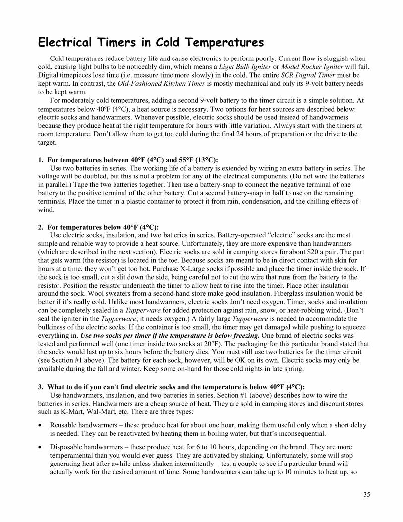
35
Electrical Timers in Cold TemperaturesCold temperatures reduce battery life and cause electronics to perform poorly. Current flow is sluggish when
cold, causing light bulbs to be noticeably dim, which means a Light Bulb Igniter or Model Rocker Igniter will fail.Digital timepieces lose time (i.e. measure time more slowly) in the cold. The entire SCR Digital Timer must bekept warm. In contrast, the Old-Fashioned Kitchen Timer is mostly mechanical and only its 9-volt battery needsto be kept warm.
For moderately cold temperatures, adding a second 9-volt battery to the timer circuit is a simple solution. Attemperatures below 40ºF (4°C), a heat source is necessary. Two options for heat sources are described below:electric socks and handwarmers. Whenever possible, electric socks should be used instead of handwarmersbecause they produce heat at the right temperature for hours with little variation. Always start with the timers atroom temperature. Don’t allow them to get too cold during the final 24 hours of preparation or the drive to thetarget.
1. For temperatures between 40°F (4°°°°C) and 55°F (13°°°°C):Use two batteries in series. The working life of a battery is extended by wiring an extra battery in series. The
voltage will be doubled, but this is not a problem for any of the electrical components. (Do not wire the batteriesin parallel.) Tape the two batteries together. Then use a battery-snap to connect the negative terminal of onebattery to the positive terminal of the other battery. Cut a second battery-snap in half to use on the remainingterminals. Place the timer in a plastic container to protect it from rain, condensation, and the chilling effects ofwind.
2. For temperatures below 40°F (4°°°°C):Use electric socks, insulation, and two batteries in series. Battery-operated “electric” socks are the most
simple and reliable way to provide a heat source. Unfortunately, they are more expensive than handwarmers(which are described in the next section). Electric socks are sold in camping stores for about $20 a pair. The partthat gets warm (the resistor) is located in the toe. Because socks are meant to be in direct contact with skin forhours at a time, they won’t get too hot. Purchase X-Large socks if possible and place the timer inside the sock. Ifthe sock is too small, cut a slit down the side, being careful not to cut the wire that runs from the battery to theresistor. Position the resistor underneath the timer to allow heat to rise into the timer. Place other insulationaround the sock. Wool sweaters from a second-hand store make good insulation. Fiberglass insulation would bebetter if it’s really cold. Unlike most handwarmers, electric socks don’t need oxygen. Timer, socks and insulationcan be completely sealed in a Tupperware for added protection against rain, snow, or heat-robbing wind. (Don’tseal the igniter in the Tupperware; it needs oxygen.) A fairly large Tupperware is needed to accommodate thebulkiness of the electric socks. If the container is too small, the timer may get damaged while pushing to squeezeeverything in. Use two socks per timer if the temperature is below freezing. One brand of electric socks wastested and performed well (one timer inside two socks at 20°F). The packaging for this particular brand stated thatthe socks would last up to six hours before the battery dies. You must still use two batteries for the timer circuit(see Section #1 above). The battery for each sock, however, will be OK on its own. Electric socks may only beavailable during the fall and winter. Keep some on-hand for those cold nights in late spring.
3. What to do if you can’t find electric socks and the temperature is below 40°°°°F (4°°°°C):Use handwarmers, insulation, and two batteries in series. Section #1 (above) describes how to wire the
batteries in series. Handwarmers are a cheap source of heat. They are sold in camping stores and discount storessuch as K-Mart, Wal-Mart, etc. There are three types:
• Reusable handwarmers – these produce heat for about one hour, making them useful only when a short delayis needed. They can be reactivated by heating them in boiling water, but that’s inconsequential.
• Disposable handwarmers – these produce heat for 6 to 10 hours, depending on the brand. They are moretemperamental than you would ever guess. They are activated by shaking. Unfortunately, some will stopgenerating heat after awhile unless shaken intermittently – test a couple to see if a particular brand willactually work for the desired amount of time. Some handwarmers can take up to 10 minutes to heat up, so
36
begin shaking them a few minutes before deploying. Never rely on a single disposable handwarmer, as thereis an occasional dud.
• Burnable handwarmers – also called “solid fuel” handwarmers – these contain a chemical stick that is set onfire and then burns inside a special case. They take slightly more time to deploy than the other types.
These last two types of handwarmers produce heat long enough that they can be activated before reaching thetarget. When using the SCR Digital Timer, you could choose to set the timer, wrap it in insulation and activate thehandwarmer prior to actually arriving at the target. Once you get there, just place the bundle in the right locationand connect it to the igniter. (In contrast, the Old-Fashioned Kitchen Timer cannot be set ahead of time becausethe wires on the face of the timer are too easily bumped.)
Handwarmers can reach temperatures in excess of 160°F (71°C), which is too hot for electronics andbatteries. The temperature listed on the package is an average and is not reliable. Don’t place handwarmersdirectly against the batteries or the timer. Place a layer of insulation between the handwarmers and the timer. Thenwrap everything in more insulation. Or make a small insulated box containing the handwarmers and the timer,separated by air space. As previously mentioned, wool sweaters from a second-hand store make good insulation.Fiberglass insulation would be better if it’s really cold. Placing handwarmers underneath the timer increases theheat delivered to the timer; placing them to the side of the timer reduces the heat.
Perform tests by placing handwarmers in a small, sealed container to determine if a particular brand will fail ifdeprived of oxygen. Most won’t, but check anyway. Test the setup at the expected temperature (either outside orin the freezer). For maximum reliability, use an indoor/outdoor thermometer with remote sensor during testing todetermine if the timer is too hot or too cold. A thermometer that automatically records minimum and maximumtemperatures will simplify the task. This may seem like a lot of work, but if you are risking years behind bars,don’t let your action get foiled because the cold weakened your batteries (or overzealous handwarmers friedthem).
Keeping the Igniter Dry:The igniter will fail if the matches get damp from rain or fog or dew. Use a large Ziploc freezer bag for
protection. It doesn’t have to be the Ziploc brand; other brands of re-closeable bags will work just as well. Get“freezer” bags because they are thicker and more tear-resistant than regular bags. Place the igniter inside the bag,squish out the air and close the seal. (The ends of the wires need to stick out.) Add electrical tape to strengthen theseal, but don’t go overboard. Roll the excess bag around the igniter, then wrap electrical tape around the outsideof the bag to keep it tightly rolled up. When the igniter bursts into flame, it will instantly melt through the thinplastic of the Ziploc.
We also tested a condom and a balloon for their ability to keep the igniter dry. Both failed. The condom wasrolled over top the matchbooks and down the flare, which was rather interesting in both a visual and a tactilesense. It seemed like the condom-wrapped igniter was going to work and we set it aside. To our surprise, thecondom ripped several minutes later, exposing all the match heads. An even more startling phenomenon occurredwith the balloon. The igniter was squeezed inside the mouth of the balloon and then the mouth was taped shut.When the igniter ignited, it made a small bang and jumped half a foot, falling off the lid of a 5-gallon bucket. Thethick, elastic rubber of the balloon captured the gases from the burning matches and flare. After a split second,enough gases had accumulated to rupture the balloon and make it jump in one direction as the gases escaped inthe other direction. Both experiments had unexpected results, which clearly illustrates the importance of testing.

37
Where to Get StartedMany of us already have firsthand experience with starting fires in wood burning stoves, fireplaces and
campfires. The principles of fire are not mere abstractions; almost everyone has observed them in operation. Onthe other hand, timers and igniters will remain abstract book knowledge until you transform the writteninstructions, step by step, into an actual device. So go purchase the materials today and start building yourself atimer. Start out first with the Old-Fashioned Kitchen Timer before working on the more versatile but complicatedSCR Digital Timer.
Some precautions are necessary. Possession of an incendiary device, even for educational purposes, can getyou into hot water with the authorities. Don’t tell anyone about your science experiment and make sure yourwork area is completely private. Don’t keep materials or completed devices around for longer than necessary.
It will be tempting to read this entire manual and then immediately turn your attention away to somethingelse. Possibly you will busy yourself reading movement newsletters that report on actions carried out by someoneelse. Maybe you will tell yourself that you‘ll learn how to build a timer later when you find a target that reallyneeds to be burned. That’s like saying you’ll learn how to build a campfire later when you are cold and wet andreally need one. Now is the time to learn. You had enough time to read this manual, so you must have enoughtime to go to the store and pick up the few materials needed. Do it after you finish reading this page.
After constructing your first timer, you’ll feel the playing field shift in your favor – even the largest earth-destroying, animal-abusing corporations are now vulnerable.