an automatic portrait system based on and-or graph representation
TRANSCRIPT

An Automatic Portrait System Based onAnd-Or Graph Representation
Feng Min1,4, Jin-Li Suo2,4, Song-Chun Zhu3,4 and Nong Sang1
1IPRAI, Huazhong University of Science and Technology, China.2Graduate University of Chinese Academy of Sciences, China.
3Departments of Statistics and Computer Science, University of California.4Lotus Hill Institute for Computer Vision and Information Science, China.
[email protected], [email protected], [email protected], [email protected]
Abstract. In this paper, we present an automatic human portrait sys-tem based on the And-Or graph representation. The system can auto-matically generate a set of life-like portraits in different styles from afrontal face image. The system includes three subsystems, each of whichmodels hair, face and collar respectively. The face subsystem can be fur-ther decomposed into face components: eyebrows, eyes, nose, mouth, andface contour. Each component has a number of distinct sub-templatesas a leaf-node in the And-Or graph for portrait. The And-Or graph forportrait is like a ”mother template” which produces a large set of validportrait configurations, which is a ”composite templates” made of a setof sub-templates. Our approach has three novel aspects:(1) we presentan And-Or graph for portrait that explains the hierarchical structure andvariability of portrait and apply it into practice; (2) we combine hair,face and collar into a system that solves a practical problem; (3) Thesystem can simultaneously generate a set of impressive portraits in dif-ferent styles. Experimental results demonstrate the effectiveness and life-likeness of our approach.
Key words: And-Or Graph, Non-Photorealistic Rendering, Face
1 Introduction
A portrait is a concise yet expressive representation of each person. A life-likeportrait should not only resemble the appearance of an individual, but alsocapture the spirit of an individual.
It is a difficult and challenging task to automatically generate a life-like por-trait from a given face image. There have been a few attempts to interactivelyor automatically generate a stylistic facial sketch by observing images drawn byartists. For example, a few template-based facial caricature systems were devel-oped by Koshimizu et al [1] and Li et al[2], which simply linked face featurepoints using image processing methods and produced stiff sketches. A numberof example-based approaches have been proposed for sketch. For instance, Li-brande[3] developed an example-based character drawing system. Freeman et

2 Lecture Notes in Computer Science: Authors’ Instructions
al[4] presented an example-based system for translating a sketch into differentstyles. With the development in texture synthesis[5] and face hallucination[6],Chen et al [7, 8] developed an example-based face sketch generation system.They used inhomogeneous non-parametric sampling to capture the statisticallikelihood between the sketch and original image, and fit a flexible template togenerate the sketch. However, this method is the mapping from image to sketch,it is difficult to change the style of portrait.
Inspired by recent development in generative model[16, 9], Xu et al [10] pre-sented a high resolution grammatical model for face representation and sketch-ing. They adopted three-layer generative model and coarse-to-fine computationto generate fine face sketches. Chen et al [11, 12] presented a generative modelof human hair for hair sketching and composite templates for cloth modelingand sketching. These models can generate vivid sketches of hair, face and cloth,however, no one combines these separate parts into one portrait system.
In this paper, we present an automatic portrait system based on the And-Orgraph representation. We build an And-Or graph for portrait which can accountfor the variability of portraits by separating the structure and style of portrait.Additionally, we build a set of sketch dictionaries for portrait components indifferent styles. With the And-Or graph for portrait and sketch dictionaries, wecan automatically generate a set of life-like portraits in different styles from agiven face image as shown in Figure 10, 11.
The rest of this paper is organized as follows. We introduce the And-Or graphfor portrait in Section 2. The automatic portrait system is presented in Section3. Experimental results are shown in Section 4. In Section 5, we will discuss thelimitations of our approach and the future work.
AND
AND
Fig. 1. Decompose portrait into components.

Lecture Notes in Computer Science: Authors’ Instructions 3
Fig. 2. The variability of portrait components.
2 The And-Or Graph for Portrait
As is shown in Figure 1, a portrait includes three parts: hair sketch, face sketch,and collar sketch. The face sketch can be further decomposed into eyebrowssketch, eyes sketch, nose sketch, and mouth sketch. All of these componentsform a rather fixed spatial configuration within the face contour. At the sametime, variability still exists in portraits, not only globally such as different viewsor posture, but also locally such as open/closed mouth or different types of hair.For example, Figure 2 shows various hair, collar, eyebrows, eyes, nose, mouth,and face contour together with their corresponding sketches.

4 Lecture Notes in Computer Science: Authors’ Instructions
We need to take three categories of variability into account. (1) Topologicalconfiguration, such as V/T collar; (2) Geometric deformation, such as thick/thineyebrows; (3) Photometric variabilities, such as light/dark hairs. In order toaccount for these variabilities, we propose an And-Or graph for portrait.
And-nodeOr-nodeLeaf node
portrait
hair face collar
face1 faceN
eye nose moutheyebrow
hair1 hairN collarNcollar1
eyebrow1 eyebrowN eye1 eyeN nose1 noseN mouth1 mouthN
facecontour
facecontourN
facecontour1
Fig. 3. The And-Or graph for portrait.
As is shown in Figure 3, each terminal(leaf) node represents a component orsub-template. Different sub-templates in the same category are represented bydistinct subgraphs. The non-terminal nodes are either And-nodes whose childrenmust be chosen jointly or Or-nodes of which only one child can be selected. AnAnd-node is an instance of the semantic meaning, which expands the regularizedconfigurations. An Or-node only has the syntax meaning, which is a switchbetween alternative sub-configurations. So the And-nodes, the Or-nodes, andthe leaf nodes constitute an And-Or graph. The And-Or graph has horizontaldash lines to specify the spatial relations and constrains among the nodes. Forexample, hair is above the face, while collar is below the face. Eyebrows, eyes,nose, mouth are within the face contour. These relations and constrains helpto link the components together to form a valid representation. Thus the And-Or graph is like a ”mother template” which produces a set of valid portraitconfigurations -”composite templates” that are made of a set of sub-templates.
As a matter of fact, an And-Or Graph is a context sensitive grammar [13],which can be regarded as a 5-tuple
Gand−or =< N = U ∪ V, T, Σ, R,A > (1)
Each element is explained as below:

Lecture Notes in Computer Science: Authors’ Instructions 5
1. Non-terminal nodes N = U ∪ V includes a set of And-nodes and Or-nodes.
U = {u1, ..., un}; V = {v1, ..., vn} (2)
An And-node u ∈ U represents a composite template, which is composed ofa set of sub-templates. An Or-node v ∈ V is a switch pointing to a set ofalternative sub-templates.
2. Terminal nodes T is a set of atomic templates.
T = {t1, ..., tn} (3)
A terminal node t ∈ T represents an object component, which can’t befurther expanded or decomposed.
3. Configurations Σ is a finite set of valid composite templates.
Σ = {G1, ..., Gn} (4)
Each graph G ∈ Σ is a specific configuration for portrait. Σ includes all ofthe possible valid configurations.
4. Relations R is a set of relations between any two nodes in the And-Or graph.
R = {r(ni,nj) =< ni, nj >; ni, nj ∈ N ∪ T} (5)
Each relation represents the statistical constraint on the attributes of thenodes.
5. Attributes A is a set of attributes for each node in the And-Or graph. For theterminal nodes ti ∈ T , A is a set of photometric and geometric transforms.
A = {(Apho(ti)
, Ageo(ti)
); i = 1, 2, ..., n} (6)
3 The Automatic Portrait System
In order to automatically generate a set of life-like portraits in different styles,we need a large number of sub-templates in different styles as the terminal nodes.We asked artists to draw the portrait in different styles on top of the originalimage with a different layer in PhotoShop. Then we manually decompose theportrait into a set of components as is shown in Figure 1. By collecting thesecomponents, we build a large database for hair, collar, eyebrows, eyes, nose,mouth, face contour and their corresponding sketches in different styles. Fromthis large database, we can extract different types of hair, face components, andcollars to build a set of sketch dictionaries in different styles. It is also convenientto change the style of portrait by changing the sketch dictionaries.
Based on the And-Or graph for portrait, we divide the portrait system intothree subsystems: hair subsystem, face subsystem and collar subsystem. The facesubsystem is the key part which can be further decomposed into face components:eyebrows, eyes, nose, mouth, and face contour. We detect face rectangle usinga boosted cascade of features[14]. Then we adopt a local Active Appearance

6 Lecture Notes in Computer Science: Authors’ Instructions
Model (AAM) [15–17] for each face component. The hair subsystem and thecollar subsystem are connected to the face subsystem. We first find the haircontour and the collar contour by the spatial relationships. Then we use shapematching to find the best matched shape with shape contexts [18]. Last we warpthe best matching shape to the corresponding shape contour by the Thin PlateSpline(TPS) [19, 20] model. The details of the three subsystems will be presentedin the following sections.
1
3
4
5
2
Fig. 4. The different types of facial components extracted from the database.
3.1 Face Subsystem
Because of the diversity in the database, we categorize the face components intofour types of eyebrows, five types of eyes, five types of nose, four types of mouth,and two types of face contour shown in Figure 4. Each type of component has itsown AAM. The AAM representation includes a set of principle components forthe geometric deformations and a set of principle components for the photometricvariabilities after aligning the landmarks. Therefore we build a dictionary for all(4+5+5+4+2=20) components and their corresponding sketches.
∆cpI = {Icp,i
geo , Icp,ipho , i = 1, 2, ..., 20} (7)
∆cpS = {Scp
i , i = 1, 2, ..., 20} (8)
where Icp,igeo and Icp,i
pho respectively denote the geometric and photometric modelsof AAM for component i. Scp
i denotes the sketch of component i.The 20 component models are learned in a supervised manner from the
database. The selection of the model for each component is controlled by five

Lecture Notes in Computer Science: Authors’ Instructions 7
switch variables lj ∈ {1, 2, .., 20}, j = 1, 2, ..., 5. Because of the symmetry of thetwo eyes and eyebrows, there are only five variables l1, l2, l3, l4, l5 which respec-tively denoted eyebrows, eyes, nose, mouth, and face contour. The inference ofthe face sketch can be represented as:
p(Scp|I;∆cpS ,∆cp
I ) =5∏
j=1
p(lj) ·5∏
j=1
p(Scplj|I; ∆cp
S ,∆cpI ) (9)
The inference of switch variables lj is done through a exhaustive way. Wefirstly pick node j as a candidate from the AAM. Then we obtain the residuebetween the synthesized image and the target image until the local model con-verges. After all the candidates are tried, the one with the least residue is chosenand its label assigned to lj . The exhaustive search can only guarantee the localoptimum. However, we argue that the result shall approximate the global opti-mal in most circumstances with the good initialization assumed. The argumentis supported by our experiment results.
Fig. 5. Render the sketch of eyebrows through its corresponding sketch.
Fig. 6. The flow chart of face subsystem.
Once we have determined the switch variables lj for each component, wecan render the sketch of each component through its corresponding sketch Scp
lj.
Taking eyebrows as an example shown in Figure 5, we can extract the accurate

8 Lecture Notes in Computer Science: Authors’ Instructions
shape and associated texture information using the best fitting AAM from anew eyebrow. Then we define the same triangular mesh over the landmarks andwarp each triangle separately from source to destination to get the vivid sketchof eyebrow.
The flow chart of face subsystem is shown in Figure 6. Firstly, we infer switchvariables lj through a exhaustive way. Secondly, we extract the accurate shapeusing the AAM for component lj and connect landmarks. Finally, we render thesketch of each component through its corresponding sketch Scp
lj.
Fig. 7. The different types of collars extracted from the database.
3.2 Hair and Collar Subsystem
There are various types of collar and hair. we select some simple and typical typesof collar and hair as templates from the database as is shown in Figure 7, 8. Weuse ∆h
S and ∆cS to represent the various sketch of hair and collar respectively.
Hair and collar cannot be handled in the same way as the face due to tworeasons. (1) Because they have many styles and are not structured in the sameregular way as the faces, building a model is not feasible. (2) There is no clearcorrespondence between source shape contours and destination shape contours.Without a correspondence, the triangular warp is not valid. Therefore, we adoptthe method of shape contexts[18] to solve these problems. Shape contexts canmeasure similarity between shapes and find the correspondence between two sim-ilar shapes. Shapes are represented by a set of points sampled from the shapecontours. In fact, the shape context is a descriptor for a reference point thatcaptures the distribution of the remaining points with respect to the reference.As the corresponding points on similar shapes will have similar shape contexts,

Lecture Notes in Computer Science: Authors’ Instructions 9
Fig. 8. The different types of hairs in two styles extracted from the database.
we can find the correspondence between two similar shapes by solving an opti-mal assignment problem. To measure similarity between shapes, shape contextdistance is defined as the symmetric sum of shape context matching costs overbest matching points
In order to choose the closest template using shape contexts, we should findthe shape contour of hair and collar from a given image first. We can find theoverall face region by skin detection. To reduce the influence of luminance onskin color, we transform the given image from RGB space to YCbCr space andonly use Cb and Cr to detect skin. Because we have found face rectangle in facesubsystem, we can get the approximate mean of skin color by calculating themean Cb and Cr in the region of face rectangle. Using the skin color, we canquickly and effectively detect the the overall face region. If the background ofthe given image is clear and static, we can easily segment out the backgroundby color detection. If the background is complex, we can use graph cuts [21,

10 Lecture Notes in Computer Science: Authors’ Instructions
TPS
TPS
Fig. 9. The flow chart of the hair and collar subsystem.
22] to segment out the background. Therefore, we can obtain the region of hairand collar after we segment out the overall face region and background from thegiven image.
Searching the closest template is the process of shape matching. More for-mally, D(p, q) denotes shape context distance between shapes p and q, P ={p1, ..., pn} denotes a set of templates, P ∗ denotes the closest template for agiven shape Q, thus
P ∗ = arg minpk∈P
D(pk, Q) (10)
The flow chart of hair and collar subsystem is shown in Figure 9. We firstlyobtain the shape contour of hair and collar by segmenting out the backgroundand face. Then we get a set of points sampled from the shape contour of hairand collar and find the closest template by minimizing the shape context dis-tance. Finally, we use a regularized TPS to map the closest template onto thecorresponding shape contour.
3.3 Multiple Style Rendering
For each portrait component, we always have a corresponding graph representa-tion shown in Figure 4, Figure 7 and Figure 8. We call them the sketch dictio-naries
∆S = {∆hS ,∆cp
S ,∆cS} (11)
The ∆S represents a special style. The inference of portrait can be representedas:
Lecture Notes in Computer Science: Authors’ Instructions 11
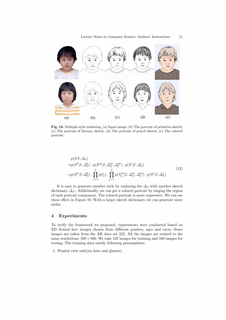
(a) (b) (c) (d) (e)
Fig. 10. Multiple style rendering. (a) Input image; (b) The portrait of primitive sketch;(c) The portrait of literary sketch; (d) The portrait of pencil sketch; (e) The coloredportrait.
p(S|I;∆S)
=p(Sh|I;∆hS) · p(Scp|I;∆cp
S ,∆cpI ) · p(Sc|I; ∆c
S)
=p(Sh|I;∆hS) ·
5∏
j=1
p(lj) ·5∏
j=1
p(Scplj|I; ∆cp
S ,∆cpI ) · p(Sc|I;∆c
S)
(12)
It is easy to generate another style by replacing the ∆S with another sketchdictionary ∆S′ . Additionally, we can get a colored portrait by tinging the regionof each portrait component. The colored portrait is more expressive. We can seethese effect in Figure 10. With a larger sketch dictionary, we can generate morestyles.
4 Experiments
To verify the framework we proposed, experiments were conducted based on225 frontal face images chosen from different genders, ages and races. Someimages are taken from the AR data set [23]. All the images are resized to thesame resolutions: 500× 500. We take 125 images for training and 100 images fortesting. The training data satisfy following prerequisites:
1. Frontal view only(no hats and glasses).
12 Lecture Notes in Computer Science: Authors’ Instructions
2. Plain style, no exaggeration.3. Each pair of image and portrait matches perfectly.4. One image corresponds a set of portraits in different styles.
Figure 11 shows some results generated by our approach. It takes about 5seconds on a Pentium IV 2.93 GHZ PC to generate a 500 × 500 portrait. Weconclude that our approach is convenient to change the style of portrait and hasgood expansibility.
5 Discussion and Conclusions
We have presented an approach to automatically generating a set of life-like por-traits in different styles. The And-Or graph for portrait is employed to accountfor the variability of portraits and separate the structure and style of the por-traits. Our approach benefits from large sketch dictionaries in different styles. Byreplacing the sketch dictionaries, it is convenient to change the style of portrait.However our approach is not able to handle the old people because the wrinklesare not taken into account.
Our approach is aimed at a number of applications, such as low bit por-trait communication in wireless platforms, cartoon sketch and canvas in non-photorealistic rendering, portrait editing and make-up on the Internet. In futurework, we will add richer features including wrinkles, mustache, and lighting vari-abilities. We’d also like to extend our approach to cartoon sketch, side face andmotion.
Acknowledgement
This work is done when the author is at the Lotus Hill Research Institute. Theauthor thanks ZiJian Xu for extensive discussions. The project is supported bythe National Natural Science Foundation of China under Contract 60672162.
References
1. H. Koshimizu, M. Tominaga, T. Fufiwara, and K. Murakami, ”On kansei facialprocessing for computerized facial caricatruing system picasso”, IEEE InternationalConferece on Systems, Man and Cybernetics, 6:294-299, 1999.
2. Y. Li and H. Kobatake, ”Extraction of facial sketch based on morphological pro-cessing”, In IEEE international conference on image processing, 3:316-319, 1997.
3. S. E. Librande, ”Example-based character drawing”, Masters thesis, Cambridge.MA, MIT, 1992.
4. W. T. Freeman, J. B. Tenenbaum, and E. Pasztor, ”An example-based approach tostyle translation for line drawings”, Technical Report 11, MERL Technical Report,Cambridge, MA, 1999.
5. A. A. Efros and T. K. Leung, ”Texture synthesis by nonparametric sampling”,Seventh International Conference on Computer Version, 1999.

Lecture Notes in Computer Science: Authors’ Instructions 13
6. S. Baker and T. Kanade, ”Hallucinating faces”, AFGR00, 2000.7. H. Chen, Y. Q. Xu, H. Y. Shum, S. C. Zhu, and N. N. Zheng, ”Example-based facial
sketch generation with non-parametric sampling”, ICCV, 2:433-438, 2001.8. H. Chen, Z. Q. Liu and et al ”Example-based composite sketching of human por-
traits”, NPAR, 95-102, 2004.9. M. J. Jones and T. Poggio, ”Multi-dimensional morphable models: a framework for
representing and matching object classes”, IJCV, 2(29):107-131, 1998.10. Z. J. Xu, H. Chen and S. C. Zhu, ”A high resolution grammatical model for face
representation and sketching”, CVPR, 2:470-477, 2005.11. H. Chen and S. C. Zhu, ”A generative model of human hair for hair sketching”,
CVPR, 2:74-81, 2005.12. H. Chen and S. C. Zhu, ”Composite templates for cloth modeling and sketching”,
CVPR, 1:943-950, 2006.13. J. Rekers and A. Schurr, ”A parsing algorithm for context sensitive graph gram-
mars”, TR-95-05, Leiden Univ, 1995.14. P. Viola and M. Jones, ”Rapid object detection using a boosted cascade of simple
features”, CVPR, 2001.15. T. F. Cootes, C. J. Taylor, D. Cooper, and J. Graham, ”Active shape models-their
training and application”, Computer Vison and Image Understanding, 61(1):38-59,1995.
16. T. F. Cootes, G. J. Edwards and C. J. Taylor, ”Active appearance models”, pro-ceedings of ECCV, 1998.
17. R. H. Davies, T. F. Cootes, C. Twining and C. J. Taylor, ”An Information theoreticapproach to statistical shape modelling”, Proc. British Machine Vision Conference,pp.3-11, 2001.
18. S. Belongie, J. Malik, J. Puzicha, ”Shape matching and object recognition usingshape contexts”, PAMI, 24(4):509-522, 2002.
19. J. Meinguet, ”Multivariate interpolation at arbitrary points made simple”, J. Ap-plied Math. Physics(ZAMP), 5:439-468, 1979.
20. H. Chui and A. Rangarajan, ”A new algorithm for non-rigid point matching”,CVPR, 2000.
21. Y. Boykov, O. Veksler and R. Zabih, ”Faster approximate energy minimization viagraph cuts”, PAMI, 23(11):1222-1239, 2001.
22. Y. Boykov and V. Kolmogorov, ”An Experimental Comparison of Min-Cut/Max-Flow Algorithms for Energy Minimization in Computer Vision”, PAMI, 26(9):1124-1137, 2004.
23. A. Martinez and R. Benavente, ”The ar face database”, Technical Report 24, CVC,1998.

14 Lecture Notes in Computer Science: Authors’ Instructions
(a) (b) (c) (d) (e)
Fig. 11. More results generated by our approach. (a) Input image; (b) The portrait ofprimitive sketch; (c) The portrait of literary sketch; (d) The portrait of pencil sketch;(e) The colored portrait.