an automated teflon microfluidic peptide synthesizer
TRANSCRIPT
Cite this: Lab Chip, 2013, 13, 3347
Received 22nd May 2013,Accepted 24th June 2013
An automated Teflon microfluidic peptide synthesizer3
DOI: 10.1039/c3lc50632k
www.rsc.org/loc
Hui Zheng,{a Weizhi Wang,{a Xiaojun Li,a Zihua Wang,a Leroy Hood,c
Christopher Lausted*c and Zhiyuan Hu*abc
We present a microfluidic synthesizer made entirely of Teflon
material for solid phase peptide synthesis (SPPS). Solvent-resistant
perfluoroalkoxy (PFA) was used to construct chip-sized devices
featuring multiple tri-layer pneumatic microvalves. Using these
devices, model peptides were automatically synthesized and
cleaved in situ in a continuous-flow manner. The total coupling
and cleavage time was significantly reduced compared to
conventional bulk reactors. The synthesis of a decapeptide, for
instance, took less than 6 h using our device while it usually takes
more than three days using conventional reactors.
Conventional biomolecule synthesizers are often geared towardsmillimolar scale assembly which is uneconomical for manybiochemical and biophysical studies in which only small amountsof material are required. Microfluidic reactors for biomoleculesynthesis have many advantages over conventional bulk reactors.1
Benefiting from the minimization of the reaction scale andenlargement of the specific surface area, the microfluidic chemicalreactions result in better yields, selectivity, safety and efficiency.2–5
For instance, microreactors that allow very small scale peptideassemblies to provide enough quantities for preliminary assays orproteomic verification can significantly save time and costs. Tomeet these requests, several microfluidic reactors of silicon orglass have been designed for specific chemical syntheses, such asthose of peptides and DNA.6–8 However, these hard materials oftenlimit the designs because the controllable microelements aredifficult to fabricate and integrate. For example, controllableelastomeric microvalves can be made very small and very reliable,but they are difficult to integrate with hard materials. On the other
hand, the popular soft polydimethylsiloxane (PDMS) microfluidicdevices suffer from poor solvent resistance even with surfacemodifications.9–11 The ideal microfluidic reactor should have boththe controllable elastomeric microvalves and the chemicalcompatibility. Fluorinated polymers are ideal materials forsolvent-resistant microreactors because of their excellent chemicalinertness. Solvent-resistant microfluidic devices for DNA synthesishave been made with photocurable perfluoropolyethers (PFPEs) byQuake et al.12,13 However, because PFPEs are commerciallyunavailable and devices can only be fabricated in a clean roomwith specialized equipment, this protocol has not been widelyused. Another fluorinated plastic named DyneonTM THV has beenapplied in microreactors. This co-polymer is not fully-fluorinated,and is only partly solvent-resistant.14 Teflon1 is a popular class offully-fluorinated polymers with excellent chemical compatibilityand suitable mechanical properties for use in microfluidics.Although patterning and bonding methods have been developed15
and thin-film multi-layer Teflon chips have been used inpetrochemical applications,16 no whole Teflon biomoleculemicrosynthesizer has previously been reported.
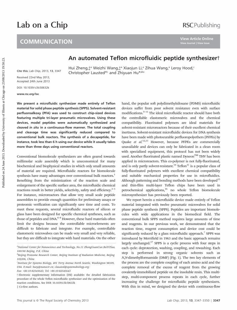
We report herein a microfluidic device made entirely of Teflonmaterial integrated with twelve pneumatic microvalves for solidphase peptide synthesis (SPPS). Peptides are important biomole-cules with wide applications in the biomedical field. Theconventional bulk SPPS method requires large amounts of timeand reagents. In our previous work, we demonstrated that thereaction time, reagent consumption and device cost could besignificantly reduced by a glass microfluidic approach.7 SPPS wasintroduced by Merrifield in 1963 and the basic approach remainslargely unchanged.17 SPPS is a cyclic process with four steps ineach cycle: deprotection, washing, coupling, and rewashing. Eachstep is performed in strong organic solvents such asN,N-dimethylformamide (DMF) (Fig. 1). The two key elements ofthe process are the complete coupling of each amino acid and thecomplete removal of the excess of reagent from the growingcovalently-immobilized peptide on the insoluble resin. This multi-step, multi-component process repeats in each cycle, furtherincreasing the challenge for microfluidic peptide synthesizers.With this in mind, we designed the device with continuous-flow
aNational Center for Nanoscience and Technology, No.11 ZhongGuanCun BeiYiTiao,
100190 Beijing, P.R. ChinabBeijing Proteome Research Center, Beijing Institute of Radiation Medicine, Beijing
102206, ChinacInstitute for Systems Biology, 401 Terry Avenue North Seattle, Washington 98109,
USA. E-mail: [email protected]; [email protected];
Fax: +86-10-82545643; Tel: +86-10-82545643
3 Electronic supplementary information (ESI) available: the detailed fabricationprocedure of the whole Teflon microfluidic synthesizer and the optimization of thereaction conditions. See DOI: 10.1039/c3lc50632k{ Co-first authors.
Lab on a Chip
COMMUNICATION
This journal is � The Royal Society of Chemistry 2013 Lab Chip, 2013, 13, 3347–3350 | 3347
Publ
ishe
d on
24
June
201
3. D
ownl
oade
d by
Uni
vers
ity o
f Il
linoi
s at
Chi
cago
on
23/0
8/20
13 1
9:50
:23.
View Article OnlineView Journal | View Issue
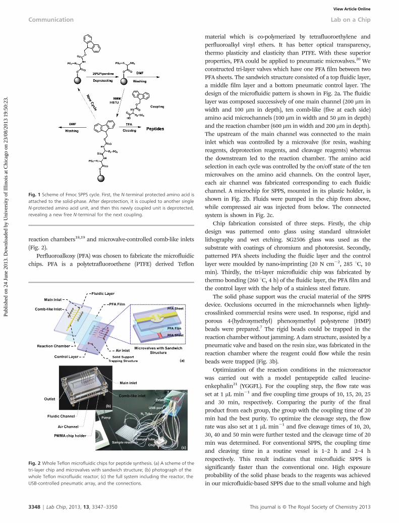
reaction chambers18,19 and microvalve-controlled comb-like inlets(Fig. 2).
Perfluoroalkoxy (PFA) was chosen to fabricate the microfluidicchips. PFA is a polytetrafluoroethene (PTFE) derived Teflon
material which is co-polymerized by tetrafluoroethylene andperfluoroalkyl vinyl ethers. It has better optical transparency,thermo plasticity and elasticity than PTFE. With these superiorproperties, PFA could be applied to pneumatic microvalves.20 Weconstructed tri-layer valves which have one PFA film between twoPFA sheets. The sandwich structure consisted of a top fluidic layer,a middle film layer and a bottom pneumatic control layer. Thedesign of the microfluidic pattern is shown in Fig. 2a. The fluidiclayer was composed successively of one main channel (200 mm inwidth and 100 mm in depth), ten comb-like (five at each side)amino acid microchannels (100 mm in width and 50 mm in depth)and the reaction chamber (600 mm in width and 200 mm in depth).The upstream of the main channel was connected to the maininlet which was controlled by a microvalve (for resin, washingreagents, deprotection reagents, and cleavage reagents) whereasthe downstream led to the reaction chamber. The amino acidselection in each cycle was controlled by the on/off state of the tenmicrovalves on the amino acid channels. On the control layer,each air channel was fabricated corresponding to each fluidicchannel. A microchip for SPPS, mounted in its plastic holder, isshown in Fig. 2b. Fluids were pumped in the chip from above,while compressed air was injected from below. The connectedsystem is shown in Fig. 2c.
Chip fabrication consisted of three steps. Firstly, the chipdesign was patterned onto glass using standard ultravioletlithography and wet etching. SG2506 glass was used as thesubstrate with coatings of chromium and photoresist. Secondly,patterned PFA sheets including the fluidic layer and the controllayer were moulded by nano-imprinting (20 N cm22, 285 uC, 10min). Thirdly, the tri-layer microfluidic chip was fabricated bythermo bonding (260 uC, 4 h) of the fluidic layer, the PFA film andthe control layer with the help of a stainless steel fixture.
The solid phase support was the crucial material of the SPPSdevice. Occlusions occurred in the microchannels when lightly-crosslinked commercial resins were used. In response, rigid andporous 4-(hydroxymethyl) phenoxymethyl polystyrene (HMP)beads were prepared.7 The rigid beads could be trapped in thereaction chamber without jamming. A dam structure, assisted by apneumatic valve and based on the resin size, was fabricated in thereaction chamber where the reagent could flow while the resinbeads were trapped (Fig. 3b).
Optimization of the reaction conditions in the microreactorwas carried out with a model pentapeptide called leucine-enkephalin21 (YGGFL). For the coupling step, the flow rate wasset at 1 mL min21 and five coupling time groups of 10, 15, 20, 25and 30 min, respectively. Comparing the purity of the finalproduct from each group, the group with the coupling time of 20min had the best purity. To optimize the cleavage step, the flowrate was also set at 1 mL min21 and five cleavage times of 10, 20,30, 40 and 50 min were further tested and the cleavage time of 20min was determined. For conventional SPPS, the coupling timeand cleaving time in a routine vessel is 1–2 h and 2–4 hrespectively. This result indicates that microfluidic SPPS issignificantly faster than the conventional one. High exposureprobability of the solid phase beads to the reagents was achievedin our microfluidic-based SPPS due to the small volume and high
Fig. 2 Whole Teflon microfluidic chips for peptide synthesis. (a) A scheme of thetri-layer chip and microvalves with sandwich structure; (b) photograph of thewhole Teflon microfluidic reactor; (c) the full system including the reactor, theUSB-controlled pneumatic array, and the connections.
Fig. 1 Scheme of Fmoc SPPS cycle. First, the N-terminal protected amino acid isattached to the solid-phase. After deprotection, it is coupled to another singleN-protected amino acid unit, and then this newly coupled unit is deprotected,revealing a new free N-terminal for the next coupling.
3348 | Lab Chip, 2013, 13, 3347–3350 This journal is � The Royal Society of Chemistry 2013
Communication Lab on a Chip
Publ
ishe
d on
24
June
201
3. D
ownl
oade
d by
Uni
vers
ity o
f Il
linoi
s at
Chi
cago
on
23/0
8/20
13 1
9:50
:23.
View Article Online

specific surface area of the microfluidic chips. In addition, thecontinuous-flow injection and rapid microvalve switching led to asufficient supply of fresh reagents, which effectively reduced masstransport limitations and reaction time. Therefore, peptidesynthetic reactions can be completed in a very short time inmicroreactors without shaking, bubbling or stirring as inconventional bulk reactors.
In addition, the on-line and continuous-flow cleavage could beeasily integrated in our device, but not in a conventional bulksynthesizer, in which an additional cleavage system is usuallyneeded. The approach of on-chip and continuous-flow cleavagecan decrease the transfer loss, reduce the exposure to corrosivereagents and shorten the whole reaction time.
To assess the performance of the microsynthesizer, a modeldecapeptide derived from the FLAG peptide22 with the sequenceGGDYKDDDDK was synthesized. During the deprotection andwashing steps, the pneumatic valve in the main channel was onand the reagent was pumped into the reaction chamber at the flowrate 1 mL min21 (deprotection) and 4 mL min21 (washing). Duringthe coupling steps, the valves of the comb-like channels wereturned on sequentially in each cycle and the amino acid reagentwas pumped into the reaction chamber at a flow rate of 1 mLmin21. When one reagent was loading, only the correspondingmicrovalve was turned on (Fig. 3c) and the target reagent wasinjected into the channel while the other valves were turned off(Fig. 3d) to prevent other reagents into the reaction chamber. Afterthe elongation of the peptide, on-line cleavage was carried outfrom the main inlet. The crude peptide was collected directly fromthe outlet.
The synthesized peptide was analysed by reversed-phase high-performance liquid chromatography (RP-HPLC) and characterizedby matrix assisted laser desorption ionization time of flight massspectrometry (MALDI-TOF-MS). The HPLC chromatograms andmass spectra are shown in Fig. 4 and the purity of the finalproducts was determined by integration of the areas under thepeaks. All the experiments were repeated three times. An averagepurity of 90.3% for the crude peptide products was obtained.Further purification by RP-HPLC was also carried out to determinethe yield of the purified peptide. An average yield of 81.0% wascalculated by substituting the peak area value into the standard
linear equation. Another model peptide (HYYYYYYYYY) withmany aromatic amino acids was synthesized. This peptide hasrepetitive hydrophobic units that qualify it as a difficult sequencein vessel peptide synthesis. It turned out that in our microfluidicsynthesis the reaction was quite efficient. As shown in Fig. S5,ESI,3the crude product has a purity of 73.7% and a yield of 69.3%even under ordinary reaction conditions. We think our micro-fluidic system can obtain purities and yields as good asconventional vessel SPPS if not better.23–25
Conclusions
We have developed a PFA microsynthesizer for automatic SPPSand demonstrated the speed and efficiency of the solvent-resistantmicrofluidic device. Such a device can provide significantly betterflexibility and automation than devices made of hard materials.With in situ continuous flow and automatic peptide cleavage, thefinal decapeptide product was obtained from the chip outletdirectly within 6 h. A parallel controlled microdevice is underdevelopment to synthesize high-throughput and small amount ofpeptides for proteomic studies. In the near future, whole Teflonmicrofluidic chips may be adapted to a range of biomoleculesynthesis, such as peptoids, nucleic acids and polysaccharides.The parallel, chip-sized automated instruments employing thehighly efficient continuous flow process will provide a rapidpreparation of biomolecules with high quality and high-through-put.
Acknowledgements
This work was supported by the Chinese Academy of Science(YZ201217), the National Natural Science Foundation of China(31270875), the International S&T Cooperation Program ofChina (2010DFB33880), the Beijing Municipal Natural ScienceFoundation (5122039) and the State Key Development Program
Fig. 4 Characterization of the on-chip synthesized decapeptide GGDYKDDDDK.(a) RP-HPLC chromatogram of on-chip synthesized GGDYKDDDDK; (b) RP-HPLCchromatogram of the GGDYKDDDDK standard sample; (c) MALDI-TOF of on-chip synthesized GGDYKDDDDK. Chromatography column: ODS-100V (3 mm)HPLC column; gradient: 0–30–35 min, 5–80–80% aqueous acetonitrilecontaining 0.1% TFA; flow rate: 1 mL min21, UV: 220 nm, AUFS: 0.01.
Fig. 3 (a) SEM images of the rigid beads; (b) trapping of the rigid beads by themicrovalve in the reaction chamber; (c) microvalve on; (d) microvalve off.
This journal is � The Royal Society of Chemistry 2013 Lab Chip, 2013, 13, 3347–3350 | 3349
Lab on a Chip Communication
Publ
ishe
d on
24
June
201
3. D
ownl
oade
d by
Uni
vers
ity o
f Il
linoi
s at
Chi
cago
on
23/0
8/20
13 1
9:50
:23.
View Article Online
for Basic Research of China grant (2011CB915502). The workwas also funded in part by the National Institute of GeneralMedical Sciences, under grant No. 2P50 GM076547/Center forSystems Biology.
References
1 K. Jahnisch, V. Hessel, H. Lowe and M. Baerns, Angew. Chem.,Int. Ed., 2004, 43, 406–446.
2 P. Watts and C. Wiles, Chem. Commun., 2007, 443–467.3 A. Lebedev, R. Miraghaie, K. Kotta, C. E. Ball, J. Zhang, M.
S. Buchsbaum, H. C. Kolb and A. Elizarov, Lab Chip, 2013, 13,136–145.
4 J. Ji, L. Nie, L. Qiao, Y. Li, L. Guo, B. Liu, P. Yang and H.H. Girault, Lab Chip, 2012, 12, 2625–2629.
5 D. F. Rivas, P. Cintas and H. J. G. E. Gardeniers, Chem.Commun., 2012, 48, 10935–10947.
6 R. C. Wootton, R. Fortt and A. J. de Mello, Lab Chip, 2002, 2,5–7.
7 W. Wang, Y. Huang, J. Liu, Y. Xie, R. Zhao, S. Xiong, G. Liu,Y. Chen and H. Ma, Lab Chip, 2011, 11, 929–935.
8 K. Jahnisch, V. Hessel, H. Lowe and M. Baerns, Angew. Chem.,Int. Ed., 2004, 43, 406–446.
9 Y. Wu, Y. Huang and H. Ma, J. Am. Chem. Soc., 2007, 129,7226–7227.
10 B. Huang, H. Wu, S. Kim and R. N. Zare, Lab Chip, 2005, 5,1005–1007.
11 K. Ren, Y. Zhao, J. Su, D. Ryan and H. Wu, Anal. Chem., 2010,82, 5965–5971.
12 J. P. Rolland, R. M. Van Dam, D. A. Schorzman, S. R. Quake andJ. M. DeSimone, J. Am. Chem. Soc., 2004, 126, 2322–2323.
13 Y. Huang, P. Castrataro, C. C. Lee and S. R. Quake, Lab Chip,2007, 7, 24–26.
14 S. Begolo, G. Colas, J. L. Viovy and L. Malaquin, Lab Chip, 2011,11, 508–512.
15 K. Ren, W. Dai, J. Zhou, J. Su and H. Wu, Proc. Natl. Acad. Sci. U.S. A., 2011, 108, 8162–8166.
16 T. W. de Haas, H. Fadaei and D. Sinton, Lab Chip, 2012, 12,4236–4239.
17 R. B. Merrifield, J. Am. Chem. Soc., 1963, 85, 2149.18 A. Dryland and R. C. Sheppard, J. Chem. Soc., Perkin Trans. 1,
1986, 125–137.19 J. D. Wade, J. Bedford, R. C. Sheppard and G. W. Tregear, Pept.
Res., 1991, 4, 194–199.20 W. H. Grover, A. M. Skelley, C. N. Liu, E. T. Lagally and R.
A. Mathies, Sens. Actuators, B, 2003, 89, 315–323.21 K. S. Lam, S. E. Salmon, E. M. Hersh, V. J. Hruby, W.
M. Kazmierski and R. J. Knapp, Nature, 1991, 354, 82–84.22 J. D. Hood, Science, 2002, 298, 364–364.23 N. A. Sole and G. Barany, J. Org. Chem., 1992, 57, 5399–5403.24 R. Subiros-Funosas, G. A. Acosta, A. El-Faham and F. Albericio,
Tetrahedron Lett., 2009, 50, 6200–6202.25 M. Kessler, R. Glatthar, B. Giese and C. G. Bochet, Org. Lett.,
2003, 5, 1179–1181.
3350 | Lab Chip, 2013, 13, 3347–3350 This journal is � The Royal Society of Chemistry 2013
Communication Lab on a Chip
Publ
ishe
d on
24
June
201
3. D
ownl
oade
d by
Uni
vers
ity o
f Il
linoi
s at
Chi
cago
on
23/0
8/20
13 1
9:50
:23.
View Article Online