an architectural proposal for future wireless emergency response networks with broadband services
TRANSCRIPT

� An Architectural Proposal for Future WirelessEmergency Response Networks withBroadband ServicesDanielle Hinton, Thierry E. Klein, and Mark Haner
Local and federal governments have recognized the importance of mobileemergency response networks that can rapidly establish reliablecommunication links to support multimedia broadband applications. In thispaper, we describe a novel proposal for a scalable and flexible architecture tosupport the needs of such future wireless emergency response networks. Wefirst describe a series of requirements and performance expectations thatfuture wireless network architectures must satisfy. These requirements thenmotivate our investigations of several key technical areas. In particular, wepropose a novel hybrid network architecture that includes a fixed andpermanently deployed part as well as a mobile/portable infrastructure that isdeployed as the capacity and connectivity needs arise. This very flexiblearchitecture dynamically manages the integration of emergency responseapplications with municipal and civic services to provide the maximumachievable performance for the latter, while at the same time ensuring thepriority and quality of service (QoS) requirements of the former. Finally, weprovide algorithms for dynamically managing both types of applications in ajoint and integrated network through flexible frequency partitioning as wellas through dynamic renegotiation of the QoS performance targets andadmission control. © 2005 Lucent Technologies Inc.
organizations. In addition, future emergency response
networks are also expected to support the day-to-day
needs of the local and regional authorities and to pro-
vide dynamic access to municipal and civic services. It
is expected that the government’s need for such sub-
stantial network support and the corresponding spec-
trum will occur relatively infrequently. In general,
there is a continuum of emergency needs between
day-to-day operations and catastrophic events. While
these catastrophic events happen very infrequently
OverviewLocal and federal governments are increasingly
aware of the importance of mobile emergency re-
sponse systems that can be deployed very rapidly in
crisis situations. From a communication perspective,
one of the main goals of such systems is the rapid and
reliable establishment of high-speed communication
links supporting broadband applications, such as
streaming video or access to databases, between the
rescue crews and their headquarters, political institu-
tions, military and police forces, and international
Bell Labs Technical Journal 10(2), 121–138 (2005) © 2005 Lucent Technologies Inc. Published by Wiley Periodicals,Inc. Published online in Wiley InterScience (www.interscience.wiley.com). • DOI: 10.1002/bltj.20097

122 Bell Labs Technical Journal
and tend to be in localized areas, they may neverthe-
less occur anywhere at any time, and appropri-
ate response networks must either be in place or be
quickly deployed. Building a network infrastruc-
ture and allocating spectrum to solely accommodate
these worst-case scenarios of wireless communication
needs, however, would require a huge investment.
The vast majority of the time, the nation is not faced
with 9/11-scale disasters; moreover, the vast majority
of the territory is not affected by such large-scale
emergencies. Building a global emergency response
network for worst-case scenarios would therefore re-
sult in tremendous waste of limited spectrum and in-
frastructure resources. Consequently, having a flexible
and scalable architecture that can support various
needs and deployment scenarios, while at the same
time providing maximum utilization and the greatest
return on investment, is crucial.
To achieve precisely this objective, we propose a
solution that not only services the public’s safety
needs, but also supports the broader wireless needs
of municipal services. This is a sector where the po-
tential gains of wireless access have long been recog-
nized, but progress has been slow, if not nonexistent,
because of the costs associated with commercial net-
works. Municipal access to the wireless spectrum in-
cludes services such as broadband access to public
schools, libraries, and government buildings; database
access; sensor and voice capabilities for maintenance
workers and health and safety inspectors; and traffic
congestion reports. According to this proposal, the
government would license a public safety band (e.g.,
the 700 MHz band) with a broad enough spectrum
to service emergencies ranging from day-to-day pub-
lic safety communications to large-sized emergencies
[12]. (For the purposes of this paper, government refers
to the local, regional, or federal authorities that fi-
nance, build, and operate the emergency networks.)
In the very high proportion of time that only a portion
of the wireless spectrum is required to satisfy the
needs of day-to-day communications and moderate-
sized emergencies, the remaining portion of the avail-
able spectrum could be allocated for municipal and
civic services. In times of heightened emergencies,
those resources could be reclaimed and allocated as
needed to support emergency personnel.
In the sections that follow, we first describe a series
of requirements and performance expectations that fu-
ture wireless network architectures must satisfy. These
requirements motivate our investigations of several key
technical areas. As a result, we propose a novel hybrid
network architecture that includes a fixed and perma-
nently deployed part as well as a mobile/portable in-
frastructure that is deployed as the capacity and
connectivity needs arise. In addition, this flexible de-
ployment architecture is instrumental in ensuring the
reliability and robustness of the network. We then de-
scribe a series of algorithms for efficiently managing
the integration of emergency response applications
with municipal and civic services to provide the maxi-
mum achievable performance for the latter, while at
the same time ensuring the priority and quality of serv-
ice (QoS) requirements of the former. These algorithms
include flexible frequency partitioning, dynamic QoS
negotiation, and admission control mechanisms. Our
investigations highlight the need for controlling and
managing the network through real-time measure-
ments of the network performance at different time
scales in order to achieve the maximum system per-
formance by real-time control, network diagnostic pro-
cedures, and network element self-organization.
Panel 1. Abbreviations, Acronyms, and Terms
AAA—Authentication, authorization, andaccounting
CDMA—Code division multiple accessEMS-services—Emergency servicesEV-DO—CDMA2000* evolution–data
optimizedEV-DV—CDMA2000 evolution–data/voiceFBS—Fixed base stationGPS—Global Positioning SystemHSDPA—High-speed downlink packet accessIP—Internet ProtocolMAC—Medium access controlMGW—Mobile gatewayMUNI–services—Municipal and civic servicesNMT—Network management toolOFDM—Orthogonal frequency division
multiplexingPBS—Portable base stationQoS—Quality of service

Bell Labs Technical Journal 123
System RequirementsWe now describe a series of requirements placed
on future emergency response networks, both from
the point of view of the applications that need to be
supported in an integrated fashion and from the de-
ployment and management perspective of these net-
works. These requirements are inspired to some extent
by the government’s vision as outlined in the require-
ments document [12] issued by the Department of
Homeland Security.
Supported ApplicationsFuture emergency response networks are ex-
pected to efficiently integrate a plethora of different
applications with different requirements and per-
formance objectives. Some of these applications entail
new technical challenges for the network infrastruc-
ture as well as for resource management. We envi-
sion that, in a fully deployed emergency response
network, the following applications need to be
supported:
• Voice call and push-to-talk applications. As essential
components of an emergency communication
network, these applications are taken as the rep-
resentatives for low-rate applications with strin-
gent delay and packet loss requirements. We
emphasize that the envisioned network is inher-
ently a packet data network, and therefore the
voice and voice-like applications must be sup-
ported over an Internet Protocol (IP) network
infrastructure.
• Access to database and interactive applications. The
prototypical applications in this category are Web
browsing and file transfer applications, which re-
quire medium transmission rates, have less strin-
gent delay requirements than voice applications,
and exhibit bursty traffic characteristics. Efficient
information retrieval and fast and reliable infor-
mation delivery are crucial for these applications,
as emergency workers may need to access data-
bases of floor plans, emergency exits, or elevator
shafts.
• Real-time video applications. These applications pro-
vide an accurate view of the emergency situation
to on-site and central coordinators and help in
directing the appropriate response measures. In
general, the network needs to support real-time
applications requiring medium to large transmis-
sion rates with stringent delay requirements. In
particular, it is envisioned that video applications
need to be supported in both downlink and up-
link channel directions. This requires new sched-
uling and resource allocation algorithms to
provide the necessary QoS guarantees and low
end-to-end delays, especially in light of the fact
that the terminals are battery operated and have
limited energy supplies. Therefore, the tradeoffs
between throughput and QoS and delay and en-
ergy efficiency have to be investigated anew.
• Environmental and vital monitoring sensors: It is
anticipated that emergency workers will be
equipped with breathing, pulse, and oxygen tank
sensors that feed back information on the health
of the emergency workers. Furthermore, emer-
gency crews and vehicles will be expected to de-
ploy temperature, humidity, and radiation sensors
to detect any abnormalities in the environment
and to aid in adjusting the emergency response
measures to the conditions at hand. Sensors typ-
ically require low bandwidth and are quite delay-
tolerant.
• Location-tracking applications. Emergency workers
and robotic vehicles are to be equipped with sen-
sors that provide accurate position and velocity
information. This can be achieved by using three-
dimensional Global Positioning System (GPS) in-
formation or, alternatively, by making use of
specialized sensors and triangulation methods re-
lying on the available network infrastructure,
such as neighboring base stations or mobile
devices.
• Broadcasting and multicasting services. The need to
broadcast common information to different re-
ceivers will be significantly increased in future
emergency networks (e.g., the entire team should
be informed of the status of the emergency situ-
ation). The need for broadcasting is not tied to a
particular application but is a general requirement
applicable to all the above-mentioned services. A
straightforward strategy would be to simply use
multiple unicast transmissions to the different
mobile terminals. However, in order to reduce the

124 Bell Labs Technical Journal
required radio resources, a more efficient and ro-
bust broadcasting and multicasting solution is
sought, in which all the receivers in the broad-
cast set can decode information from one trans-
mission sent on a dedicated broadcast channel.
The main difficulty arises from the fact that the
terminals are located in different positions and
have different and time-varying channel condi-
tions. In a conservative approach, the informa-
tion is encoded at the largest possible rate that all
the receivers can reliably decode. We envision a
more advanced solution based on multi-resolution
encoding of the common information so that all
the terminals receive the common information,
albeit at different levels of QoS, depending on
their channel conditions. For example, in a video
transmission, all the terminals may be able to de-
code the coarsely transmitted data and receive
black and white video images. However, the ter-
minals in good channel conditions may in addi-
tion be able to decode more refined information
and receive colored images. The opportunities for
multi-resolution coding are of course tied to the
flexibility of the underlying application to adapt
its content delivery to the state of the network
and the channel conditions. As an illustrative ex-
ample, we would advocate using multi-resolution
encoding for voice and video applications,
whereas robust encoding at the largest common
transmission rate would be more appropriate for
file transfers.
From the description of the desired applications, it is
quite evident that future emergency response net-
works need to support a variety of applications with
vastly different QoS requirements, including maxi-
mum delay and delay jitter constraints, minimum
throughput requirements, packet loss probability,
packet error rates, probability of dropped connections,
and accuracy of the transmitted information. In gen-
eral, these applications fall in the context of broad-
band wireless services and cannot be efficiently
supported over current third-generation wireless net-
works, at least not in a scalable fashion with the abil-
ity to support potentially hundreds of emergency
workers. In a nutshell, this proposal requires that the
infrastructure be able to provide large network-wide
throughputs of at least an order of magnitude larger
than today’s network throughputs (in excess of about
100 Mb/s/sector) and low end-to-end delays of at
least an order of magnitude smaller than today’s net-
work delays (or less than about 10 msec).
Network Infrastructure RequirementsThe requirements and expectations placed on the
network infrastructure and its deployment include:
• Rapid and scalable deployment. It is becoming in-
creasingly important to have mobile emergency
response systems that can be deployed very rap-
idly in crisis situations anywhere at any time. The
size of the network should be scalable and easily
adjustable to the level of emergency (which can
range from day-to-day rescue operations to 9/11-
scale catastrophic events).
• Reliability and redundancy. Reliability is paramount
to a successful deployment of an emergency re-
sponse network. In this paper, we are mostly con-
cerned with the reliability that ensures that all
the users and terminals always have an accept-
able connection to the backbone network. Of
course, in a practical system, reliability also in-
cludes the ability to guard against hardware and
software failures.
• Mobility and portability. The network architecture
should allow the end terminals to be mobile while
continuously maintaining the connections and
sustaining the applications. Emergency response
networks require different levels of mobility.
Mobility support at vehicular speeds is needed
when emergency crews are deployed to the emer-
gency site, during which voice, Web browsing,
and access to database applications need to be en-
abled. However, once upon the site, portability is
deemed to be sufficient as the terminals are only
expected to move within a limited area around
the emergency site, which would typically corre-
spond to the area covered by a cellular base sta-
tion. At that time, more elaborate applications
(such as video applications, sensors, and location-
based and location-tracking applications) need to
be supported.

Bell Labs Technical Journal 125
• Integration and seamless switching of technologies. The
overall network infrastructure is expected to con-
sist of different subnetworks, each being built on
potentially different platforms and technologies.
Therefore, the network should be able to integrate
the different technologies and, wherever feasible,
to consider synergies to enhance efficiency. Such
synergies could be envisioned in the areas of au-
thentication, security, and accounting by imple-
menting a single authentication, authorization,
and accounting (AAA) server capable of handling
multiple requests from the different subnetworks.
At the same time, mobile terminals should be able
to switch between different technologies in a
seamless and transparent fashion. This switch can
be ordered for different reasons, including, for ex-
ample, the level of service that can be achieved,
reduced connection capabilities due to user mo-
bility or channel fading, and QoS provisioning. In
addition, having multiple connection options is a
crucial step toward ensuring reliability and ro-
bustness in wireless networks. The additional flex-
ibility afforded by the multiple connection options
entails an increased complexity in selecting the
preferred connection at any given time. A net-
work controller, implemented in a centralized or
preferably a distributed fashion, is required to ar-
bitrate between the different options and make
the “optimal” connection decisions, both for the
benefit of the individual terminals and the overall
network as well.
Flexible and Scalable Wireless NetworkArchitecture
In order to facilitate the rapid establishment of
communication links and the efficient use of the de-
ployed infrastructure, we propose a dual approach in
which some parts of the network infrastructure are
permanently deployed and other parts are portable,
easily deployable, and upgradable if required. A high-
level view of the proposed architecture is shown in
Figure 1. It is envisioned that a high-speed, optical
backbone network is deployed throughout the geo-
graphical region of interest. This backbone network,
which forms the foundation of the network, is
connected to optical access networks. The access net-
works serve to connect all end points in a high-
bandwidth and reliable network, and they are
assumed to have multiple “entry points” to which lo-
cally deployed subnetworks can be connected.
Examples of such entry points include cellular base
stations, access points, servers, and databases. Note
that these entry points are considered as part of the
permanent structure of the network. In order to en-
sure that the wireless network can reliably meet the
needs of the public safety personnel, the government
deploys its own wired backbone and access networks.
A solution that would simply consider the emergency
personnel as another set of customers and reuse the
commercial networks would most likely encounter
overload conditions, particularly in times of emergen-
cies when both the government personnel and wire-
less service customers are expected to generate a large
amount of traffic and high call volumes. Therefore,
our solution of providing a separate network for the
emergency response system reduces the probability of
overload and makes system management easier, as
there are no conflicting objectives between the gov-
ernment and the commercial service providers.
It is most cost efficient for the government to act
essentially as a wireless service provider that deploys
its own base stations, but reuses as much as possible
the same network infrastructure as commercial service
providers. It is therefore imperative that emergency
response networks be built on standards-compliant
technologies so that economies of scale and multi-
vendor and interoperable solutions can be employed.
However, emergency response networks and com-
mercial multimedia networks most likely have differ-
ent objectives (such as connectivity and reliability
versus throughput and revenue maximization), so
that the management of the network architecture
ought to be different in both deployment scenarios.
In addition, in order to make the most efficient use
of the deployment of the wireless infrastructure and
due to the time-varying and highly fluctuating traffic
demands for emergency response networks, munici-
pal and civic services are allowed to connect to the
same base stations and dynamically share the same
radio access network as the emergency response

126 Bell Labs Technical Journal
applications. However, active services at the time of
emergencies must yield access to the higher priority
emergency applications.
The portable part of the network consists of the
mobile devices and locally deployed access points (also
called mobile gateways), as well as portable base
stations that are temporarily deployed for extra cov-
erage and capacity enhancements. The portable base
stations and the mobile gateways themselves serve as
access points for wireless terminals and route the traf-
fic to and from the neighboring fixed base stations.
The portable part of the network infrastructure there-
fore also includes broadband wireless links used for
backhauling traffic to one or more of the entry points
to the access network. We also emphasize that the
portable part of the network includes the possibilities
of peer-to-peer communication and multi-hop rout-
ing, which are viewed as integral parts in ensuring
the reliability and the robustness of the network by
providing a mobile terminal with multiple connec-
tion capabilities and routing options to the access
network. It is not required that the terminal main-
tain multiple connections in a continuous fashion,
but it is required that the terminal be able to switch to
an alternate connection if the need arises (e.g., poor
connection due to mobility or channel fading, failing
equipment on the terminal or the network side, over-
loaded network components). Provided that the ter-
minals are properly equipped and configured,
alternative routes can be established in ad hoc fashion
Fixed base station
Core network
Access network
High-speed broadbandwireless backhaul links
Portable base station
Mobilegateway
Figure 1. High-level view of proposed network architecture.
Bell Labs Technical Journal 127
as the need arises. For example, if a terminal’s direct
connection to the base station is broken, the terminal
broadcasts query messages to determine if there are
any terminals in its neighborhood that can be used
as relays. Upon reception of such a query message, a
neighbor responds with its capabilities and its will-
ingness to serve as a relay for the asking terminal, as
well as with information on its own channel condition
and the QoS that can be expected by the asking ter-
minal. If multiple connection possibilities arise, the
asking terminal uses this information to select the pre-
ferred relay. In addition, if the link between the mo-
bile gateway and a portable base station has become
unusable, the mobile gateway can directly route the
traffic to a fixed base station, albeit at a lower
throughput and at a potentially degraded QoS.
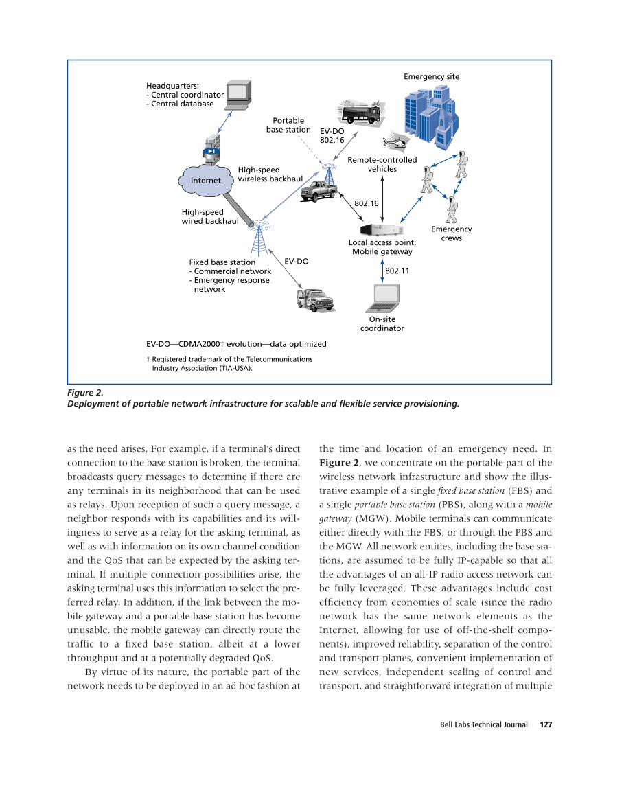
By virtue of its nature, the portable part of the
network needs to be deployed in an ad hoc fashion at
the time and location of an emergency need. In
Figure 2, we concentrate on the portable part of the
wireless network infrastructure and show the illus-
trative example of a single fixed base station (FBS) and
a single portable base station (PBS), along with a mobile
gateway (MGW). Mobile terminals can communicate
either directly with the FBS, or through the PBS and
the MGW. All network entities, including the base sta-
tions, are assumed to be fully IP-capable so that all
the advantages of an all-IP radio access network can
be fully leveraged. These advantages include cost
efficiency from economies of scale (since the radio
network has the same network elements as the
Internet, allowing for use of off-the-shelf compo-
nents), improved reliability, separation of the control
and transport planes, convenient implementation of
new services, independent scaling of control and
transport, and straightforward integration of multiple
Headquarters:- Central coordinator- Central database
Fixed base station- Commercial network- Emergency response network
Remote-controlledvehicles
On-sitecoordinator
Emergency site
EV-DO802.11
802.16
Portablebase station
High-speedwireless backhaul
High-speedwired backhaul
EV-DO—CDMA2000† evolution—data optimized
† Registered trademark of the Telecommunications Industry Association (TIA-USA).
Local access point:Mobile gateway
Emergencycrews
EV-DO802.16
Internet
Figure 2. Deployment of portable network infrastructure for scalable and flexible service provisioning.

128 Bell Labs Technical Journal
networks [6, 11, 13]. Figure 2 only shows the de-
ployment of a single portable base station, but it is
quite apparent that the portable infrastructure can
easily be scaled to include multiple portable base sta-
tions and local subnetworks as the needs arise and
change over time. One of the most important issues in
this gradual deployment of the network infrastruc-
ture is to make sure that the portable network is ap-
propriately and reliably connected to the access
network. In the remainder of this section, we provide
more details on the portable part of the network in-
frastructure, the different network entities, and their
deployment and management procedures.
Mobile GatewayWhile the government’s central network coordi-
nator manages the day-to-day traffic in the public
safety band, an MGW is deployed to provide on-site
network management for a moderate to large-scale
emergency that requires the coordination of several
crews from across the public safety sector. The MGW
is essentially a light base station that provides addi-
tional network capacity in terms of the number of
calls that can be supported and the achievable
throughput. It also serves as the anchor and the access
point for locally deployed subnetworks. In this role, it
enables the communication between emergency
crews and provides connectivity to the wide area
network. In its traditional role as a gateway, it relays
incoming calls to the appropriate terminals and
forwards outgoing calls either to an FBS or to a PBS.
In addition, local traffic between members of emer-
gency crews does not have to be routed through the
backbone network; it can instead be locally routed by
the MGW. The MGW should be fairly small, light-
weight, and durable enough to fit inside an on-site
coordinator’s backpack. It should also be able to
function and maintain its connectivity while
traveling at vehicular speeds around the scene of an
emergency.
Portable Base StationIn order to further increase the capacity of the
network, improve reliability, and further minimize
delay, a PBS is envisioned as the second emergency
response network tool to be deployed. The PBS,
which should weigh approximately 40 kg—or about
an order of magnitude less than current base
stations—and should be easily transportable on the
back of a small truck, should be powered by that
truck’s battery. Upon setup, the PBS becomes a part of
the portable network infrastructure and is connected
to an FBS by a broadband wireless backhaul link. Its
main functionalities are to provide additional network
capacity and to serve as a router between the portable
and locally deployed network and the fixed backbone
network. The deployment of a PBS can be likened to
cell splitting in traditional cellular networks, except
that its deployment is temporary and its connectivity
to the wired network has to be established in real
time. The performance and interaction of the PBS
with the neighboring FBS and other locally deployed
PBSs is optimized in real time for maximum network
performance and efficiency. Such an optimization re-
quires on-site communications and coordination be-
tween the different network elements. While the PBS
functions virtually identically to the MGW, it never-
theless offers significant capacity gains due to its larger
transmit power and greater receptivity owing to its
higher and more powerful antennae. Along with the
MGW, the PBS adds robustness to the emergency net-
work, providing multiple paths for intra-cellular rout-
ing, thereby increasing connectivity and decreasing
delay for time-critical emergency response needs.
Air Interface TechnologiesWe now briefly comment on the possible air in-
terface technologies, although this is not the main
focus of this paper. We envision that mobile terminals
can communicate directly with FBSs through existing
third-generation technologies, such as EV-DO [1],
EV-DV [2] or HSDPA [3, 10], using relatively small
bandwidths of less than 5 MHz. In addition, dual
technology devices communicate with the MGW and
the PBS through high-speed broadband wireless links
using up to 20 MHz channels, for example. As an il-
lustrative example, these links could be based on the
802.16 standard [9] or other known and future wire-
less broadband technologies. We point out that the de-
ployed technology needs to support mobility as the

Bell Labs Technical Journal 129
terminals (such as remote-controlled vehicles) may
move around the emergency site. Note, however, that
handoffs between different access points and base sta-
tions may be more limited. Therefore, one could use,
for example, 802.16e technology for links between
the mobile terminals and the MGW, the FBS, and the
PBS with a 5 to 10 MHz bandwidth. On the other
hand, 802.16d with a 20 MHz bandwidth could be
used for the wireless backhaul link between PBSs and
the FBSs. Finally, teams of emergency crews may com-
municate back and forth through short-range, local
area wireless networks, such as those using, for ex-
ample, 802.11 technology, while one of the team
members maintains a connection to the MGW. Such a
solution would limit the potential interference be-
tween different parts of the network. Nevertheless, it
is imperative that alternative connection capabilities
exist in case the local area network becomes
disconnected.
Deployment ProceduresIn this section, we turn our attention to the de-
ployment procedures and the establishment of the
communication links between the different network
entities in the architecture.
Mobile gateway deployment procedures. Upon ar-
rival to the scene of an emergency, and assuming the
MGW arrives before a PBS, the MGW runs the fol-
lowing procedure to become a functioning part of the
network (a signaling chart corresponding to this pro-
cedure is shown in [8]):
1. The MGW scans the public safety frequency band
for control channels associated with the deployed
FBSs.
2. The MGW extracts the IDs of the detected FBSs,
ranks them according to signal strength, and then
selects the highest ranked FBS. Note that other
selection criteria, such as base station loading or
QoS support, can also be considered.
3. The MGW authenticates and registers with the
selected FBS.
4. If the selected FBS is heavily loaded or cannot
handle the traffic from the MGW, it notifies the
MGW, which then traverses its rankings from
step 1 and makes contact with the new best FBS.
The procedure is repeated until an FBS is
selected as the point of contact for the MGW to
provide access to the wired network.
5. The MGW sends a message to the selected FBS
with its connection capabilities and pilot informa-
tion and requests corresponding information from
the selected FBS.
6. The selected FBS is instructed to notify the FBSs
and mobile terminals in the local neighborhood
of the presence of the MGW, including the
transmission frequency, the pilot assignment,
and the transmission capabilities of the MGW.
7. The MGW runs the dynamic network configura-
tion tool to deduce network parameters (includ-
ing, e.g., power levels, transmission frequencies,
and antenna adjustments) for the new network
topology, and sends those parameters to the FBS
with instructions for incrementally adjusting
these parameters.
8. The FBS in the network should adjust the tunable
parameters according to the procedure described
below in the “Real-Time Measurements and
Dynamic Network Optimizations” section.
9. The MGW begins running the network man-
agement tool (NMT) to determine, among other
things, the assignments of mobiles to base
stations and potential handoffs, as well as power
and rate allocations, codes and tones, transmis-
sion time slots, and QoS parameters.
10. Regular network operations resume; these
include:
a. Maintaining contact with the selected FBS via
periodic messages on the control channel.
b. Sending the selected FBS regular NMT state
updates, which should be used if the MGW
is disconnected or unable to perform the
functionalities of the NMT. In this case, the
selected FBS takes over the responsibility of
the NMT.
The NMT comprises a suite of resource allocation,
mobility management, and dynamic network con-
figuration tools that are devised to optimize the per-
formance of the network. These include power and
rate control functions, scheduling, admission control,
QoS negotiation, and handoff algorithms.

130 Bell Labs Technical Journal
If the PBS arrived first to the scene, in step 2 of
the above procedure, the MGW receives a response
from an already operational PBS running the NMT
(see the procedure below for deployment of a PBS
without the presence of an MGW). In this case, the
MGW is connected to the network through the PBS,
although this connection could be periodically reeval-
uated based on the underlying connection criterion.
However, the responsibility of running the NMT re-
mains with the PBS. Instead of steps 8 and 9 above,
the MGW now:
1. Begins collecting information on the channel
state of the mobile terminals, their power levels,
and their queue sizes and then forwards the
information to the NMT running on the PBS.
2. Runs a shadow copy of the NMT and scans
control channels for NMT state update messages
from the PBS.
Portable base station deployment procedure. In
most cases, the PBS is expected to be the second
emergency response communications tool deployed
to the scene. En route to the vicinity of the emer-
gency, the PBS can be powered on and can start send-
ing and receiving probe signals from the FBSs and
possibly from an MGW already deployed at the scene
of the emergency. Finding a suitable location for the
PBS should be quickly and easily achieved according
to preset guidelines and power measurements. When
the PBS finds a suitable location and the antennae
are fixed in place, the following procedure is em-
ployed to connect the PBS to the network and to
commence its operations as a base station relay (a
signaling chart of this procedure may again be found
in [8]):
1. The PBS scans the public safety frequency band
for control channels associated with the deployed
FBSs.
2. The PBS extracts the IDs of the detected FBSs,
ranks the FBSs according to signal strength (or
other criteria), and selects the highest-ranked
FBS. Note that in a typical deployment scenario,
the PBS should also receive a message from an
already deployed MGW.
3. The PBS authenticates and registers with the se-
lected FBS.
4. If the selected FBS is heavily loaded or cannot
handle the traffic from the PBS, it notifies the
PBS, which then traverses its ordered list of
candidate FBSs as established in step 1 and makes
contact with the new best FBS.
5. The PBS sends a message to the selected FBS
with its connection capabilities and pilot infor-
mation and requests corresponding information
from the selected FBS.
6. The selected FBS is instructed to notify the
neighboring FBSs of the presence of the PBS,
including the transmission frequency, pilot as-
signments, and other physical attributes and
connection capabilities of the PBS as well as the
fact that the initial connection of the PBS is
established through the particular FBS.
7. The network runs the dynamic network con-
figuration tool to deduce new network param-
eters (including, e.g., power levels, transmission
frequencies, and antenna adjustments) for the
new network topology and sends those param-
eters to the PBS and FBSs with instructions
on how to incrementally adjust these tunable
parameters.
8. The PBS and FBSs should adjust their param-
eters according to the procedure described below
in the “Real-Time Measurements and Dynamic
Network Optimizations” section.
9. The PBS sends a message to the MGW (if its
presence was detected) to make sure that the
MGW is running the NMT.
10. The PBS commences regular operations, which
include:
a. Collecting channel state information for the
mobile terminal, along with power levels and
queue backlog information, and forwarding
this information to the NMT, and
b. Running a shadow copy of the NMT and
looking for NMT state update messages from
the MGW.
Note that, if the PBS does not receive an ac-
knowledgment from the MGW in step 9 or if the
MGW is not running the NMT, the PBS initiates the
following steps in step 10:
a. Run NMT at the PBS.

Bell Labs Technical Journal 131
b. Instruct the selected FBS to run a shadow
copy of the NMT.
c. Maintain contact with the selected FBS via
periodic control messages to update the state
of the NMT. In case the PBS can no longer
assume the responsibilities of the NMT, the
selected FBS (or the MGW if deployed) is
required to assume these functionalities.
Real-Time Measurements and Dynamic NetworkOptimizations
A number of the performance and efficiency gains
are expected to be the result of real-time network op-
timizations and adaptation to varying channel and net-
work conditions. Such optimizations are particularly
important in flexible and scalable network architec-
tures such as the one put forth in this paper, but they
can only be performed if the appropriate information
on the state of the network is known. An essential
component of the suite of network optimization tools
is therefore a mechanism to collect online and real-
time measurements of the state of the network. These
measurements must be collected at the appropriate
time scales so that they can still be useful for online op-
timizations. In today’s wireless networks, many meas-
urements are collected, but only for the purpose of
post-processing and statistical analysis of the perform-
ance of the network. Numerous open questions re-
main as to which information should be collected, how
often it should collected, and where it should be col-
lected. These issues need to be investigated, but they
are clearly vital in enabling network-wide optimiza-
tions and coordination.
Related to the mechanism for collecting informa-
tion on the state of the network is the question of
how the collected information should be processed.
Where the information should be fed back for cen-
tral processing or whether it should be processed lo-
cally needs to be studied. This question is intimately
tied to the question of how the collected information
is used by the control mechanism. It is also tied to the
question of whether a central decision maker is used
or whether distributed control mechanisms are
employed. We envision that some decisions and con-
trol functions will be performed locally and in a
distributed fashion, whereas others will be performed
by a central controller with a global view of the net-
work and the subnetworks.
The dynamic network optimization tool is neces-
sary to ensure the seamless integration of the fixed and
deployed network elements. A tool, such as the Ocelot®
tool [4, 7], coupled with the next generation of the
Celnet Xplorer monitoring tool [5], would make real-
time measurements of the network and, with knowl-
edge of the capabilities of the FBS, the PBS, and the
MGW, would calculate the new network configuration
parameters. Typical examples of these parameters in-
clude the transmit power, frequency allocations and
antenna orientations as well as any internal parameters
of the underlying resource allocation algorithms. We
emphasize that the optimizations can be performed off
line and in parallel to the network operation. However,
the reconfiguration of the parameters to the newly
determined values has to be performed in online and
real-time fashion with ongoing data traffic. A key
caveat is therefore to maintain the connectivity of the
active calls throughout this reconfiguration. Below we
outline a procedure for precisely achieving this
dynamic network reconfiguration:
1. All base stations that have received their new
parameters and the rates at which those changes
are to be made should begin to broadcast their
IDs at their current maximum power level in
order to reach as many mobiles as possible.
2. At the time prescribed for beginning the migra-
tion to the new parameters, the readjustment
should begin. Note that the procedure does not
specify whether all the base stations should
proceed simultaneously or whether the adjust-
ments should be made sequentially.
3. The rate at which the network reconfiguration
takes place should be calibrated to the time
required for mobiles to hand off between
neighboring base stations.
4. As the parameters are adjusted, some mobiles
may detect a weaker signal from previously as-
signed base stations and may detect stronger
signals from neighboring base stations. In this
case, handoffs should be considered and executed
while parameter reconfiguration is taking place.

132 Bell Labs Technical Journal
5. The parameter adjustments and the necessary
handoffs should be continued until the base
stations have reached the new values of the
network parameters.
We point out that, in the above procedure, the
assignment of mobile terminals to base stations is ex-
ecuted in parallel while the network parameters are
being adjusted. The network reconfiguration is there-
fore transparent to the mobiles. However, it is antici-
pated that several mobiles may have to be reassigned
several times, depending on the reconfiguration pro-
cedure. It is therefore important to determine smooth
trajectories for adjusting the parameters from their
old values to their new values that minimize the net-
work disruption and the number of handoffs.
Dynamic Management of Emergencyand Municipal Services
As outlined in the “Flexible and Scalable Wireless
Network Architecture” section, an important aspect of
future public safety communication networks is the
reusability of the network infrastructure when the
emergency needs are low. We have advocated using
the deployed infrastructure to support broadband
municipal and civic services. However, it is evident
that the emergency services (EMS-services) need to
maintain strict priority over any municipal and civic
services (MUNI-services). In this section, we describe
several proposals for efficiently managing the differ-
ent applications to maximize the network utilization
while respecting the prioritization of the applications
and services. We propose that the totality of the gov-
ernment spectrum (used both for the emergency and
the municipal services) be managed dynamically ei-
ther by a flexible frequency partitioning, a dynamic
QoS parameter adjustment and admission control
policy, or a combination of both techniques.
Flexible Frequency PartitioningIn this first subsection, we describe in greater de-
tail our proposal for a flexible frequency partitioning
scheme. In this solution, it is assumed that the entire
spectrum is partitioned into several channels, a subset
of which is allotted for the typical day-to-day
EMS-services, while the remaining ones are used for
MUNI-services. This hard channelization with a flex-
ible boundary between the MUNI-services and the
EMS-services simplifies the spectrum management
and essentially reduces the system into two nearly in-
dependent systems that can be managed and oper-
ated independently. This may be an attractive feature
since the objectives of each of the subsystems may be
different and potentially conflicting. The gains in
terms of simplicity of management are apparent when
compared to the admission control technique dis-
cussed in the following subsection. As the need of the
EMS-services increases, channels previously allocated
to MUNI-services need to be quickly handed over to
EMS-services.
Reclaiming a channel for EMS-services involves
different procedures. A first crucial step is the detec-
tion of the need for EMS spectrum and the estimation
of the loading in each of the channels. The need for
additional spectrum for EMS-services could be set by
an a priori rule based on the level of the emergency
situation, or it could be detected in real time by the
resource allocation algorithm by comparing the
achieved performance with respect to the target per-
formance as specified by the QoS requirements.
Similarly, the loading in each of the municipal chan-
nels can be calculated by the relative performances
in each of the channels with respect to the QoS tar-
gets. Next, the MUNI-services in the reclaimed chan-
nel need to find alternative channels and need to be
handed off quickly to one of these alternative chan-
nels in order to minimize the service disruption to the
applications. This handoff to a new carrier might en-
tail potential overloading in the new channel. In order
to resolve the overloading condition, it is proposed
that the QoS parameters of the MUNI-services be
renegotiated. If such parameters cannot be renegoti-
ated within a specified time period or because of
constraints on the QoS parameters, some of the
MUNI-services have to be dropped from the network.
Note that similar procedures have to be performed by
the EMS-services if all the channels are already used
for EMS-services and overloading conditions still per-
sist. A flow chart outlining this procedure is shown in
Figure 3. A similar procedure is devised to reallocate

Bell Labs Technical Journal 133
channels to the MUNI-services after the needs of
EMS-services have decreased.
Negotiation and Dynamic Adjustmentof QoS Parameters
In this subsection, we present an alternative so-
lution to dynamically manage the needs of the EMS-
services and MUNI-services. In this alternative view,
both the EMS-services and the MUNI-services are
allowed to use all the available channels, but the QoS
support given to each class of services is dynamically
adjusted based on the loading of the channel, with
the constraint that EMS-services have strict priority
over the MUNI-services. Even though more complex,
this solution is preferable, especially in sectored cells
with frequency planning, in which specific frequency
bands may only be available in certain sectors and ge-
ographical areas and therefore reallocating services to
different carriers may not always be possible.
We briefly discuss the QoS parameters and the
associated system feasibility conditions. With each
active application, we associate four QoS parameters:
• The preferred QoS, which is the ideal level of
service for a given application,
• The required QoS, which is the minimum level of
service required for the application to function
properly,
• The target QoS, which is the level of service that the
resource allocation algorithms aim to achieve, and
• The priority QoS, which is a measure of the rela-
tive importance and urgency of the different
applications/users.
EMS-services—Emergency servicesMUNI-carrier—Municipal (services) carrierQoS—Quality of services
>1 1
0
Y
N
EMS-servicesneeds spectrum.
Number ofMUNI-carriers
available?
Drop users inMUNI-carrier.
Choose carrier A, the least loadedMUNI-carrier. Order users in A by
decreasing priority.
Hand off highest priority userin A to MUNI-carrierX with lowest load.
Users in A?
Estimate new loadsin MUNI-carriers.
Reassign carrier toEMS-services.
Go to EMS-servicesQoS renegotiations.
Run QoS negotiationin all MUNI-carriers.
Figure 3. Procedure for flexible frequency partitioning between EMS-services and MUNI-services.

134 Bell Labs Technical Journal
In general, the target QoS is within the range between
the required QoS and the preferred QoS. If the pre-
ferred QoS is larger than the required QoS, the appli-
cation is deemed to have soft QoS constraints. This means
that the content delivery of the application can be ad-
justed to the channel conditions experienced by the
terminal, the network loading, or the availability of
different access technologies without impeding on the
normal operations of the application. For example, a
video application can transmit only black and white
images or colored images with different image reso-
lutions. This requires some form of QoS negotiation
between the network and the application involved
through a QoS broker deployed in the network, as
well as cross-layer information transfer between the
QoS broker (implemented at the medium access con-
trol [MAC] layer) and the application server. Finally,
the priority is assigned to the application—user pairs
and different users running the same application could
be assigned different priorities. For example, a team
leader is always assigned a higher priority that the
other team members. However, our NMT run by the
on-site coordinator has the flexibility of dynamically
reassigning the priorities depending on the develop-
ment of the emergency situation.
Initially, all the applications have their QoS targets
set to the preferred values. If the resource allocation
algorithm is not constrained and the system is not
overloaded, the performance actually achieved meets
or even exceeds that specified by the target QoS.
However, depending on the needs of the EMS-
services, the system may become overloaded, making
it impossible to satisfy the QoS targets. In line with
the higher priority of the EMS-services over the
MUNI-services, we propose to renegotiate the QoS
targets of the MUNI-services and thereby reduce the
radio resources allocated to the MUNI-services. This
has the desired effect that the air interface resource
allocation algorithm is less constrained by the MUNI-
services and can dedicate more of its resources (in
terms of the power and rate allocation, the number of
scheduled time slots or the available code division
multiple access [CDMA] codes or orthogonal fre-
quency division multiplexing [OFDM] tones) to the
EMS-services in the network, thereby ensuring that
the EMS QoS target performances are achieved.
Note that, at any given time, a particular channel
can be in any of four different stages. In a first stage,
both the EMS and the MUNI-services receive satis-
factory performance and the QoS targets are not con-
strained and need not be renegotiated. In the second
stage, the need of EMS-services has increased and it
has become necessary to renegotiate some of the QoS
targets for a subset of the MUNI-services. In the third
stage, the spectrum need has further increased, and it
has become necessary to drop some MUNI-services
or to reallocate them to different channels. In the
fourth stage, all the MUNI-services have been
dropped, but yet the available resources are still not
sufficient to support the assigned emergency applica-
tions with the requested QoS targets, so the QoS per-
formance targets for the EMS-services also have to be
renegotiated. Note that dropping EMS-services should
only be considered as a last resort, as it is preferred to
maintain connections at reduced quality instead of
disconnecting emergency personnel.
We now return to the description of the QoS bro-
ker that is responsible for renegotiating the QoS targets.
First of all, it needs to be explained how the need for
QoS renegotiation is recognized. To that effect, we de-
fine a performance metric fi for an active application i
that captures the ratio of the actually achieved QoS
performance with respect to the target QoS. Depending
on the type of application, fi could be a function of
throughput, delay, or packet loss probability:
fi � fwhere Tmin is the minimum throughput target and
Dmax and Pmax are, respectively, the maximum packet
delay and the maximum packet loss probability. The
advantage of this definition is that it leads to a di-
mensionless quantity to capture the QoS performance
and allows us to compare QoS targets specified in
terms of throughput, delay and packet loss probabil-
ity. Alternative definitions would include the differ-
ence between the achieved performance and the
Tmin
Ti
(throughput)
Di
Dmax
(delay)
Pi
Pmax
(packet loss probability),

Bell Labs Technical Journal 135
target QoS performance relative to the target per-
formance. It is evident from the definition of fi that the
QoS target performance for application i is achieved if
fi � 1. Therefore, we define the system QoS feasibility
condition as the condition that exists when the QoS
targets are satisfied for all N connected applications:
where is a feasibility margin that we have included for
additional robustness to small time-scale performance
fluctuations and measurement errors. Having detected
the need for QoS negotiation, we propose a multi-
tiered approach in which the level of negotiation
and the aggressiveness of the response are tied to the
system overload. Define foverload as the overload per-
formance metric given as:
1. In the first phase, if corresponding
to the largest overload and therefore the highest
need for resources, a subset of the MUNI-
services is dropped from the system and all new
municipal service requests are rejected. It
remains to be determined how the subset of
MUNI-services that is dropped from the system
is chosen. In a practical system, given the strict
priority of the EMS-services over MUNI-services,
a simple solution would be to drop all the
MUNI-services from the system.
2. In the second phase, if the QoS
targets for a subset of MUNI-services are
decreased to their minimum required QoS
values to free up the necessary resources to
accommodate the EMS-services. Until all EMS
applications have reached their preferred QoS
targets, the QoS broker continues this process of
adjusting the QoS targets.
3. In the third phase, if the
network overload condition results from a small
increase in the EMS needs and therefore a
correspondingly small change in the resource
allocation for the MUNI-services is expected to
suffice to return the system to feasibility. In this
case, the QoS targets of a subset of MUNI-
services are renegotiated and lowered by a
percentage that is proportional to the overload
f2 7 foverload � 1 � e,
f1 7 foverload � f2,
foverload � f1,
foverload � maxi
fi.
e
System QoS Feasibility 3maxi
fi � 1 � e,
as measured by the performance metric. Since
the overload is small, it is expected that the
MUNI-services can be supported at a QoS level
larger than their minimum required QoS.
A flow chart describing a procedure for carrying
out these three phases of the QoS renegotiation is
shown in Figure 4. In all three of these phases, the
initial QoS parameters are stored so that they can be
reset when the demand of the EMS-services has
returned to typical levels.
Similarly, we need a procedure to increase the
QoS targets if the needs of the EMS-services are re-
duced. Specifically, if the system performance metric
the QoS broker may begin to
probe the system for additional resources and incre-
mentally scale up the QoS targets of those applica-
tions whose QoS targets are below the preferred QoS
values, while making sure that the QoS targets of the
EMS-services are not violated. This gradual scaling up
of the QoS targets is done in a fashion similar to, but
more conservative than, the scaling back of the QoS
targets. Based on the percentage of their feasibility
margin, measured by the difference between the fea-
sibility limit of and the actual achieved feasibil-
ity metric fmax, the QoS broker chooses a subset of
MUNI-services and increases their QoS targets by an
amount that is proportional to the feasibility margin.
If the increase in the QoS targets causes a violation of
the QoS targets of any application, the applications in
the selected subset are returned to their previous QoS
targets, and a new subset of applications is selected
and/or the QoS targets are increased by a smaller per-
centage. The QoS broker repeats this procedure until
the QoS targets for the MUNI-services can no longer
be increased without causing a violation of the QoS
performance. A flow chart that implements this pro-
cedure is shown in Figure 5. In addition to the QoS
negotiation and parameter adjustment mechanisms,
admission control procedures need to be devised. In
the context of emergency response networks, all
EMS-services are always admitted to the system (albeit
at potentially lower QoS performance targets). On the
other hand, MUNI-services are still subject to admis-
sion control, as their presence in the network should
not substantially degrade the performance of the
EMS-services. In [8], we present admission control
1 � e
fmax � max fi 6 1 � e,

136 Bell Labs Technical Journal
procedures for multiple services classes and show how
the admission control mechanism can be coupled to
the QoS negotiation procedures discussed in this
section.
ConclusionIn this paper, we have proposed a new architec-
ture for future wireless emergency networks that si-
multaneously and in integrated fashion serve the
needs to support broadband emergency response
applications along with broadband municipal and civic
services. We have highlighted several distinct features
of this architectural proposal and provided initial so-
lutions for some critical technical issues. The main
features of this proposal include the deployment of a
hybrid network architecture that includes both fixed
and mobile/portable network entities, the integrated
management of emergency and municipal services
through dynamic admission control and QoS renego-
tiation, and a dynamic use of the backhaul infra-
structure for maximum efficiency. Finally, we have
discussed important network management and
Y
Y N
Y N
NY
Detect QoSinfraction.
Iffoverload � f1
Iffoverload � f2
Municipal usersAbove QoSREQ?
Drop a subset ofmunicipal users.
Drop a subsetmunicipal users.
Drop a subset ofmunicipal
users to QoSREQ.
EMSQoS
violation?
Go to ”Increasemunicipal
resources.”QoS—Quality of service
Decrease QoS targets byfoverload � (1 � �)
foverload%.
Figure 4. Procedure for QoS renegotiation.

Bell Labs Technical Journal 137
resource allocation procedures and pointed out the
similarities and differences with corresponding pro-
cedures in commercial multimedia networks.
AcknowledgmentsThe authors would like to thank an anonymous
reviewer for his valuable comments, which greatly
helped to improve this paper. The authors also thank
G. Rittenhouse for his encouragements and his con-
tinued support of this research. Part of this work was
conducted when Danielle Hinton was a summer in-
tern in the Wireless Research Lab; her work was sup-
ported through a Bell Labs Graduate Research
Program for Women fellowship.
*TrademarkCDMA2000 is a registered trademark of the Telecommuni-
cations Industry Association (TIA-USA).
References[1] 3rd Generation Partnership Project 2,
“cdma2000 High Rate Packet Data Air InterfaceSpecifications,” 3GPP2 C.S0024, Oct. 2000,<http://www.3gpp2.org/Public_html/specs/C.S0024_v2.0.pdf>.
[2] 3rd Generation Partnership Project 2, “MediumAccess Control (MAC) Standard for cdma2000Spread Spectrum Systems, Release C,” 3GPP2C.S0003-C, Aug. 2004, <http://www.3gpp2.org/Public_html/specs/C.S0003-C_v2.0_040824.pdf>.
QoS violation? Reduce �
Done
Choose subset of MUNI-services/QoS target � QoS preferred.
Choose subset of EMS/QoS target � QoS preferred.
QoS violation? Reduce �.
N
Y
Y
NN
N Y
N Y
Y
Exist EMS apps. such thatQoS target � QoS preferred?
Exist subset of MUNI-services/QoS target � QoS preferred?
Set � � 1Set � � 1
Increase QoS target by1�� � fmax
1��%�
up to preferred QoS.
Increase QoS target by1�� � fmax
1��%�
up to preferred QoS.
fmax � 1��?
EMS (services)—Emergency (services) MUNI-services—Municipal services QoS—Quality of service
Figure 5. Procedure for increasing target QoS parameters.

138 Bell Labs Technical Journal
[3] 3rd Generation Partnership Project, “UTRAHigh Speed Downlink Packet Access (HSDPA):Overall Description; Stage 2,” <http://www.3gpp.org/ftp/Specs/html-info/25308.htm>.
[4] Bell Labs, “OCELOT® Network OptimizationTool,” <http://www.bell-labs.com/enablingtech/ocelot.html>.
[5] A. Buvaneswari, B. Ravishankar, J. Graybeal,M. Haner, and G. Rittenhouse, “NewOptimization and Management Services for 3GWireless Networks Using CELNET Xplorer,”Bell Labs Tech. J., 9:4 (2005), 101–115.
[6] M. S. Corson, R. Laroia, A. O’Neill, V. Park, andG. Tsirtsis, “A New Paradigm for IP-BasedCellular Networks,” IT Professional Mag.,3:6 (2001), 20–29.
[7] L. M. Drabeck, M. J. Flanagan, J. Srinivasan,W. M. MacDonald, G. Hampel and A. Diaz,“Network Optimization Trials of a Vendor-Independent Methodology Using the Ocelot®
Tool,” Bell Labs Tech. J., 9:4 (2004), 49–66.[8] D. Hinton, T. Klein, and M. Haner, “An
Architectural Proposal for Future WirelessEmergency Response Networks withBroadband Services,” Bell Labs, TechnicalMemorandum No. ITD-04-45783P, Sept. 2004.
[9] IEEE 802 LAN/MAN Standards Committee,“Part 16: Air Interface for Fixed BroadbandWireless Access Systems,” IEEE Std. 802.16-2004, Oct. 2004, <http://grouper.ieee.org/groups/802/16/pubs/80216-2004.html>.
[10] T. J. Moulsley, “Throughput of High SpeedDownlink Packet Access for UMTS,” 2ndInternat. Conf. 3G Mobile Commun. Technol.,(London, UK, 2001), Conf. Publ. No. 477,pp. 363–367.
[11] R. Ramjee, K. Varadhan, L. Salgarelli, S. Thuel,S. Wang, and T. LaPorta, “HAWAII: A Domain-Based Approach for Supporting Mobility inWide-Area Wireless Networks,” IEEE/ACMTrans. Networking, 10:3 (2002), 396–410.
[12] SAFECOM Program, “Statement ofRequirements for Public Safety WirelessCommunications and Interoperability,” U.S.Department of Homeland Security, Mar. 2004,<http://www.safecomprogram.gov/NR/rdonlyres/A1118073-1B21-42DC-941F-C9DB26F4DBEF/0/PSCI_Statement_of_Requirements_v1_0.pdf >
[13] S. Uskela, “Key Concepts for Evolution TowardBeyond 3G Networks,” IEEE WirelessCommun. Mag., 10:1, (2003), 43–48.
(Manuscript approved February 2005)
DANIELLE HINTON is a Ph.D. student at theMassachusetts Institute of Technology (MIT)in Cambridge, where she works in the areaof wireless communications and networkingwith the Remote Sensing and Estimationgroup in the Department of Electrical
Engineering and Computer Science. She holds a B.S.degree and an M.Eng. degree, both in electricalengineering, from MIT. Her master’s thesis was entitled“Turbo Coding in Correlated Fading Channels.” Hergraduate education is funded by a Bell Labs GraduateResearch Program for Women fellowship.
THIERRY E. KLEIN is a member of technical staff in the Networking Infrastructure ResearchDepartment in the Wireless ResearchLaboratory at Bell Labs in Murray Hill, NewJersey. He received both B.S. and M.S.degrees in mechanical engineering from
the Université de Nantes in France and the E.E. degreein automatics (ranked first in class) from Ecole Centrale de Nantes. He received the Ph.D. degree inelectrical engineering and computer science from theMassachusetts Institute of Technology in Cambridge.Dr. Klein’s research interests include information andcommunication theory, mobility management andresource allocation in wireless networks, and end-to-end data performance analysis and cross-layeroptimizations.
MARK HANER is a director in the Wireless ResearchLaboratory of the Physical Sciences ResearchDivision at Bell Labs in Murray Hill, NewJersey. He holds B.S., M.S., and Ph.D.degrees in electrical engineering andphysics from the University of California at
Berkeley, where he also holds a Miller ResearchInstitute fellowship. Dr. Haner has focused his researchon broadband access and fixed and mobile wirelesssystems. He helped establish the Wireless BroadbandNetworks Division in Silicon Valley as part of MobilitySolutions within Lucent Technologies, and he hasserved on advisory boards for both the DefenseAdvanced Research Projects Agency and the NationalScience Foundation. �