an approach to designing a dual frequency piezoelectric ... · pdf filean approach to...
TRANSCRIPT
Journal of Stress Analysis
Vol. 1, No. 2, Autumn − Winter 2016-17
An Approach to Designing a Dual Frequency Piezoelectric
Ultrasonic Transducer
A. Paka,∗, A. Abdullahb
aMechanical Engineering Department, Faculty of Engineering, Bu-Ali Sina University, Hamadan, Iran.bMechanical Engineering Department, Faculty of Engineering, Amirkabir University of Technology, Tehran, Iran.
Article info
Article history:Received 2017.01.04Received in revised form2017.02.06Accepted 2017.03.01
Keywords:Dual frequency ultrasonic trans-ducerHigh power ultrasonicFEM simulationUltrasonic cleaning
Abstract
This paper has been devoted to such approach for designed and fabricatedthe dual frequency piezoelectric ultrasonic transducer having longitudinalvibrations for high power application. By using analytical analysis, the reso-nance frequency equations of the transducer in the half-wave and the all-wavevibrational modes were determined for the assumed first resonance frequencyof 25kHz. According to the resonance frequency equation, four transducerswith two different constructions (Type A and B) were designed and made. Thefinite element method provided by commercial ANSYS was employed for FEMmodeling and analysis of the transducer to observe its vibration behavior. Itwas shown that there is a good agreement between the experimental and FEMresults. The designed and fabricated transducer can be excited to vibrateat two resonance frequencies, which correspond to the half-wave and theall-wave vibrational modes of the transducer, and use of Type B transducergreatly increased the mechanical quality factor (Q) of piezoelectric transducers.
Nomenclature
A (m2) Cross-section ρ (Kg/m3) Densityν Poisson’s ratio ω (Hz) Angular resonant frequencyC (m/s) Sound speed Cm (F ) Equivalent complianceCs (F ) Static capacitance of piezoelectric d (C/N) Piezoelectric charge constantf Hz Resonant frequency of transducer L (m) LengthLm H Equivalent motional mass Q Quality factorRm Dissipative power loss t (sec) TimeT (N/m2) Stress u (m) DisplacementY (N/mm2) Youngs modulus εsr Dielectric relative permittivityλ (m) Wave length
1. Introduction
Application of high intensity ultrasonic waves has beenconsiderably progressed during the last decade andconventional Langevin or sandwich transducers havehad a common use as the driving source of such waves.Traditional ultrasonic-transducers’ sandwich structureis operated only on one resonance frequency. There
have been great efforts to optimize and improve suchtransducers and their applications [1-5]. However, toproduce ultrasound with different frequencies, a multi-frequency ultrasonic transducer should be used. Thispresents a new subject for ultrasonic cleaning and ul-trasonic liquid processes. In the case of dual frequencyultrasonic cleaning, there exist waves with different fre-quencies in the cleaning tank, the standing wave is
∗Corresponding author: A. Pak (Assistant Professor)E-mail address: [email protected]
43
destroyed and the difference between the nodes andantinodes is decreased. Therefore the cleaning qualitycan be improved. In recent decades, there has beensome interest in designing dual frequency piezoelectrictransducer by means of two groups of piezoelectric ce-ramic elements. One group is used as the active ele-ment which is connected to an electrical generator; theother group is used as the controlling elements whichare connected to inductance or capacitance. When theinductance or capacitance is changed, the resonancefrequency can be adjusted by means of the piezoelec-tric effect [6-8]. Lin and Xu [9] presented the analysis ofa sandwich transducer with two sets of piezoelectric ce-ramic elements which are separated by a middle metalcone. The two sets of piezoelectric elements are excitedseparately, and therefore two groups of resonance andanti-resonance frequency can be obtained. Lin [10] alsostudied an improved cymbal transducer that consistsof a combined piezoelectric ring and metal ring, andmetal caps. In another paper, Lin et al. [11] studied acomposite transducer that consists of a sandwich lon-gitudinal piezoelectric transducer, an isotropic metalhollow cylinder with large radial dimension, and thefront and back metal radiation mass. In their paper,the resonance frequency was found analytically by elec-trical equivalent circuit model method. Finally, theymanufactured some transducers and measured the res-onance frequency and the radiation acoustic field inorder to compare them with the analytical and numer-ical results. Deniz [12] studied numerical and experi-mental design of a multi-frequency underwater acous-tic transducer with two sets of piezoelectric tubes. Inthis study, one of the tubes operated at about 30kHzand the other one at about 60kHz. Asami and Miura[13] investigated a new type of ultrasound longitudinal-torsional vibration source consisting of a longitudinaltransducer and a torsional transducer at opposite endsof a uniform rod as a vibration source. The individ-ual vibrations could be controlled. The longitudinalvibration distributions for driving only the longitudi-nal transducer and the torsional vibration distributionsfor driving only the torsional transducer were similarin the uniform rod.
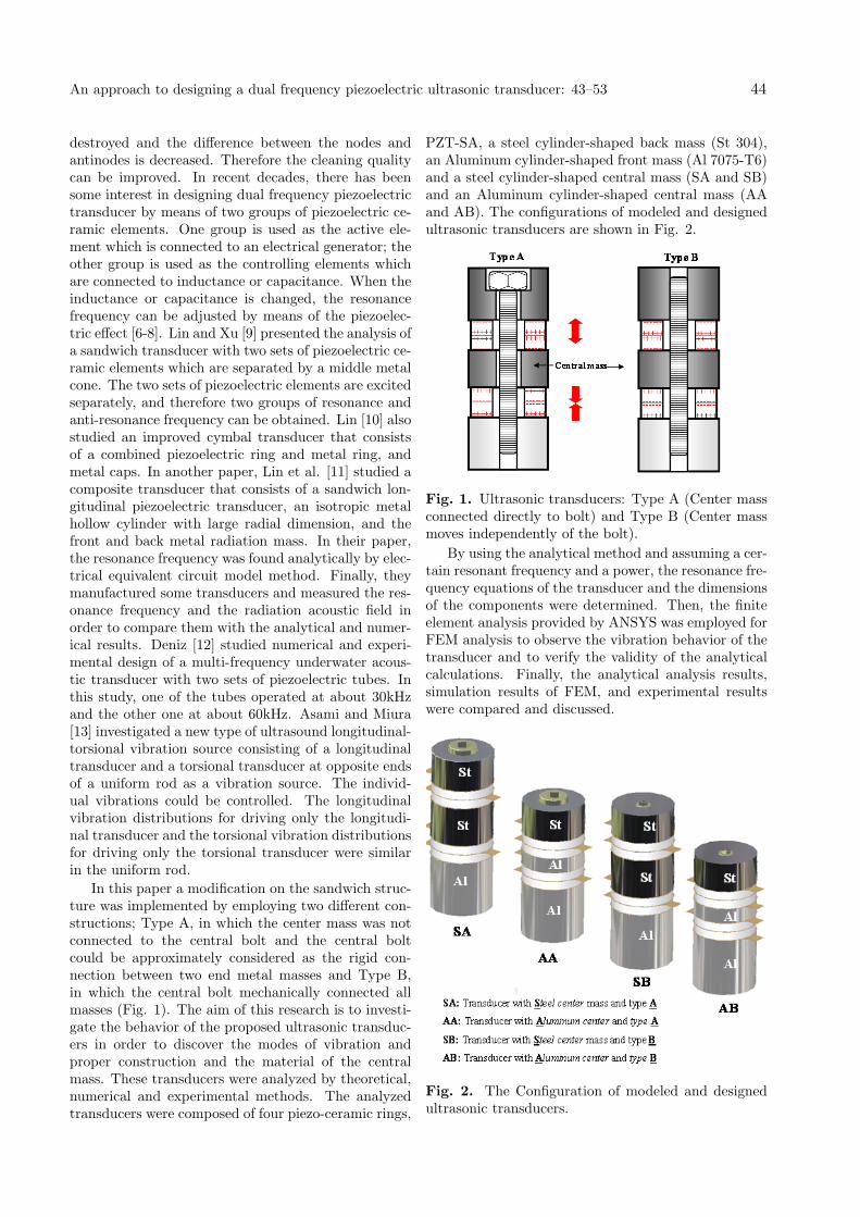
In this paper a modification on the sandwich struc-ture was implemented by employing two different con-structions; Type A, in which the center mass was notconnected to the central bolt and the central boltcould be approximately considered as the rigid con-nection between two end metal masses and Type B,in which the central bolt mechanically connected allmasses (Fig. 1). The aim of this research is to investi-gate the behavior of the proposed ultrasonic transduc-ers in order to discover the modes of vibration andproper construction and the material of the centralmass. These transducers were analyzed by theoretical,numerical and experimental methods. The analyzedtransducers were composed of four piezo-ceramic rings,
PZT-SA, a steel cylinder-shaped back mass (St 304),an Aluminum cylinder-shaped front mass (Al 7075-T6)and a steel cylinder-shaped central mass (SA and SB)and an Aluminum cylinder-shaped central mass (AAand AB). The configurations of modeled and designedultrasonic transducers are shown in Fig. 2.
Fig. 1. Ultrasonic transducers: Type A (Center massconnected directly to bolt) and Type B (Center massmoves independently of the bolt).
By using the analytical method and assuming a cer-tain resonant frequency and a power, the resonance fre-quency equations of the transducer and the dimensionsof the components were determined. Then, the finiteelement analysis provided by ANSYS was employed forFEM analysis to observe the vibration behavior of thetransducer and to verify the validity of the analyticalcalculations. Finally, the analytical analysis results,simulation results of FEM, and experimental resultswere compared and discussed.
Fig. 2. The Configuration of modeled and designedultrasonic transducers.
An approach to designing a dual frequency piezoelectric ultrasonic transducer: 43–53 44
2. Theoretical Analysis of the Dual Fre-quency Piezoelectric Transducer
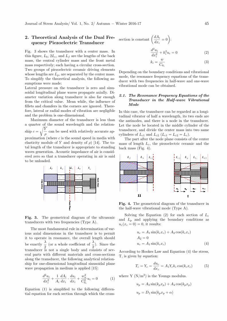
Fig. 3 shows the transducer with a center mass. Inthis figure, Lb, 2Lc, and Lf are the lengths of the backmass, the central cylinder mass and the front metalmass respectively; each having a circular cross-section.Two groups of piezoelectric ceramic driving elementswhose lengths are Lp, are separated by the center mass.To simplify the theoretical analysis, the following as-sumptions were made:Lateral pressure on the transducer is zero and sinu-soidal longitudinal plane waves propagate axially. Di-ameter variation along transducer is also far enoughfrom the critical value. Mean while, the influence offillets and chamfers in the corners are ignored. There-fore, lateral or radial modes of vibration are negligibleand the problem is one-dimensional.
Maximum diameter of the transducer is less thana quarter of the sound wavelength and the relation-
ship c =
√Y
ρcan be used with relatively accurate ap-
proximation (where c is the sound speed in media withelasticity module of Y and density of ρ) [14]. The to-tal length of the transducer is appropriate to standingwaves generation. Acoustic impedance of air is consid-ered zero so that a transducer operating in air is saidto be unloaded.
Fig. 3. The geometrical diagram of the ultrasonictransducers with two frequencies (Type A).
The most fundamental rule in determination of var-ious axial dimensions in the transducer is to permitit to operate in resonance, the overall length should
be exactlyλ
2(or a whole coefficient of
λ
2). Since the
transducer is not a single body and consists of sev-eral parts with different materials and cross-sectionsalong the transducer, the following analytical relation-ship for one-dimensional longitudinal sinusoidal planewave propagation in medium is applied [15]:
d2ui
dx2i
+1
Ai
dAi
dxi· dui
dxi+
w2n
C20i
ui = 0 (1)
Equation (1) is simplified to the following differen-tial equation for each section through which the cross-
section is constant
(dAi
dxi= 0
):
d2ui
dx2i
+ k2i ui = 0 (2)
ki =w
C0i
(3)
Depending on the boundary conditions and vibrationalmode, the resonance frequency equations of the trans-ducer with two frequencies in half-wave and one-wavevibrational mode can be obtained.
2.1. The Resonance Frequency Equations of theTransducer in the Half-wave VibrationalMode
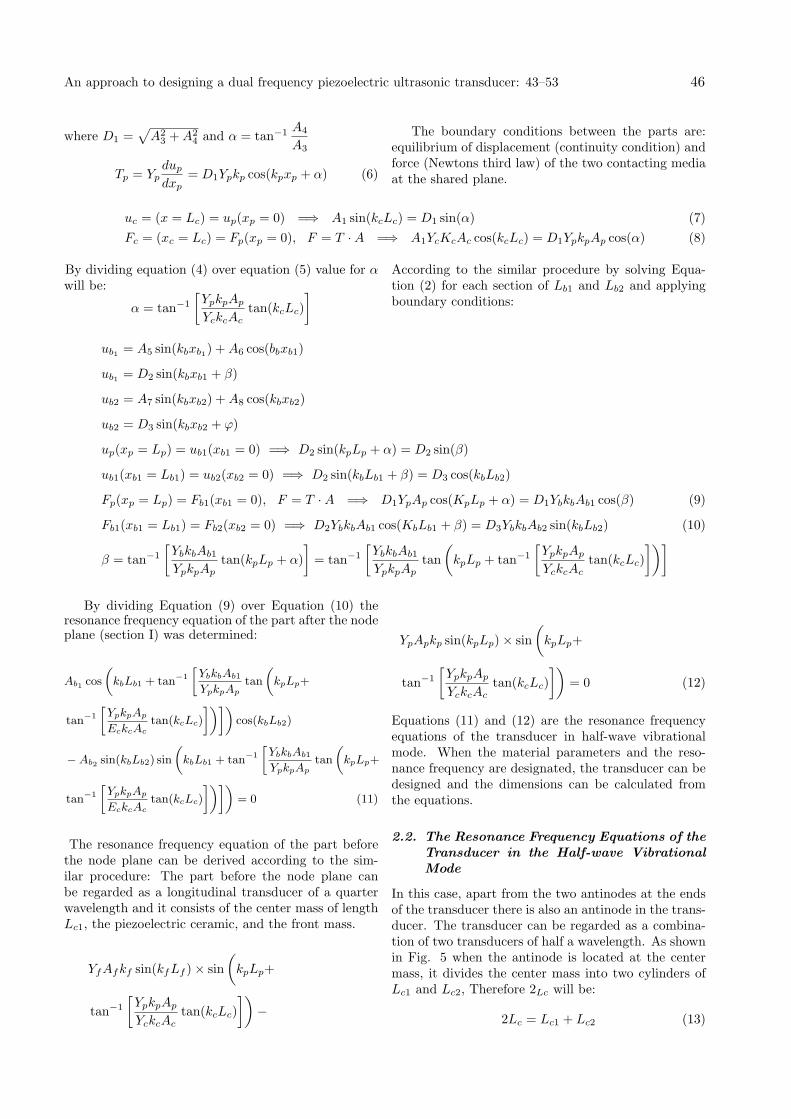
In this case, the transducer can be regarded as a longi-tudinal vibrator of half a wavelength, its two ends arethe antinodes, and there is a node in the transducer.Let the node be located in the middle cylinder of thetransducer, and divide the center mass into two samecylinders of Lc1 and Lc2 (Lc1 = Lc2 = Lc).
The part after the node plane consists of the centermass of length Lc, the piezoelectric ceramic and theback mass (Fig. 4).
Fig. 4. The geometrical diagram of the transducer inthe half-wave vibrational mode (Type A).
Solving the Equation (2) for each section of Lc
and Lp and applying the boundary conditions asuc(xc = 0) = 0, it results:
uc = A1 sin(kcxc) +A2 cos(kcxc)
A2 = 0
uc = A1 sin(kcxc) (4)
According to Hookes Law and Equation (4) the stress,T, is given by equation:
Tc = Yc =duc
dxc= A1Yckc cos(kcxc) (5)
where Y (N/m2) is the Youngs modulus.
up = A3 sin(kpxp) +A4 cos(kpxp)
up = D1 sin(kpxp + α)
Journal of Stress Analysis/ Vol. 1, No. 2/ Autumn − Winter 2016-17 45
where D1 =√A2
3 +A24 and α = tan−1 A4
A3
Tp = Ypdup
dxp= D1Ypkp cos(kpxp + α) (6)
The boundary conditions between the parts are:equilibrium of displacement (continuity condition) andforce (Newtons third law) of the two contacting mediaat the shared plane.
uc = (x = Lc) = up(xp = 0) =⇒ A1 sin(kcLc) = D1 sin(α) (7)
Fc = (xc = Lc) = Fp(xp = 0), F = T ·A =⇒ A1YcKcAc cos(kcLc) = D1YpkpAp cos(α) (8)
By dividing equation (4) over equation (5) value for αwill be:
α = tan−1
[YpkpAp
YckcActan(kcLc)
] According to the similar procedure by solving Equa-tion (2) for each section of Lb1 and Lb2 and applyingboundary conditions:
ub1 = A5 sin(kbxb1) +A6 cos(bbxb1)
ub1 = D2 sin(kbxb1 + β)
ub2 = A7 sin(kbxb2) +A8 cos(kbxb2)
ub2 = D3 sin(kbxb2 + φ)
up(xp = Lp) = ub1(xb1 = 0) =⇒ D2 sin(kpLp + α) = D2 sin(β)
ub1(xb1 = Lb1) = ub2(xb2 = 0) =⇒ D2 sin(kbLb1 + β) = D3 cos(kbLb2)
Fp(xp = Lp) = Fb1(xb1 = 0), F = T ·A =⇒ D1YpAp cos(KpLp + α) = D1YbkbAb1 cos(β) (9)
Fb1(xb1 = Lb1) = Fb2(xb2 = 0) =⇒ D2YbkbAb1 cos(KbLb1 + β) = D3YbkbAb2 sin(kbLb2) (10)
β = tan−1
[YbkbAb1
YpkpAptan(kpLp + α)
]= tan−1
[YbkbAb1
YpkpAptan
(kpLp + tan−1
[YpkpAp
YckcActan(kcLc)
])]
By dividing Equation (9) over Equation (10) theresonance frequency equation of the part after the nodeplane (section I) was determined:
Ab1 cos
(kbLb1 + tan−1
[YbkbAb1
YpkpAptan
(kpLp+
tan−1
[YpkpAp
EckcActan(kcLc)
])])cos(kbLb2)
−Ab2 sin(kbLb2) sin
(kbLb1 + tan−1
[YbkbAb1
YpkpAptan
(kpLp+
tan−1
[YpkpAp
EckcActan(kcLc)
])])= 0 (11)
The resonance frequency equation of the part beforethe node plane can be derived according to the sim-ilar procedure: The part before the node plane canbe regarded as a longitudinal transducer of a quarterwavelength and it consists of the center mass of lengthLc1, the piezoelectric ceramic, and the front mass.
YfAfkf sin(kfLf )× sin
(kpLp+
tan−1
[YpkpAp
YckcActan(kcLc)
])−
YpApkp sin(kpLp)× sin
(kpLp+
tan−1
[YpkpAp
YckcActan(kcLc)
])= 0 (12)
Equations (11) and (12) are the resonance frequencyequations of the transducer in half-wave vibrationalmode. When the material parameters and the reso-nance frequency are designated, the transducer can bedesigned and the dimensions can be calculated fromthe equations.
2.2. The Resonance Frequency Equations of theTransducer in the Half-wave VibrationalMode
In this case, apart from the two antinodes at the endsof the transducer there is also an antinode in the trans-ducer. The transducer can be regarded as a combina-tion of two transducers of half a wavelength. As shownin Fig. 5 when the antinode is located at the centermass, it divides the center mass into two cylinders ofLc1 and Lc2, Therefore 2Lc will be:
2Lc = Lc1 + Lc2 (13)
An approach to designing a dual frequency piezoelectric ultrasonic transducer: 43–53 46
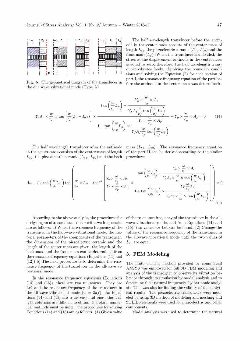
Fig. 5. The geometrical diagram of the transducer inthe one wave vibrational mode (Type A).
The half wavelength transducer before the antin-ode in the center mass consists of the center mass oflength Lc1, the piezoelectric ceramic (L′
p1, L′p2) and the
front mass (Lf ). When the transducer is unloaded, thestress at the displacement antinode in the center massis equal to zero, therefore, the half wavelength trans-ducer vibrates freely. Applying the boundary condi-tions and solving the Equation (2) for each section ofpart I, the resonance frequency equation of the part be-fore the antinode in the center mass was determined:
YcAc ×w
cc× tan
[w
cc(Lc − Lc1)
]×
tan
(w
cpLp
)−
Yp ×w
cp×Ap
YfAfw
cftan
(w
cfLf
)
1 + tan
(w
cpLp
)×
Yp ×w
cp×Ap
YfAfw
cftan
(w
cfLf
)− Yp ×
w
cp×Ap = 0 (14)
The half wavelength transducer after the antinodein the center mass consists of the center mass of lengthLc2, the piezoelectric ceramic (Lp1, Lp2) and the back
mass (Lb1, Lb2). The resonance frequency equationof the part II can be derived according to the similarprocedure:
Ab1 −Ab2 tan
(w
cbLb2
)tan
w
cb× Lb1 + tan−1
Yb ×
w
cb×Ab1
Yb ×w
cp×Ap
×
tan
(w
cpLp
)−
Yp × w
cp×AP
YcAc ×w
cc× tan
(w
ccLc1
)
1 + tan
(w
cpLp
)×
YPw
cpAp
YcAc ×w
cc× tan
(w
ccLc1
)
= 0
(15)
According to the above analysis, the procedures fordesigning an ultrasonic transducer with two frequenciesare as follows. a) When the resonance frequency of thetransducer in the half-wave vibrational mode, the ma-terial parameters of the components of the transducer,the dimensions of the piezoelectric ceramic and thelength of the center mass are given, the length of theback mass and the front mass can be determined fromthe resonance frequency equations (Equations (11) and(12)) b) The next procedure is to determine the reso-nance frequency of the transducer in the all-wave vi-brational mode.
In the resonance frequency equations (Equations(14) and (15)), there are two unknowns. They areLc1 and the resonance frequency of the transducer inthe all-wave vibrational mode (w = 2πf). As Equa-tions (14) and (15) are transcendental ones, the ana-lytic solutions are difficult to obtain; therefore, numer-ical methods must be used. The procedures for solvingEquations (14) and (15) are as follows. (1) Give a value
of the resonance frequency of the transducer in the all-wave vibrational mode, and from Equations (14) and(15), two values for Lc1 can be found. (2) Change thevalues of the resonance frequency of the transducer inthe all-wave vibrational mode until the two values ofLc1 are equal.
3. FEM Modeling
The finite element method provided by commercialANSYS was employed for full 3D FEM modeling andanalysis of the transducer to observe its vibration be-havior through its simulation by modal analysis and todetermine their natural frequencies by harmonic analy-sis. This was also for finding the validity of the analyt-ical results. The piezoelectric transducers were mod-eled by using 3D method of modeling and meshing andSOLID5 elements were used for piezoelectric and othercomponents.
Modal analysis was used to determine the natural
Journal of Stress Analysis/ Vol. 1, No. 2/ Autumn − Winter 2016-17 47
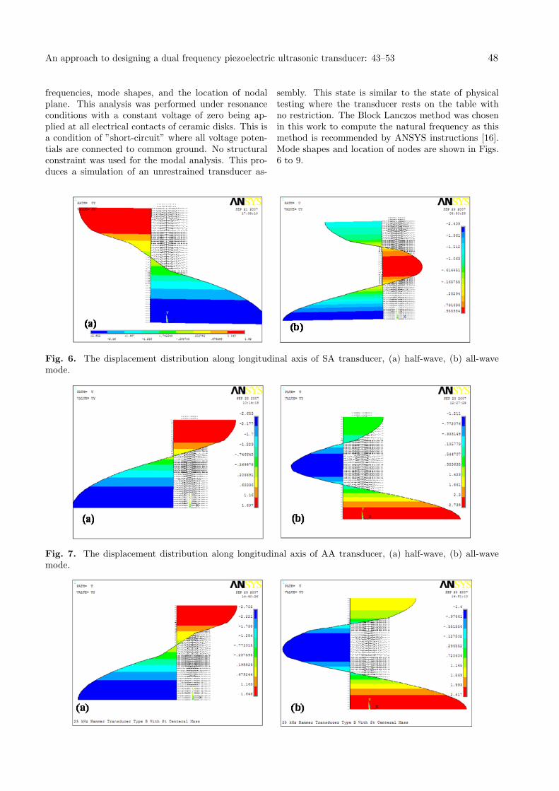
frequencies, mode shapes, and the location of nodalplane. This analysis was performed under resonanceconditions with a constant voltage of zero being ap-plied at all electrical contacts of ceramic disks. This isa condition of ”short-circuit” where all voltage poten-tials are connected to common ground. No structuralconstraint was used for the modal analysis. This pro-duces a simulation of an unrestrained transducer as-
sembly. This state is similar to the state of physicaltesting where the transducer rests on the table withno restriction. The Block Lanczos method was chosenin this work to compute the natural frequency as thismethod is recommended by ANSYS instructions [16].Mode shapes and location of nodes are shown in Figs.6 to 9.
Fig. 6. The displacement distribution along longitudinal axis of SA transducer, (a) half-wave, (b) all-wavemode.
Fig. 7. The displacement distribution along longitudinal axis of AA transducer, (a) half-wave, (b) all-wavemode.
An approach to designing a dual frequency piezoelectric ultrasonic transducer: 43–53 48
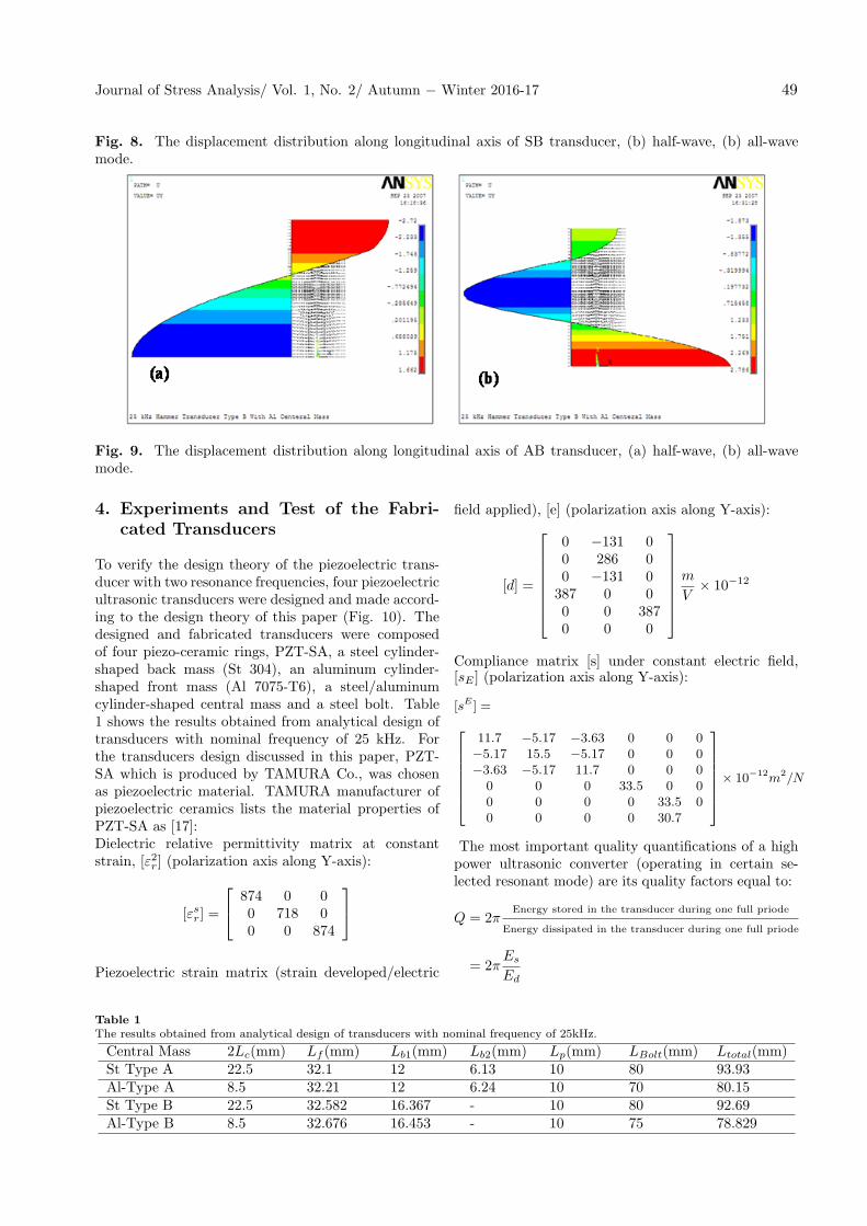
Fig. 8. The displacement distribution along longitudinal axis of SB transducer, (b) half-wave, (b) all-wavemode.
Fig. 9. The displacement distribution along longitudinal axis of AB transducer, (a) half-wave, (b) all-wavemode.
4. Experiments and Test of the Fabri-cated Transducers
To verify the design theory of the piezoelectric trans-ducer with two resonance frequencies, four piezoelectricultrasonic transducers were designed and made accord-ing to the design theory of this paper (Fig. 10). Thedesigned and fabricated transducers were composedof four piezo-ceramic rings, PZT-SA, a steel cylinder-shaped back mass (St 304), an aluminum cylinder-shaped front mass (Al 7075-T6), a steel/aluminumcylinder-shaped central mass and a steel bolt. Table1 shows the results obtained from analytical design oftransducers with nominal frequency of 25 kHz. Forthe transducers design discussed in this paper, PZT-SA which is produced by TAMURA Co., was chosenas piezoelectric material. TAMURA manufacturer ofpiezoelectric ceramics lists the material properties ofPZT-SA as [17]:Dielectric relative permittivity matrix at constantstrain, [ε2r] (polarization axis along Y-axis):
[εsr] =
874 0 00 718 00 0 874
Piezoelectric strain matrix (strain developed/electric
field applied), [e] (polarization axis along Y-axis):
[d] =
0 −131 00 286 00 −131 0387 0 00 0 3870 0 0
m
V× 10−12
Compliance matrix [s] under constant electric field,[sE ] (polarization axis along Y-axis):
[sE ] =11.7 −5.17 −3.63 0 0 0−5.17 15.5 −5.17 0 0 0−3.63 −5.17 11.7 0 0 0
0 0 0 33.5 0 00 0 0 0 33.5 00 0 0 0 30.7
× 10−12m2/N
The most important quality quantifications of a highpower ultrasonic converter (operating in certain se-lected resonant mode) are its quality factors equal to:
Q = 2πEnergy stored in the transducer during one full priode
Energy dissipated in the transducer during one full priode
= 2πEs
Ed
Table 1The results obtained from analytical design of transducers with nominal frequency of 25kHz.
Central Mass 2Lc(mm) Lf (mm) Lb1(mm) Lb2(mm) Lp(mm) LBolt(mm) Ltotal(mm)St Type A 22.5 32.1 12 6.13 10 80 93.93Al-Type A 8.5 32.21 12 6.24 10 70 80.15St Type B 22.5 32.582 16.367 - 10 80 92.69Al-Type B 8.5 32.676 16.453 - 10 75 78.829
Journal of Stress Analysis/ Vol. 1, No. 2/ Autumn − Winter 2016-17 49
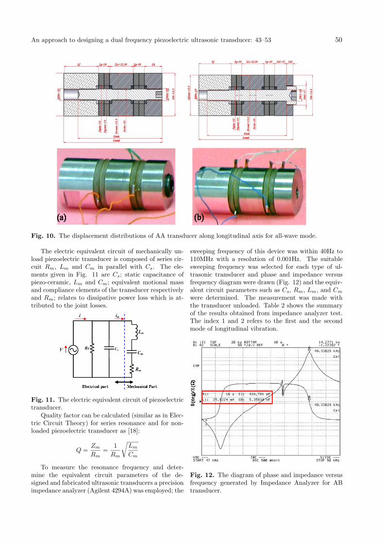
Fig. 10. The displacement distributions of AA transducer along longitudinal axis for all-wave mode.
The electric equivalent circuit of mechanically un-load piezoelectric transducer is composed of series cir-cuit Rm, Lm and Cm in parallel with Cs. The ele-ments given in Fig. 11 are Cs; static capacitance ofpiezo-ceramic, Lm and Cm; equivalent motional massand compliance elements of the transducer respectivelyand Rm; relates to dissipative power loss which is at-tributed to the joint losses.
Fig. 11. The electric equivalent circuit of piezoelectrictransducer.
Quality factor can be calculated (similar as in Elec-tric Circuit Theory) for series resonance and for non-loaded piezoelectric transducer as [18]:
Q =Zm
Rm=
1
Rm
√Lm
Cm
To measure the resonance frequency and deter-mine the equivalent circuit parameters of the de-signed and fabricated ultrasonic transducers a precisionimpedance analyzer (Agilent 4294A) was employed; the
sweeping frequency of this device was within 40Hz to110MHz with a resolution of 0.001Hz. The suitablesweeping frequency was selected for each type of ul-trasonic transducer and phase and impedance versusfrequency diagram were drawn (Fig. 12) and the equiv-alent circuit parameters such as Cs, Rm, Lm, and Cm
were determined. The measurement was made withthe transducer unloaded. Table 2 shows the summaryof the results obtained from impedance analyzer test.The index 1 and 2 refers to the first and the secondmode of longitudinal vibration.
Fig. 12. The diagram of phase and impedance versusfrequency generated by Impedance Analyzer for ABtransducer.
An approach to designing a dual frequency piezoelectric ultrasonic transducer: 43–53 50
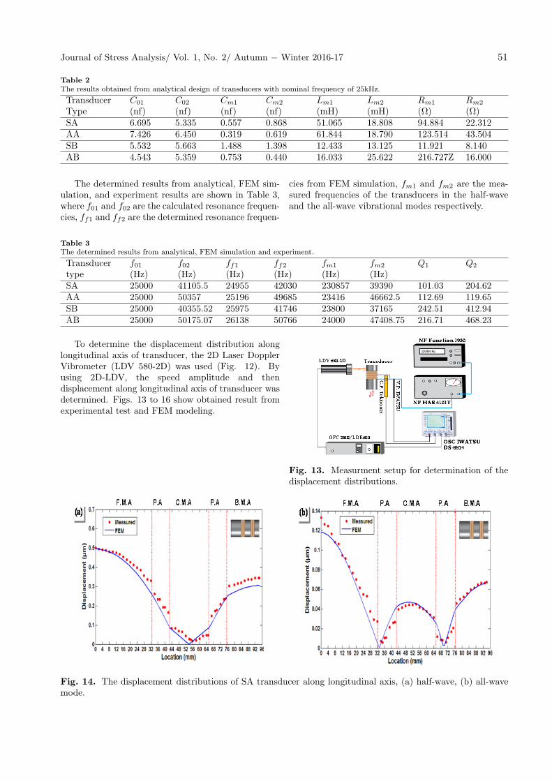
Table 2The results obtained from analytical design of transducers with nominal frequency of 25kHz.
TransducerType
C01
(nf)C02
(nf)Cm1
(nf)Cm2
(nf)Lm1
(mH)Lm2
(mH)Rm1
(Ω)Rm2
(Ω)SA 6.695 5.335 0.557 0.868 51.065 18.808 94.884 22.312AA 7.426 6.450 0.319 0.619 61.844 18.790 123.514 43.504SB 5.532 5.663 1.488 1.398 12.433 13.125 11.921 8.140AB 4.543 5.359 0.753 0.440 16.033 25.622 216.727Z 16.000
The determined results from analytical, FEM sim-ulation, and experiment results are shown in Table 3,where f01 and f02 are the calculated resonance frequen-cies, ff1 and ff2 are the determined resonance frequen-
cies from FEM simulation, fm1 and fm2 are the mea-sured frequencies of the transducers in the half-waveand the all-wave vibrational modes respectively.
Table 3The determined results from analytical, FEM simulation and experiment.
Transducertype
f01(Hz)
f02(Hz)
ff1(Hz)
ff2(Hz)
fm1
(Hz)fm2
(Hz)Q1 Q2
SA 25000 41105.5 24955 42030 230857 39390 101.03 204.62AA 25000 50357 25196 49685 23416 46662.5 112.69 119.65SB 25000 40355.52 25975 41746 23800 37165 242.51 412.94AB 25000 50175.07 26138 50766 24000 47408.75 216.71 468.23
To determine the displacement distribution alonglongitudinal axis of transducer, the 2D Laser DopplerVibrometer (LDV 580-2D) was used (Fig. 12). Byusing 2D-LDV, the speed amplitude and thendisplacement along longitudinal axis of transducer wasdetermined. Figs. 13 to 16 show obtained result fromexperimental test and FEM modeling.
Fig. 13. Measurment setup for determination of thedisplacement distributions.
Fig. 14. The displacement distributions of SA transducer along longitudinal axis, (a) half-wave, (b) all-wavemode.
Journal of Stress Analysis/ Vol. 1, No. 2/ Autumn − Winter 2016-17 51
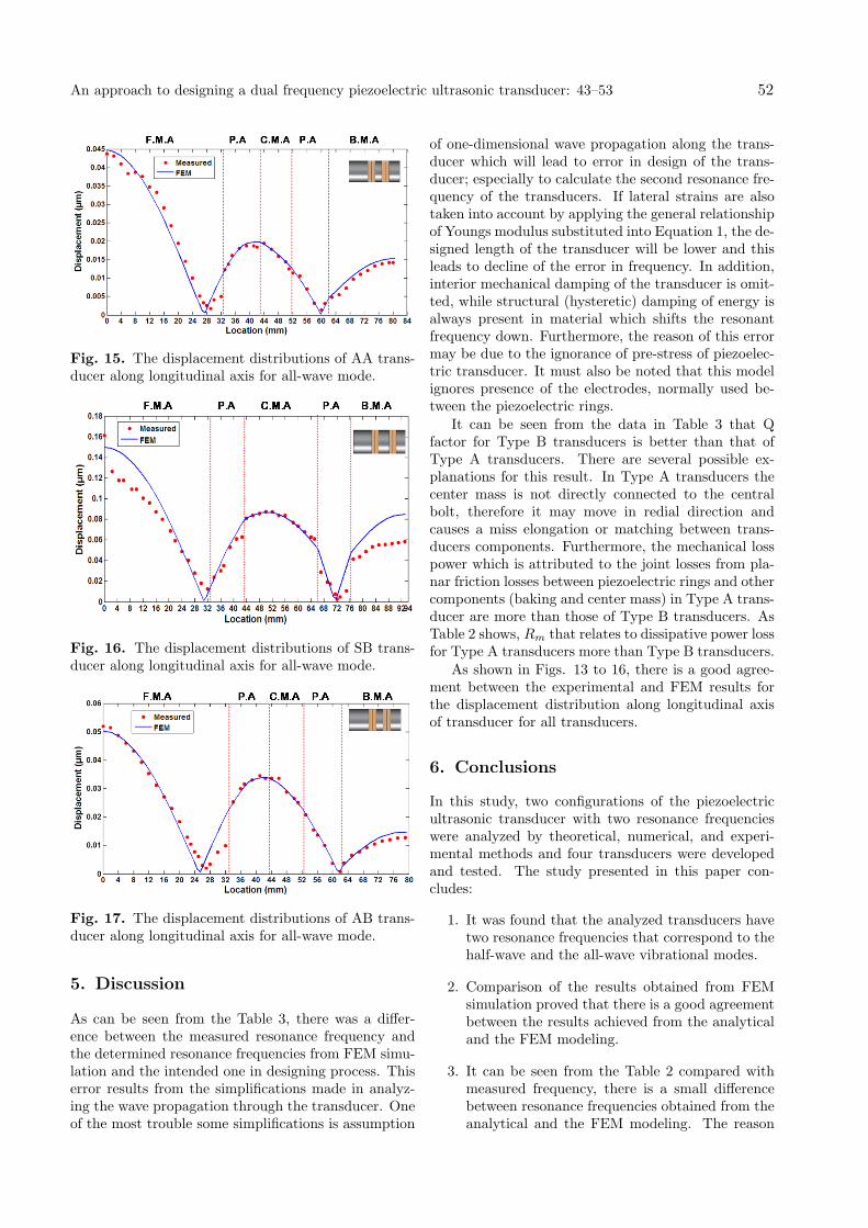
Fig. 15. The displacement distributions of AA trans-ducer along longitudinal axis for all-wave mode.
Fig. 16. The displacement distributions of SB trans-ducer along longitudinal axis for all-wave mode.
Fig. 17. The displacement distributions of AB trans-ducer along longitudinal axis for all-wave mode.
5. Discussion
As can be seen from the Table 3, there was a differ-ence between the measured resonance frequency andthe determined resonance frequencies from FEM simu-lation and the intended one in designing process. Thiserror results from the simplifications made in analyz-ing the wave propagation through the transducer. Oneof the most trouble some simplifications is assumption
of one-dimensional wave propagation along the trans-ducer which will lead to error in design of the trans-ducer; especially to calculate the second resonance fre-quency of the transducers. If lateral strains are alsotaken into account by applying the general relationshipof Youngs modulus substituted into Equation 1, the de-signed length of the transducer will be lower and thisleads to decline of the error in frequency. In addition,interior mechanical damping of the transducer is omit-ted, while structural (hysteretic) damping of energy isalways present in material which shifts the resonantfrequency down. Furthermore, the reason of this errormay be due to the ignorance of pre-stress of piezoelec-tric transducer. It must also be noted that this modelignores presence of the electrodes, normally used be-tween the piezoelectric rings.
It can be seen from the data in Table 3 that Qfactor for Type B transducers is better than that ofType A transducers. There are several possible ex-planations for this result. In Type A transducers thecenter mass is not directly connected to the centralbolt, therefore it may move in redial direction andcauses a miss elongation or matching between trans-ducers components. Furthermore, the mechanical losspower which is attributed to the joint losses from pla-nar friction losses between piezoelectric rings and othercomponents (baking and center mass) in Type A trans-ducer are more than those of Type B transducers. AsTable 2 shows, Rm that relates to dissipative power lossfor Type A transducers more than Type B transducers.
As shown in Figs. 13 to 16, there is a good agree-ment between the experimental and FEM results forthe displacement distribution along longitudinal axisof transducer for all transducers.
6. Conclusions
In this study, two configurations of the piezoelectricultrasonic transducer with two resonance frequencieswere analyzed by theoretical, numerical, and experi-mental methods and four transducers were developedand tested. The study presented in this paper con-cludes:
1. It was found that the analyzed transducers havetwo resonance frequencies that correspond to thehalf-wave and the all-wave vibrational modes.
2. Comparison of the results obtained from FEMsimulation proved that there is a good agreementbetween the results achieved from the analyticaland the FEM modeling.
3. It can be seen from the Table 2 compared withmeasured frequency, there is a small differencebetween resonance frequencies obtained from theanalytical and the FEM modeling. The reason
An approach to designing a dual frequency piezoelectric ultrasonic transducer: 43–53 52
of this error may be due to simplifying presump-tion of one-dimensional wave propagation alongthe transducer and the ignorance of pre-stress ofpiezoelectric transducer and the mechanical losspower attributed to the joint losses from planarfriction losses between piezoelectric and metalparts and to the material hysteretic-related losses(internal mechanical damping in all transducerparts).
4. There is a good agreement between the experi-mental and FEM results for the displacement dis-tribution along longitudinal axis of transducer.
5. As shown in the Table 2 that use of type B trans-ducer increased the mechanical quality factor (Q)of dual piezoelectric transducers.
6. There is a possibility of achieving the various sec-ond resonance frequencies with same first reso-nance frequency by using different center massmaterial.
7. The results obtained are showing that the capa-bilities of the ANSYS software can be used suc-cessfully as a powerful and reliable tool for pre-diction of behavior of multifrequency piezoelec-tric transducers.
Acknowledgements
The authors express their sincere appreciation to Prof.Ueha and Prof. Nakamura for their contribution inconducting some of the experiments for the research.Thanks should also be given to Precision and Intelli-gence Laboratory at Tokyo Institute of Technology forproviding experimental facilities.
References
[1] L. Shuyu, Study on the multifrequency Langevinultrasonic transducer, Ultrasonics, 33(6) (1995)445-448.
[2] Y.R. Yeon-bo Kim, New design of matching layersfor high power and wide band ultrasonic transduc-ers, Sensor. Actuator., 71 (1998) 116-122.
[3] L. Parrini, Design of advanced ultrasonic transduc-ers for welding devices, IEEE Trans. Ultrason., Fer-roelect., Freq. Control., 48(6) (2001) 1632-1639.
[4] B. Dubus, G. Haw, C. Granger, O. Ledez, Char-acterization of multilayered piezoelectric ceramicsfor high power transducers, Ultrasonics, 40 (2002)903-906.
[5] H.L.W. Chan, M.W. Ng, P.C.K. Liu, Effect ofhybrid structure (1/3 composite and ceramic) onthe performance of sandwich transducers, Mat. Sci.Eng., B99 (2003) 6-10.
[6] S. Saitoh, M. Izumi, Y. Mine, A dual frequencyultrasonic probe for medical applications, IEEETrans. Ultrason. Ferroelectr. Freq. Control, 42(1995) 294-300.
[7] G. Piazza, P.J. Stephanou, A. Pisano, Single-chipmultiple-frequency AlN MEMS filters based oncontour-mode piezoelectric resonators, J. Micro-electromech. Syst., 16 (2007) 319-28, .
[8] K. Heath Martin, B.D. Lindsey, J. Ma, M. Lee,S. Li, F.S. Foster , X. Jiang, P.A. Dayton, Dual-frequency piezoelectric transducers for contrast en-hanced ultrasound imaging, Sensors, 14 (2014)20825-20842.
[9] S. Lin, C. Xu, Analysis of the sandwich ultrasonictransducer with two sets of piezoelectric elements,Smart. Mater. Struct., 17(6) (2008) 6 065008.
[10] S. Lin, An improved cymbal transducer with com-bined piezoelectric ceramic ring and metal ring,Sensor. Actuator., 163(1) (2010) 266-276.
[11] S. Lin, L. Xu, H. Wenxu, A new type of highpower composite ultrasonic transducer, J. Sound.Vib., 330(7) (2011) 1419-1431.
[12] S. Deniz, The design of a multi-frequency under-water acoustic transducer with cylindrical piezo-electric elements, MSc Thesis. Turkey: Middle EastTechnical University; 2011.
[13] T. Asami, H. Miura, Longitudinaltorsional vibra-tion source consisting of two transducers with dif-ferent vibration modes, JPN. J. Appl. Phys., 55(2016) 7-8.
[14] J.W. Rayleigh, The Theory of Sound, New York,1945.
[15] K.F. Graff, Wave Motion in Elastic Solids, OxfordUniversity Press, 1975.
[16] R.G. Grimes, J.G. Lewis, H.D. Simon, A shiftedblock lanczos algorithm for solving sparse system-atic generalized eigenproblems, Siam. J. Matrix.Anal. Appl., 15 (1994) 228-272.
[17] Piezoelectric Ceramics for High Power Applica-tions data sheet, TAMURA CO., 2006.
[18] G.W. Taylor., J.J. Gagnepain, Piezoelectricity,New York: Gordon and Breach Science, 4 (1960).
Journal of Stress Analysis/ Vol. 1, No. 2/ Autumn − Winter 2016-17 53