an application on an alarm root cause tracking system...
TRANSCRIPT
Lee, Jung Woon
Kim, Jung Taek
I&C-Human Factors Research Center
Korea Atomic Energy Research Institute
An Application on an Alarm Root Cause Tracking System
(ACTS)
2007 IEEE HFPP/HPRCT Joint Conference

2
2007 IEEE HFPP/HPRCT Joint Conference
IntroductionConventional alarm systems in nuclear power plants
based on 'one sensor - one indicator' design no processing of alarm signals and hardwired display
cause Alarm Avalanche during plant upsetincrease Operator's Cognitive Workload
leading human error at transients
Utility Need for urgent improvement (EPRI NP-6839) –most cost effective areas
Alarm Screening and Management System On-line Root-Cause AnalyzerOn-line Thermal Performance AdvisorOn-line Tech Spec. Monitor/Advisor

3
2007 IEEE HFPP/HPRCT Joint Conference
Introduction
KAERI’s ADIOS developmentADIOS (Alarm and Diagnosis-Integrated Operator Support System) 1994 ~ 1997 : Advanced I&C Technology Development (supp. by MOST)
Dynamic Alarm Processing Systemλ Alarm Prioritizationλ Alarm Classificationλ Alarm Suppression and Filtering
2001 ~ 2005 : KNICS project (supp. by MOST and MOCIE)Improved ADIOS – process status diagnosis technologyACTS(Alarm Cause Tracking System)Plant Performance Analysis SystemSignal Fault Detection Technology
4
2007 IEEE HFPP/HPRCT Joint Conference
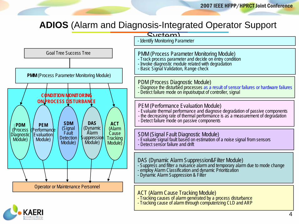
ADIOS (Alarm and Diagnosis-Integrated Operator Support System)
PMM (Process Parameter Monitoring Module)- Track process parameter and decide on entry condition- Invoke diagnostic module related with degradation- Basic Signal Validation, Range check
PDM (Process Diagnostic Module)- Diagnose the disturbed processes as a result of sensor failures or hardware failures- Detect failure mode on input/output of controller, signal
PEM (Performance Evaluation Module)- Evaluate thermal performance and diagnose degradation of passive components- the decreasing rate of thermal performance is as a measurement of degradation - Detect failure mode on passive components
SDM (Signal Fault Diagnostic Module)- Evaluate signal fault based on estimation of a noise signal from sensors- Detect sensor failure and drift
ACT (Alarm Cause Tracking Module)- Tracking causes of alarm generated by a process disturbance- Tracking cause of alarm through computerizing CLD and ARP
- Identify Monitoring Parameter
DAS (Dynamic Alarm Suppression&Filter Module)- Suppress and filter a nuisance alarm and temporary alarm due to mode change- employ Alarm Classification and dynamic Prioritization- Dynamic Alarm Suppression & Filter
PDM(Process
DiagnosticModule)
PEM(Performance
EvaluationModule)
SDM(SignalFault
DetectionModule)
ACT(AlarmCause
TrackingModule)
DAS(Dynamic
AlarmSuppression
Module)
Goal Tree Success Tree
Operator or Maintenance Personnel
PMM (Process Parameter Monitoring Module)
CONDITION MONITORING ON PROCESS DISTURBANCE

5
2007 IEEE HFPP/HPRCT Joint Conference
ACTS (Alarm Cause Tracking System)
Display of Precedent Alarms
ARP with the cause
Logic diagram- alarm cause tracking
6
2007 IEEE HFPP/HPRCT Joint Conference
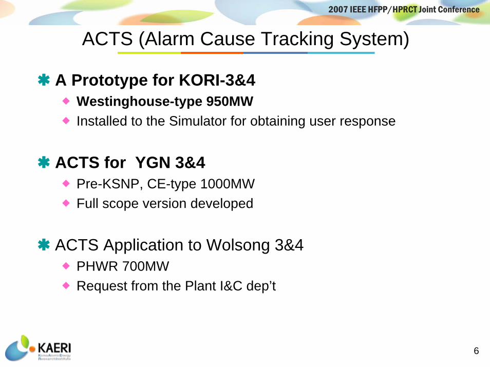
ACTS (Alarm Cause Tracking System)
A Prototype for KORI-3&4 Westinghouse-type 950MW Installed to the Simulator for obtaining user response
ACTS for YGN 3&4Pre-KSNP, CE-type 1000MWFull scope version developed
ACTS Application to Wolsong 3&4PHWR 700MWRequest from the Plant I&C dep’t

7
2007 IEEE HFPP/HPRCT Joint Conference
Issues of Alarm System in Wolsong Plant
Too many numbers (>50) of alarm tiles in a matrixNo grouping by channels – difficulty in readabilityMany combined alarms in a tileInconsistency in the use of abbreviation and terminology – both in alarm tiles and in CRT alarm lists Too small letters, use of inconsistent fonts and not well readable fontsSome legends use more than 4 linesLong words in alarm legends

8
2007 IEEE HFPP/HPRCT Joint Conference
Issues of Alarm System in Wolsong Plant
Max. 40 lines with 2 CRTsDifficulty in reading alarms bursting in more than one page during transientsNot good readability – all capital letters, no grouping, use of old-fashioned CRT fonts
9
2007 IEEE HFPP/HPRCT Joint Conference
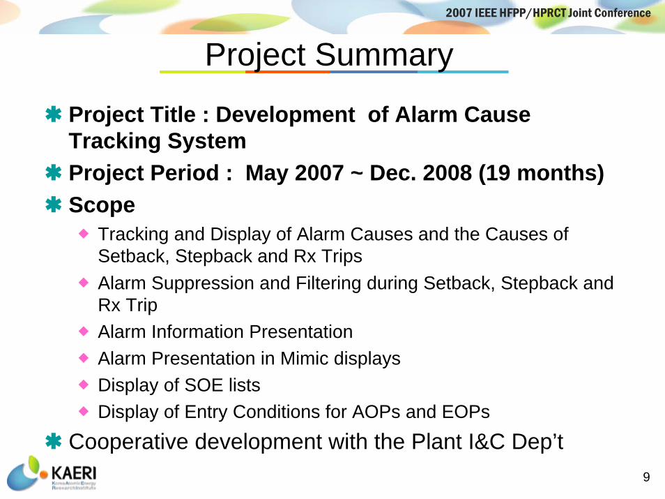
Project Summary
Project Title : Development of Alarm Cause Tracking SystemProject Period : May 2007 ~ Dec. 2008 (19 months)Scope
Tracking and Display of Alarm Causes and the Causes of Setback, Stepback and Rx TripsAlarm Suppression and Filtering during Setback, Stepback and Rx TripAlarm Information PresentationAlarm Presentation in Mimic displaysDisplay of SOE listsDisplay of Entry Conditions for AOPs and EOPs
Cooperative development with the Plant I&C Dep’t

10
2007 IEEE HFPP/HPRCT Joint Conference
Tracking an Alarm CauseComputerize the control logic diagram for tracking alarm cause during abnormal operation
Computerize the control logic diagrams (CLDs)Link signals of alarms, status or condition of components to input points of logic diagramsTracking an alarm cause through tracking the logic diagrams when a new alarm occurs
Tracking an alarm cause through logic diagram
11
2007 IEEE HFPP/HPRCT Joint Conference
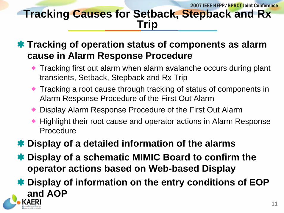
Tracking Causes for Setback, Stepback and Rx Trip
Tracking of operation status of components as alarm cause in Alarm Response Procedure
Tracking first out alarm when alarm avalanche occurs during plant transients, Setback, Stepback and Rx TripTracking a root cause through tracking of status of components in Alarm Response Procedure of the First Out Alarm Display Alarm Response Procedure of the First Out Alarm Highlight their root cause and operator actions in Alarm Response Procedure
Display of a detailed information of the alarmsDisplay of a schematic MIMIC Board to confirm the operator actions based on Web-based DisplayDisplay of information on the entry conditions of EOP and AOP

12
2007 IEEE HFPP/HPRCT Joint Conference
Moderator Temp AbnormalPL5-1
PZR Level Lo
PZR Level Hi
PZR Press Lo
Display of a root cause of Setback through tracking of status of components in operation procedure :CCW Cooling Control Valve xxx-CVxx Close
Tracking a logic diagram of a cause of Setback :Highlight a root cause of SetbackDisplay Alarm Response Procedure
Display of a root cause of Setback
Tracking Causes for Setback, Stepback and Rx Trip

13
2007 IEEE HFPP/HPRCT Joint Conference
Alarm Processing TechniquesAlarm Prioritization
- Default priority according to its importance- To adopt a criteria of Alarm Priority of Wolsong NPPs
Red - Safety AlarmYellow - Major AlarmCyan - Minor AlarmGreen - Return to normal
To filter or suppress unimportant or nuisance alarmsPlant Mode Dependency Processing : plant operation mode
Suppressing a temporary, usual and nuisance alarms activated as a consequence of the plant mode change
Multi-setpoint Relationship Processing : unserious alarm prior to currently activated alarm from the same process variable
Suppressing a unserious alarm prior to the currently activated alarmCause-Consequence Relationships Processing
Suppressing a consequential alarm activated as a consequence of a causal alarm
14
2007 IEEE HFPP/HPRCT Joint Conference
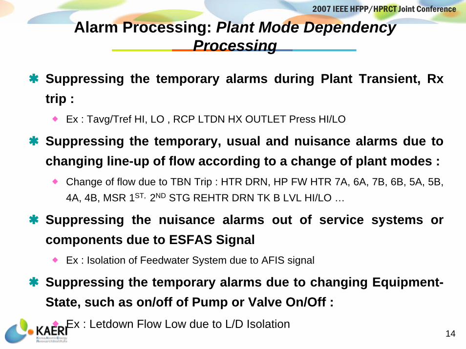
Alarm Processing: Plant Mode Dependency Processing
Suppressing the temporary alarms during Plant Transient, Rx trip :
Ex : Tavg/Tref HI, LO , RCP LTDN HX OUTLET Press HI/LO
Suppressing the temporary, usual and nuisance alarms due to changing line-up of flow according to a change of plant modes :
Change of flow due to TBN Trip : HTR DRN, HP FW HTR 7A, 6A, 7B, 6B, 5A, 5B, 4A, 4B, MSR 1ST, 2ND STG REHTR DRN TK B LVL HI/LO …
Suppressing the nuisance alarms out of service systems or components due to ESFAS Signal
Ex : Isolation of Feedwater System due to AFIS signal
Suppressing the temporary alarms due to changing Equipment-State, such as on/off of Pump or Valve On/Off :
Ex : Letdown Flow Low due to L/D Isolation
15
2007 IEEE HFPP/HPRCT Joint Conference
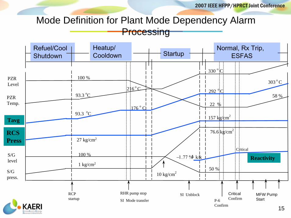
Mode Definition for Plant Mode Dependency Alarm Processing
Tavg
PZR Temp.
S/G level
S/G press.
PZR Level
58 %
303 o C
CriticalConfirm P-6
Confirm
93.3 oC
93.3 oC
176 o C
330 o C
292 o C
27 kg/cm2
100 %
50 %
157 kg/cm2
10 kg/cm2
76.6 kg/cm2
1 kg/cm2
−1.77 % k/kCritical
216 o C
Heatup/Cooldown Startup
Normal, Rx Trip, ESFAS
100 %
22 %
SI Unblock
Reactivity
RCP startup
RHR pump stop
SI Mode transfer MFW Pump Start
RCS Press
Refuel/Cool Shutdown
16
2007 IEEE HFPP/HPRCT Joint Conference
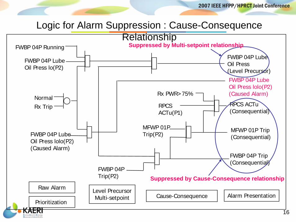
Logic for Alarm Suppression : Cause-Consequence Relationship
FWBP 04P Lube Oil Press lo(P2)
NormalRx Trip
FWBP 04P Running
FWBP 04P Lube Oil Press lolo(P2)(Caused Alarm)
RPCS ACTu(Consequential)
MFWP 01P Trip(Consequential)
FWBP 04P Trip(Consequential)
RPCS ACTu(P1)
Rx PWR>75%
MFWP 01P Trip(P2)
FWBP 04P Trip(P2)
FWBP 04P Lube Oil Press(Level Precursor)
FWBP 04P Lube Oil Press lolo(P2)(Caused Alarm)
Raw Alarm
Prioritization Alarm PresentationCause-Consequence
Level PrecursorMulti-setpoint
Suppressed by Cause-Consequence relationship
Suppressed by Multi-setpoint relationship

17
2007 IEEE HFPP/HPRCT Joint Conference
Alarm Processing Sequence
Phase 1 Alarm Activation and Tracking(Setpoint checking by rule)
If activated, check alarm priority, track input signal in CLD,track an alarm cause and check status of components, then go to phase 2
If deactivated, reset from alarm processing condition.
Phase 2 Alarm Suppression(Procedure calls on each condition)
Suppressing AL(currently activated alarm)on conditions of : mode dependency relationship
: cause-consequence relationshipSuppressing BL(level precursor of AL )
on the condition of level-precursor relationshipAnd then put AL and BL into lists of alarm processingGo to Phase 3
18
2007 IEEE HFPP/HPRCT Joint Conference
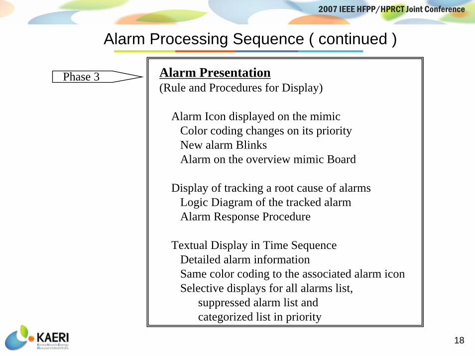
Phase 3 Alarm Presentation(Rule and Procedures for Display)
Alarm Icon displayed on the mimicColor coding changes on its priorityNew alarm BlinksAlarm on the overview mimic Board
Display of tracking a root cause of alarmsLogic Diagram of the tracked alarmAlarm Response Procedure
Textual Display in Time SequenceDetailed alarm informationSame color coding to the associated alarm iconSelective displays for all alarms list,
suppressed alarm list and categorized list in priority
Alarm Processing Sequence ( continued )

19
2007 IEEE HFPP/HPRCT Joint Conference
Display for tracking alarm cause and Operation Procedure
Display for alarm logic
Alarm Cause Tracking by linking the operating state to presented alarm
or alarm procedures
Logic tracking operating state of component for alarm cause
Link operating state to presented alarm

20
2007 IEEE HFPP/HPRCT Joint Conference
Detailed Schematic MIMIC Display

21
2007 IEEE HFPP/HPRCT Joint Conference
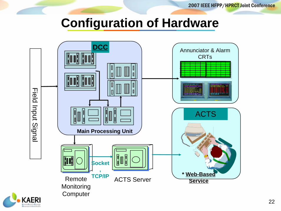
Configuration of Hardware
ACTS has been configured separately from the existing control computer DCC and AnnunciatorWindows.
Signals for processing and tracking an alarm enter ACTS from the Remote Monitoring Computer through the TCP/IP Protocol.
ACTS consists of one processing server and two CRTs.
ACTS will be implemented in a Web-based System for the use in MCR and Site Offices.
22
2007 IEEE HFPP/HPRCT Joint Conference
Annunciator & Alarm CRTs
Field Input Signal
Remote Monitoring Computer
ACTS
Main Processing Unit
DCC
Socket,
TCP/IP ACTS Server * Web-Based
Service
Configuration of Hardware

23
2007 IEEE HFPP/HPRCT Joint Conference
Conclusion
Alarm Root Cause Tracking System (ACTs) integrated with the Alarm Suppression and Filtering Techniques
To be applied to the Wolsong 3&4 CANDU Nuclear Power Plant
To solve alarm avalanche during plant transients
To reduce operator's cognitive workload.
Can improve the conventional alarm systems in nuclear power plants

24
2007 IEEE HFPP/HPRCT Joint Conference
Thank you!