an analytical investigati the performance of solar ... · an analytical investigati the performance...
TRANSCRIPT
NASA Contractor Report 3111
An Analytical Investigati
the Performance of Solar Collectors as Nighttime Heat Radiators in Airconditioning Cycles
Clay B. Jones and Frederick 0, Smetana
CONTRACT NASl-14208 MARCY 1979
-
,-- -.,
https://ntrs.nasa.gov/search.jsp?R=19790012348 2018-06-22T18:26:13+00:00Z

-
NASA Contractor Report 3111
TECH LIBRARY KAFB, NM
An Analytical Investigation of the Performance of Solar Collectors as Nighttime Heat Radiators in Airconditioning Cycles
Clay B. Jones and Frederick 0. Smetana North Carolha Science and Techzology Research Center Research Triangle Park, North Caroliua
Prepared for Langley Research Center under Contract NAS l-14208
nJnsA National Aeronautics and Space Administration
Scientific and Technical Information Office
1979


TABLE OF CONTENTS Page
NOMENCLATURE . . . . . . . . . . . . . . . . . . . . . . . . . . . v
SUMMARY . . . . . . . . . . . . . . . . . . . . . . . . . . . . . 1
INTRODUCTION . . . . . . . . . . . . . . . . . . . . . . . . . . . 2
COOLING MODE ANALYSIS . . . . . . . . . . . . . . . . . . . . . . 4
RESULTS OF COOLING MODE ANALYSIS . . . . . . . . . . . . . . . . . 21
CONCLUSION . . . . . . . . . . . . . . . . . . . . . . . . . . . . 41
BIBLIOGRAPHY . . . . . . . . . . . . . . . . . . . . . . . . . . . 43
APPENDIX. . . . . . . . . . . . . . . . . . . . . . . . . . . . . 44
i i i


NOMENCLATURE
Ac C
P
COP
COPh
COPc
d
dl
d2
9
gx
hi’ i = 1
h c, p-s
h c,p-c
k . ml
. m2
Nu
P
‘a
Q gap 1
Collector area, m2
J Specific heat coefficient, -
Kg K
Coefficient of performance, dimensionless
Heating mode COP
Cooling mode COP
Distance between collector plate and cover, m
d for gap 1
d for gap 2
Acceleration due to gravity, m/sec2
g in the ‘lx” d i rect ion
4 Enthalpy of refrigerant at various points in the cycle, KJ/Kg
Convection heat transfer to surroundings, W/m2 K
Convection heat transfer to cover, W/m2 K
coefficient, col lector plate
coefficient, col lector plate
Thermal conductivity of air, W/m K
Mass flow rate through gap 1, Kg/set
Mass flow rate through gap 2, Kg/set
Nusselt number, dimensionless
Pressure, Bars
Atmospheric pressure, Bars (I bar = I05 Pa)
Net heat dissipated through gap 1, W

Q gap 2
ggap 1
‘gap 2
qtot i’ i
9 v-s
9 c, p-c
4 c, P-s
9 c,c-s
9 r,c-s
9 w-c
R
Ra
T
Ti, i = 1
Ta
TC
T P
TS
Tol
Net heat dissipated through gap 2, W
Heat dissipated through gap 1 per unit area of col- I ector, W/m2
Heat dissipated through gap 2 per unit area of col- I ector, W/m2
= 1 - 4 Heat dissipated from collector geometry ‘Ii” per unit area of collector, W/m2
Radiation heat transfer from the collector plate to the sky, W/m2
from the collector plate to
from the collector plate to
from the cover to the sur-
Convection heat transfer the cover, W/m2
Convection heat transfer the surroundings, W/m2
Convection heat transfer round i ngs, W/m2
Radiation heat transfer from the cover to the sky, W/m2
Radiation heat transfer from the collector plate to the cover, W/m2
J Gas constant for air, -
- 3
Rayleigh number, dimensionless
Temperature, K
Temperature at various points in the cycle, K
Amb ient temperature, K
Cover temperature, K
Col lector plate temperature, K
Effective black-body sky temperature, K
Bulk fluid temperature at exit of gap 1, K
vi

T02
T !31
T 92
U
u1
u2
u - u1
-6 2
V
V
W
X
Y
a
P
AT
EP
E C
8
1-1
V
P
Bulk fluid temperature to exit of gap 2, K
Ai r temperature across gap 1, K
Ai r temperature across gap 2, K
Velocity in the “x” direction, m/set
Velocity in the “x” direction through gap 1, m/set
Velocity in the “x” direction through gap 2, m/set
Mean air velocity
U for gap 1, m/set
i for gap 2, m/set
in the “x1’ d i rection, m/set
Wind speed, m/set
Velocity in the “y” direction,
Col lector width, m
Direction along the plate
Direction perpendicular to the
Molecular thermal diffusivity,
m/set
“x” d i rect ion
m2/sec
Volume coefficient of expansion l/ K
Temperature difference, K
Collector plate emi ttance, dimensionless
Cover emittance, di mensionless
Collector tilt ang e, degrees
Dynamic viscosity, N sec/m2
Kinematic viscosity, m2/sec
Density, $$
‘a Atmospheric density
vi i

Density at bulk fluid temperature, 3
W Stefan-Boltzmann constant, m2 oK
vi i i

SUMMARY
An analytical investigation was carried out to determine the ability
of typical solar collectors to serve as nighttime heat radiators. Such
use might be made of the collectors during the summertime where they then
serve as the condenser in a heat pump cycle with electrically-driven
mechan i ca I compressor. In winter the col lectors form a solar-heated
evaporator in the heat pump cycle. It was found that if one opens the
upper and lower ends of a collector, large free convection currents may
be set up between the collector surface and the cover glassles) which can
result in appreciable heat rejection. If the collector is so designed
that both plate surfaces are exposed to convection currents when the upper
and lower ends of the collector enclosure are opened, the heat rejection
rate is 300 watts/m’ when the plate is 13OC above ambient. This is
suff cient to permit a collector array designed to provide 100% of the
heat ng needs of a home to reject the accumulated daily air conditioning
load during the course of a summer night. This also permits the overal I
energy requirement for cooling to be reduced by at least 15% and shift
the load on the utility entirely to the nighttime hours.
I NTRODUCT I ON
Using solar collectors as heat sources in heat pump cycles is a
concept that has received favorable consideration from several designers
of solar energy utilization systems. The coroi lary concept - using the
solar collectors as nighttime radiations in heat pump cooling cycles -
is scarcely mentioned. It is evident, however, that some beneficial
summertime use should be made of the solar collectors in such heating
systems in order to help justify their large capital cost. Three uses
come quickly to mind: a heat source for an absorption chiller; a source
of domestic hot water; a heat source in a Rankine cycle power unit.
The first use requires an extensive summer-winter changeover to
utilize the col
sacrifice effic
ectors efficiently in the winter. If one is willing to
ency however, the collectors can be used for direct heat-
ing (non-heat pump) in the winter with very little additional capital
cost over that for an absorption chiller. Such systems have been built
and tested at several locations.
The second use is an obvious one, but it is readily shown that the
collector area needed for winter heating is much greater than that needed
for summertime domestic hot water production. This is therefore not an
effective use of the collectors. The Rankine cycle power unit could employ
the
Pow
cat
collectors in a system to supply part
er needs in the summer, or it could dr
Systems have been built and operated
ions. Wi th presently-available techno
of the building’s electrical
ve a mechanical chiller instead.
successfully for both appli-
ogy the capital costs of a
Rankine cycle power unit are quite high because the expander particularly
and the condensate pump to a limited extent represent custom hardware that
must be desiqned and fabricated for specific conditions in specific 2
installations. Addition of a Rankine cycle power unit would add about
70% to the cost of the solar-assisted heat pump.
For these reasons a less capital-intensive use for the collectors in
the summertime was sought. It was recognized that such a use would
probably not save as much fossil fuel energy as a more capital-intensive
use, but it would probably be less difficult to maintain and more suited
to individual residential applications.
Since the solar assisted heatpump concept really implies the con-
current use of large scale thermal storage so as to provide heat at night,
on cloudy days, or for periods when the mechanical compressor cannot be
operated, it was felt that the entire cycle could easily and inexpensively
be shifted from the daytime heating mode in winter to the nighttime chill-
ing mode in summer. Under these conditions the solar collectors become
the freon condenser instead of the freon evaporator as when the system is
in the heating mode. The advantages of such operation are:
1. The system draws power from the utility at off-peak times (sunset-
to-sunrise).
2. The system COP is higher for nighttime operation than for daytime
operation because condensing temperatures may be 6-30°C lower.
It is conservatively estimated that because of these factors the power
cost for rejecting a given amount of heat can be reduced by at least 15%
compared with a conventional air conditioning system without large-scale
thermal storage. This estimate is based on the assumption that the solar
collector area needed for winter heating will in fact be sufficient to
reject all the heat necessary for summer chilling while remaining only
slightly above ambient temperature.
It was to investigate the validity of that assumption that the
following analytical study was carried out. 3
COOL I NG MODE ANALYS I S
An investigation into the heat transfer characteristics of four
collector geometries was carried out in an effort to establish probable
performance for solar collectors operating as nighttime radiators. The
col let-l-or geometries considered were:
(1) Flat plate with cover system removed (No Cover).
(2) Flat plate with one cover (Closed Cover).
(31 Flat plate with one cover and an opening between the plate
and the cover at the top and bottom of the collector
(Open End 1).
(4) Flat plate with one cover and an opening between the plate
and cover and between the plate and back insulation at the
top and bottom of the collector (Open End 2).
mod
is
was
if ications. Complete removal of the cover system during
the most desirable solution from a heat transfer standpoi
the summer
nt, but
might deemed impractical on any but very small installations. One
suggest the use of a jalousie window cover system which could be
during the summer and closed during the winter months. However,
arrangement probably increases costs to the point of overcoming
opened
such an
the
Selection of the C
desire to utilize a co
absorber and as a heat
ollector geometries stated above stems from a
lector that will perform well both as a heat
rejecter without requiring extensive seasona I
collector cost advantages afforded by the heat pump concept. Additionally,
wind loads, mechanical complexity, and increased weight pose difficulties
for a scheme of this type.

Consideration of these problems associated with cover system re-
moval suggests the need for a collector that can effectively dissipate
heat with the cover system in place. Col lector geometries (3) and (4)
above are presented as a possible means of fulfilling this requirement
without compromising heating mode performance or requiring undue mechani-
cal complexity and additional construction costs. In both configurations
the collector box sides at the top and bottom of the collector are hing-
ed so that they can be opened to allow air flow across the collector
plate. Geometry (3) employs a conventional collector arrangement with
the back insulation adjacent to the plate (see Figure t?. I n geometry
(4) the collector plate is supported by standoffs to allow flow on both
sides of the plate (see Figure 2). It was felt that by taking advan-
tage of the expected free convection draft or “chimney effect” these
types of collectors may possess adequate heat dissipation abilities.
Cooling mode operation requires that the collector subsystem func-
tion as the refrigerant condenser, rejecting heat to the atmosphere.
This heat transfer is accomplished by means of convection to the sur-
rounding air at ambient temperature and radiation from the collector to
the night sky. The effectiveness of both of these modes of heat exchange
is very difficult to predict in that they are influenced by such highly
variable parameters as wind speed, ambient temperature, atmospheric
humidity, and cloudiness. However, it was felt that reasonable operat-
ing limits could be obtained by assuming low wind speeds coupled with
very clear and very cloudy sky conditions. In addition to these re-
strictions, the following assumptions were made to simplify the heat
transfer analysis: 5

COOL AIR IN
WARM AIR OU
HINGED TOP SIDE
COLLECTOR INSULATION
COVER SUPPORT AT EDGES
/ ’ Y
HINGED BOTTOM SIDE
COOL A
FIGURE 1. Deta i I of Co I I ector Geometry 3.
/f 1 WARM AIR fNlT
‘ED
HINGED TOP SIDE
INSULATION
CIRCULAR STANDOFF
Y COVER AND PLATE SUPPORTED AT EDGES
HINGED BOTTOM SIDE
FIGURE 2. Detail of Collector Geometry 4.
-
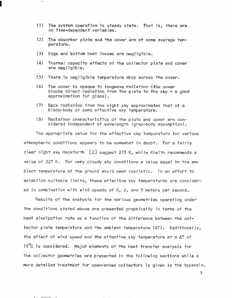
(1) The system operat ion is steady state. That no time-dependent variables.
is, there are
(2) The absorber plate and the cover are at some perature.
average tem-
(3) Edge and bottom heat losses are negI.igible.
(4) Thermal capacity effects of the collector plate and cover are negligible.
(5) There is negligible temperature drop across the cover.
(6) The cover is opaque to longwave radiation (the cover blocks direct radiation from the plate to the sky - a good approximation for glass).
(7) Back radiation from the night sky approximates that of a black-body at some effective sky temperature.
(8) Radiation characteristics of the plate and cover are con- sidered independent of wavelength (gray-body assumption).
The appropriate value for the effective sky temperature for various
atmospheric conditions appears to be somewhat in doubt. For a fairly
clear night sky Hackforth [21 suggest 273 K, while Kreith recommends a
value of 227 K. For very cloudy sky conditions a value equal to the am-
bient temperature at the ground would seem realistic. In an effort to
establish suitable limits, these effective sky temperatures are consider-
ed in combination with wind speeds of 0, 2, and 5 meters per second.
Results of the analysis for the various geometries operating under
the conditions stated above are presented graphically in terms of the
heat dissipation rate as a function of the difference between the col-
lector plate temperature and the ambient temperature (AT). Additionally,
the effect of wind speed and the effective sky temperature at a AT of
15OC is considered. Major elements of -l-h e heat t r
the col lector geometries are presented in the fol I
more detailed treatment for open-ended co I I ectors
ansfer analysis for
owing sections while a
is given in the Appendix.
7

1. Flat Plate with Cover System Removed (No Cover) (Figure 3)
The flat plate with no cover system is the most effective heat dis-
sipator of the geometries considered. Additionally, it is the easiest
to treat analytically, the heat transfer being composed of direct radia-
tion from the collector plate to the sky and convection from the plate
to the surrounding air at ambient temperature. Thus,
qtot 1 = qr,p-s + qc,p-s (1)
where
qtot 1 = total heat flux per unit area of collector
9 w-s = radiative heat flux component
9 c, p-s = convective heat flux component
If the radiation properties of the col lector plate are
dependen t of wavelength (gray), the radiative heat exchange
sky (a b lack-body) and the plate may be found from the simp
assumed i n-
between the
le expression,
4 rr p-s = &P o(T; - T;) (W/m21 (2)
where
sP = surface emittence of the collector plate
o = Stefan-Boltzmann constant (W/m2 K)
Ts = effective sky temperature ( K)
Tp = average collector plate temperature ( K)
The convective heat transfer from the plate to the surrounding air
may be found from the following dimensional expression for the heat trans-
fer coefficient recommended by Duffie and Beckman and by Meinel:
h = (5.7 + 3.8 VI c,p-s
(3)
8

NIGHT SKY AT T,
COLLECTOR
.’ /
FIGURE 3. Heat Transfer Components in No-Cover Collector.
?
NIGHT SKY AT Ts
FIGURE 4. Heat Transfer Components In Closed-Cover Collector.
9

where
h c,p-s
= convective heat transfer coefficient (W/m2 K)
V = wind speed (m/set)
Thus, the convective heat transfer component (q c p-s) is given by ,
9 = (5.7 + 3.8 VI (T - TaI (W/m21 c, P-s P
(4)
where
Ta = ambient temperature ( K)
Thus, the total heat transferred per unit area (qtot ,I for the
flat plate with no cover may be expressed in the following form:
4 qtot 1 = &p c(Tp - Tz) + (5.7 + 3.8 VI (T
P - Ta) (W/m21 (5)
2. Flat Plate with One Cover (Closed Cover) (Figure 4)
The heat loss components (neglecting edge and bottom loses) from a
collector with one glass cover are shown in Figure 4. Heat exchange
from the collector plate to the cover takes place through radiation and
free convection heat transfer generated by the temperature gradient be-
tween the parallel planes. Assuming no direct radiation from the col-
lector plate to the sky, the net heat transfer from the closed cover col-
lector (qtot 2 1 is the heat dissipated from the cover to the night sky
and surrounding air, the characteristics of which are as treated in the
previous sect
qtot 2 =
where
on. Thus,
cc o(T; - T;) + (5.7 + 3.8 VI (Tc - Ta) (W/m21 (6)
10
E C
= surface emittance of the cover
Tc = average cover temperature ( K)

The unknown cover temperature (TcI may be found by performing a
heat balance on the cover as follows:
9 c,p-c +q w-c = qtot 2 (7)
where
4 c, p-c = convective heat transfer from the collector plate to
the cover (W/m21
9 r,p-c = radiative heat transfer from the collector plate to
the cover (W/m21
The radiation component for gray-body parallel planes is given by:
(8)
The convective component is given by:
q = h (T c, P-c c,p-c P
- Tc) (9)
where
h = convection heat transfer coefficient (W/m2 K) c,p-c
Determination of the convective heat transfer coefficient between
the plate and cover has been the object of several studies, the most
cited of which is by Tabor, presented in 1958. However, a more recent
work by Hollands, et al. presents a correlation for calculating Nusselt
numbers for i ncl i ned, enclosed air spaces of high aspect ratio, having
0 < 0 5 60 degrees and 0 5 Ra 5 105, where 0 is the tilt angle and Ra is -
the Rayleigh number. This correlation is a closed form expression which
has the obvious advantage of suitability for the digital calculations
used in this analysis. The equation is as follows:
11
I
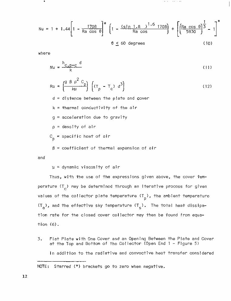
Nu = 1 + ,.44[, - Ral;Ef e]* [I - (sin ;;8co;“6 “,,) + [p5;;; ‘1’ - 1]*
8 5 60 degrees (10)
where
Nu = hc,p-c d k
Ra = (” “52 “) [tTp - TcI d3)
(11)
(12)
d = distance between the plate and cover
k = thermal conductivity of the air
g = acceleration due to gravity
p = density of air
Cp = specific heat of air
B = coefficient of thermal expansion of air
and
u = dynamic viscosity of air
Thus, with the use of the expressions given above, the cover tem-
perature (TcI may be determined through an iterative process for given
values of the collector plate temperature (Tp), the ambient temperature
CT,>, and the effective sky temperature (Ts). The total heat dissipa-
tion rate for the closed cover collector may then be found from equa-
tion (6).
3. Flat Plate with One Cover and an Opening Between the Plate and Cover at the Top and Bottom of the Collector (Open End 1 - Figure 5)
In addition to the radiative and convective heat transfer considered
NOTE : Starred (*c) brackets go to zero when negative.
12

NIGHT SKY AT T,
AIR AT Tn
WARM AIR OUT AT T,l
COOL AIR IN AT T,, /‘-
FIGURE 5. Heat Transfer Components in Open-End 1 Collector.

in the previous section, the analysis of this collector geometry is com-
plicated by the natural convection flow through the air gap between the
plate and cover producing a draft or “chimney effect” as shown in Figure
5. Air at ambient temperature enters the gap, is heated by the warm
col lector plate, which produces a buoyant force, thus causing the air to
rise until it exits at the top.
If it is assumed that the flow is laminar over the entire length of
the plate and that the gap is small compared to the plate length, then
it seems reasonable to assume that the velocity and temperature profiles
are fully developed at the exit. Additional ly, if the prof i les are con-
sidered to be essentially constant the momentum and energy
equations may be solved exactly for the velocity and temperature pro-
files at the exit.
With a knowledge of these relationships, a mass flow rate and a
bu I k air temperature at the ex it may be calculated from which the energy
absorbed by the air may be found. Lett i ng “x” be the direction along
the plate, the governing equations for two dimensional, incompressible
flow are as fol lows:
a) Continuity Equation
au+&=, ax ay
b) X-Momentum Equation
au au P u x + v F ( I
ap = -- &I
ax - PS, + 1J ay2
(13)
(14)
and c) Energy Equation
aT aT a% uax+Vay=C1-
aY2 (151
14

where
X = direction along collector plate
Y = direction across the air gap
U = velocity in the x direction
V = velocity in the y direction
PgX = body force in x direction
P = air density’
ap ax = pressure gradient in the x direction
9, = acceleration of gravity in the x direction
1-I = viscosity (assumed constant)
and
a = molecular thermal diffusivity
Solution of these equations subject to the stated assumptions (see
Appendix yields the following results:
Velocity Prof i le
3 u, = g zi; ’ (Tc - ToI 2 - &
a [ 1 + (Tp - TaI [+ - <]
where
v = kinematic viscosity
Temperature Prof i le
T cl1 = 5 [Tc - TP1 +T P
(16)
(17)
1 The density (p) in the body force term is considered to vary with tem- perature while the density appearing elsewhere is assumed to be constant.
15

Bulk Fluid Temperature (T,,) at Exit
T01 =
$T +Tc12- T,(T + Tc) -&T Tc
T P
- 2 Ta + Tc
Mass Flow Through Air Gap Ci,)
ril, = Pa W d3 g sin 0
R T01 (T
24vTa p - 2 Ta + Tc)
(‘8)
(‘9)
where
Pa = atmospheric pressure
W = collector width
R = gas constant for air
The net convective heat transfer from the collector plate to the
air flowing through the gap (Qgap 1) is given by:
Q gap ’
= (r+CpHTo - Ta)
and
qgap 1 c = $ (r;llHCpHT
0 - Ta)
(WI (20)
(W/m2)(unit areaI(21)
where
AC = col I ector area
The total heat loss (qtot 3 1 from the open ended 1 collector is
given by:
qtot 3 = qgap 1 + qr,c-s + qc,c-s (W/m21 (22)
where the heat transfer components from the cover to the sky are as given
for the closed cover geometry. Again the solution is dependent on a
knowledge of the cover temperature (Tc) which may be found from the ap-
propriate energy balance as before. That is,
16

q r,p-c + qc,p-c = qr,c-s + qC,C-S
where
9 v-c = radiation from plate to cover
a(T4 - T;I =
$+$- 1 (W/m21
P c
9 r,c-s = radiation from cover to sky
= E c o(Tz - Tz) (W/m21
(23)
(24)
9 c,c-s = convection from cover to surrounding air
= (5.7 + 3.8 VI CT - Ta) C
(W/m21
and
(26)
9 c,p-c = convection from plate to cover
Determination of the convective heat transfer from the collector
plate to the cover poses a problem due to the difficulty of obtaining a
solution of the governing equations all along the collector length. How-
ever the flow is assumed fully developed at the exit (v = 0) and in this
region heat is transferred from the collector plate to the cover by pure
conduction through the air gap.
Since there is no know ledge of the entrance region flow character-
istics, it is assumed that the heat convected from the plate to the cover
is of the same order of magnitude all along the length of the collector
as it is at the exit. This simplification yields the following result:
q c,p-c = $ (T
P - Tc) (W/m21 (27)
The cover temperature (.Tc) must agaln be found through an i terai- ive
process using the expressions given above and the total heat dissipat ion
17
(251

rate for the open ended (1) collector geometry may then be found from
equation (22).
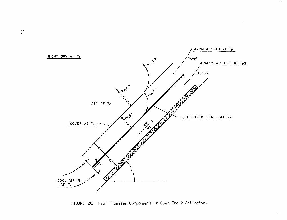
4. Flat Plate with One Cover and an Opening Between the Collector Plate and Cover and Between the Plate and Back Insulation at the Top and Bottom of the Collector (Open End 2 - Figure 6)
Analysis of the open-ended 2 collector scheme is essentially as
given for open end 1 collector with the addition of the free convection
flow on the bottom side of the collector plate. That is,
qtOt 4 = qtOt 3 + qgap 2 (28)
where
qtot 4 = total heat transfer rate for geometry (4)
and
qw 2 = convective heat dissipated through the air gap
below the collector plate
Fully developed flow at the exit is again assumed. Letting “xl’ be
the direction along the plate and “y” across the air gap, the governing
equations are identical to equations (131, (141, and (15).
Solution to these equations subject to the appropriate boundary
conditions yields the following results
2 - d2 Y) (29)
T =T 92 P
To2 = Tp
(30)
(31)
ri2 = PdzWgsin0
12 Rv (32)
where subscript 2 refers to the lower ai r gap. Thus, qgap 2 becomes
18

// WARM AIR OUT AT T,,l
NIGHT SKY AT Ts
AIR AT Tn
WARM AIR OUT AT To2
COLLECTOR PLATE AT Tp
FIGURE 6, Heat Transfer Components in Open-End 2 Collector.

(33)
and the tota I heat transferred for geometry (4) can be found from equa-
tion (28).
20

RESULTS OF COOLING MIDE ANALYSIS
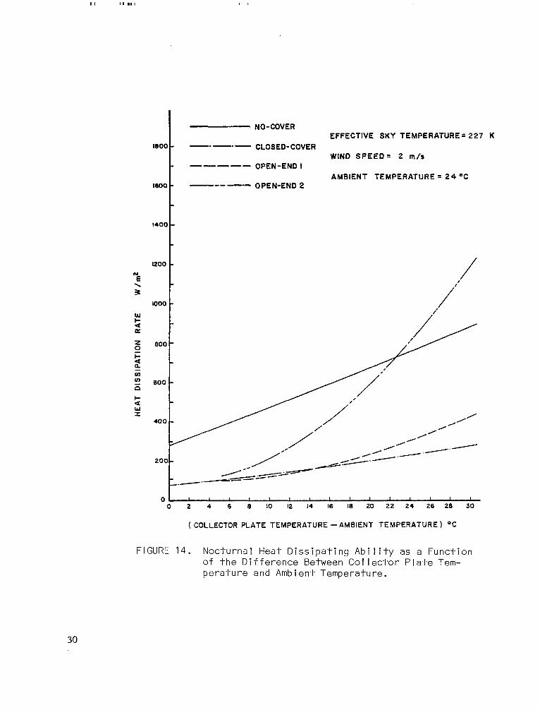
Results of the heat transfer analyses explained in the previous
sections are shown in Figures 7 through 15. Property values and col-
lector dimensions used in the analysis are shown in Table I. Note that
the AT’s are generated by hoIdi,ng the ambient temperature constant at
24OC and increasing the plate temperature. Curves for the open ended
collector geometries terminate at low AT’s under certain conditions due
to a breakdown in the free convection analysis. This occurs if the cover
temperature drops below ambient temperature to the point that the fol-
lowing condition is satisfied:
T P
- 2Ta + Tc = 0
At this combination of temperatures, m, becomes zero and the flow would
theoretical ly reverse direction. As noted, this condition is only satis-
fied at relatively low AT’s and is considered out of the range of in-
terest from a practical heat pump operation standpoint.
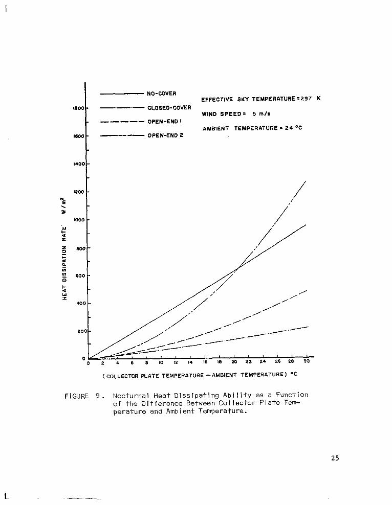
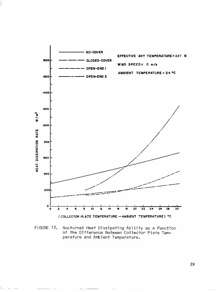
As can be seen from the graphs, the no-cover co/ lector geometry is
a superior heat dissipator under nearly all the conditions shown. The
open end 2 geometry does out-perform the no-cover collector during com-
binations of low wind speeds, high effective sky temperatures, and fairly
high ATIs. The heat rejection ability of the open end 1 and closed
cover collector geometry is limited except at high temperature differ-
ences.
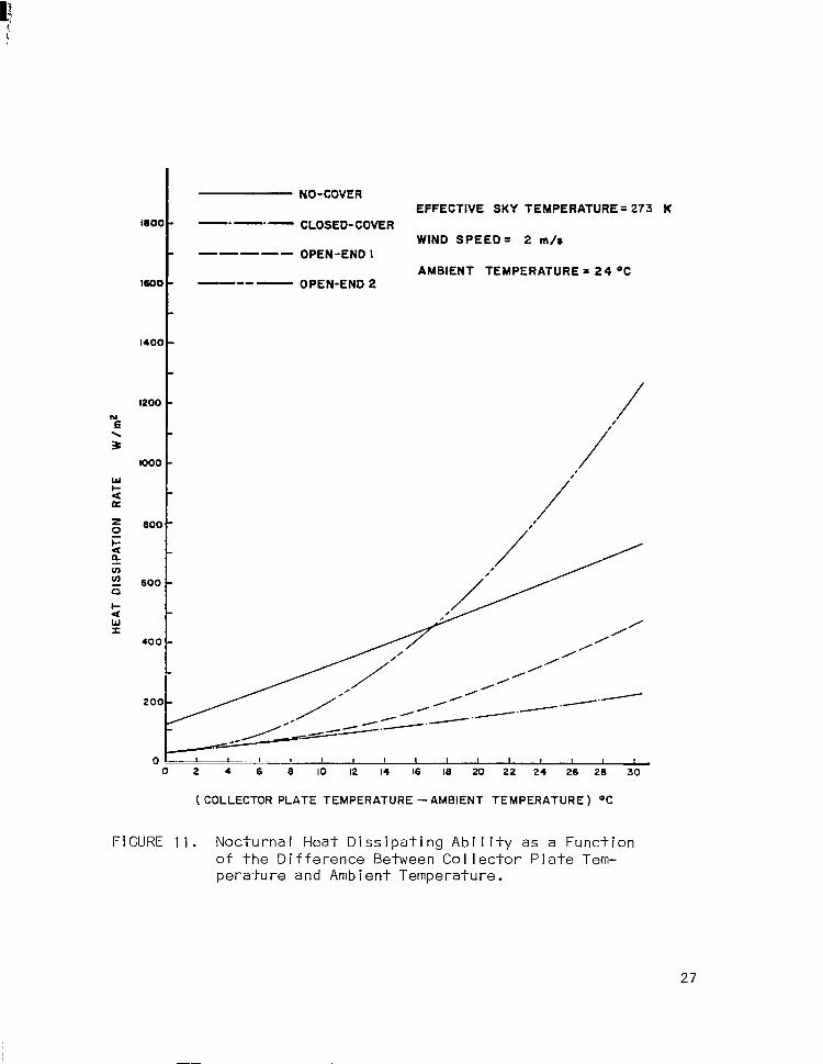
The effect of wind speed and the effective sky temperature on the
heat dissipation rate at a AT of 15OC is shown in Figures 16 and 17, re-
spectively. Note that only the no-cover geometry is significantly sen-
sitive to either variable. However, since the effect of wind direction
21
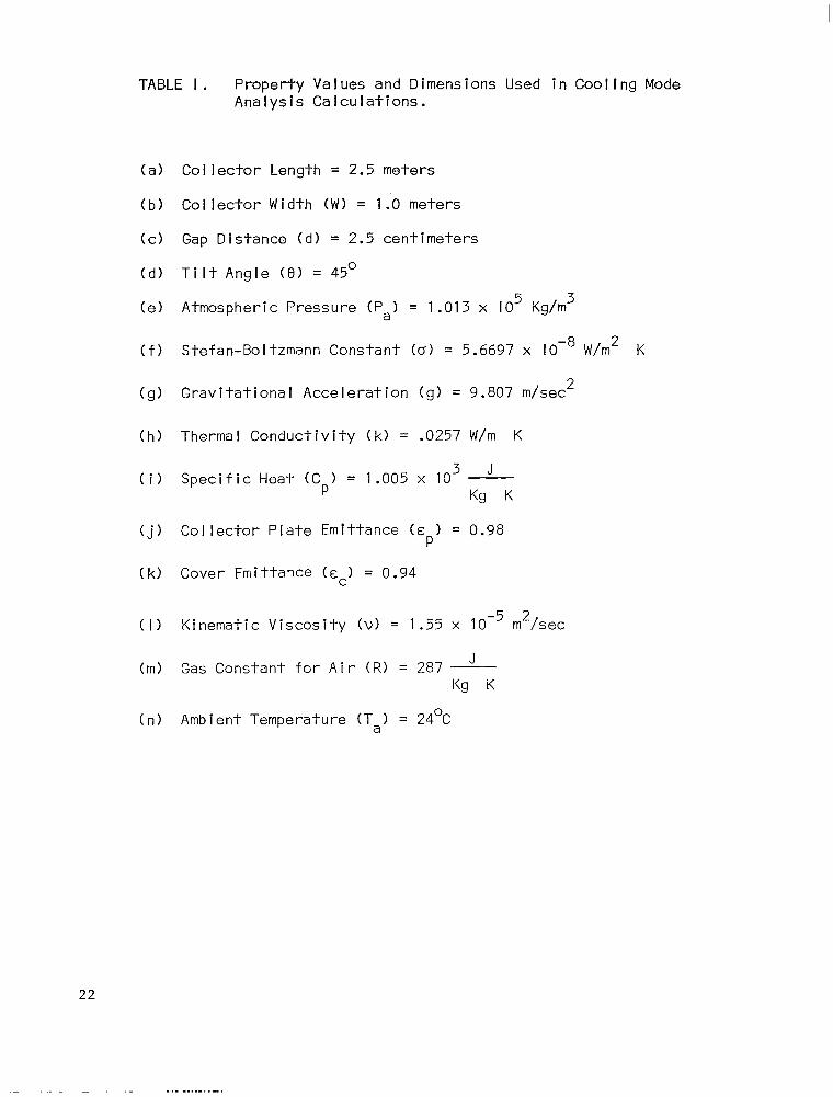
TABLE I. Property Values and Dimensions Used in Cooling Mode Analysis Calculations.
(a) Collector Length = 2.5 meters
(b) Collector Width (WI = 1.0 meters
(c) Gap Distance (d1 = 2.5 centimeters
(d) Tilt Angle (8) = 45O
(e) Atmospheric Pressure (PaI = 1.013 x IO5 Kg/m3
(f) Stefan-Boltzmann Constant (a) = 5.6697 x lOa W/m2 K
(g) Gravitational Acceleration (g) = 9.807 m/sec2
(h) Thermal Conductivity (k) = .0257 W/m K
(i) Specific Heat (Cp) = 1.005 x lo3 J Kg K
Cj) Collector Plate Emittance (~~1 = 0.98
(k) Cover Emittance (cc) = 0.94
(1) Kinematic Viscosity (VI = 1.55 x 10m5 m2/sec
(m) Gas Constant for Air (RI = 287 J Kg K
(n) Ambient Temperature (T,) = 24OC
22
_. _ _... -. . . . .

1800 -
IWO -
1400 -
1200 -
% . 3
IO00 - l&l
2
$ 000 -
5 a. Ls v) E 600 -
5 Y
400 -
200 -
NO-COVER EFFECTIVE SKY TEMPERATURE = 297 K
-.- -- CLOSED-COVER WIND SPEED= 0 m/s
----- OPEN-END I
AMBIENT TEMPERATURE = 24 *C P-m - OPEN-END 2
( COLLECTOR PLATE TEMPERATURE -AMBIENT TEMPERATURE ) ‘%
FIGURE 7. Nocturnal Heat Dissipating Ability as a Function of the Difference Between Collector Plate Tem- perature and Ambient Temperature.
23

1800 -
I600 -
1400 -
1200 -
%
2
IO00 -
e a K
g wo-
I= a a
v, rn
z 600 -
G
k! 400 -
NO-COVER EFFECTIVE SKY TEMPERATURE= 297 K
-.m *- CLOSED-COVER WIND SPEED= 2 m/s
----- OPEN-END I AMBIENT TEMPERATURE = 24 “C
--- - OPEN-END 2
0 2 4 6 9 10 12 14 I6 I8 20 22 24 26 28 30
( COLLECTOR PLATE TEMPERATURE -AMBIENT TEMPERATURE ) ‘c
FIGURE 8. Nocturnal Heat Dissipating Ability as a Function of the Difference Between Collector Plate Tem- perature and Ambient Temperature.
24
O-
O-
IO -
o-
IO -
)O -
IO -
10 -
oo-
OU 0
F I GURE
NO-COVER EFFECTIVE SKY TEMPERATURE = 297 K
-. -.- CLOSED-COVER WIND SPEED= 5 m/r
----- OPEN-END I AMBIENT TEMPERATURE = 24 “C
e--- OPEN-END 2
/
( COLLECTOR PLATE TEMPERATURE -AMBIENT TEMPERATURE 1 ‘C
9. Nocturnal Heat Dissipating Ability as a Function of the Difference Between Collector Plate Tem- perature and Ambient Temperature.
25
L

I8OC
16000
1400
1200
% . 3
ia00
)-
I-
t-
400 -
200 -
NO-COVER EFFECTIVE SKY TEMPERATURE= 273 K
-.- -- CLOSED-COVER WIND SPEED= 0 m/s
----- OPEN-END I AMBIENT TEMPERATURE = 24 OC
--- - OPEN-END 2
01 I I I 1 1 I I ! 1 I I 8 1 , 0 2 4 6 8 IO I2 14 16 16 20 22 24 26 26 30
( COLLECTOR PLATE TEMPERATURE -AMBIENT TEMPERATURE ) OC
FIGURE 10. Nocturnal Heat Dissipating Ability as a Function of the Difference Between Collector Plate Tem- perature and Ambient Temperature.
26
NO-COVER EFFECTIVE SKY TEMPERATURE = 273 K
1800 - -.- -- CLOSED-COVER WIND SPEED= 2 m/s
- ----- OPEN-END I AMBIENT TEMPERATURE = 24 OC
1600 - ---- OPEN-END 2
1400 -
1200 -
% / I’
.
3
1000 - /
E
I’
2 z
/ a00 -
F 4 a ii v) z 600 -
2 it /
/ 400 - /
/ I
I I
I
0 I I I I I I # I 9 I 0 2 4 6 8
L--.-l II, IO 12 16 I6 20 22 24 26 26 30
1 COLLECTOR PLATE TEMPERATURE -AMBIENT TEMPERATURE) “‘2
FIGURE 11. Nocturnal Heat Dissipating Ability as a Function of the Difference Between Collector Plate Tem- perature and Ambient Temperature.
27

16OC
I6OC
MOC
1200
% . 3
IO00
i K
B 8OC F 2 v,
)-
I-
l-
-
, -
I’
UY E
600 -
z ii
400 -
NO-COVER EFFECTIVE SKY TEMPERATURE= 273 K
-.- .- CLOSED-COVER WIND SPEED= 5 m/r
----- OPEN-END I AMBIENT TEMPERATURE = 24 OC
Y-e P OPEN-END 2
01 1 , , I I , I I I 0 2 4 6 6 IO I?. 14 16 16 20 22 24 26 26 30
( COLLECTOR PLATE TEMPERATURE -AMBIENT TEMPERATURE) ‘C
FIGURE 12. Nocturnal Heat Dissipating Ability as a Function of the Difference Between Collector Plate Tem- perature and Ambient Temperature.
28
1.00 -
1600 -
1400 -
IZOO -
% . 3
z a00 -
t=
2
v, 03 600 - s
NO-COVER
-.- *- CLOSED-COVER
----- OPEN-END I
--- - OPEN-END 2
EFFECTIVE SKY TEMPERATURE= 227 ‘K
WIND SPEED= 0 m/s
AMBIENT TEMPERATURE = 24 %
0 2 4 6 8 IO I2 14 I6 18 20 22 24 26 26 30
( COLLECTOR PLATE TEMPERATURE -AMBIENT TEMPERATURE ) “2
FIGURE 13. Nocturnal Heat Dissipating Ability as a Function of the Difference Between Collector Plate Tem- perature and Ambient Temperature.
29
1600 -
I600 -
1400 -
1200 -
% . 3
IO00 -
5 800 -
F 4 0. v, v) 600 - z
NO-COVER EFFECTIVE SKY TEMPERATURE= 227 K
m.- .- CLOSED-COVER WIND SPEED= 2 m/s
----- OPEN-END I AMBIENT TEMPERATURE = 24 %
-se - OPEN-END 2
0 I I I 1 I I I I I I I I 9 I 0 2 4 6 8 IO 12 14 16 I8 20 22 24 26 26 30
( COLLECTOR PLATE TEMPERATURE -AMBIENT TEMPERATURE ) ‘C
FIGURE 14. Nocturnal Heat Dissipating Ability as a Function of the Difference Between Collector Plate Tem- perature and Ambient Temperature.
30

I
I800 I- -.- -- CLOSED-COVER
----- OPEN-END I
1600 -B-w OPEN-END 2
1400
1200
“E . 3
loo0
F s
E 800
F 2 ;i OY E 600
5
!i 400
NO-COVER EFFECTIVE SKY TEMPERATURE= 227 ‘K
WIND SPEED= 5 m/r
AMBIENT TEMPERATURE = 24 OC
0 z 4 6 6 IO I2 14 I6 I8 20 22 24 26 28 30
( COLLECTOR PLATE TEMPERATURE -AMBIENT TEMPERATURE) OC
FIGURE 15. Nocturnal Heat Dissipating Ability as a Function of the Difference Between Collector Plate Tem- perature and Ambient Temperature.
Ill - -.
31
-

400 :
1 : 2oc
0 229 237 245 253 261 269 277 265
EFFECTIVE SKY TEMPERATURE K
600 -
NO-COVER AMBIENT TEMPERATURE = 24 OC
-.-.- CLOSED-COVER PLATE TEMR-AMBIENT TEMF? = l5OC
--- - OPEN-END I
--- - OPEN-END 2
------
V=5 m/s
L. -. V=O m/a -.-.__.;-A
V=5 m/r .-=z
FIGURE 1’6. Nocturnal Heat Dissipating Ability as a Function of Effective Sky Temperature.
32

14oc
12oc
IOOC
601
401
20
0
) -
I -
I-
I-
D-
o=
c
Op
NO-COVER AMBIENT TEMPERATURE = 24 * C
-. -.- CLOSED-COVER PLATE TEMR -AMBIENT TEMP. = 15 “C
--- - OPEN-END I
--a - OPEN-END 2
r2zox------------------- .-.-.- .-.-
273%-.-‘-‘-. .- .-.-
-Eggs’-’
0 I 2 3 4 5 6 7 6 9 IO II I2 I3 14 I5
WIND SPEED m/s
FIGURE 17. Nocturnal Heat Dissipating Ability as a Function of Wind Speed.
33
was not included in the analysis, the results shown above should be re-
garded with care. The free convection heat transfer component in the
open-ended collector geometries would probably be enhanced by wind com-
ing from most directions, although this relationship is not clearly
estab I ished.
The selection of a particular collector geometry for use in a
specific installation is influenced by the heating as well as cooling
mode collector performance. Of course, the desired outcome is to utilize
the collector system that will provide a high temperature heat source in
winter and a low temperature heat sink in summer. Consideration must
also be given to the demand requirements on the heat pump itself and the
relative magnitude of loads as determined by the geographical location.
For example, a structure in the North would have a relatively greater
heating load and smaller cooling load than its counterpart in more
southern regions. Additional ly, heating mode collector efficiency is
genera I I y poorer in the North. Thus, an efficient winter absorber that
may not necessarily be a good summer dissipator may be more cost effect-
ive in northern locations. In the South, on the other hand, a collector
with no cover may provide adequate winter performance, while optimizing
summer heat dissipating ability. These general conclusions are obvious-
ly affected by yearly heat pump operating costs versus initial collector
cost considerations, and the choice of the most suitable option becomes
quite involved and dependent on the characteristics of the specific ap-
plication.
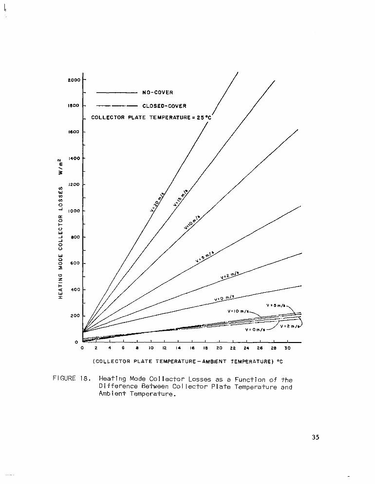
Heating mode performance for the no-cover and closed-cover collec-
tors is shown in Figure 18 for a variety of operating conditions. The
34
1000
1600
“E
1400
. 3
1200 cn w VJ cn 0 -I 1000
E l- o w -I 000
0’ 0
W z
F a 400
ii
200
0 0 2 4 6 0 IO I2 I4 I6 I6 20 22 24 26 26 30
(COLLECTOR PLATE TEMPERATURE -AMBIENT TEMPERATURE) ‘%
FIGURE 18. Heating Mode Collector Losses as a Function of the Difference Between Collector Plate Temperature and Ambient Temperature.
35

collector heat loss is plotted as a function of the difference between
the col lector plate temperature and the ambient temperature for various
wind speeds. Note that for this case the AT is generated by holding the
collector plate temperature constant while the ambient temperature is
decreased. A collector p ate temperature of 25’C is considered in com-
bination with wind speeds of 0, 2, 5, 10, 15, and 20 meters per second.
Details of the heat trans fer analysis for the heating mode operation are
identical to the cooling mode analysis with the exception of the value
of the effective sky temperature. Duffie and Beckman’ suggest the use
of the following relation given by Swinbeck (1963) for clear days:
TS = 0.0552 Tal*’
where Ts and Ta are in degrees Kelvin.
With the aid of the cooling and heating mode collector
curves shown above, it is felt that the selection of the col
metry most suitable for a specific application becomes clear
performance
I ector geo-
er.
A brief outline of a simplified procedure for determination of the
relative performance of the various collector options is given below. A
mean daily solar insolation value for January is taken from U. S. Weather
Bureau climatological data for Greensboro, North Carolina. It is as-
sumed that the cooling load is equal to the heating load in one case and
then equal to one-half the heating load in the second. The genera I ap-
preach taken s to size the collector area for the heat ing load and then
determine the AT required to satisfy the heat dissipati on rate necessary
to meet the cooling load. Detai Is of the analysis follow:
1 See Reference 1, pg. 76.
36

Assumptions
(a> Solar ins0
(b1 Solar inso
lation on a horizontal surface = 2.32 KWH/m2-day
lation on a surface tilted 45O = 3.55 KWH/m2-day
(c> Heating load = 322 KWH/day
(d) Can collect heat over seven hour period
(e) Wind speed for heating and cooling modes = 2 m/set
(f) Effective sky temperature for the cooling mode = 273 K
(g> The solar collector is operated in the heating mode at a AT of 15OC.
(h) Can dissipate heat over eight hour period
Calculations
(a) Heating load
First determine the average solar insolation for the seven
hour heat collecting period. Thus,
Average solar heat available = 3.55/7 = 507 W/m2
The heat loss under the conditions stated above can be found
from Figure 41 for the no-cover and closed-cover geometries.
No cover heat loss = 335 W/m2
Closed cover heat loss = 110 W/m2
The heat collection ability of the two geometries is then found as
fol lows:
No cover = 507 - 355 = 172 W/m2
Closed cover = 507 - 110 = 397 W/m2
Thus, the total collector area required is
No cover area = 32,200/(172)(7) = 267 m2
Closed cover area = 32,200/(397)(7) = 116 m2
37

(b) Cooling Load
(i> Case I - Cooling load = heat i ng load = 322 KWH/day
For eight hour night must dissipate 332/8 = 40.2 KWH/hr
or
No-cover average heat dissipation rate =
40,200/267 = 151 W/m2
Closed-cover average heat dissipation rate =
40,200/116 = 347 W/m2
From Figure 34 the AT’s required for the heat dissipation rates
above are as follows:
No-cover - 1 OC AT
Closed-cover - off the graph
Closed-cover to open-end 1 = 25’C AT
Closed-cover to open-end 2 - 14.5OC AT
Note that is is assumed the no-cover collector remains as is, while
the closed cover collector may be changed to either of the other
geometries for cooling mode oepration.
(ii) Case II - Cooling load = one-half heating load =
161 KWH/day
The average heat dissipation rates are as follows:
No-cover col lector = 75 W/m2
Closed-cover collector = 173 W/m2
Again, from Figure 34 the AT’s are as follows:
No-cover - radiation alone is sufficient at O°C AT
Closed-cover - 23’C AT
Closed-cover to open-end 1 - 16OC AT
Closed-cover to open-end 2 - 10°C AT
38
hea
rea
ti
Ii
For optimum performance of the heat pump a small AT for both the
ng and cooling modes is required. Both these objectives may be
zed by increasing the collector area. However, this design option
obviously leads to higher initial costs and the trade-off becomes one of
increased initial cost versus higher operati.ng costs. The matter is
further complicated by the various collector alternatives, as can be
seen even from the simplified analysis shown above.
While the selection of the most cost - effective collector alter-
native is a complex matter, the results of the preceding analysis do sug-
gest the following general conclusions:
(11 It seems probable that for many applications the open-end
2 geometry presents a feasible means of utilizing the
collector system as a heat sink without sacrificing heat-
ing mode performance or substantially adding to initial
costs .
(2) Due to the severe heating mode losses suffered at even
moderate wind speeds, it is felt that the no-cover col-
be practical only in applications where the
exceeds the heating load and where h igh
lar insolation are available. This alterna-
lector would
cooling load
levels of so
tive would a
ing mode toe
(3) The open-end
Iso seem the better choice if a lower heat-
fficient of performance is acceptable.
1 and closed-cover collector geometries are
unsuitable for use as heat dissipators.
In closing, it should be recognized that the results derived above
are approximate and their principal importance is in presenting a per-
formance comparison of the collector geometries considered. Absolute
39

values for the heat dissipation rates of the collectors under actua I
operat i ng cond itions must obviously be derived by experimental means.
However, the conclusions drawn above do indicate that utilization of the
collector system on a year-round basis is a practical means of justify-
ing the high initial costs of a solar energy ins-l-al lation, particularly
if the heat pump concept is employed.
40

CONCLUSION
The results of the present cooling mode analysis coupled with
previously reported heat mode performance suggest that the solar assisted
heat pump system is a viable alternative to the more conventional means
of solar energy utilization. Thus, even though economic implications
have not been fully explored, it is felt that construction of a larger
scale prototype is certainly justified. The concluding remarks given
here will therefore be limited to suggestions with regard to design con-
siderations of such a system.
Since the response of the refrigerant flow control system is con-
sidered the most critical element in optimizing the performance of a
solar assisted heat pump, it is recommended that externally driven
compressors be specified for installat on in a multiple compressor
arrangement. This would allow maximum flexibility of control of the
compressor displacement without requir ng extensive modifications.
Furthermore, the fine adjustment capability thus achieved
the establishment of optimum flow rates for various opera
allow for refrigerant substitutions. Additional
ting conditions
and even
externa I
pump for
of the d i
pressors
ly, most
y driven compressors are provided with a sight glass in the
monitoring the oil level, an important consideration in view
fficulties encountered in the NCSU system. The use of com-
of this type would also have the benefit of the relative ease
would permit
with which periodic inspections of the valves and piston rings could
be made.
41

In conclusion, it is hoped that the material presented in this
report wi I I stimulate sufficient interest to encourage further research
and development of solar assisted heat pumps. As noted earlier, the
NCSU system was built on a limited budget and was undertaken primarily
as a design exercise for undergraduate engineering students. Therefore,
significant performance improvement is considered possible.
42

BIBLIOGRAPHY
1. Duffie, J. A. and Beckman, W. A. So I ar Energy Therma I Processes, John Wiley and Sons, New York, 1974.
2. Hackforth, H. L. Infrared Radiation, McGraw-Hill, New York, 1960, pp. 42-45.
3. White, F. M. Viscous Fluid Fl,ow, McGraw-Hill, New York, 1974.
43

APPEND I X
OPEN-ENDED COLLECTORS HEAT TRANSFER ANALYSIS
A. Open-End 1 Co I lector
For sake of clarity, the heat transfer components involved in the
open-end 1 col lector geometry are shown in Figure 19. Treatment of the
radiation components, q w-c and qf- c-s’ and the convection components,
,
4 c, P-c and q c,c-s’ is given in the cooling analysis. Therefore, con-
sideration here is limited to the development of the natural convection
draft problem.
As mentioned in the cooling mode analysis, air at ambient tempera-
ture CT,) enters the opening at the bottom of the collector, is heated
by the warm plate and exits through the top opening. The net energy
transferred from the plate to the air (Q gap 1
> is a function of the air
mass flow rate and the bulk fluid temperature’ (To,) at the exit. That
is,
Q gap 1
=i C(T 1 p 01
- Ta) (A .l)
It is assumed that the flow is essentially incompressible and that fully
developed laminar flow exists at the exit. Thus,
u = u(y) only
and
T= T(y) only
The bulk fluid temperature is defined as:
1 Also known as mixed mean fluid temperature.

NIGHT SKY AT TX WARM AIR OUT AT To1 4
AIR AT T,
COOL AIR IN AT To /
FIGURE 19. Heat Transfer Components in Open-End 1 Collector.

d
I u(y) T(y) dy
(A.21 0
To,= d
I u(y) dy
0
and the mass flow is defined in terms of the mean fluid velocity r as
. ml = P, Agap u
where
d 1 ;=- d I
u(y) dy
0
(A.31
(A.41
and
A = dW (A.51 gap
As can be seen from the relations shown above, determination of
Q gap 1
requires the solution of the governing flow equations for the tem-
perature and velocity prof i les. The governing equations are as follow:
(a1 Continuity Equation
?i+&=, aY
(b) X-Momentum Equation
ap a2u p ' I &+,au =
ax w I -ax -m,+lJ-- aY2
(~1 Energy Equation
(A.61
(A.71
(A.81
Since the flow is generated by thermal effects, the equations are
coupled and the solution for the velocity profile requires knowledge of
46

the temperature distribution. Consider the ene.rgy equation. If it as-
sumed that the temperature profile is essentially constant in the region
near the exit2 the analysis is greatly simplified and the energy equa-
tion reduces to an ordinary differential equation. The boundary condi-
tions are constant wall temperatures, Tp at the plate and Tc at the cov-
er. Thus, aT/ax = 0, v = 0 for fully developed flow and constant pro-
files and
T= Tp @ y = 0
T = Tc @ y = d
Therefore,
integrating
and
but
and
a2T=, aY2
aT ay= cl
T = Cly + C2
T=TP@y=o
T = Tc @ y = d
Thus,
T 241
= z (T C -TP) +T P
(A .9)
(A.101
(A .11)
(A.121
2 See Reference 3, pp. 114-117.
47

Note the resulting temperature profile is linear in y. Next con-
sider the continuity and x-momentum equations. Since the flow is fully
developed (v = 01, the continuity equation yields the following result:
Thus, the x-momentum equation becomes
(A.131
(A.141
where - p g X
=-the body force in the x-direction.
The pressure force term under these conditions is the external "hy-
drostatic" pressure gradient due to changes in elevation. Thus,
ap ax= - 'a gx
,A.151
The density difference (pa - p) may be approximated in terms of the
volume coefficient of expansion, as follows:
I av B'v F i I
lv-'a
P =5-i--T
a
or
f3= Pa - P
p(T - Ta)
(A.171
(A.181
Thus,
(P a - p) = p(T - T,)B (A.191
Substitution of equation (A.171 into equation (A.141 and dividing by p
yields,
48

2 0 = g, B(T - Ta) + v q
w (A .20)
But, g, = g sin 0 for the geometry given and T = z (Tc - Tp) from the
equation (A. 10). Thus, after rearranging, the x-momentum equation be-
comes
C -Tp)+T -Ta
P I
The no slip boundary conditions are
u=O@y=O
u=O@y=d
(A.211
(A.221
Integrating equation (2.19) twice yields
89 2
u1 = - zin ’ - Tp) + $ (T (A.231 P - Ta) 1 + clY + c2
Application of the boundary conditions results in the following
cl = 6 q fn ’ C
- Tp) + 4 (Tp - Ta) I
(A.241
and
c2 = 0
So the velocity profile becomes
u1 = ’ ’ zin ’ ( (Tc - Tp) (+ - 2) + (T (A.251 p
If the air is considered an ideal gas the volume coefficient of expansion
may be expressed as follows
‘a
B.j& a
from equation (A.161 and
49
I I

I
from the ideal gas law. So
T Ty 1
T
B=T-T = T- l
a Ta (< - ‘1
or
a (A .26)
With a knowledge of the approximate velocity and temperature pro-
files derived above the solution for the bulk fluid temperature and the
mass flow rate may be carried out by substituting the appropriate func-
tions in equations (A.21, (A.31, and (A.41. Performing the necessary
integrations results in the fol lowing expressions
T = & (T + Tc12 - T,(T + TcI +T Tc
01 T P
- 2 Ta + Tc
; = 1
d2Bg sin 0 (T 24 v P
- 2 Ta + Tc) (A .28)
(A .27)
and
. p, W d3 B g sin 8
ml = 24 V Ta (T - 2 Ta + Tc) (A .zg)
P
where p, is the density evaluated at the bulk fluid temperature which
can be expressed with the use of the perfect gas law as follows
‘a PO = -
R T01 (A .30)
where Pa is the atmospheric pressure, assumed constant. Thus, after sub-
stituting for B from equation (A.261, the flow rate becomes
50

. Pa W d3 g sin 8
ml = R To1 24 v Ta (Tp - ’ Ta ’ Tc) (A.311
and the net energy absorbed by the air in fIowi,ng through the collector
is given by equation (A.1). For a collector of characteristic dimen-
sions, the average heat transferred per unit area may be found by divid-
ing by the collector area
qgap . Thus
= j+ (r;l,,tCp)(To 1 c 1
refers to the gap Note that the subscript 1
- Ta) (A.321
above the collector plate.
B. Open-End 2 Col lector
As in the previous section, the discussion here is limited to the
convection problem through the air gap. The principal heat transfer com-
ponents are shown in Figure 20. Since it is assumed that the collector
plate temperature is held constant, the heat transfer components above
the plate are unaffected by the convection through the lower air gap.
Therefore, consideration here is given only to the development of the
free convection below the collector plate. Again it is assumed the f
is fully developed, laminar and essentially incompressible in the reg
near the exit. The constant profile assumption is also required for
slmpl i.f Ication. Thus, the governing equations reduce to the followin
(a) Continuity
9
2%=(-J ax
(b) X-Momentum
a2u f3 g -= ay2
zin e lT - T) a
ow
on
(A .33)
(A ,341
51
NIGHT SKY AT Ts
WARM AIR OUT AT Toi
WARM AIR OUT AT To2
COLLECTOR PLATE AT Tp
COVER AT Tc
FIGURE 20. Heat Transfer Components in Open-End 2 Col I ector.

(c> Energy Equation
?Lo
w2 (A.351
Note the equations are coupled as before, and the solution first requires
determination of the temperature prof i le. The appropriate boundary con-
ditions are as follows
T= TP @ y = O
Thus
and
cl=0 , C2 = T P
so
T =T 92 P
(A.371
Note the temperature is constant all across the air gap and the
bulk fluid temperature T,, is equa I to the plate temperature of
(A.391
“L
T02 = Tp
ion (A.371 into the x-momentum equat Subst itution of equat
fol lowing
aT ~‘0 @y=d2
T 92
= Cly + c2
(A.361
ion yields the
a2u f3 9 -= aY2
sin ’ [Ta - Tp] V
(A.401
But
so
53

a2u -= g sin 8
ay2 V [ 1 L
’ -T a
and after integrating
y2+c1 Y +c2
(A.41 1
(A.421
The no slip boundary conditions are
u=O@y=O
u=0@y=d2
Thus
- d2 Y) (A.431
Substitution of these profiles into the expressions for u and i yields
- u2 = (A.441
(A.451
. PadsWgsine m2 =
12 R v (A .46)
Thus, the net energy absorbed by the air flowing through the lower
gap, on a unit collector area basis, is given by
dz Pa C W g sin 8
qgap 2 = AC 12 R v (A.471
54
1. Report No. 2. Government Accession No. 3. Recipient’s Catalog No.
NASA CR-3111 4. Title and Subtitle 5. Report Date
An Analytical Investigation of the Performance of Solar March 1979
Collectors as Nighttime Heat Radiators in Airconditioning 6. Performing Organization Code
Cycles 7. Author(s) 8. Performing Orgamzation Report No.
Clay B. Jones and Frederick 0. Smetana
9. Performing Organization Name and Address
North Carolina Science and Technology Research Center, P.O. Box 12235, Research Triangle Park, NC 27709
2. Sponsoring Agency Name and Address
National Aeronautics and Space Administration Washington, DC 20546
5. Supplementary Notes
Langley Technical Monitor: John Samos
_ 10. Work Unit No.
11, Contract or Grant No.
Outgrowth of NASl-14208 13. Type of Report and Period Covered
6. Abstract
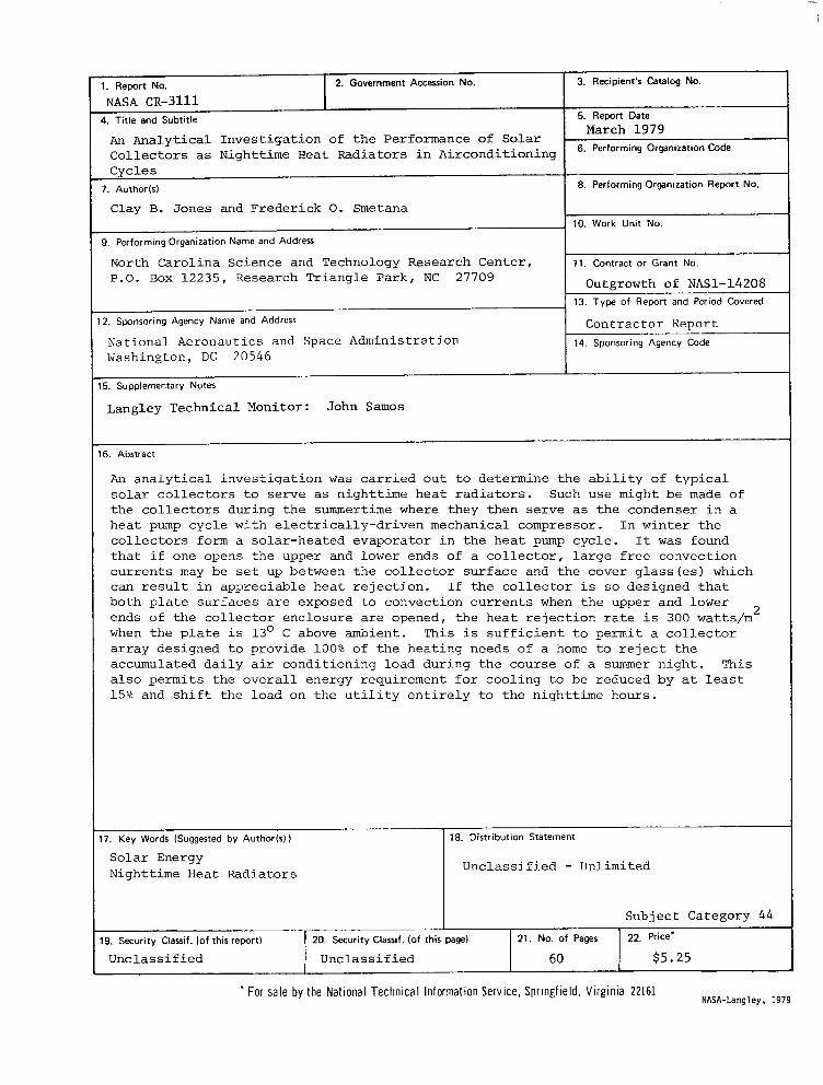
An analytical investigation was carried out to determine the ability of typical solar collectors to serve as nighttime heat radiators. Such use might be made of the collectors during the summertime where they then serve as the condenser in a heat pump cycle with electrically-driven mechanical compressor. In winter the collectors form a solar-heated evaporator in the heat pump cycle. It was found that if one opens the upper and lower ends of a collector, large free convection currents may be set up between the collector surface and the cover glass(es) which can result in appreciable heat rejection. If the collector is so designed that both plate surfaces are exposed to convection currents when the upper and lower ends of the collector enclosure are opened, the heat rejection rate is 300 watts/m2 when the plate is 13O C above ambient. This is sufficient to permit a collector array designed to provide 100% of the heating needs of a home to reject the accumulated daily air conditioning load during the course of a summer night. This also permits the overall energy requirement for cooling to be reduced by at least 15% and shift the load on the utility entirely to the nighttime hours.
17. Key Words (Suggested by Author(s) ) 18. Distribution Statement
Solar Energy Nighttime Heat Radiators Unclassified - Unlimited
19. Security Classif. (of this report1
Unclassified 20. Security Classif. (of this page)
Unclassified
Subject Category 44
21. No. of Pages 22. Price‘
60 $5.25
l For sale by the National Technical information Service, Springfield. Virginia 22161 NASA-Langley, 1979