an analysis of double exposure lithography...
TRANSCRIPT
An analysis of double exposure lithography options
Saul Leea , Je rey Byersb, Kane Jena , Paul Zimmermanb, Bryan Riceb, Nicholas J. Turroc, andC. Grant Willsona
aDepartment of Chemical Engineering, The University of Texas at Austin, Austin, Texas, USA;bSEMATECH, 2706 Montopolis Drive, Austin, Texas, USA;
cDepartment of Chemistry, Columbia University, New York, New York, USA
ABSTRACT
The current optical photolithography technology is approaching the physical barrier to the minimum achievablefeature size. To produce smaller devices, new resolution enhancement technologies must be developed. Doubleexposure lithography has shown promise as potential pathway that is attractive because it is much cheaper thandouble patterning lithography and it can be deployed on existing imaging tools. However, this technology is notpossible without the development of new materials with nonlinear response to exposure dose. The performanceof existing materials such as reversible contrast enhancement layers (rCELs) and theoretical materials such as in-termediate state two-photon (ISTP) and optical threshold layer (OTL) materials in double exposure applicationswas investigated through computer simulation. All three materials yielded process windows in double exposuremode. OTL materials showed the largest process window (DOF 0.137 µm, EL 5.06 %). ISTP materials had thenext largest process window (DOF 0.124 µm, EL 3.22 %) followed by the rCEL (0.105 µm, 0.58 %). This studyis an analysis of the feasibility of using the materials in double exposure mode.
Keywords: Double Exposure Lithography, Immersion Lithography, Double Patterning Lithography, ResolutionEnhancement Techniques
1. INTRODUCTION
The current technological progression of the photolithography industry has reached a limit in the maximumachievable resolution. Resolution as determined by the half pitch critical dimension (CD) is limited by theRayleigh equation
C D =k1 · N A
, (1)
where k1 is the process aggressiveness factor, is the wavelength of the imaging tool, and N A is the numericalaperture of the imaging lens. To reduce the half pitch C D , the industry must reduce k1 or , or increase N A .The theoretical minimum value for k1 with single exposure is 0.25, but the generally accepted manufacturabilitylimit is 0.27. The current industry standard imaging tool has a wavelength of 193 nm. Future imaging tools areproposed to operate in the Extreme Ultra Violet (EUV) range with a of 13.4 nm, however, the EUV technologywill most likely not be viable until after 2013. With water immersion lithography, the maximum achievable N Ais approximately 1.35. Increasing the N A requires simultaneous development of a high index lens material alongwith high index fluids and high index resists. Without major breakthroughs in optical materials, N A will plateaunear 1.35. Given these parameters, the current C D limit is approximately 38 nm half pitch.
To enable lithography at sub 38nm half pitch, the industry will need to consider alternative resolutionenhancement technologies. Two exposure passes have been proposed as a possible resolution enhancementtechnique for existing photolithography imaging systems. A single mask with high feature density that is di cultto resolve can be split into two exposures each with lower feature density that can be easily resolved. Whencombined, the two exposures replicate the original mask.
Further author information: Send correspondence to Professor C. Grant WillsonMail: 1 University Station C0400, Austin, TX, 78712E-mail: [email protected]
Optical Microlithography XXI, edited by Harry J. Levinson, Mircea V. Dusa, Proc. of SPIE Vol. 6924, 69242A, (2008) · 0277-786X/08/$18 · doi: 10.1117/12.773030
Proc. of SPIE Vol. 6924 69242A-1

Double Patterning
1 Exposure Develop/Etch 2 Resist 2 Exposure Develop/Etch
Renove fron Chuck Reload onto ChuckRealign Wafer
Double Exposure
1 Exposure 2 Exposure Develop/Etch
Resist P::ILJIIII! i:ic:ILJJSt kWafer
1.1 Double Exposure Lithography versus Double Patterning Lithography
Double exposure lithography (DEL) and double patterning lithography (DPL) are proposed approaches to per-forming the two exposure passes. DEL is defined as a two exposure pass lithographic process that does notrequire the removal of the wafer from the exposure tool chuck between passes. DPL is defined as a two expo-sure pass lithographic process that requires a chemical development of the photoresist layers and possibly anintermediate etch step. The DPL processing approaches will require the removal of the wafer from the exposuretool chuck and loss of overlay registration. DEL and DPL processes are illustrated in Figure 1. The benefits of
Figure 1. Comparison of the double patterning lithography(development/etch scheming shown) and double exposurelithography processes.
DEL and DPL principally include the ability to use existing exposure tools to print technology nodes below theN A limit for single exposure processes. This could mean a lower cost of ownership as these techniques can inprinciple be deployed without costly capital investment. However, the two exposure passes require doubling thenumber of masks and reduced throughput due to increased processing time. The process time is dramaticallyincreased in the DPL process because of the additional process steps compared to the DEL process. In addition,the removal of the wafer from the wafer chuck between exposures poses severe overlay issues that may be di cultto overcome, especially at the CDs where this technology will be implemented. The DEL process only introducesan additional exposure pass, and since the wafer is not removed from the imaging tool between exposures, theoverlay issues are minimized. The reduced cost of ownership of DEL suggests that it would be the preferredtechnique.
1.2 “Resist Memory” E ect
The DEL infrastructure is currently available on existing state of the art exposure tools. However, imaging belowa k1 value of 0.25 with double exposure is impossible without the development of new materials. Conventionalresists have a “memory” e ect that prevents proper replication of the mask image. That is, sub-thresholdexposure in the first exposure pass reduces the dose required to render the resist soluble in the second exposurepass. For example, the normalized aerial image intensities for the first exposure pass reaching the resist of equallines and spaces can be described by the following
I P a s s 1 = A cos2
π · xpi tch
+ B , (2)
where A is a constant describing the amplitude and B is the minimum image intensity. For the second exposurepass, the mask and, consequently, the aerial image are translated by half pitch and lead to the following intensityfunction
I P a s s 2 = A cos2
π · xpi tch
+π2
+ B = A sin2
π · xpi tch
+ B . (3)
Proc. of SPIE Vol. 6924 69242A-2

I I Iji jjj Imageintensity(I)
xposure iiSummedIntensity
2 Exposure— —/\
Pass i 1.1 \ ! . Mask is shifted by
___________________________ half pitch
The photochemical response of the resist results in a linear summation of the absorbed intensities from the twoexposure pass. This leads to the following intensity function within the resist
I S u m = I P a s s 1 + I P a s s 2 = A cos2
π · xpi tch
+ A sin2
π · xpi tch
+ 2B = A + 2B = a Constant! (4)
Consequently, the two individual mask images are not resolved when double exposed. This concept is illustratedin Figure 2.
Figure 2. Summation of the intensity of two exposure passes and the e ect of dose reciprocity.
The resist system converts the separate light images, intensity versus position, into chemical images, chemicalcomposition versus position. Mathematically, this conversion of the light image into a chemical image can berepresented by a translation function f (I ). In the case of standard resist systems, this translation function hasthe linear addition property
f (I P a s s 1 + I P a s s 2) = f ( I P a s s 1) + f (I P a s s 2) . (5)
Resolving the mask features requires a material with a nonlinear response to exposure such that
f (I P a s s 1 + I P a s s 2) = f (I P a s s 1) + f (I P a s s 2) (6)
and the “resist memory” behavior is minimized.
1.3 Potential DEL Materials
Several materials have been proposed to implement a nonlinear response to exposure and theoretically permitdouble exposure pitch doubling including contrast enhancement layers (CELs), two-photon materials, interme-diate state two-photon (ISTP) materials, and optical threshold layers (OTLs). These materials and their theoryof operation are described in the following sections.
1.3.1 Contrast Enhancement Layer
Contrast enhancement layers (CELs) are strongly absorbing materials that increase transparency, or photo-bleach,1 when exposed to light. A CEL is normally applied directly on top of the resist layer. During exposure,energy is first devoted to photobleaching the CEL. As the CEL becomes transparent, the energy is then able toreach the resist and initiate the solubility switch. Light can only penetrate through the CEL in regions whereaerial image intensities are high (non-opaque regions on the mask) and cannot reach the resist in regions whereaerial image intensities are lower (opaque regions on the mask). This introduces a nonlinear transfer of theapplied aerial image into the photoresist and improves the resolution. CELs can be divided into two di erentsubtypes, namely, reversible (rCEL) and irreversible (irCEL). The main di erence between the two subtypes isthat, in rCELs, the photobleached regions can return to the initial opaque state between exposure passes whereasin irCELs, the photobleaching is irreversible. Details on the existing chemistries and transmission characteristicsfor CELs have been described in previously published work2–6 and are not discussed here.
Proc. of SPIE Vol. 6924 69242A-3
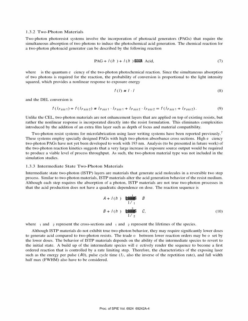
1.3.2 Two-Photon Materials
Two-photon photoresist systems involve the incorporation of photoacid generators (PAGs) that require thesimultaneous absorption of two photons to induce the photochemical acid generation. The chemical reaction fora two-photon photoacid generator can be described by the following reaction
PAG + I (h ) + I (h )
GGGGGA Acid, (7)
where is the quantum e ciency of the two-photon photochemical reaction. Since the simultaneous absorptionof two photons is required for the reaction, the probability of conversion is proportional to the light intensitysquared, which provides a nonlinear response to exposure energy
f (I ) ≈ I · I (8)
and the DEL conversion is
f (I P a s s 1) + f ( I P a s s 2) ≈ I P a s s 1 · I P a s s 1 + I P a s s 2 · I P a s s 2 = f (I P a s s 1 + I P a s s 2) . (9)
Unlike the CEL, two-photon materials are not enhancement layers that are applied on top of existing resists, butrather the nonlinear response is incorporated directly into the resist formulation. This eliminates complexitiesintroduced by the addition of an extra film layer such as depth of focus and material compatibility.
Two-photon resist systems for microfabrication using laser writing systems have been reported previously.7
These systems employ specially designed PAGs with high two-photon absorbance cross sections. High e ciencytwo-photon PAGs have not yet been developed to work with 193 nm. Analysis (to be presented in future work) ofthe two-photon reaction kinetics suggests that a very large increase in exposure source output would be requiredto produce a viable level of process throughput. As such, the two-photon material type was not included in thesimulation studies.
1.3.3 Intermediate State Two-Photon Materials
Intermediate state two-photon (ISTP) layers are materials that generate acid molecules in a reversible two stepprocess. Similar to two-photon materials, ISTP materials alter the acid generation behavior of the resist medium.Although each step requires the absorption of a photon, ISTP materials are not true two-photon processes inthat the acid production does not have a quadratic dependence on dose. The reaction sequence is
A + I (h ) 1
E GGGGGGGGGGGGC1 / 1
B
B + I (h ) 2
E GGGGGGGGGGGGC1 / 2
C , (10)
where 1 and 2 represent the cross-sections and 1 and 2 represent the lifetimes of the species.
Although ISTP materials do not exhibit true two-photon behavior, they may require significantly lower dosesto generate acid compared to two-photon resists. The trade o between lower reaction orders may be o set bythe lower doses. The behavior of ISTP materials depends on the ability of the intermediate species to revert tothe initial state. A build up of the intermediate species will e ectively render the sequence to become a firstordered reaction that is controlled by a rate limiting step. Therefore, the characteristics of the exposing lasersuch as the energy per pulse (A0), pulse cycle time (t f , also the inverse of the repetition rate), and full widthhalf max (FWHM) also have to be considered.
Proc. of SPIE Vol. 6924 69242A-4

1.3.4 Optical Threshold Materials
Optical threshold layers (OTLs) are materials that require the absorption of a threshold exposure dose to inducea photochemical event. The exposure threshold gives the material a region of nonlinear response to exposuredose and allows OTLs to be used as double exposure resists. Nonlinearity derives from the fact that any doseabsorbed below the threshold does not cause reactions to occur.
Above the dose threshold, a step change in conversion occurs and is described by the following piecewisefunction
f (I ) =
[P A C ]t h , E A c t u a l ≥ E t h1 , E A c t u a l < E t h
, where E A c t u a l =
p u l s e sI · dt , (11)
where E A c t u a l and E t h represent the actual dose received by the material and the threshold dose, respectively.[P A C ]t h is the step wise conversion concentration of the photoactive compound after reaching E t h . Equation 11shows the behavior of an ideal OTL material.
Analogous thermal resist systems are already in use in the printing industry.8 Thermal resists rely upon athermal image instead of an optical image. These systems can, for example, function by exploitation of a phasechange that is inherently threshold-like. If a material is heated to a temperature just below its melting pointand then cooled, it does not “remember” the previously applied thermal dose. Chapman et al. have investigatedinorganic thermal resist systems9 that use Bi/In bilayers as an etch masking layer for silicon. However, the useof Bi and In metals are not compatible with the photolithography process as the target semiconductor devicesare very susceptible to metal contamination. Chemical systems with similar properties for optical images haveto be developed to use this technology with lithographic imaging systems.
1.4 Feasibility Studies
These materials are not the only possibilities, but they do provide a reasonable range of resist designs to explorethe feasibility of DEL as a technology choice. Of the proposed materials, only CELs and two-photon materialshave been extensively studied and have established chemical systems. ISTP and OTL materials do not currentlyexist for use in semiconductor applications. However, their theoretical mechanisms are considered to test theirviability as a possible DEL candidates. This work investigates the feasibility of the materials for use in DELapplications through simulation and is meant to guide our materials development e ort.
2. SIMULATION CONDITIONS
The performance of the di erent material types in double exposure mode and the dependence on their materialproperties were evaluated by computer simulation using a combination of PROLITH lithography simulator andcustom code. In all cases, the optical imaging portion was performed with PROLITH. The material responses ofthe reversible CEL was studied using the PROLITH simulator. However, commercial models for the ISTP andOTL materials do not yet exist as the materials are not currently used in production, so a custom simulator wasdeveloped to model the material behaviors in these systems.
2.1 Imaging Setup
A half pitch CD of 25 nm was targeted using a 1.2 NA water immersion exposure system in double exposure mode.This is an e ective k1 of 0.155. An azimuthally polarized cross-quadrupole with c e n t e r = 0.8 and r a d i u s = 0.15was used as the illuminator. Di erent masks were used for each of the two exposure passes. The masks were 50nm line/space phase shift masks with 6 % attenuation. The two masks were o set by 50 nm between exposurepasses. As described previously,2 DEL with positive tone resists is a trench-based process as opposed to theline-based process expected with a single exposure pass. Consequently, the target line is expected to form atthe interface of the opaque and bright regions as opposed to the center of the bright regions. A focus-exposurematrix was run for each material system, and the resulting CD was observed.
Proc. of SPIE Vol. 6924 69242A-5

Table 1. Parameters used for the base resist system.
Property Value
n 1.70Dill A (µm − 1) 0
Dill B (µm − 1) 1.47Dill C (cm2 /mJ) 0.0478
[Q]/[PAG] 0.2M t h 0.75
DH (nm2 /s) 0.223DQ (nm2 /s) 0.0
ka (1/s) 0.100kb (1/s) 4.85 × 10⁸
2.2 Film Stack and Base Resist System
The film stack consisted of 50 nm of resist on 31 nm of a single layer of bottom anti-reflective coating (BARC)(n = 1.82, k = 0.46). The substrate was silicon with a 2 nm layer of SiO2. The resist simulations were basedupon a typical 193 nm resist system. The base resist parameters are shown in Table 1. In the case of the OTLand ISTP materials, the acid generation behavior di ers from the base resist and was described with custommodels.
2.3 Reversible CEL Simulation Parameters
To study the CEL behavior, a 50 nm CEL was applied on top of the film stack. The Dill A parameter was variedfrom 10 µm − 1 to 50 µm − 1. The CEL parameters are shown in Table 2. Since a reversible CEL system provides
Table 2. Simulation parameters used for the reversible CEL material.
Parameter Value
n 1.69Dill A µm − 1 0 − 50
Dill B µm − 1 0
Dill C (cm2 /mJ) 0.11
better performance than an irreversible system, the rCEL was selected for the study.
2.4 ISTP Simulation Parameters
To study the performance of the ISTP material, the acid generation behavior described in the previous sectionwas solved using a 4th order Runge-Kutta method.10 The parameters and values used in the simulation arelisted in Table 3. To simplify the calculations, 2 was assumed to be very large such that the conversion of theintermediate species to acid is assumed to be irreversible.
2.5 OTL Simulation Parameters
The OTL acid generation behavior described in the previous section was implemented. A dose threshold, E t h ,of 10 mJ /cm2 was used with a threshold photoacid compound conversion, [P A C ]t h , value of 0.75.
Proc. of SPIE Vol. 6924 69242A-6

A=01im1 A=101im1 A=201im1
—JoII Pos!t!on (nm)
A = 30 jim1
—xi —20Position (nm)
A = 50 jim1
-)O —201< Position (nm
A = 40 jim1
Table 3. Simulation parameters used for the ISTP material.
Parameter Value
1 (cm2 /mJ) 0.235 2 (cm2 /mJ) 0.235
1 (s) 0.006t f (s) 0.00025
A0 (mJ /cm2) 0.05 1
FWHM (ns) 20
3. RESULTS AND DISCUSSION
All three materials yielded nonlinear resist response when used in double exposure mode. The resist profiles areshown in Figure 3 to Figure 5 and summarized in Table 4.
Figure 3. Resist profile of rCEL with varying Dill A parameter.
The simulation results from the focus-exposure experiments were analyzed using ProDATA to generate sim-ulated Bossung plots and exposure latitude (EL) versus depth of focus (DOF) plots. The results are shown in
Proc. of SPIE Vol. 6924 69242A-7

PROLITH
—10 0X Position (nm)
PROLITH
—10 0X Position (nm)
Figure 4. Resist Profile for ISTP material.
Figure 5. Resist Profile for OTL material.
Figure 6 to Figure 8 and are summarized in Table 5. Simulated EL versus DOF plots with respect to the di erentDill A parameters are shown in Figure 9.
It is important to note that CD was the only output metric considered in the process window calculations.In most manufacturing environments, other parameters such as sidewall angle and resist loss would also need tobe optimized to produce functional devices. However, the main goal of this work is to demonstrate the proof ofconcept of the theoretical materials. Optimization of such parameters is beyond the scope of this work.
Figure 3 shows the e ects of the Dill A parameter on the resist profile. For the test case of a Dill A parameterof 0 µm − 1 , no resist profile was observed. This finding is consistent with the behavior of conventional resistssince no nonlinearity was applied and further verified that the DEL process does not provide resolved images inconventional resists.
In all cases, increasing the Dill A parameter decreased resist loss and improved the shape of the resultingimage. Figure 9 shows that the process window was also widened with the increase. Increasing the Dill A param-
Proc. of SPIE Vol. 6924 69242A-8

Q1 iS.,si. F&ten en LEtsi. Ftar rOEL A = 20 um-1 tar rOEL A = 20 um-1
Expasure Latitude (30)0.8
0740 • 3555
7 ej g 0.6C .7,e 3525
0.530 .-.. 3545
sees 0.4t 3555
3575 0.320 .. 0.2
0.1
00 —-0.2 -0.1 0.0 0.1 0.00 0.02 0.04 0.06 0.08 0.10 0.12 0.14 0.16
Eaaus Depth at Eaaus
Q1 iS.,si. F&ten en LEtsi. Ftar 'SIP AO = O.O5mJlcm2, laul = O.006s tar 'SIP AO = O.O5mJlcm2, laul = O.006s
Expasure Latitude (V©)
40 :* / / / 3600/ / 3650
30 1. .7 37.00 23750
I3800
20j-0.2 -0.1 0.0 0.1 0.00 0.02 0.04 0.06 0.08 0.10 0.12 0.14 0.16 0.18 0.20
Eacus Depth at Eacus
Q1 iS.,si. F&ten en LEtsi. Ftar OIL Eth = 1 OmJlcm2, PACth = 0.75 tar OIL Eth = 1 OmJlcm2, PACth = 0.75
Exposure Latitude (V©)
3700 640 / 7 / 3750
4/ / 380038.5039.003950
30
I--- 41.00
20t
-ittt 41.50
-0.2 -0.1 0.0 0.1 0.2 0.00 0.02 0.04 0.06 0.08 0.10 0.12 0.14 0.16 0.18 0.20 0.22Focus Depth at Focus
Figure 6. Simulated Bossung plot and EL versus DOF for rCEL material.
Figure 7. Simulated Bossung plot and EL versus DOF for ISTP material.
Figure 8. Simulated Bossung plot and EL versus DOF for OTL material.
Proc. of SPIE Vol. 6924 69242A-9

A(m1)10 15 20 25 30 35 40 45 50
2.5 I I I 120—+—AlOum&1—4-—A20um&1 110—*—A30um&1
'i'':': :'::'.'. o_________________ 70
°:0 0.02 0.04 0.06 0.08 0.1 0.12 0.14 0.16 0.18
Depth of Focus (nm)
Table 4. Summary of resist profile metrology.
MaterialDose Sidewall Resist
(mJ /cm2) Angle (o) Loss (nm)rCEL A = 10 µm − 1 24.6 74.9 32.2rCEL A = 20 µm − 1 38.2 74.4 25.0rCEL A = 30 µm − 1 56.4 71.1 18.0rCEL A = 40 µm − 1 79.6 70.2 8.1rCEL A = 50 µm − 1 108 74.8 2.0
ISTP 36.5 71.9 18.8OTL 39.3 81.9 0.2
Figure 9. Process windows of rCEL materials varying the Dill A parameter.
eter showed improvement for EL. However, only marginal improvement was observed for the DOF. Increasingthe Dill A parameter also led to increases in the dose requirement. An increase in the Dill A parameter from 10µm − 1 to 50 µm − 1 required approximately 4.4 fold increase in dose. Another factor to consider is the feasibilityof obtaining rCEL materials with high Dill A values. Without increasing the Dill A parameter, it is theoreticallypossible to increase the absorbance of the rCEL layer by increasing the layer thickness. However, the obliqueincident angles resulting from operating at N A values greater than 1 may lead to loss in depth of focus if thelayer becomes too thick. rCEL materials showed nonlinear behavior in DEL mode, however, image quality andprocess window improvement was only observed for rCELs with very high Dill A parameters (> 30 µm − 1). Evenif physical analogs with such high Dill A parameters are obtainable, the improvements are marginal and comeat the cost of large dose increases.
Table 4 shows that an rCEL with Dill A parameter of 20 µm − 1 has a comparable dose requirement to thatof ISTP and OTL materials. Results from this run were used for subsequent comparisons with ISTP and OTLmaterials.
Figure 4 shows the resist profile of the ISTP material. The profile is comparable to rCEL having slightlylower sidewall angle, 71.9 o, and reduced resist loss, 18.8 nm. Table 5 shows that ISTP has a larger processwindow than rCEL. The parameters of interest a ecting the nonlinear acid generation behavior of the materialare the energy delivered per pulse, A0, and the reversible rate constant of the intermediate state, 1 / 1. For agiven set of laser parameters, large values of A0 or 1 lead to faster conversion of PAC thus reducing the requiredexposure dose. However, the dose reduction also leads to a decrease in nonlinearity. Since the laser can onlydeliver integer numbers of pulses, the magnitude of A0 has to be within a manageable increment such that small
Proc. of SPIE Vol. 6924 69242A-10

Table 5. Summary of process windows for the rCEL, ISTP, and OTL materials.
Material Depth of Focus (µm) Exposure Latitude (%)rCEL 0.105 0.58ISTP 0.124 3.22OTL 0.137 5.06
deviations in the pulse delivery will not drastically a ect the CD. The parameters had to be optimized so thatthe system will retain nonlinear behavior but at the same time yield features within reasonable exposure doseranges. ISTP materials showed a larger process window and improved resist profile than rCEL, and could be apotential DEL material provided that materials with the specified kinetics and time constants can be identified.
Figure 5 shows the resist profile of the OTL material. The profile shows a significant reduction in resistloss compared to both rCEL and ISTP resist profiles and slight improvement in the sidewall angle. The OTLmaterial also has the largest process window of the three materials investigated. The threshold dose requirementbehavior of the OTL material served e ectively to filter out regions of low intensity. In addition, the thresholdconversion response of the PAC resulted in improved image contrast. Because no such physical systems exist,the threshold dose, E t h , and PAC conversion, [P A C ]t h , were chosen such that they would provide a definedsolubility switch within comparable dose ranges. Performance in physical systems may di er depending on thethresholding mechanism. OTL materials showed the best performance (i.e. largest process window and bestresist profile) compared to rCEL and ISTP materials and would be suitable for DEL applications. This suggeststhat potential mechanisms, either chemical or physical, need to be explored.
4. CONCLUSIONS
DEL o ers several advantages over DPL, but it requires new materials with nonlinear dose response. We haveemployed simulations to explore several potential DEL material options. The modeling results show that two-photon materials will not be feasible unless achievable laser peak power in exposure tools can be significantlyincreased. rCEL materials demonstrated nonlinear behavior in DEL mode, however, image quality and processwindow improvement was only observed for rCELs with very high Dill A parameters (> 30 µm − 1). Even ifphysical analogs with such high Dill A parameters are obtainable, the improvements are marginal. ISTP materialsshowed a larger process window than rCEL. The challenges with this approach are identifying materials withthe specified kinetics and the ability to tune the time constants. OTL materials showed the best performancewith the largest process window and best resist profile. There are no physically functional optical analogs withthe thresholding behavior. Potential mechanisms, either chemical or physical, need to be explored. From ourfeasibility studies, we believe that the ISTP and OTL materials have the greatest potential for use in DELapplications and warrant our investment in materials development.
ACKNOWLEDGMENTS
The authors would like to thank SEMATECH for financial support of this project, KLA-Tencor for the donationsof PROLITH and ProDATA licenses, Mark Smith and Trey Graves of KLA-Tencor, and Intel Corporation forthe donations of simulation machines.
Disclaimers
SEMATECH, and the SEMATECH logo are registered servicemarks of SEMATECH, Inc. All other servicemarksand trademarks are the property of their respective owners.
Proc. of SPIE Vol. 6924 69242A-11

REFERENCES
[1] Gri ng, B. F. and West, P. R., “Contrast enhanced lithography,” Solid State Technology 28(5), 152–7(1985).
[2] Byers, J., Lee, S., Jen, K., Zimmerman, P., Turro, N. J., and Willson, C. G., “Double exposure materials:Simulation study of feasibility,” Journal of Photopolymer Science and Technology 20(5), 707–717 (2007).
[3] Krayushkin, M. M., Uzhinov, B. M., Martynkin, A. Y., Dzhavadov, D. L., Kalik, M. A., Ivanov, V. L.,Stoyanovich, F. M., Uzhinova, L. D., and Zolotarskaya, O. Y., “Thermally irreversible photochromicdithienylethenes,” International Journal of Photoenergy 1(3), 183–190 (1999).
[4] Becker, R. S. and Michl, J., “Photochromism of synthetic and naturally occurring 2H-chromenes and 2H-pyrans,” Journal of the American Chemical Society 88(24), 5931–3 (1966).
[5] Grant, B. D., Clecak, N. J., Twieg, R. J., and Willson, C. G., “Deep UV photoresists I. Meldrum’s diazosensitizer,” IEEE Transactions on Electron Devices 28(11), 1300–1305 (1981).
[6] West, P. R., Davis, G. C., and Gri ng, B. F., “Contrast enhanced photolithography: application of photo-bleaching processes in microlithography,” Journal of Imaging Science 30(2), 65–8 (1986).
[7] Kuebler, S. M., Braun, K. L., Zhou, W., Cammack, J. K., Yu, T., Ober, C. K., Marder, S. R., and Perry,J. W., “Design and application of high-sensitivity two-photon initiators for three-dimensional microfabrica-tion,” Journal of Photochemistry and Photobiology A: Chemistry 158(2-3), 163–170 (2003).
[8] Gelbart, D. and Karasyuk, V. A., “UV thermoresists: sub-100-nm imaging without proximity e ects,” Proc.SPIE 3676(2), 786–793 (1999).
[9] Chapman, G. H., Tu, Y., and Peng, J., “Wavelength invariant Bi/In thermal resist as a Si anisotropic etchmasking layer and direct-write photomask material,” Proc. SPIE 5039, 472–483 (2003).
[10] Chapra, S. C. and Canale, R. P., [Numerical Methods For Engineers: With Software and Programming ],McGraw-Hill, New York, 4th ed. (2002).
Proc. of SPIE Vol. 6924 69242A-12