an agile manufacturing system for large workspace applications … · parallel kinematic mechanisms...
TRANSCRIPT
HAL Id: lirmm-00808440https://hal-lirmm.ccsd.cnrs.fr/lirmm-00808440
Submitted on 5 Apr 2013
HAL is a multi-disciplinary open accessarchive for the deposit and dissemination of sci-entific research documents, whether they are pub-lished or not. The documents may come fromteaching and research institutions in France orabroad, or from public or private research centers.
L’archive ouverte pluridisciplinaire HAL, estdestinée au dépôt et à la diffusion de documentsscientifiques de niveau recherche, publiés ou non,émanant des établissements d’enseignement et derecherche français ou étrangers, des laboratoirespublics ou privés.
An Agile Manufacturing System for Large WorkspaceApplications
Hai Yang, Cédric Baradat, Sébastien Krut, François Pierrot
To cite this version:Hai Yang, Cédric Baradat, Sébastien Krut, François Pierrot. An Agile Manufacturing System forLarge Workspace Applications. FAIM: Flexible Automation and Intelligent Manufacturing, Jun 2013,Porto, Portugal. International Workshop, WRSM 2013, Co-located with FAIM 2013, Porto, Portugal,June 26-28, 2013. Proceedings, Communications in Computer and Information Science (371), pp.57-70, 2013, Robotics in Smart Manufacturing. <10.1007/978-3-642-39223-8_6>. <lirmm-00808440>

An Agile Manufacturing System for Large Workspace
Applications
Hai Yang1, Cédric Baradat
1, Sébastien Krut
2, and François Pierrot
2
1 Industry and Transport Division, Tecnalia France
672, rue du Mas de Verchant, Montpellier 34000, France {hai.yang, cedric.baradat}@tecnalia.com
2 Robotics Department, LIRMM CNRS
161, rue Ada, Montpellier 34000, France {sebastien.krut, francois.pierrot}@lirmm.fr
Abstract. REMORA aims at offering an agile robotic solution for
manufacturing tasks done on very large parts (e.g.: very long and slender parts
found in aeronautic industries). For such tasks, classical machine-tools are
designed at several tens of meters. Both their construction and operation require
huge infrastructure supports. REMORA is a novel lightweight concept and
flexible robotic solution that combines the ability of walking and
manufacturing. The robot is a mobile manufacturing system which can
effectuate operations with good payload capacity and good precisions for large
workspace applications. This new concept combines parallel kinematics to
ensure high stiffness but low inertia, and mobile robotics to operate in very
large workspaces. This results in a machining center of new generation: 1.Agile
manufacturing system for large workspace applications; 2.Heavy load and good
precisions; 3.5-axis machining and 5-axis locomotion/clamping; 4.Self-
reconfigurable for specific tasks (workspace and force); 5.Flexible and
multifunctional (machining, fixtures…).
Keywords: Agile manufacturing, Mobile manufacturing, Parallel Kinematics,
Redundancy
1 Introduction
Modern industries and services request larger and larger pieces of equipment: aircraft spars, pipelines sections, wind turbine wings and hubs, etc. The increasing size of such equipment requires the appropriate means of manufacture, which sets great challenges for the machine-tool industry. For these tasks, existing solutions are at their limits [1]. Stationary arms suffer from their limited workspaces. Manipulators mounted on vehicles are often not accurate and rigid enough. Classical machine-tools must be designed at mega-scale (several tens of meters). In order to introduce mobile robotic solutions to certain large workpiece manufacturing processes, one has to consider problems linked to: locomotion, stiffness and localization in large workspaces.
Parallel kinematic mechanisms (PKMs) which have a great potential to provide high rigidity and motion dynamics suffer from an inherent limitation in their operational workspace. Legged robots have attracted attention because of their relatively good terrain crossover capacity. Although, numerous works on legged robots have led to remarkable improvements on various aspects such as mobility [2], dynamics equilibrium [3], payload capacity [4] etc., most of these robots are designed for exploration or military purposes. Few of them have been used to solve industrial problems due to control complexity and lack of reliability [5].
The development reported in this paper is related to an innovative robot which combines the ability to walk on the workpiece (or on the tooling that supports the workpiece) together with manufacturing ability. The mechanical concept is based on a redundancy parallel mechanism: eight motors for six degrees-of-freedoms (DoFs). Combining motors, brakes, clamping devices and numerous position sensors, the robot can clamp itself on a tooling for the manufacturing tasks, and then it can change its configuration to become a walking robot able to reach the next working area. The overall system and the function modes of the robot are presented firstly, and then the issues of redundancy are briefly addressed. Based on the built prototype, a typical step of the robot is illustrated. In the end, the advantages and potential applications as well as future works are discussed.
2 System Description
REMORA is an industry-oriented legged/parallel robot which has several specific features such as lockers on certain joints, clamping device on the extremity of each limb. Combining with proper control strategies, the robot switches between different working modes for achieving manufacturing tasks in large workspaces.
2.1 Overall Description of Robot
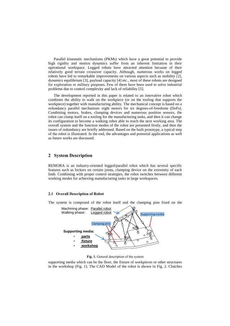
The system is composed of the robot itself and the clamping pins fixed on the
supporting media which can be the floor, the fixture of workpieces or other structures in the workshop (Fig. 1). The CAD Model of the robot is shown in Fig. 2. Clutches
Fig. 1. General description of the system
Supporting media: • parts
• fixture
• workshop
• …
Machining phase: Parallel robot Walking phase: Legged robot

are fitted on several passive joints of the robot. Furthermore, there is a clamping device on the extremity of each limb, which provides climbing capacity to the robot.
2.2 Working Mode
The robot works in two kinds of working modes:
Payload Platform (PP) mode: As illustrated in Fig. 3, every limb of the robot is attached to the supporting media. Each limb possesses six DoFs; two of them are actuated. The PP of the robot, which has six DoFs, is actuated by eight linear jacks located in the four limbs connected to the base. Therefore, in this mode the robot can be considered as a six DoFs PKM with actuation redundancy.
Fig. 3. PP Working Mode - Parallel robot (6-dof platform; 8 actuators)
Fig. 2. CAD of the robot
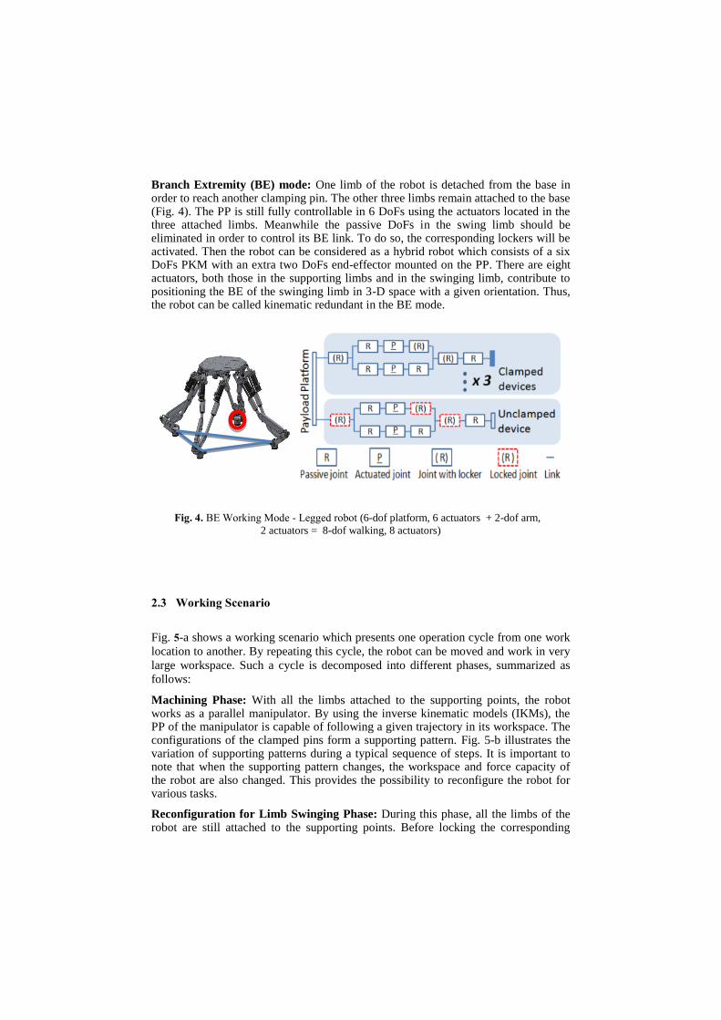
Branch Extremity (BE) mode: One limb of the robot is detached from the base in order to reach another clamping pin. The other three limbs remain attached to the base (Fig. 4). The PP is still fully controllable in 6 DoFs using the actuators located in the three attached limbs. Meanwhile the passive DoFs in the swing limb should be eliminated in order to control its BE link. To do so, the corresponding lockers will be activated. Then the robot can be considered as a hybrid robot which consists of a six DoFs PKM with an extra two DoFs end-effector mounted on the PP. There are eight actuators, both those in the supporting limbs and in the swinging limb, contribute to positioning the BE of the swinging limb in 3-D space with a given orientation. Thus, the robot can be called kinematic redundant in the BE mode.
2.3 Working Scenario
Fig. 5-a shows a working scenario which presents one operation cycle from one work
location to another. By repeating this cycle, the robot can be moved and work in very
large workspace. Such a cycle is decomposed into different phases, summarized as
follows:
Machining Phase: With all the limbs attached to the supporting points, the robot works as a parallel manipulator. By using the inverse kinematic models (IKMs), the PP of the manipulator is capable of following a given trajectory in its workspace. The configurations of the clamped pins form a supporting pattern. Fig. 5-b illustrates the variation of supporting patterns during a typical sequence of steps. It is important to note that when the supporting pattern changes, the workspace and force capacity of the robot are also changed. This provides the possibility to reconfigure the robot for various tasks.
Reconfiguration for Limb Swinging Phase: During this phase, all the limbs of the robot are still attached to the supporting points. Before locking the corresponding
Fig. 4. BE Working Mode - Legged robot (6-dof platform, 6 actuators + 2-dof arm,
2 actuators = 8-dof walking, 8 actuators)

joints, the PP will move to a specific position with a given pose in order to have all the required lockable joints in the desired positions for locking. Properly choosing the locking poses is one of the key issues for ensuring the robot to reach the desired next clamping pin.
Limb Swinging Phase: With the corresponding lockers activated, the extremity of the swinging limb can follow a given 6-axis trajectory to the next supporting point. Such swinging phase is divided into three sub-phases: Extraction of the limbs, Free swinging and Insertion of the limbs.
3 Redundant Issues
As it has been mentioned in the previous section, there are two kinds of redundancies appearing in the structure during the different working modes: the actuation redundancy for the PP mode and the kinematic redundancy for the BE mode, respectively. Appropriate management of the redundancies is one of the key issues for ensuring a good realization of tasks.
3.1 Actuation Redundancy
Actuation redundancy is an interesting feature for improving the workspace properties of parallel robots: (1) it helps to build PKMs with larger singularity-free workspace; (2) it also helps to homogenize the force performances over the whole workspace [6].
However the control of PKMs with actuation redundancy can be a source of problems. The PID control loops shown in Fig. 6 is the most implemented controller
Fig. 5. a. Working scenario; b. Typical sequence of steps
Fig. 6. Conventional control scheme
in most industrial applications. T.G. stands for Trajectory generator, QIKMX is the inverse kinematics model of PKMs with the pose variable x as the input and the actuator variable q as output, PID is the proportional, integral and derivative control block, xd is the desired pose variable of the PP, qd is the desired actuator positions, qm is the measured actuator positions, q is the difference between the desired actuator positions and the measured actuator positions, the actuators forces can be considered as proportional to f, the input of actuator amplifiers are set in torque mode.
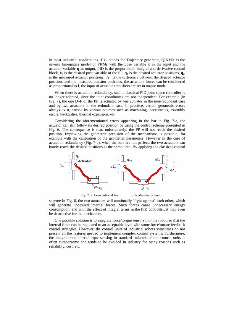
When there is actuation redundancy, such a classical PID joint space controller is no longer adapted, since the joint coordinates are not independent. For example (in Fig. 7), the one DoF of the PP is actuated by one actuator in the non-redundant case and by two actuators in the redundant case. In practice, certain geometric errors always exist, caused by various sources such as machining inaccuracies, assembly errors, backlashes, thermal expansion, etc.
Considering the aforementioned errors appearing in the bar in Fig. 7-a, the actuator can still follow its desired position by using the control scheme presented in Fig. 6. The consequence is that, unfortunately, the PP will not reach the desired position. Improving the geometric precision of the mechanisms is possible, for example with the calibration of the geometric parameters. However in the case of actuation redundancy (Fig. 7-b), when the bars are not perfect, the two actuators can barely reach the desired positions at the same time. By applying the classical control
scheme in Fig. 6, the two actuators will continually ‘fight against’ each other, which will generate undesired internal forces. Such forces cause unnecessary energy consumption, and with the effect of integral terms in the PID controller, it may even be destructive for the mechanism.
One possible solution is to integrate force/torque sensors into the robot, so that the internal force can be regulated to an acceptable level with some force/torque feedback control strategies. However, the control units of industrial robots sometimes do not present all the features needed to implement complex control systems. Furthermore, the integration of force/torque sensing in standard industrial robot control units is often cumbersome and tends to be avoided in industry for many reasons such as reliability, cost, etc.
Fig. 7. a. Conventional bar; b. Redundancy bars
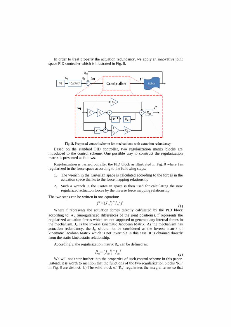
In order to treat properly the actuation redundancy, we apply an innovative joint space PID controller which is illustrated in Fig. 8.
Based on the standard PID controller, two regularization matrix blocks are introduced to the control scheme. One possible way to construct the regularization matrix is presented as follows.
Regularization is carried out after the PID block as illustrated in Fig. 8 where f is regularized in the force space according to the following steps:
1. The wrench in the Cartesian space is calculated according to the forces in the actuation space thanks to the force mapping relationship.
2. Such a wrench in the Cartesian space is then used for calculating the new regularized actuation forces by the inverse force mapping relationship.
The two steps can be written in one equation:
(1) Where f represents the actuation forces directly calculated by the PID block
according to q (unregularized differences of the joint positions), fr represents the
regularized actuation forces which are not supposed to generate any internal forces in
the mechanism. Jm is the inverse kinematic Jacobean Matrix. As the mechanism has
actuation redundancy, the Jm should not be considered as the inverse matrix of
kinematic Jacobian Matrix which is not invertible in this case. It is obtained directly
from the static kinetostatic relationship.
Accordingly, the regularization matrix Rts can be defined as:
(2) We will not enter further into the properties of such control scheme in this paper.
Instead, it is worth to mention that the functions of the two regularization blocks ‘Rts’ in Fig. 8 are distinct. 1.) The solid block of ‘Rts’ regularizes the integral terms so that
Fig. 8. Proposed control scheme for mechanisms with actuation redundancy
it will not diverge in the case of actuation redundancy. 2.) The dashed block of ‘Rts’ is supposed to minimize the internal force in the structure. Theoretically, the internal force can be zero by applying the dashed block of ‘Rts’.
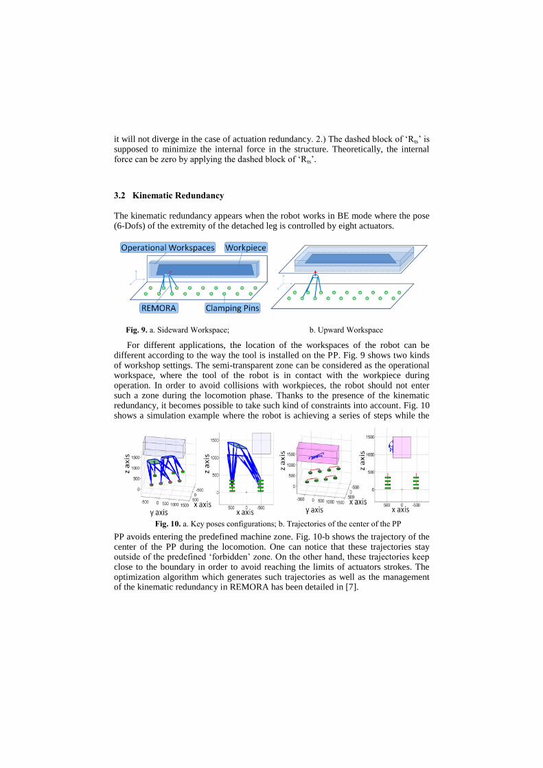
3.2 Kinematic Redundancy
The kinematic redundancy appears when the robot works in BE mode where the pose (6-Dofs) of the extremity of the detached leg is controlled by eight actuators.
For different applications, the location of the workspaces of the robot can be different according to the way the tool is installed on the PP. Fig. 9 shows two kinds of workshop settings. The semi-transparent zone can be considered as the operational workspace, where the tool of the robot is in contact with the workpiece during operation. In order to avoid collisions with workpieces, the robot should not enter such a zone during the locomotion phase. Thanks to the presence of the kinematic redundancy, it becomes possible to take such kind of constraints into account. Fig. 10 shows a simulation example where the robot is achieving a series of steps while the
PP avoids entering the predefined machine zone. Fig. 10-b shows the trajectory of the center of the PP during the locomotion. One can notice that these trajectories stay outside of the predefined ‘forbidden’ zone. On the other hand, these trajectories keep close to the boundary in order to avoid reaching the limits of actuators strokes. The optimization algorithm which generates such trajectories as well as the management of the kinematic redundancy in REMORA has been detailed in [7].
Fig. 9. a. Sideward Workspace; b. Upward Workspace
Fig. 10. a. Key poses configurations; b. Trajectories of the center of the PP
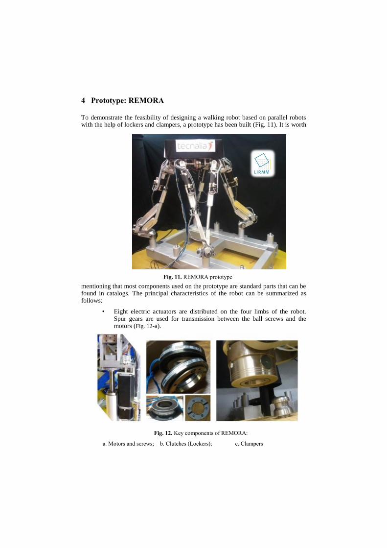
4 Prototype: REMORA
To demonstrate the feasibility of designing a walking robot based on parallel robots with the help of lockers and clampers, a prototype has been built (Fig. 11). It is worth
mentioning that most components used on the prototype are standard parts that can be found in catalogs. The principal characteristics of the robot can be summarized as follows:
• Eight electric actuators are distributed on the four limbs of the robot. Spur gears are used for transmission between the ball screws and the motors (Fig. 12-a).
Fig. 11. REMORA prototype
Fig. 12. Key components of REMORA:
a. Motors and screws; b. Clutches (Lockers); c. Clampers
• Three electric clutches (Fig. 12-b) are equipped on each limb, so there are 12 clutches in total, plus one brake on each motor for security. Because of difference required locking forces, the clutches near the extremity of the limbs have friction disks, while those on the PP side are with dented disks.
• A pneumatically actuated clamping device is used at the extremity of each limb (Fig. 12-c). In industry, these clamping devices are usually used for holding parts to be machined. In terms of clamping force, repeatability and misalignment tolerance, they are the ideal choice for our application.
• The control system is based on xPCTarget which is a real time module in Simulink. An advantage of this system is that users with Simulink programming skills can execute Simulink models on a target computer for real-time testing applications.
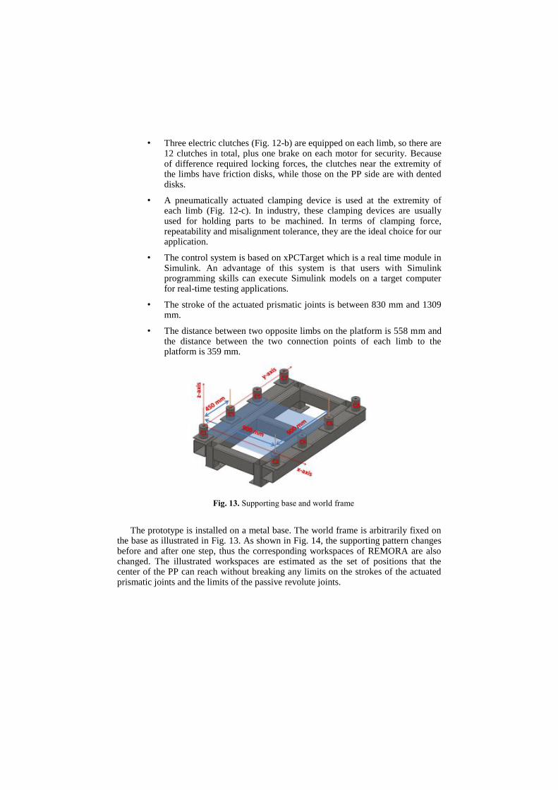
• The stroke of the actuated prismatic joints is between 830 mm and 1309 mm.
• The distance between two opposite limbs on the platform is 558 mm and the distance between the two connection points of each limb to the platform is 359 mm.
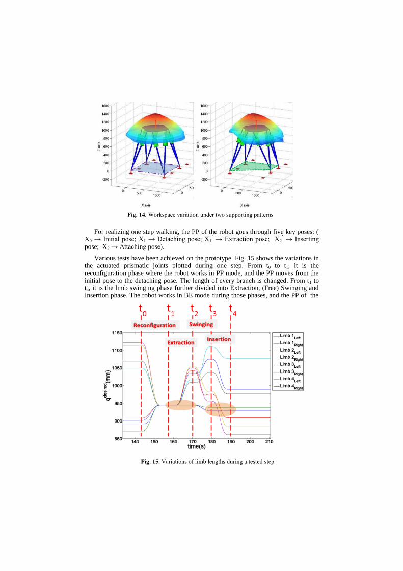
The prototype is installed on a metal base. The world frame is arbitrarily fixed on the base as illustrated in Fig. 13. As shown in Fig. 14, the supporting pattern changes before and after one step, thus the corresponding workspaces of REMORA are also changed. The illustrated workspaces are estimated as the set of positions that the center of the PP can reach without breaking any limits on the strokes of the actuated prismatic joints and the limits of the passive revolute joints.
Fig. 13. Supporting base and world frame
For realizing one step walking, the PP of the robot goes through five key poses: ( X0 → Initial pose; X1 → Detaching pose; X1
’ → Extraction pose; X2
’ → Inserting
pose; X2 → Attaching pose).
Various tests have been achieved on the prototype. Fig. 15 shows the variations in the actuated prismatic joints plotted during one step. From t0 to t1, it is the reconfiguration phase where the robot works in PP mode, and the PP moves from the initial pose to the detaching pose. The length of every branch is changed. From t1 to t4, it is the limb swinging phase further divided into Extraction, (Free) Swinging and Insertion phase. The robot works in BE mode during those phases, and the PP of the
t0 t
1 t
2 t
3 t
4
Fig. 15. Variations of limb lengths during a tested step
Fig. 14. Workspace variation under two supporting patterns
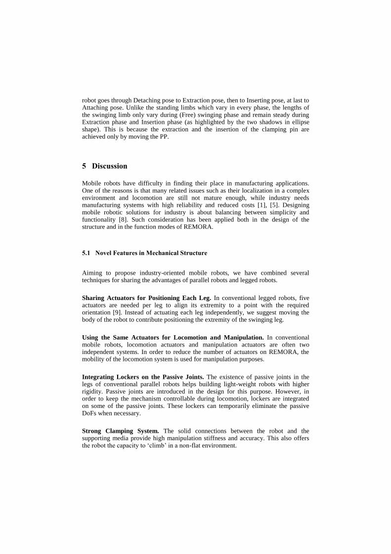
robot goes through Detaching pose to Extraction pose, then to Inserting pose, at last to Attaching pose. Unlike the standing limbs which vary in every phase, the lengths of the swinging limb only vary during (Free) swinging phase and remain steady during Extraction phase and Insertion phase (as highlighted by the two shadows in ellipse shape). This is because the extraction and the insertion of the clamping pin are achieved only by moving the PP.
5 Discussion
Mobile robots have difficulty in finding their place in manufacturing applications. One of the reasons is that many related issues such as their localization in a complex environment and locomotion are still not mature enough, while industry needs manufacturing systems with high reliability and reduced costs [1], [5]. Designing mobile robotic solutions for industry is about balancing between simplicity and functionality [8]. Such consideration has been applied both in the design of the structure and in the function modes of REMORA.
5.1 Novel Features in Mechanical Structure
Aiming to propose industry-oriented mobile robots, we have combined several techniques for sharing the advantages of parallel robots and legged robots.
Sharing Actuators for Positioning Each Leg. In conventional legged robots, five actuators are needed per leg to align its extremity to a point with the required orientation [9]. Instead of actuating each leg independently, we suggest moving the body of the robot to contribute positioning the extremity of the swinging leg.
Using the Same Actuators for Locomotion and Manipulation. In conventional mobile robots, locomotion actuators and manipulation actuators are often two independent systems. In order to reduce the number of actuators on REMORA, the mobility of the locomotion system is used for manipulation purposes.
Integrating Lockers on the Passive Joints. The existence of passive joints in the legs of conventional parallel robots helps building light-weight robots with higher rigidity. Passive joints are introduced in the design for this purpose. However, in order to keep the mechanism controllable during locomotion, lockers are integrated on some of the passive joints. These lockers can temporarily eliminate the passive DoFs when necessary.
Strong Clamping System. The solid connections between the robot and the supporting media provide high manipulation stiffness and accuracy. This also offers the robot the capacity to ‘climb’ in a non-flat environment.
Self-reconfigurability. The presented solution also provides a new method for achieving robot reconfiguration in an autonomous manner, which comprises the use of closed KCs, clamping and/or locking devices. By changing the shapes and locations of the supporting patterns, the robot can achieve self-reconfiguration in order to obtain optimized workspaces according to different applications. When compared to existing manually reconfigurable machining centers [10], [11], the suggested family of robots requires much less machine downtime by achieving reconfiguration in an autonomous way. The reconfigurability can also be interpreted from the robotics modeling point of view: the fact that robot respects same geometry constraints allows using the same mathematic models to describe the robot with different supporting patterns.
5.2 Potential Applications of REMORA
The presented robot illustrates new possibilities for the automation of some manufacturing processes in large workspaces. In the solution developed here, the fact that the posture of each supporting patterns can be measured after installation helps avoid localization issues. The precision of the prototype is partially ensured by measuring directly the position of the preinstalled clamping pins. Such measurements are carried out using common equipment such as laser trackers. As a result, when compared to the approach of high stiffness rail-based heavy machining centers, this method appears attractive to the industry in terms of costs, agility and flexibility.
In addition, allowing extending workspace of parallel robots to an unlimited large
workspace can be interesting for many manufacturing applications, particularly when
required charges and/or dynamics performances are difficult to fulfill with the
conventional mobile arm-based solutions.
5.3 Future Work
As mentioned previously, the proposed robots can be reconfigured in order to customize the robot’s performance according to application requirements. The arrangements of the supporting patterns will influence the force performance as well as the size of the local workspace during the machining mode. An advanced algorithm which is able to choose the optimal supporting patterns with respect to the desired performance should be developed in order to exploit the potential of the self-reconfigurability of the robot.
On the other hand, constraints and required functionalities might vary considerably according to applications. To reply the specific constraints of various applications, new structures can be inspired from the summarized design principles.
6 Summary
The work reported in this paper is related to a kind of mobile manipulators which is able to achieve locomotion tasks and to accomplish operations once it is deployed in its working location; in such way, some manufacturing operations can be automated in very large workspace. Several aspects such as working modes, working scenario as well as redundancy are addressed briefly. A prototype has been built and tested to illustrate the feasibility of the concept. Future work on the optimal design of the arrangement of supporting patterns as well as new structures design are expected for applications with specific requirements.
References
1. Stillstrom, C., Jackson, M.: The Concept of Mobile Manufacturing. Journal of
Manufacturing Systems. 26,188--193 (2007)
2. Spenneberg, D., McCullough, K., Kirchner, F.: Stability of Walking in a Multilegged Robot
Suffering Leg Loss. In: IEEE International Conference on Robotics and Automation, vol.3,
pp. 2159--2164, Barcelona (2004)
3. Matsumoto, O., Kajita, S., Saigo, M., Tani, K.: Dynamic Trajectory Control of Passing
Over Stairs by a Biped Type Leg-Wheeled Robot with Nominal Reference of Static Gait.
In: IEEE/RSJ International Conference on Intelligent Robots and Systems, vol.1, pp. 406--
412, Victoria (1998)
4. Buehler, M., Playter, R., Raibert, M.: Robots Step Outside. In: International symposium on
Adaptive Motion in Animals and Machines, Ilmenau (2005)
5. Armada, M., Prieto, M., Akinfiev, T., Fernandez, R., Gonzalez, P., Garcia, E., Montes, H.,
Nabulsi, S., Ponticelli, R., Sarria, J., Estremera, J., Ros, S., Grieco, J., Fernandez, G.: On
The Design And Development Of Climbing And Walking Robots For The Maritime
Industries. Journal of Maritime Research, vol. 2, no.1, pp 9--3 (2005)
6. Corbel, D., Gouttefarde, M., Pierrot, F.: Towards 100G with PKM. Is Actuation
Redundancy A Good Solution for Pick-And-Place? In: IEEE International Conference on
Robotics and Automation, pp. 4675--4682, Anchorage (2010)
7. Yang, H., Krut, S., Baradat, C., Pierrot, F.: Locomotion Approach of REMORA: A
Reconfigurable Mobile Robot for Manufacturing Applications. In: IEEE/RSJ International
Conference on Intelligent Robots and Systems, pp 5067--5072, San Francisco (2011)
8. Yoneda, K., Ota, Y.: Non-Bio-Mimetic Walkers. International Journal of Robotics
Research, vol. 22, issue.3--4, pp. 241--249 (2003)
9. Balaguer, C., Gimenez, A., Jardon, A.: Climbing Robots Mobility for Inspection and
Maintenance of 3D Complex Environments. Autonomous Robots, vol. 18, issue 2, pp. 157-
-169 (2005)
10. Xi, F., Li, Y.W., Wang, H.B.: A Module-Based Method for Design and Analysis of
Reconfigurable Parallel Robots. In: International Conference on Mechatronics and
Automation, pp. 627--632, Bangkok (2010)
11. Bi, Z.: Development and Control of a 5-Axis Reconfigurable Machine Tool. Journal of
Robotics, vol. 2011, arti. 583072, pp. 9 (2011)