an active strain sensing system based on single-longitudinal-mode distributed bragg reflector fiber...
TRANSCRIPT

TL theory. Our calculations show that the CNT interconnects can
transmit a signal for large distances, several hundred times their
diameter. Both isolated tubes and bundles exhibited near loss-free
signal propagation over lengths as large as 5 lm for a large range
of mean free paths. Our results show that crystalline bundles
could have a minimum of 10 times speed advantage over single-
walled CNTs. This is due to the lower kinetic inertia observed in
the bundles as well as the lower effective contact resistance. How-
ever, they appear more prone to phonon-induced scattering com-
pared to the single-walled nanotubes.
ACKNOWLEDGMENT
The research reported in this document was supported partly by
the contract DAAD17-03-C-0115 with the U.S. Army Research
Laboratory.
REFERENCES
1. International Technology Roadmap for Semiconductors: Intercon-
nect, 2005.
2. P.L. McEuen, M.S. Fuhrer, and H. Park, Single-walled carbon
nanotube electronics, IEEE Trans Nanotechnol 1 (2002), 78–85.
3. R. Saito, G. Dresselhaus, and M.S. Dresselhaus, Physical properties
of carbon nanotubes, World Scientific Publishing Company,
September 1998.
4. P.J. Burke, Luttinger liquid theory as a model of the gigahertz
electrical properties of carbon Nanotubes, IEEE Trans Nanotechnol
1 (2002), 129–144.
5. M. Bockrath,Carbon nanotubes: Electrons in one dimension., Ph.D.
Thesis, U. C. Berkeley, Berkeley, CA, 1999.
6. V. Parkash and A.K. Goel, Electrostatic capacitances for carbon
nanotube interconnects, Microwave Opt Technol Lett 51 (2009),
2374–2378.
7. V. Parkash and A.K. Goel, Quantum capacitance extraction for car-
bon nanotube interconnects, Nanoscale Res Lett 5 (2010),
1424–1430.
8. J. Griffith and M. Nakhla, Time-domain analysis of lossy coupled
transmission lines, IEEE Trans Microwave Theory Tech 38 (1990),
1480–1487.
9. A.K. Goel, High-speed VLSI interconnections, Wiley Interscience,
Hoboken, NJ, 2007.
VC 2011 Wiley Periodicals, Inc.
AN ACTIVE STRAIN SENSING SYSTEMBASED ON SINGLE-LONGITUDINAL-MODE DISTRIBUTED BRAGGREFLECTOR FIBER LASER AND ITSAPPLICATIONS IN THE MEASUREMENTOF ERBIUM-DOPED FIBERBIREFRINGENCE
Hao Zhang, Bo Liu, and Chenglai JiaKey Laboratory of Opto-Electronic Information and Technology,Ministry of Education, Institute of Modern Optics, NankaiUniversity, Tianjin 300071, China; Corresponding author:[email protected]
Received 12 February 2011
ABSTRACT: An active strain sensing system based on single-longitudinal-mode distributed Bragg reflector fiber laser is proposed and
experimentally demonstrated. Owing to the short laser cavity length andbirefringence-induced mode splitting, the proposed laser in single-longitudinal-mode operation provides a beat signal from 1.598 to 2.53
GHz as the strain applied onto the fiber laser changes, and through beatfrequency interrogation the proposed laser sensor turns out a strainsensitivity of �0.21 MHz/le. Moreover, by simultaneously monitoring the
laser wavelength and beat frequency, strain dependence of erbium-dopedfiber birefringence has also been measured, and experimental results
show that erbium-doped fiber birefringence has a strain sensitivity of�1.59 � 10�9/le. VC 2011 Wiley Periodicals, Inc. Microwave Opt
Technol Lett 53:2508–2512, 2011; View this article online at
wileyonlinelibrary.com. DOI 10.1002/mop.26302
Key words: fiber laser; strain sensor; single-longitudinal-mode;distributed Bragg reflector; fiber birefringence
1. INTRODUCTION
Since Hill et al. successfully fabricated the first fiber Bragg gra-
ting (FBG) in the latter half of 1970s [1], due to their distin-
guished characteristics such as electro-magnetic immunity, com-
pactness, good reliability, high sensitivity, and ease of
fabrication, FBGs have found their wide applications in both
fields of scientific research and civil engineering on a global
scale. Various types of FBG sensors have been developed for
the measurement of numerous physical parameters, including
temperature [2, 3] strain [4–7], pressure [8–10], vibration [11],
current [12], etc. Most of the FBG sensors developed in early
times belong to passive sensors which require additional light
source to provide the power supply. The remarkable progress of
FBG-based fiber lasers in recent years makes it possible that the
fiber laser itself could be utilized as the active fiber sensor.
When compared with conventional passive FBG sensors, fiber
laser sensors could offer higher signal-to-noise ratio, higher
measurement accuracy, and are suitable for long-distance and
networking applications. According to the interrogation method,
fiber laser sensors could be categorized into wavelength-encod-
ing and polarimetric fiber laser sensors. Similar to conventional
passive FBG sensors, measurement of physical measurands
could be achieved by monitoring laser wavelength for wave-
length-encoding sensors, while for polarimetric fiber laser sen-
sors, laser beat frequency that originates from the slightly split
orthogonal polarization modes could be exploited as the sensing
signal. Since it would be convenient to accomplish the interrog-
ation of sensing signals in the radiation frequency (RF) domain
with the well developed electronic technique, polarimetric fiber
laser sensors based on beat frequency interrogation have
Figure 6 Comparison of propagation delays for the CNT-based inter-
connect bus consisted of isolated SWNTs and SWNT bundles. Plots are
shown for kf ¼ 1
2508 MICROWAVE AND OPTICAL TECHNOLOGY LETTERS / Vol. 53, No. 11, November 2011 DOI 10.1002/mop

attracted considerable research interest in the past few years
[13–15].
Recently, we have developed a short cavity distributed Bragg
reflector (DBR) fiber laser temperature sensor based on beat fre-
quency interrogation [16]. As the continuation of this work, in
this article, a single-longitudinal-mode (SLM) DBR fiber laser
strain sensing system is proposed, and furthermore, by monitor-
ing laser wavelength and beat frequency in the meanwhile, the
measurement of strain dependence of erbium-doped fiber (EDF)
birefringence has been achieved as well. Since fiber birefrin-
gence plays an important role in complex polarization dynamics
of rare-earth-doped fiber lasers and it is also a vital parameter
that determines the performance of polarization-dependent opti-
cal devices using high birefringence fibers and telecommunica-
tion systems using low birefringence fibers, measurement of
fiber birefringence has been investigated by several studies [17–
22], however, complex interferometric systems needs to be con-
structed and expensive wavelength interrogation method is nor-
mally required to retrieve the fiber birefringence information
from the interference spectrum. Compared with present inter-
ferometric fiber birefringence measurement approaches, our pro-
posed scheme has several advantages such as simple structure,
low cost, compactness, and high sensitivity.
2. EXPERIMENTAL SETUP AND OPERATION PRINCIPLE
Figure 1 shows the experimental setup of the proposed SLM
DBR fiber laser strain sensing system. The fiber laser sensor has
a basic Fabry-Perot (F-P) configuration consisting of a piece of
EDF with two FBGs as cavity reflectors. A 980 nm laser diode
serves as the pump source, and to ensure SLM operation, a seg-
ment of �cm EDF [absorption coefficient: 15.2 dB/m at 979
nm; numerical aperture (NA): 0.22] is employed as the gain me-
dium. Since the cavity length is about �cm, to reduce additional
cavity loss, a couple of FBGs are directly inscribed in the EDF
with 193 nm excimer laser and phase mask method. And to
avoid the possible influence of residual pump light on the gener-
ation of laser beat frequency, backward laser output method is
adopted. Fiber tip A is pigtailed to eliminate the fiber facet
reflection, and to suppress the influence of backward reflection
light on the laser system, an optical isolator (ISO) is employed
at the signal port of a wavelength-division-multiplexer (WDM).
After the output laser is separated by a 3 dB coupler, one por-
tion of light is transmitted to an optical spectrum analyzer
(OSA) for real-time laser wavelength mentoring, and the other
portion is converted into electrical signal via a high speed
phtotodetector (PD) for beat frequency interrogation in the RF
domain through an electrical spectrum analyzer (ESA). The fiber
laser with cavity length of �cm is pasted along the central axis
of a uniform-strength beam (UCB), and thus by changing the
free end displacement of the UCB, the strain distribution over
the fiber laser could be adjusted.
According to the laser principle, laser frequency v of a cer-
tain longitudinal mode k is determined by:
m ¼ ck
2nl(1)
where c is the speed of light in vacuum, n is the refractive index
of the cavity medium, and l represents the cavity length. Since
any longitudinal mode with intensity beyond the lasing threshold
may oscillate, in most cases, several longitudinal modes may
simultaneously turn up in the oscillation cavity. From Eq. (1), it
could be seen that with the decrease of cavity length, the mode
spacing between adjacent longitudinal modes will become larger
accordingly, and hence fewer longitudinal modes will satisfy the
lasing threshold. As our proposed laser has a short cavity of
�cm, we have experimentally obtained a DBR fiber laser in
SLM operation. However, due to the presence of intrinsic fiber
birefringence, the two orthogonal polarization modes would ex-
perience slight mode splitting, and the laser frequencies corre-
sponding to x and y polarization modes could be respectively
expressed as:
mx ¼ ck
2nxl; my ¼ ck
2nyl(2)
where nx and ny refer to the refractive indices corresponding to
x and y polarization modes, respectively. Therefore, the birefrin-
gence-induced laser beat frequency Dv is determined by:
Dm ¼ mx � my ¼ ckðny � nxÞ2nxnyl
(3)
Considering the fiber birefringence is rather small relative to
the refractive index of the fiber core, the above equation could
be further modified as:
Dm ¼ Bmn
¼ Bc
nk(4)
where B refers to fiber birefringence and k is laser wavelength.
From Eq. (4), it could be seen that the birefringence-
induced laser beat frequency is codetermined by fiber birefrin-
gence, laser frequency, and refractive index of the fiber core.
Hence, any physical parameter that has some influence on the
above factors could be measured through beat frequency inter-
rogation. In our experiment, as strain applied onto the fiber
laser changes, the intrinsic fiber birefringence, laser frequency,
and refractive index of the fiber core would change accord-
ingly, leading to the shift of laser beat frequency. Thus
through beat frequency interrogation, strain measurement of
EDF can be achieved. Another interesting matter should be
addressed is that EDF birefringence could be calculated by
modifying Eq. (4) as:
B ¼ nkDmc
(5)
From the above equation, we can see that by simultaneously
monitoring the shift of laser wavelength and beat frequency
Figure 1 Schematic diagram of the proposed SLM DBR fiber laser
sensing system LD: laser diode; WDM: wavelength division multiplexer;
FBG: fiber Bragg grating; EDF: erbium-doped fiber; UCB: uniform-
strength cantilever beam; ISO: optical isolator; OSA: optical spectrum
analyzer; PD: photodetector; ESA: electrical spectrum analyzer
DOI 10.1002/mop MICROWAVE AND OPTICAL TECHNOLOGY LETTERS / Vol. 53, No. 11, November 2011 2509
while strain changes, the relationship between EDF birefrin-
gence and applied strain could also be acquired.
3. EXPERIMENTAL RESULTS AND DISCUSSION
In our experiment, two FBGs with matched reflection wave-
lengths are employed as cavity reflectors. The output laser wave-
length of this DBR fiber laser is around 1536.476 nm, as shown
in Figure 2. The number of longitudinal modes that may exist in
a DBR fiber laser is generally determined by the gain profile of
EDF and mode spacing between adjacent longitudinal modes. For
our proposed DBR fiber laser, the cavity length is about �cm,
roughly corresponding to the central points of the two FBG
reflectors. Due to the ultrashort cavity length, mode spacing is
sufficiently large to ensure SLM operation, which could be veri-
fied by the experimental observation of laser beat spectrum.
Figure 3 shows laser beat frequency spectra as strain applied
onto the fiber laser sensor changes. It is clear that for certain
EDF strain, besides the beat frequency that originates from the
mode splitting of orthogonal polarization modes for a same lon-
gitudinal mode, no more frequency component exists throughout
a frequency span of 1.5 GHz. We can also see that as the strain
applied onto the fiber laser increases, laser beat frequency
increases as well. This can be explained by analyzing the strain
dependence of beat frequency according to Eq. (4). As is well
known, the Bragg wavelength of an FBG has a red shift while
many earlier studies reveal that fiber refractive index reduces as
strain increases [23–25]. Considering the strain coefficient of fiber
refractive index is normally in the magnitude of �10�7/le [23–
25], fiber birefringence should be the main factor that determines
laser beat frequency. The experimental results in Figure 3 imply
that fiber birefringence turn to be higher as strain increases.
To apply strain onto the fiber laser sensor, a UCB with L in
length and h in thickness is utilized in our experiment. Accord-
ing to structural mechanics, the dependence of strain e at any
point along the central axis of a UCB on its free end deflection
D is determined by:
e ¼ hD
L2(6)
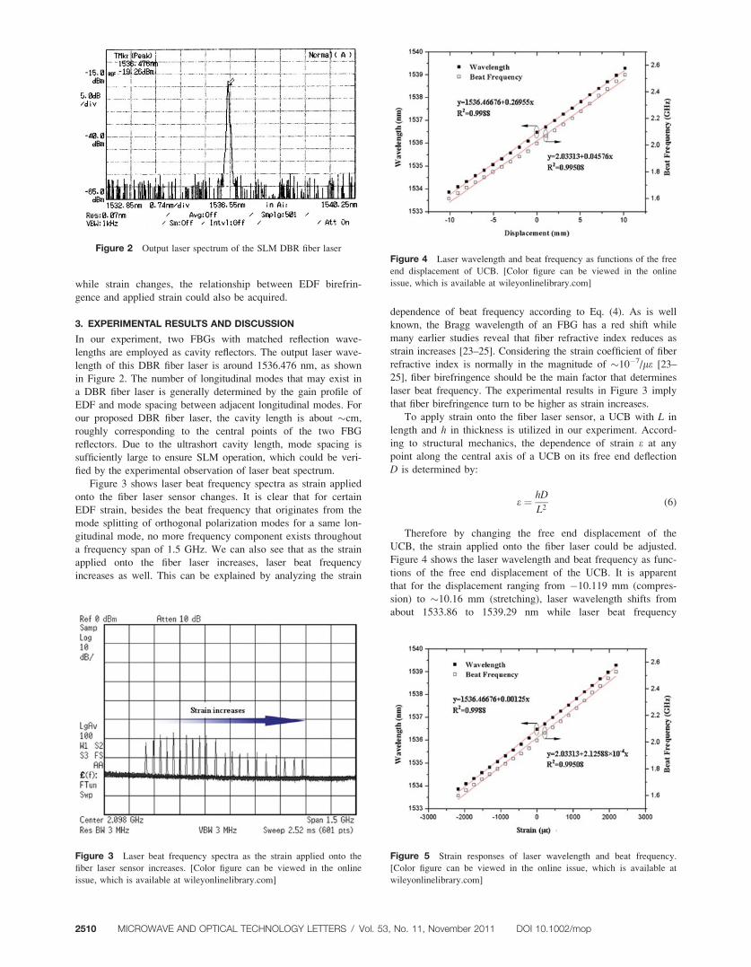
Therefore by changing the free end displacement of the
UCB, the strain applied onto the fiber laser could be adjusted.
Figure 4 shows the laser wavelength and beat frequency as func-
tions of the free end displacement of the UCB. It is apparent
that for the displacement ranging from �10.119 mm (compres-
sion) to �10.16 mm (stretching), laser wavelength shifts from
about 1533.86 to 1539.29 nm while laser beat frequency
Figure 2 Output laser spectrum of the SLM DBR fiber laser
Figure 3 Laser beat frequency spectra as the strain applied onto the
fiber laser sensor increases. [Color figure can be viewed in the online
issue, which is available at wileyonlinelibrary.com]
Figure 4 Laser wavelength and beat frequency as functions of the free
end displacement of UCB. [Color figure can be viewed in the online
issue, which is available at wileyonlinelibrary.com]
Figure 5 Strain responses of laser wavelength and beat frequency.
[Color figure can be viewed in the online issue, which is available at
wileyonlinelibrary.com]
2510 MICROWAVE AND OPTICAL TECHNOLOGY LETTERS / Vol. 53, No. 11, November 2011 DOI 10.1002/mop

increases from 1.598 to 2.53 GHz, and their coefficients of
determination reach 0.9988 and 0.99508, respectively.
Based on Eq. (6), it is convenient to acquire the strain
responses of laser wavelength and beat frequency, as shown in
Figure 5. It is clear that both of laser wavelength and beat fre-
quency have linear strain responses. Therefore, measurement of
the strain applied onto the fiber laser could be realized through
beat frequency interrogation. Besides, it should be also noted
that as strain changes from about �2178.3 to 2187.1 le, laserbeat frequency increases by 0.932 GHz with a strain sensitivity
of �0.21 MHz/le. This indicates that the proposed fiber laser
strain sensor is promising to find its applications in flexible pho-
tonic generation and control of microwave signals, which has
become a newly developing research subject in recent years.
Based on the strain responses of laser wavelength and beat
frequency, it is possible to obtain the fiber birefringence accord-
ing to Eq. (5). The refractive index of the fiber core could be
calculated with the definition of fiber NA:
NA ¼ffiffiffiffiffiffiffiffiffiffiffiffiffiffiffiffiffin2co � n2cl
q(7)
where nco and ncl represent the refractive indices of fiber core
and fiber cladding, respectively. By using the Sellmeier equa-
tion, we could calculate the refractive index dispersion of silica-
based fiber cladding for 1533.8564 to 1539.288 nm, correspond-
ing to the laser wavelength range in Figure 5. Considering the
NA of the EDF used in our experiment is 0.22, the core refrac-
tive index dispersion of EDF could be also obtained for the
above specific wavelength range. According to our previous
work on refractive index measurement for the same type EDF
as used in this work, the core refractive index of EDF has a
strain coefficient of �6.30863 � 10�7/le [26]. Therefore, we
could calculate the strain dependence of EDF birefringence, as
shown in Figure 6. It can be seen that EDF birefringence is in
proportional to the applied strain with a strain sensitivity of
�1.59 � 10�9/le, and the coefficient of determination reaches
0.99504, which is in agreement with our theoretical analysis.
4. CONCLUSION
In summary, we have proposed and experimentally demonstrated
an active strain sensing system based on an SLM DBR fiber
laser with beat frequency interrogation in the RF domain. Exper-
imental results indicate that as the strain applied onto the fiber
laser changes, laser beat frequency increases by a frequency
span of 0.932 GHz, and coefficient of determination reaches
0.99508, which ensures its suitability for practical applications.
Furthermore, the proposed fiber laser sensor is also expected to
be applied in photonic generation and control of microwave sig-
nals. Besides, we have also accomplished the measurement of
the strain dependence of EDF birefringence by simultaneously
monitoring the laser wavelength and laser beat frequency. It
should be noted that the proposed fiber birefringence measure-
ment approach is not limited to EDF, and more generally, for
any kind of active fiber under test, the same process could be
repeated so long as the fiber is employed to construct an SLM
DBR fiber laser. And therefore, in this sense this approach could
be adopted as a birefringence measurement method for active
fibers. Our proposed fiber laser sensing system has many advan-
tages such as simple configuration, ease of fabrication, high sen-
sitivity, good sensing linearity, and extendable functionality,
which ensures its potential applications in future fiber optic
sensing and related areas.
ACKNOWLEDGMENTS
This work was supported by the National Key Natural Science
Foundation of China under Grant No. 60736039, the National Nat-
ural Science Foundation of China under Grant Nos. 11004110,
10904075, 50802044, the Fundamental Research Funds for the
Central Universities, the National Key Basic Research and Devel-
opment Program of China under Grant No. 2010CB327605.
REFERENCES
1. K.O. Hill, Y. Fujii, D.C. Johnson, and B.S. Kawasaki, Photosensi-
tivity in optical fiber waveguides: Application to reflection filter
fabrication, Appl Phys Lett 32 (1978), 647–649.
2. B. Zhang and M. Kahrizi, High-temperature resistance fiber Bragg
grating temperature sensor fabrication, IEEE Sens J 7 (2007),
586–591.
3. Q. Sun, D. Liu, L. Xia, J. Wang, H. Liu, and P. Shum, Experimen-
tal demonstration of multipoint temperature warning sensor using a
multichannel matched fiber Bragg grating, IEEE Photon Technol
Lett 20 (2008), 933–935.
4. A.M. Abdi, S. Suzuki, A. Schulzgen, and A.R. Kost, Modeling,
design, fabrication, and testing of a fiber Bragg grating strain sen-
sor array, Appl Opt 46 (2007), 2563–2574.
5. A. Kerrouche, J. Leighton, W.J.O. Boyle, Y.M. Gebremichael, T.
Sun, K.T.V. Grattan, and B. Taljsten, Strain measurement on a rail
bridge loaded to failure using a fiber Bragg grating-based distrib-
uted sensor system, IEEE Sens J 8 (2008), 2059–2065.
6. Z.C. Zhuo and B.S. Ham, A temperature-insensitive strain sensor
using a fiber Bragg grating, Opt Fiber Technol 15 (2009),
442–444.
7. K. Sreekumar and S. Asokan, Compact fiber Bragg grating
dynamic strain sensor cum broadband thermometer for thermally
unstable ambience, J Opt 12 (2010), 015502.
8. H. Sheng, W. Liu, K. Lin, S. Bor, and M. Fu, High-sensitivity tem-
perature-independent differential pressure sensor using fiber Bragg
gratings, Opt Express 16 (2008), 16013–16018.
9. L. Liu, Y. Li, Y. He, F. Li, and Y. Liu, Membrane-based fiber
Bragg grating pressure sensor with high sensitivity, Microwave
Opt Technol Lett 51 (2009), 1279–1281.
10. H. Ahmad, W.Y. Chong, K. Thambiratnam, M.Z. Zulklifi, P. Poo-
palan, M.M.M. Thant, and S.W. Huran, High sensitivity fiber
Bragg grating pressure sensor using thin metal diaphragm, IEEE
Sens J 9 (2009), 1654–1659.
11. W. Zhou, X. Dong, C. Shen, C. Zhao, C.C. Chan, and P. Shum,
Temperature-independent vibration sensor with a fiber Bragg gra-
ting, Microwave Opt Technol Lett 52 (2010), 2282–2285.
Figure 6 Strain dependence of EDF birefringence. [Color figure
can be viewed in the online issue, which is available at
wileyonlinelibrary.com]
DOI 10.1002/mop MICROWAVE AND OPTICAL TECHNOLOGY LETTERS / Vol. 53, No. 11, November 2011 2511

12. Y. Zhao, Q. Meng, and K. Chen, Novel current measurement
method based on fiber Bragg grating sensor technology, Sens
Actuators A 126 (2006), 112–116.
13. A. Frank, K. Bohnert, K. Haroud, H. Brandle, C.V. Poulsen, J.E.
Pedersen, and J. Patscheider, Distributed feedback fiber laser sensor
for hydrostatic pressure, IEEE Photon Technol Lett 15 (2003),
1758–1760.
14. K. Bohnert, A. Frank, E. Rochat, K. Haroud, and H. Brandle, Po-
larimetric fiber laser sensor for hydrostatic pressure, Appl Opt 43
(2004), 41–48.
15. Y. Zhang, B. Guan, and H. Tam, Characteristics of the distributed
Bragg reflector fiber laser sensor for lateral force measurement,
Opt Commun 281 (2008), 4619–4622.
16. B. Liu, C. Jia, H. Zhang, and J. Luo, DBR-fiber-laser-based active
temperature sensor and its applications in the measurement of fiber
birefringence, Microwave Opt Technol Lett 52 (2010), 41–44.
17. D. Monzon-Hernandez, A.N. Starodumov, A.R. Boyain y Goitia,
V.N. Filippov, V.P. Minkovich, and P. Gavrilovic, Stress distribu-
tion and birefringence measurement in double-clad fiber, Opt Com-
mun 170 (1999), 241–246.
18. A.R. Boyain y Goitia, A.N. Starodumov, D. Monzon-Hermandez,
V.N. Filippov, and P. Gavrilovic, Birefringence measurement in
double-clad fiber lasers with large cross section, Appl Opt 39
(2000), 2259–2263.
19. C. Kim, Y. Han, R.M. Sova, U. Paek, Y. Chung, and J.U. Kang,
Optical fiber modal birefringence measurement based on Lyot-
Sagnac interferometer, IEEE Photon Technol Lett 15 (2003),
269–271.
20. D.C.C. Norman, Y. Lai, and D.J. Webb, High birefringence fibre
interrogating interferometer for optical sensing applications, Elec-
tron Lett 41 (2005), 235–236.
21. X. Wang, X. Dong, and Z. Xie, Measurement and analysis of the
birefringence of photonic crystal fiber with wavelength scanning
method, Opt Quant Electron 39 (2007), 1081–1090.
22. P. Hlubina and D. Ciprian, Spectral-domain measurement of phase
modal birefringence in polarization-maintaining fiber, Opt Express
15 (2007), 17019–17024.
23. J.J. Carr, S.L. Saikkonen, and D.H. Williams, Refractive index
measurements on single-mode fiber as functions of product param-
eters, tensile stress, and temperature, Fiber Integr Opt 9 (1990),
393–396.
24. A.H. Hartog, A.J. Conduit, and D.N. Payne, Variation of pulse
delay with stress and temperature in jacketed and unjacketed opti-
cal fibers, Opt Quant Electron 11 (1979), 265–273.
25. L. Yuan, Effect of temperature and strain on fiber optic refractive
index, Acta Opt Sin 17 (1997), 1713–1717.
26. H. Zhang, B. Liu, and C. Jia, A novel method for active fiber re-
fractive index measurement, Acta Sin Opt 30 (2010) s100213.
VC 2011 Wiley Periodicals, Inc.
ANTIPODAL LINEARLY TAPERED SLOTANTENNA WITH REDUCED MUTUALCOUPLING FED BY SUBSTRATEINTEGRATED WAVEGUIDE
Han-Qing Ma and Tao FengXi’an Electronic Research Institute, Xi’an, Shaanxi 710100, China;Corresponding author: [email protected]
Received 12 February 2011
ABSTRACT: An antipodal linearly tapered slot antenna fed bysubstrate integrated waveguide for Ku band application is presented. Toreduce the mutual coupling between elements, several slots are cut both
on the radiation arms and between radiation elements to chock thecoupling currents. With this approach, the measured mutual couplinglevels between antenna elements are reduced to lower than �27 dB
within 13–17 GHz. VC 2011 Wiley Periodicals, Inc. Microwave Opt
Technol Lett 53:2512–2515, 2011; View this article online at
wileyonlinelibrary.com. DOI 10.1002/mop.26368
Key words: linearly tapered slot antenna; mutual coupling; substrateintegrated waveguide; Ku band
1. INTRODUCTION
The linearly tapered slot antennas (LTSAs) [1, 2], whose operat-
ing mechanism is similar to Vivaldi antenna [3], attract lots of
interests in many applications due to its salient features, such as
narrow beam width, high element gain, wide bandwidth, and
small transverse spacing between elements in arrays. Some
recent works show that the LTSA provides excellent performan-
ces in microwave or millimeter wave applications when feeding
by substrate integrated waveguide (SIW) [4, 5]. Those perform-
ances make this antenna a good candidate for an element of
array antennas.
Mutual coupling between the elements in an antenna array is
a potential source of performance degradation, especially in the
application of ultralow sidelobe level arrays, phased arrays, and
adaptive nulling arrays. Consequently, low mutual coupling lev-
els are usually welcomed in array antennas. The reduction of
mutual coupling for microstrip patch antenna has been well
studied, where the suppression of surface wave propagation is
the major technique [6]. However, the mutual coupling suppres-
sion for LTSA is seldom mentioned. The purpose of this article
is to present a modified SIW feeding LTSA with very low mu-
tual coupling levels. Based on the investigation in the currents
distribution of the conventional LTSA, several chock slots are
cut on the antenna structures to segregate the coupling currents.
With this technology, the LTSA elements operating in Ku band
with mutual coupling levels less than �27 dB are achieved.
2. ANTENNA DESIGN
2.1 Current Distribution on LTSAFigure 1 shows the geometry of a traditional three LTSA ele-
ments operating in Ku band feeding by SIW. The LTSA is
assumed to be fabricated on Rogers 5880 substrate with a thick-
ness of 0.78 mm and a relative permittivity of 2.2. The SIW is
designed to only support TE10 mode in the operating frequency
band [5], and the length of SIW is arbitrarily chosen. This
Figure 1 Geometry of a traditional LTSA fed by SIW (unit: mm).
[Color figure can be viewed in the online issue, which is available at
wileyonlinelibrary.com]
2512 MICROWAVE AND OPTICAL TECHNOLOGY LETTERS / Vol. 53, No. 11, November 2011 DOI 10.1002/mop