an 839: design block reuse tutorial - intel.com · in a typical design block reuse scenario, ......
TRANSCRIPT

AN 839: Design Block Reuse Tutorialfor Intel® Arria® 10 FPGA Development Board
Updated for Intel® Quartus® Prime Design Suite: 17.1
SubscribeSend Feedback
AN-839 | 2018.01.15Latest document on the web: PDF | HTML

Contents
1 AN 839: Design Block Reuse Tutorial............................................................................... 31.1 Tutorial Overview....................................................................................................41.2 Tutorial Software and Hardware................................................................................51.3 Tutorial Files.......................................................................................................... 61.4 Core Partition Reuse—Developer Tutorial....................................................................7
1.4.1 Step 1: Define a Core Partition..................................................................... 81.4.2 Step 2: Compile and Export the Core Partition................................................ 91.4.3 Step 3: Create the Black Box File................................................................ 101.4.4 Step 4: Copy Files to Consumer Project....................................................... 111.4.5 Step 5: Hardware Verification (Optional)...................................................... 11
1.5 Core Partition Reuse—Consumer Tutorial..................................................................121.5.1 Step 1: Add Files and Run Synthesis............................................................121.5.2 Step 2: Create a Partition for blinking_led.................................................... 131.5.3 Step 3: Compile the Design........................................................................131.5.4 Step 4: Hardware Verification (Optional)...................................................... 14
1.6 Root Partition Reuse—Developer Tutorial.................................................................. 151.6.1 Step 1: Create a Periphery Reuse Core Partition............................................161.6.2 Step 2: Define a Logic Lock Region..............................................................171.6.3 Step 3: Compile and Export the Root Partition.............................................. 181.6.4 Step 4: Copy Files to Consumer Project....................................................... 191.6.5 Step 5: Hardware Verification (Optional)...................................................... 19
1.7 Root Partition Reuse—Consumer Tutorial..................................................................201.7.1 Step 1: Add the SDC and Root Partition....................................................... 211.7.2 Step 2: Compile the Design........................................................................211.7.3 Step 3: Hardware Verification (Optional)...................................................... 22
1.8 Device Programming............................................................................................. 231.9 Document Revision History.....................................................................................25
Contents
AN 839: Design Block Reuse Tutorial for Intel® Arria® 10 FPGA Development Board2

1 AN 839: Design Block Reuse TutorialThis tutorial demonstrates how to reuse design blocks in Intel® Quartus® Prime ProEdition projects. The Intel Quartus Prime Pro Edition software supports block-baseddesign flows, also known as modular or hierarchical design flows. These flows enablepreservation of design blocks (or logic that comprises a hierarchical design instance)within a project, as well as reuse of design blocks in other projects.
You can reuse design blocks with the same periphery interface, share a synthesizeddesign block with another designer, or replicate placed and routed IP in anotherproject. Design, implement, and verify core or periphery blocks once, and then reusethose blocks multiple times across different projects that use the same device. Indesign block reuse flows, you assign a hierarchical instance of logic as a designpartition. You can then preserve, export, and reuse the partition according to thefollowing reuse flows:
• Core partition reuse—reuse of synthesized, placed, or final snapshot of corelogic design partition (LUTs, flip-flops, M20K memory, and DSP blocks) in anotherproject.
• Root partition reuse—reuse of synthesized, placed, or final snapshot of the rootpartition. The root partition includes periphery resources (including I/O, HSSIO,PCIe, PLLs), as well as any associated core resources, while leaving a corepartition open for subsequent development.
Figure 1. Root and Core Partitions
Root Partition(periphery I/O, HSSIO, PLL, PCIe*, PLL, Configuration, Routing, Clocking Core logic)
Core Partition(LUT, FF RAM, DSP,
Routing)
In a typical design block reuse scenario, a Developer develops and preserves a core orroot partition, and then a Consumer reuses this partition in another project. ADeveloper can also reuse blocks within their own project. The block Developer andConsumer each have roles in the reuse flows.
Figure 2. Block-Based Flows (in blue) and Roles (in yellow)
Core Partition Reuse
Developer Consumer
Root Partition Reuse
Developer Consumer
AN-839 | 2018.01.15
Intel Corporation. All rights reserved. Intel, the Intel logo, Altera, Arria, Cyclone, Enpirion, MAX, Nios, Quartusand Stratix words and logos are trademarks of Intel Corporation or its subsidiaries in the U.S. and/or othercountries. Intel warrants performance of its FPGA and semiconductor products to current specifications inaccordance with Intel's standard warranty, but reserves the right to make changes to any products and servicesat any time without notice. Intel assumes no responsibility or liability arising out of the application or use of anyinformation, product, or service described herein except as expressly agreed to in writing by Intel. Intelcustomers are advised to obtain the latest version of device specifications before relying on any publishedinformation and before placing orders for products or services.*Other names and brands may be claimed as the property of others.
ISO9001:2008Registered

1.1 Tutorial Overview
This tutorial describes the core and root partition reuse flows for both the partitionDeveloper and the partition Consumer roles. At a high level, the core and rootpartition reuse flows are similar. Both flows preserve and reuse a design partition asa .qdb file. The design block Developer defines, compiles, and preserves the block inthe Developer project, and the Consumer reuses the block, along with their own logic,in one or more Consumer projects.
Figure 3. QDB File Exchange Between Block Developer and Consumer
Developer Consumer
RTL
SOFQDB
RTL
Reusing Core Partitions
Core partition reuse allows a Developer to create, preserve, and export a partition forreuse. The Developer exports the core partition as a .qdb, and then a Consumer canreuse that core partition in another project. The core partition can include only coreresources, such as LUTs, flip-flops, M20K memory, and DSP blocks. To use this flowyou assign the .qdb to an instance in the Consumer project.
Figure 4. Core Partition Reuse Flow
Partition.qdb
2. Compile and Export Core Partition
4. Add Files to Consumer project: • Black Box File • .qdb Core Partition File • .sdc File (optional)
5. Full Compilation of Entire Design
Developer Project Consumer Project
Core Partition Export Core Partition Integrate
1. Define a Core Partition
3. Create a Black Box File
Reusing Root Partitions
Root partition reuse enables you to export a synthesized, placed, or final snapshot ofthe device periphery and associated core logic. To export and reuse peripheryelements, you export the root partition. Reuse of the root partition allows a boarddeveloper to create and optimize a platform design with device periphery logic once,and then share that root partition with other board users who create custom corelogic. The periphery resources include all the hardened IP in the device periphery
1 AN 839: Design Block Reuse Tutorial
AN-839 | 2018.01.15
AN 839: Design Block Reuse Tutorial for Intel® Arria® 10 FPGA Development Board4
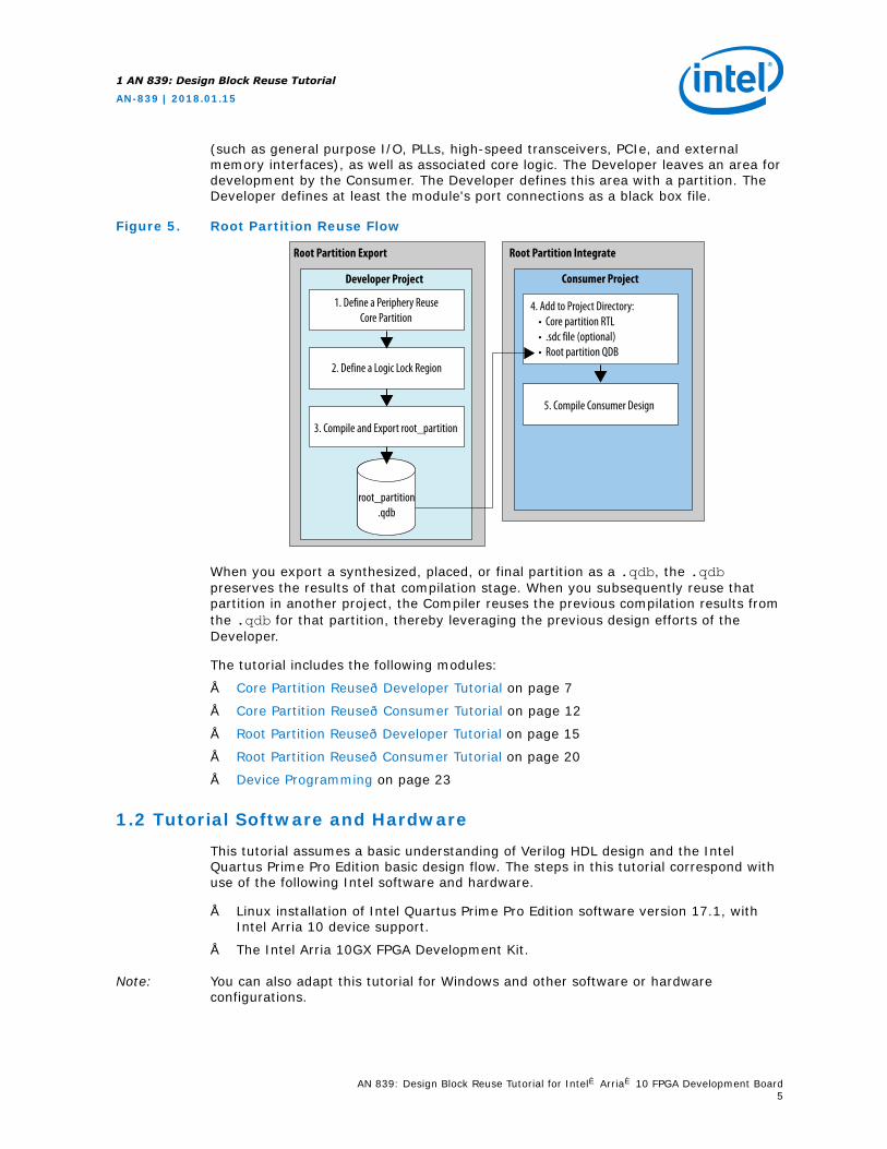
(such as general purpose I/O, PLLs, high-speed transceivers, PCIe, and externalmemory interfaces), as well as associated core logic. The Developer leaves an area fordevelopment by the Consumer. The Developer defines this area with a partition. TheDeveloper defines at least the module's port connections as a black box file.
Figure 5. Root Partition Reuse Flow
root_partition.qdb
3. Compile and Export root_partition
4. Add to Project Directory: • Core partition RTL • .sdc file (optional) • Root partition QDB
Developer Project Consumer Project
Root Partition Export Root Partition Integrate
1. Define a Periphery ReuseCore Partition
2. Define a Logic Lock Region
5. Compile Consumer Design
When you export a synthesized, placed, or final partition as a .qdb, the .qdbpreserves the results of that compilation stage. When you subsequently reuse thatpartition in another project, the Compiler reuses the previous compilation results fromthe .qdb for that partition, thereby leveraging the previous design efforts of theDeveloper.
The tutorial includes the following modules:
• Core Partition Reuse—Developer Tutorial on page 7
• Core Partition Reuse—Consumer Tutorial on page 12
• Root Partition Reuse—Developer Tutorial on page 15
• Root Partition Reuse—Consumer Tutorial on page 20
• Device Programming on page 23
1.2 Tutorial Software and Hardware
This tutorial assumes a basic understanding of Verilog HDL design and the IntelQuartus Prime Pro Edition basic design flow. The steps in this tutorial correspond withuse of the following Intel software and hardware.
• Linux installation of Intel Quartus Prime Pro Edition software version 17.1, withIntel Arria 10 device support.
• The Intel Arria 10GX FPGA Development Kit.
Note: You can also adapt this tutorial for Windows and other software or hardwareconfigurations.
1 AN 839: Design Block Reuse Tutorial
AN-839 | 2018.01.15
AN 839: Design Block Reuse Tutorial for Intel® Arria® 10 FPGA Development Board5

Related Links
• Block-Based Design FlowsFor general information about all block-based flows
• Intel Quartus Prime Pro Edition Foundation Online TrainingFor training on Intel Quartus Prime Pro Edition basics
1.3 Tutorial Files
This tutorial includes a design example organized into directories that correspond withthe flow (Core or Root partition reuse) and role (Developer or Consumer).
Figure 6. Tutorial Directory Structure
Core_Partition_Reuse
Completed
Consumer
Developer
Script
Consumer
Script
Developer
Root_Partition_Reuse
Completed
Consumer
Developer
Script
Consumer
Script
Developer
The Completed directories contain the final versions of all the files required tocomplete that tutorial module. You can use the files in the Completed directories tobypass tutorial steps, or skip to the final step of the tutorial module. The Scriptdirectories contain scripts to automatically run the flows that each module describes.
Follow these steps to use the design example files with this tutorial:
1. Locate and download the design reuse tutorial design files at:
https://www.altera.com/content/dam/altera-www/global/en_US/others/literature/tt/q171_design_block_reuse_tutorial.zip
2. Unzip the q171_design_block_reuse_tutorial.zip file.
The .zip includes the following subdirectories that extract to theq171_design_block_reuse_tutorial directory.
Table 1. Tutorial Design Example Files
Directory Name Description
Core_Partition_Reuse/Developer/ Contains the source files for completing the core partition reuseDeveloper tutorial steps.
Core_Partition_Reuse/Consumer/ Contains the source files for completing the core partition reuseConsumer tutorial steps.
Core_Partition_Reuse/Completed/ Contains final versions of all the files to complete the core partitionreuse tutorial module.
continued...
1 AN 839: Design Block Reuse Tutorial
AN-839 | 2018.01.15
AN 839: Design Block Reuse Tutorial for Intel® Arria® 10 FPGA Development Board6

Directory Name Description
Root_Partition_Reuse/Developer/ Contains the files for completing the root partition reuse Developertutorial steps.
Root_Partition_Reuse/Consumer/ Contains the files for completing the root partition reuse Consumertutorial steps.
Root_Partition_Reuse/Completed/ Contains final versions of all the files to complete the core partitionreuse tutorial step.
• */Developer/Scripts
• */Consumer/Scripts
The Consumer and Developer directories contain Scriptssubdirectories that include the following helpful scripts:• Scripts/run.sh—automatically completes all steps for that
flow.• Scripts/restore.sh—restores the tutorial files for that flow
to default state.You must run these scripts from the project directory in the form ofScripts/run.sh. The Intel Quartus Prime Pro Edition executablemust by in your system path.
1.4 Core Partition Reuse—Developer Tutorial
Follow the steps in this tutorial module to develop a core partition for reuse in aConsumer project.
Process Description
As an IP Developer, you define, place, route, and eventually export a block of codewithin a partition. You then pass the exported .qdb to a Consumer.
Exporting a .qdb file also requires that you provide a black box file to the Consumer.The black box file defines the ports and port interface types for synthesis in theConsumer project. The Compiler ignores any further RTL that you include in the blackbox file.
You add the black box file to the Consumer project as a source file. You assign theexported .qdb file to a partition in the Consumer design. The .qdb file contains all ofthe information from the Developer's compilation snapshot. The Consumer can thenreuse these compilation results in the Consumer reuses the partition. The synthesissnapshot includes only synthesis results, and contains no placement and routinginformation. Similarly, the place snapshot does not include routing information. Onlythe final snapshot includes synthesis, placement, and routing results.
Completed Tutorial Files
The Core_Partition_Reuse/Completed/Developer/ tutorial directory containsthe completed files for this tutorial module.
1 AN 839: Design Block Reuse Tutorial
AN-839 | 2018.01.15
AN 839: Design Block Reuse Tutorial for Intel® Arria® 10 FPGA Development Board7

Tutorial Steps
This tutorial module includes the following steps:
• Step 1: Define a Core Partition on page 8
• Step 2: Compile and Export the Core Partition on page 9
• Step 3: Create the Black Box File on page 10
• Step 4: Copy Files to Consumer Project on page 11
• Step 5: Hardware Verification (Optional) on page 11
Command-Line Alternative Step
You can skip Step 1: Define a Core Partition on page 8 and Step 2: Compile andExport the Core Partition on page 9 in this tutorial module by adding the followingline to the Intel Quartus Prime Settings file (.qsf), and then running theCore_Partition_Reuse/Developer/Script/run.sh script.
set_instance_assignment -name PARTITION blinking_led \ -to u_blinking_led -entity top
1.4.1 Step 1: Define a Core Partition
Follow these steps to open the top.qpf tutorial project in the Intel Quartus Prime ProEdition software, run design synthesis, and define a design partition for core logic.
1. In the Intel Quartus Prime Pro Edition software, click File ➤ Open Project andopen the /Core_Partition_Reuse/Developer/top.qpf project file.
2. To synthesize the design, click Analysis & Synthesis on the CompilationDashboard. The Compilation dashboard displays a check mark when synthesis iscomplete.
3. In the Project Navigator, right-click the u_blinking_led instance in the Hierarchytab, and then click Design Partition ➤ Set as Design Partition. A designpartition icon appears next to each instance you assign.
1 AN 839: Design Block Reuse Tutorial
AN-839 | 2018.01.15
AN 839: Design Block Reuse Tutorial for Intel® Arria® 10 FPGA Development Board8

4. To view and edit all design partitions in the project, click Assignments ➤ DesignPartitions Window. You can also define new partitions in this window.
1.4.2 Step 2: Compile and Export the Core Partition
Follow this step to run full compilation and export a final snapshot of your corepartition. After compilation, you can export the core partition at the synthesized,placed, or final stage. This tutorial reuses the final snapshot. You can then reuse thecore partition in the same project or in another project.
1. To run full compilation of the design and create the final snapshot, click CompileDesign on the Compilation Dashboard. Check marks indicate when each stage ofcompilation is complete.
2. To export the core partition, click Project ➤ Export Design Partition. Selectblinking_led for the Partition name, and the final compilation Snapshot forexport.
1 AN 839: Design Block Reuse Tutorial
AN-839 | 2018.01.15
AN 839: Design Block Reuse Tutorial for Intel® Arria® 10 FPGA Development Board9

3. Confirm blinking_led.qdb as the Partition Database File name, and thenclick OK. The final blinking_led.qdb that you export preserves the completeplacement and routing information from the original project when you reuse theblock in a Consumer project.
1.4.3 Step 3: Create the Black Box File
Integrating a core partition .qdb into another project requires that you add asupporting black box file to the Consumer project. The black box file defines the portsand port interface types for the block that you reuse in the Consumer project. Followthese steps to create a black box port definitions file for the blinking_led partition.
1. To create a new text file, click File ➤ New, select SystemVerilog HDL File underDesign Files, and then click OK. Create a file that contains only the portdefinitions for the partition you export. These are the same port definitions thatthe blinking_led.v file specifies:
module blinking_led ( output [3:0] value, input clock );
endmodule
2. Save the black box file as blinking_led_bb.sv. When saving this file, disablethe option to Add file to current project.
1 AN 839: Design Block Reuse Tutorial
AN-839 | 2018.01.15
AN 839: Design Block Reuse Tutorial for Intel® Arria® 10 FPGA Development Board10

1.4.4 Step 4: Copy Files to Consumer Project
After exporting the core partition and creating the black box file, you copy the files tothe Consumer project directory for subsequent use in the Core Partition Reuse—Consumer Tutorial on page 12.
Manually copy the blinking_led.qdb and blinking_led_bb.sv files to theCore_Partition_Reuse/Consumer/ directory.
Note: There is no requirement to pass an .sdc file for the partition to the Consumer project,because the .sdc does not influence the logic, placement, or routing of a finalizedpartition in the Consumer project. However, the Developer can optionally providean .sdc file for the partition to the Consumer project for timing analysis of thepartition after complete integration with the Consumer design.
In the Core Partition Reuse—Consumer Tutorial on page 12, you integrate theblinking_led.qdb and blinking_led_bb.sv files into the Consumer project.
1.4.5 Step 5: Hardware Verification (Optional)
You can now optionally verify the results of the Core Partition Reuse—Developertutorial module in hardware by completing Device Programming on page 23.
After completing this tutorial module, LEDs D6-D3 map to the blinking_led core,and LEDs D10-D7 map to the top-level design. After you configure the FPGA with theSRAM Object File (.sof), the blinking_led core flashes red LEDs in a binarycounting order. The top-level design does not illuminate any LEDs.
Figure 7. Illumination of LEDs After Core Partition Reuse—Developer Tutorial Module
Off Counting
D10-D7 D6-D3
1 AN 839: Design Block Reuse Tutorial
AN-839 | 2018.01.15
AN 839: Design Block Reuse Tutorial for Intel® Arria® 10 FPGA Development Board11

1.5 Core Partition Reuse—Consumer Tutorial
Follow the steps in this tutorial module to reuse a core partition in a Consumerproject.
Process Description
As a core partition Consumer, you receive the final core partition that the Developerprovides. The Consumer adds the black box file and assigns the .qdb in the Consumerproject. Because the exported .qdb includes compiled netlist information, theConsumer project must target the same FPGA device part number, and use the sameIntel Quartus Prime version as the Developer project.
The Consumer must specify all signals and port directions, as well as any Verilog HDLparameters or VHDL generics. The Developer can optionally include an .sdc for thepartition to verify the partition timing results after full integration in the Consumerproject.
Completed Tutorial Files
The Core_Partition_Reuse/Completed/Consumer/ tutorial directory containsthe completed files for this tutorial module.
Tutorial Module Steps
This tutorial module includes the following steps:
• Step 1: Add Files and Run Synthesis on page 12
• Step 2: Create a Partition for blinking_led on page 13
• Step 3: Compile the Design on page 13
• Step 4: Hardware Verification (Optional) on page 14
Command-Line Alternative Tutorial Step
You can skip Step 1: Add Files and Run Synthesis on page 12 through Step 3:Compile the Design on page 13 in this tutorial module by adding the following linesto the .qsf, and then running the Core_Partition_Reuse/Consumer/Script/run.sh script.
#Create the partitionset_instance_assignment -name PARTITION blinking_led \ -to u_blinking_led -entity top#Assign the .qdb file to the partitionset_instance_assignment -name QDB_FILE_PARTITION blinking_led.qdb \ -to u_blinking_led -entity top#Add the BB file to the file listset_global_assignment -name SYSTEMVERILOG_FILE blinking_led_bb.sv
1.5.1 Step 1: Add Files and Run Synthesis
To add the core partition to the Consumer project, add the black box as a source file inthe project, and assign the core partition .qdb to an instance in the Design PartitionsWindow, as the following steps describe:
1 AN 839: Design Block Reuse Tutorial
AN-839 | 2018.01.15
AN 839: Design Block Reuse Tutorial for Intel® Arria® 10 FPGA Development Board12

1. In the Intel Quartus Prime Pro Edition software, click File ➤ Open Project andopen the /Core_Partition_Reuse/Consumer/top.qpf project file.
2. To add files to the project, click Project ➤ Add/Remove Files in Project.
3. On the Files pane, click the browse (...) button near File name to locate andselect the /Core_Partition_Reuse/Consumer/blinking_led_bb.sv blackbox file. Click Open, and then click OK. The file is now a source file in the project.
4. To synthesize the design, click Analysis & Synthesis on the CompilationDashboard. The Compilation dashboard displays a check mark when synthesis iscomplete.
1.5.2 Step 2: Create a Partition for blinking_led
Follow these steps to create a partition for blinking_led.
1. In the Project Navigator, right-click the u_blinking_led instance in the Hierarchytab, and then click Design Partition ➤ Set as Design Partition. A designpartition icon appears next to each instance you assign.
2. To assign the blinking_led.qdb to the partition, click Assignments ➤ DesignPartitions Window.
3. Double-click in the Partition Database File cell, and then click browse (...) toselect the blinking_led.qdb from the Developer project.
Figure 8. qdb Assignment in Design Partitions Window
1.5.3 Step 3: Compile the Design
After creating a partition for blinking_led, you are ready to run a full compilation ofthe design.
1. To run a full compilation, click Compile Design on the Compilation Dashboard.
2. View the results of compilation in the Compilation Report.
1 AN 839: Design Block Reuse Tutorial
AN-839 | 2018.01.15
AN 839: Design Block Reuse Tutorial for Intel® Arria® 10 FPGA Development Board13

After you complete these steps, the project uses the blinking_led.qdb file as asource, in place of the RTL. The placement and routing from the previous partitionexport is preserved. The logic in the top-level design is synthesized, placed, androuted, while preserving the placed and routed blinking_led.qdb partition.
1.5.4 Step 4: Hardware Verification (Optional)
You can now optionally verify the results of the Core Partition Reuse—ConsumerTutorial module in hardware by completing Device Programming on page 23.
After completing this tutorial module, LEDs D6-D3 map to the blinking_led core,and LEDs D10-D7 map to the top-level design. After configuring the FPGA, theblinking_led core flashes red LEDs in a binary counting order. The top-level designshows a shifting bit in green.
Figure 9. Illumination of LEDs After Core Partition Reuse—Consumer Tutorial Module
Shifting Bit Counting
D10-D7 D6-D3
1 AN 839: Design Block Reuse Tutorial
AN-839 | 2018.01.15
AN 839: Design Block Reuse Tutorial for Intel® Arria® 10 FPGA Development Board14

1.6 Root Partition Reuse—Developer Tutorial
Follow the steps in this tutorial module to develop a root partition for reuse.
Process Description
As a root partition Developer, you create, compile, and eventually export a top-levelroot partition that includes the device periphery. The Developer also defines aperiphery reuse core partition for subsequent development of core logic in theConsumer project. The Developer fully compiles this design and then provides the rootpartition .qdb and an .sdc file for the top-level design.
Figure 10. Root Partition Reuse Flow
SynthesisFitter
TimingExport
RTL
SOFQDB
RTL
SynthesisFitter
TimingAssembler
Programmer
Root Partition (Periphery)
top Revision
Consumer - Project Integration
full_designRevision
Figure 11. Periphery Reuse Core Partition "Hole" for Consumer's Core Logic
Root Partition(periphery I/O, HSSIO, PLL, PCIe*, PLL, Configuration, Routing, Clocking Core logic)
Core Partition(LUT, FF RAM, DSP,
Routing)
The following figure shows the Developer's root partition with a placeholder for theblinking_led module. For this tutorial, blinking_led simply ties the outputs to4’b1111 to turn off the LEDs.
Figure 12. RTL View of Developer's Root Partition
1 AN 839: Design Block Reuse Tutorial
AN-839 | 2018.01.15
AN 839: Design Block Reuse Tutorial for Intel® Arria® 10 FPGA Development Board15

Completed Tutorial Files
The Root_Partition_Reuse/Completed/Developer/ tutorial directory containsthe completed files for this tutorial module.
Tutorial Module Steps
This tutorial module includes the following steps:
• Step 1: Create a Periphery Reuse Core Partition on page 16
• Step 2: Define a Logic Lock Region on page 17
• Step 3: Compile and Export the Root Partition on page 18
• Step 4: Copy Files to Consumer Project on page 11
• Step 5: Hardware Verification (Optional) on page 19
Command-Line Alternative Tutorial Step
You can skip Step 1: Create a Periphery Reuse Core Partition on page 16 through Step 3: Compile and Export the Root Partition on page 18 in this tutorial module byadding the following lines to the .qsf, and then running theRoot_Partition_Reuse/Developer/Script/run.sh script.
set_instance_assignment -name PARTITION blinking_led \ -to u_blinking_led -entity topset_instance_assignment -name PERIPHERY_REUSE_CORE ON -to \ u_blinking_led -entity topset_instance_assignment -name PLACE_REGION \ "X63 Y102 X185 Y162" -to u_blinking_ledset_instance_assignment -name RESERVE_PLACE_REGION ON -to \ u_blinking_ledset_instance_assignment -name CORE_ONLY_PLACE_REGION ON \ -to u_blinking_ledset_instance_assignment -name REGION_NAME u_blinking_led -to \ u_blinking_ledset_instance_assignment -name ROUTE_REGION \ "X63 Y102 X185 Y162" -to u_blinking_led
1.6.1 Step 1: Create a Periphery Reuse Core Partition
To export and reuse the root partition, first create a periphery reuse core partition forsubsequent core logic development in the Consumer project.
1. In the Intel Quartus Prime Pro Edition software, click File ➤ Open Project andopen the /Root_Partition_Reuse/Developer/top.qpf project file.
2. To synthesize the design, click Analysis & Synthesis on the CompilationDashboard.
3. In the Project Navigator, right-click the u_blinking_led instance in the Hierarchytab, and then click Design Partition ➤ Set as Design Partition.
4. To change the partition type, click Assignments ➤ Design Partitions Window.
5. For the partition Type, select Periphery Reuse Core.
1 AN 839: Design Block Reuse Tutorial
AN-839 | 2018.01.15
AN 839: Design Block Reuse Tutorial for Intel® Arria® 10 FPGA Development Board16

Figure 13. Periphery Reuse Core Partition Type
1.6.2 Step 2: Define a Logic Lock Region
You must define a core-only, reserved, fixed routing region to reserve core resourcesin the Consumer project for the periphery reuse core partition. The Consumer usesthis area for core logic development.
Ensure that the exclusive placement region size is large enough to contain all corelogic in the partition. For projects with multiple core partitions, constrain each partitionin a non-overlapping placement or routing region. Follow these steps to define a core-only, reserved, fixed routing region to reserve core resources in the Developer projectfor non-periphery development:
1. Right-click the u_blinking_led instance in the Project Navigator and clickLogic Lock Region ➤ Create New Logic Lock Region.
2. To modify the region properties, click Assignments ➤ Logic Lock RegionsWindow.
3. In the Origin column, specify X63_Y102.
4. Change the Width to 123, and the Height to 61.
5. Enable the Reserved and Core-Only options.
6. Click the Routing Region cell. The Logic Lock Routing Region Settings dialogbox appears.
7. Specify Fixed with expansion with Expansion Length of 0 for the RoutingType. The actual size and location are arbitrary for this tutorial. However, you canview and adjust the Logic Lock Region shape in the Chip Planner.
8. In the Logic Lock Regions window, right-click the u_blinking_led Logic Lockregion name, and then click Locate Node ➤ Locate in Chip Planner.
1 AN 839: Design Block Reuse Tutorial
AN-839 | 2018.01.15
AN 839: Design Block Reuse Tutorial for Intel® Arria® 10 FPGA Development Board17

The Logic Lock region is shaded in purple. Preserving the periphery requires exportingeverything outside the Logic Lock region. This is the reverse of the core partition reuseflow.
1.6.3 Step 3: Compile and Export the Root Partition
After compilation, you can export the root partition at the synthesized, placed, or finalstage. This tutorial reuses the final snapshot.
Follow these steps to compile the design and export the root partition:
1. To run full compilation, click Compile Design on the Compilation Dashboard.
2. To export the root partition to a .qdb file, click Project ➤ Export DesignPartition. Select the root_partition and the final snapshot.
1 AN 839: Design Block Reuse Tutorial
AN-839 | 2018.01.15
AN 839: Design Block Reuse Tutorial for Intel® Arria® 10 FPGA Development Board18

1.6.4 Step 4: Copy Files to Consumer Project
Manually copy the root_partition.qdb and top.sdc files to theRoot_Partition_Reuse/Consumer/ directory.
Note: The top-level design requires .sdc constraints. The Consumer can also include aseparate .sdc file to constrain the logic that they provide. The Logic Lock boundary isvisible in the Chip Planner in the Consumer project for reference only. The Consumercannot modify this region.
In the Root Partition Reuse—Consumer Tutorial on page 20, you integrate theroot_partition.qdb and top.sdc files into the Consumer project.
1.6.5 Step 5: Hardware Verification (Optional)
You can now verify the results of the Root Partition Reuse—Developer Tutorial modulein hardware by completing the steps in Device Programming on page 23.
After completing this tutorial module, LEDs D6-D3 map to the blinking_led core,and LEDs D10-D7 map to the top-level (root) design. When you create and loadthe .sof, the blinking_led core does not illuminate any LEDs. The top-level designshows a shifting bit in green.
The behavior of the periphery LED driver carries into the Consumer project via thefinal .qdb file.
Figure 14. Illumination of LEDs after the Root Partition Reuse—Developer Tutorial
Shifting Bit Off
D10-D7 D6-D3
1 AN 839: Design Block Reuse Tutorial
AN-839 | 2018.01.15
AN 839: Design Block Reuse Tutorial for Intel® Arria® 10 FPGA Development Board19

1.7 Root Partition Reuse—Consumer Tutorial
Follow the steps in this tutorial module to reuse a root partition in a Consumer project.
Process Description
As a root partition Consumer, you receive the final top-level, placed, and routed rootpartition from the Developer. The Developer includes an empty region in the partitionfor subsequent development in the Consumer project. The Consumer completes thefinal design by adding the root partition and integrating with Consumer logic.
The following figure shows the RTL view of the Consumer's blinking_led partition.The Developer compiles and exports the final snapshot as a .qdb file. The Consumeradds their own logic to the space the Developer reserves.
Figure 15. Consumer's RTL View of blinking_led Partition
Finally, the Consumer integrates their logic with the files from the Developer to createthe final image.
Figure 16. RTL View of the Integrated Developer and Consumer Partitions
Since the root partition .qdb includes final placement and routing information for thepartition, the placement and routing is identical in the Consumer project, with theexception of clock signals that may be global signals.
Completed Files
The Root_Partition_Reuse/Completed/Consumer/ tutorial directory containsthe completed files for this tutorial module.
1 AN 839: Design Block Reuse Tutorial
AN-839 | 2018.01.15
AN 839: Design Block Reuse Tutorial for Intel® Arria® 10 FPGA Development Board20

Tutorial Module Steps
This tutorial module includes the following steps:
• Step 1: Add the SDC and Root Partition on page 21
• Step 2: Compile the Design on page 21
• Step 3: Hardware Verification (Optional) on page 22
Command-Line Alternative Tutorial Step
You can skip Step 1: Add the SDC and Root Partition on page 21 through Step 2:Compile the Design on page 21 in this tutorial module by adding the following linesto the .qsf, and then running the Root_Partition_Reuse/Consumer/Script/run.sh script.
set_global_assignment -name SDC_FILE top.sdc
set_instance_assignment -name QDB_FILE_PARTITION \ root_partition.qdb -to | -entity top
1.7.1 Step 1: Add the SDC and Root Partition
Follow these steps to add the .sdc file and the root partition to the Consumer project.
1. In the Intel Quartus Prime Pro Edition software, click File ➤ Open Project andopen the /Root_Partition_Reuse/Consumer/top.qpf project file.
2. To add the .sdc file to the project, click Project ➤ Add/Remove Files inProject.
3. On the Files pane, click the browse (...) button near File name to locate andselect the top.sdc file. Click Open, and then click OK.
4. To add the root partition .qdb to the Consumer project, click Assignments ➤Settings, and then click the General page.
5. Enable This project uses a Partition Database (.qdb) file for the rootpartition, and then select root_partition.qdb as the Root Partition Databasefile.
6. Reset the Top-level entity setting to Top. Click Apply, then click OK.
1.7.2 Step 2: Compile the Design
After adding the .sdc and root partition to the Consumer project, you are ready to runa full compilation of the design.
1 AN 839: Design Block Reuse Tutorial
AN-839 | 2018.01.15
AN 839: Design Block Reuse Tutorial for Intel® Arria® 10 FPGA Development Board21

1. To run full compilation, click Compile Design on the Compilation Dashboard.
2. View the results of compilation in the Compilation Report.
1.7.3 Step 3: Hardware Verification (Optional)
You can now verify the results of the Root Partition Reuse—Consumer Tutorial modulein hardware by completing the steps in Device Programming on page 23.
After completing this tutorial module, LEDs D6-D3 map to the blinking_led core,and LEDs D10-D7 map to the top-level design. The blinking_led core flashes redLEDs in a binary counting order. The top-level design shows a single bit shifting ingreen.
Figure 17. Illumination of LEDs after the Root Partition Reuse—Consumer Tutorial
Shifting Bit Counting
D10-D7 D6-D3
1 AN 839: Design Block Reuse Tutorial
AN-839 | 2018.01.15
AN 839: Design Block Reuse Tutorial for Intel® Arria® 10 FPGA Development Board22

1.8 Device Programming
After completing any of the tutorial modules, you can optionally configure the FPGA onthe Intel Arria 10 GX Development Kit to verify the results in hardware. You can adaptthe following steps if you are using a different device or development kit. Configuringthe FPGA involves opening the Intel Quartus Prime Pro Edition Programmer,connecting to the Development Kit board, and loading the configuration SRAM ObjectFile (.sof) into the SRAM of the FPGA.
Note: A .sof file configures the SRAM of an Intel FPGA. A Programmer Object File (.pof)programs a flash memory device with an FPGA configuration image for subsequentloading to an FPGA.
Follow these steps to configure the FPGA on the Intel Arria 10 GX Development Kit:
1. To open the Intel Quartus Prime Programmer, click Tools ➤ Programmer.
2. Connect the board cables:
• JTAG USB cable to board
• Power cable attached to board and power source.
3. Turn on power to the board.
4. In the Intel Quartus Prime Programmer, click Hardware Setup.
5. In the Hardware list, select USB-BlasterII, and then click Close. The devicechain appears.
Note: If the device chain does not appear, verify the board connections.
6. Click Auto-Detect. The device chain populates.
7. In the Found Devices list, select the device that matches your design and clickOK. For this tutorial, select the 10AX115S2 device that matches the10AX115S2F45I1SG FPGA on the Intel Arria 10 GX Development Kit.
8. Right-click the 10AX115S2 row in the file list, and then click Change File.
1 AN 839: Design Block Reuse Tutorial
AN-839 | 2018.01.15
AN 839: Design Block Reuse Tutorial for Intel® Arria® 10 FPGA Development Board23

9. Browse to select the top.sof file from the appropriate tutorial/<core orroot>/<developer or consumer>/ directory.
10. Enable the Program/Configure option for the 10AX115S2 row.
11. Click Start. The progress bar reaches 100% when device configuration iscomplete. The device is now fully configured and in operation.
Note: If device configuration fails, make sure the device you select forconfiguration matches the device you specify during .sof file generation.
1 AN 839: Design Block Reuse Tutorial
AN-839 | 2018.01.15
AN 839: Design Block Reuse Tutorial for Intel® Arria® 10 FPGA Development Board24

1.9 Document Revision History
This document has the following revision history:
Table 2. Document Revision History
Document Version Software Version Changes
2018.01.15 17.1.0 Initial release of the document.
1 AN 839: Design Block Reuse Tutorial
AN-839 | 2018.01.15
AN 839: Design Block Reuse Tutorial for Intel® Arria® 10 FPGA Development Board25