ams 9420 wireless vibration transmitter - emerson …...c sensor 2 signal white wire d sensor common...
TRANSCRIPT

Quick Start GuideMHM-97409, Rev 11
May 2019
AMS 9420 Wireless VibrationTransmitter
Quick Start Guide

Copyright
© 2019 by Emerson. All rights reserved.
No part of this publication may be reproduced, transmitted, transcribed, stored in a retrievalsystem, or translated into any language in any form by any means without the written permissionof Emerson.
Disclaimer
This manual is provided for informational purposes. EMERSON MAKES NO WARRANTY OF ANYKIND WITH REGARD TO THIS MATERIAL, INCLUDING, BUT NOT LIMITED TO, THE IMPLIEDWARRANTIES OF MERCHANTABILITY AND FITNESS FOR A PARTICULAR PURPOSE. Emerson shallnot be liable for errors, omissions, or inconsistencies that may be contained herein or forincidental or consequential damages in connection with the furnishing, performance, or use ofthis material. Information in this document is subject to change without notice and does notrepresent a commitment on the part of Emerson. The information in this manual is not all-inclusive and cannot cover all unique situations.
Patents
The product(s) described in this manual are covered under existing and pending patents.
Quick Start Guide May 2019
2 MHM-97409, Rev 11

Safety messages
Instructions in this manual may require special precautions to ensure the safety of the personnelperforming the operations.
This AMS 9420 device complies with Part 15 of the FCC Rules. Operation is subject to thefollowing conditions: This device may not cause harmful interference, this device must accept anyinterference received, including interference that may cause undesired operation.
This device must be installed to ensure a minimum antenna separation of 20 cm from all persons.
Refer to the following safety messages before performing an operation preceded by the warningsymbol:
WARNING!
Failure to follow these installation guidelines can result in death or serious injury. Only qualifiedpersonnel should install AMS 9420s.
Explosions could result in death or serious injury:
• Before connecting a Field Communicator in an explosive environment, make sure the instrumentsare installed in accordance with applicable field wiring practices.
• Verify that the operating environment of the AMS 9420 is consistent with the appropriatehazardous locations certifications.
• Do not remove the front electronics end cap or LCD cover while the device is in a hazardous area.
Electrical shock can cause death or serious injury. Avoid contact with the leads and terminals. Highvoltage that may be present on leads can cause electrical shock.
ContentsIntroduction ................................................. 4
Install the AMS 9420 ..................................... 6
Join the AMS 9420 to a wirelessnetwork ...................................................... 12
Verify the device is operational ................... 15
Installing required ferrites ...........................18
Shipping considerations for wireless products(Lithium Batteries) ...................................... 21
Troubleshooting ......................................... 22
Product certifications ..................................23
Quick Start Guide May 2019
3 MHM-97409, Rev 11
1 Introduction
This Quick Start Guide applies to the 2.4 GHz WirelessHART™ version of the AMS 9420. It describes a typical installation with standard low-powered sensors (25 mV/g) and a power module.
This document includes basic guidelines for the AMS 9420 Wireless Vibration Transmitter. It does not provide instructions for detailed configuration, diagnostics, maintenance, or service. The AMS 9420 Wireless Vibration Transmitter Reference Manual (part number MHM-97408) contains more instructions, and other sensor and power options. A digital version of this document is available on the Emerson website, http://www.emerson.com/en-us/catalog/ams-a9420.
The term "sensor" applies to both an accelerometer and an accelerometer with embedded temperature; the word “accelerometer” refers to a sensor that measures only acceleration.
The transmitter's main parts are shown in Figure 1-1.
Quick Start Guide May 2019
4 MHM-97409, Rev 11
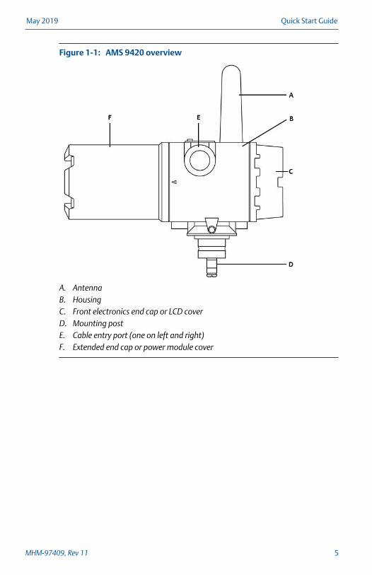
AMS 9420 overviewFigure 1-1:
A. AntennaB. HousingC. Front electronics end cap or LCD coverD. Mounting postE. Cable entry port (one on left and right)F. Extended end cap or power module cover
May 2019 Quick Start Guide
MHM-97409, Rev 11 5
2 Install the AMS 9420
Before beginning installation procedures:
Insert the power module only when you are ready to commission the device.
Install the Emerson Wireless Gateway and ensure it functions properly beforeyou activate the AMS 9420 or any other wireless devices. Power up wirelessdevices in order of proximity from the Emerson Wireless Gateway, beginningwith the closest. This will result in a simpler and faster network installation.
WARNING!
If the sensor is installed in a high-voltage environment and a fault conditionor installation error occurs, the sensor leads and transmitter terminals couldcarry lethal voltages. Use extreme caution when making contact with theleads and terminals.
2.1 Prepare sensors for use with the AMS 9420
This procedure describes installing the AMS 9420 with standard low-poweredsensors (25 mV/g nominal sensitivity). See the Reference Manual forinformation about other options such as using ICP accelerometers (100 mV/gnominal sensitivity).
Procedure
1. Install sensors according to standard sensor installation practices. Usethread sealant on all connections.
See the Reference Manual for detailed sensor mounting instructions.
NoteThe AMS 9420 uses special low-power sensors (available for purchasefrom Emerson) to reduce power consumption and increase powermodule life.
2. Run wiring (and conduit, if necessary) from the sensor to the AMS 9420.
The AMS 9420 is not approved for use with a cable that is 30 m (100 ft) orlonger. The recommended maximum cable length is 29 m (95 ft). Shorteris better.
If your cable is longer than 3 meters, you must attach ferrites at the AMS9420 end of the cable. For armored cables, add ferrites before attachingsensor wires to the transmitter. For standard cables, add the ferrites afterattaching the sensor wires to the transmitter. See page 18.
Quick Start Guide May 2019
6 MHM-97409, Rev 11
3. Pull the wiring through the threaded conduit entry of the AMS 9420. Ifyou are not using conduit, use an appropriate grommet or cable-gland toprovide both strain relief for the cable and environmental isolation for theAMS 9420.
2.2 Attach sensor wiring to the AMS 9420 terminals
Prerequisites
• If you are using armor-jacketed cable longer than 3 meters, you mustattach the ferrites before attaching sensor wiring the AMS 9420terminals. See Section 5.2.
• If the sensor signal wires are not equipped with spade lugs, Emersonrecommends installing them before proceeding.
Procedure
1. Tie the sensor's grounding wire (white with black stripe) to the groundscrew inside the AMS 9420.
See callout E in the figures below.
2. Refer to the appropriate figure to connect the sensor signal wires.
NoteYou can connect one or two accelerometers to the AMS 9420. You canconnect only one accelerometer with a temperature sensor.
a. Insert a beryllium copper washer on top of each spade lug.
b. Tighten the screw to 15 in-lbs (1.7 N-m).
May 2019 Quick Start Guide
MHM-97409, Rev 11 7

AMS 9420 wiring with one accelerometerFigure 2-1:
A Sensor power Red wire
B Sensor signal White wire
C Unused Unused
D Sensor common Black wire
E Sensor grounding White wire with black stripe
Quick Start Guide May 2019
8 MHM-97409, Rev 11
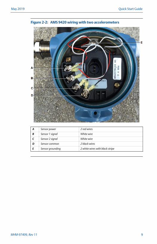
AMS 9420 wiring with two accelerometersFigure 2-2:
A Sensor power 2 red wires
B Sensor 1 signal White wire
C Sensor 2 signal White wire
D Sensor common 2 black wires
E Sensor grounding 2 white wires with black stripe
May 2019 Quick Start Guide
MHM-97409, Rev 11 9
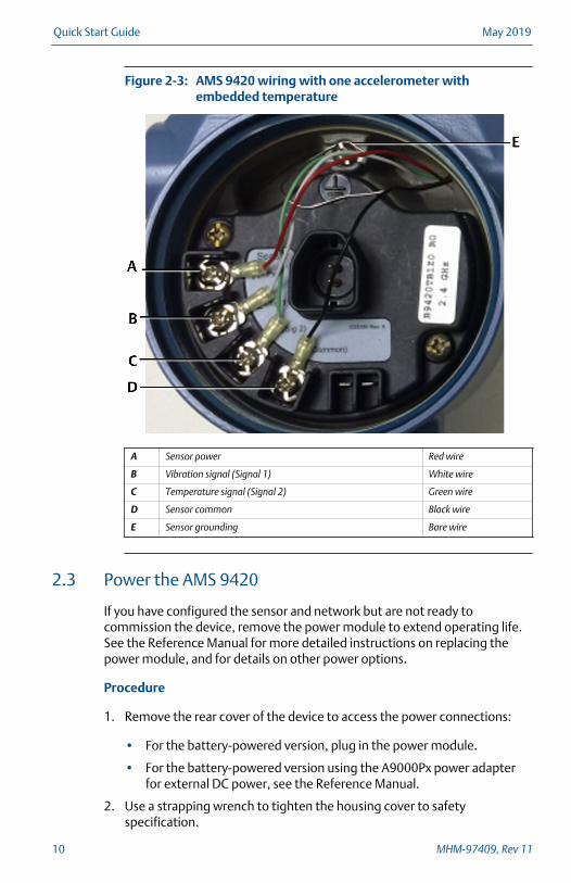
AMS 9420 wiring with one accelerometer withembedded temperature
Figure 2-3:
A Sensor power Red wire
B Vibration signal (Signal 1) White wire
C Temperature signal (Signal 2) Green wire
D Sensor common Black wire
E Sensor grounding Bare wire
2.3 Power the AMS 9420
If you have configured the sensor and network but are not ready tocommission the device, remove the power module to extend operating life.See the Reference Manual for more detailed instructions on replacing thepower module, and for details on other power options.
Procedure
1. Remove the rear cover of the device to access the power connections:
• For the battery-powered version, plug in the power module.
• For the battery-powered version using the A9000Px power adapterfor external DC power, see the Reference Manual.
2. Use a strapping wrench to tighten the housing cover to safetyspecification.
Quick Start Guide May 2019
10 MHM-97409, Rev 11
Always ensure a proper seal by installing the housing cover so that metaltouches metal and the black O-ring is no longer visible, but do not overtighten. A tight seal ensures that water, water vapor, or other gases donot penetrate into the housing.
3. Position the antenna so it points upward, for optimal performance.
May 2019 Quick Start Guide
MHM-97409, Rev 11 11

3 Join the AMS 9420 to a wireless network
3.1 Join the AMS 9420 to a network using AMS DeviceManager
Prerequisites
Configure the Emerson Wireless Gateway in the AMS Device ManagerNetwork Configuration.
Procedure
1. Connect the AMS 9420 to the HART modem.
2. In AMS Device Manager, drag and drop the AMS 9420 on the EmersonWireless Gateway icon.
The AMS 9420 joins the network.
3. Navigate to the Emerson Wireless Gateway and verify the AMS 9420 has acheckmark.
Example:
4. Remove the HART modem.
The AMS 9420 will begin publishing data when the modem is removed.
5. In Device Explorer view or Device Connection view, right-click theEmerson Wireless Gateway icon, and select Rebuild and Identify Hierarchy.
6. Right-click the Emerson Wireless Gateway icon, and select Scan Device.
3.2 Join the AMS 9420 to a network using a FieldCommunicator
This procedure describes using the 475 Field Communicator. For instructionson using the AMS Trex™ Device Communicator, refer to the AMS Trex DeviceCommunicator User Guide.
Prerequisites
If you are connecting a Field Communicator directly to the device, make sureyou are in a location that allows you to remove the AMS 9420 rear cover.
Quick Start Guide May 2019
12 MHM-97409, Rev 11
Procedure
1. With a Field Communicator, connect to the comm terminals on thedevice.
2. Configure the AMS 9420:
Field communicator fast key sequence - configure AMS9420 settings
Table 3-1:
Function Fast key sequences Menu items
Initial Setup 2,1 (Guided Setup) Configure SensorsConfigure Variable MappingConfigure UnitsAlert LimitsSensor Power EnableJoin Device to NetworkConfigure PublishingConfigure Update Rate
Device Setup 2,2,1 (Manual Setup) Network IDBroadcast InfoJoin Device to NetworkConfigure PublishingConfigure Update RateTransmit Power LevelDefault Burst Config
Alert Setup 2,3 (Alert Setup) Overall VelocityPeakVueBiasAmbient TemperatureSupply Voltage
3. Join the AMS 9420 to 2.4 GHz wireless network:
Field Communicator fast key sequence—connect to anetwork
Table 3-2:
Key sequence Menu item
2, 2, 1 (Manual setup) Network IDBroadcast InfoJoin Device to NetworkConfigure PublishingConfigure Update RateTransmit Power LevelDefault Burst Config
May 2019 Quick Start Guide
MHM-97409, Rev 11 13

Field Communicator fast key sequence—connect to anetwork (continued)
Table 3-2:
Key sequence Menu item
2, 1 (Guided setup) Configure SensorsConfigure Variable MappingConfigure UnitsAlert LimitsSensor Power EnableJoin Device to NetworkConfigure PublishingConfigure Update Rate
NoteDisconnect the leads when you are finished configuring ortroubleshooting. The AMS 9420 does not publish any new vibration datato the gateway while connected to an AMS Trex Device Communicator,475 Field Communicator, or HART modem. It can take up to threeminutes for the leads connection to time out; after which, the AMS 9420resumes reporting new readings to the gateway.
4. Remove the Field Communicator and replace the cover. Use a strappingwrench to tighten the housing cover to safety specification.
Always ensure a proper seal by installing the housing cover so that metaltouches metal and the black O-ring is no longer visible, but do not overtighten. A tight seal ensures that water, water vapor, or other gases donot penetrate into the housing.
With the Field Communicator removed, the AMS 9420 begins publishingdata.
Quick Start Guide May 2019
14 MHM-97409, Rev 11
4 Verify the device is operational
You can verify the device operates properly using the following methods:
• Integral LCD (if installed)
• Field Communicator
• Emerson Wireless Gateway web interface
Verify operation with the integral LCD
If the LCD is installed and enabled, it displays a series of start-up screens assoon as you insert the power module.
Verify operation with a 475 Field Communicator
You can verify the status of the device and configure it using a 475 FieldCommunicator. For instructions on using the AMS Trex unit, refer to the AMSTrex Device Communicator User Guide for more information.
Field Communicator fast key sequence—connect to a networkTable 4-1:
Key sequence Menu item
2, 2, 1 (Manual setup) Network IDBroadcast InfoJoin Device to NetworkConfigure PublishingConfigure Update RateTransmit Power LevelDefault Burst Config
2, 1 (Guided setup) Configure SensorsConfigure Variable MappingConfigure UnitsAlert LimitsSensor Power EnableJoin Device to NetworkConfigure PublishingConfigure Update Rate
NoteDisconnect the leads when you are finished configuring or troubleshooting.The AMS 9420 does not publish any new vibration data to the gateway whileconnected to an AMS Trex Device Communicator, 475 Field Communicator,or HART modem. It can take up to three minutes for the leads connection totime out; after which, the AMS 9420 resumes reporting new readings to thegateway.
May 2019 Quick Start Guide
MHM-97409, Rev 11 15

Verify operation with Emerson Wireless Gateway
If the device is configured with the Network ID and Join Key, and sufficienttime for network polling has passed, the transmitter will be connected to thenetwork.
NoteThe time to join a new device to the network is dependent upon the numberof devices being joined and the number of devices in the current network. Forone device joining an existing network with multiple devices, it may take upto five minutes. It may take up to 60 minutes for multiple new devices to jointhe existing network.
1. From the Emerson Wireless Gateway Home page, navigate to the Devicespage.
The Devices page shows if the device has joined the network and if it iscommunicating properly. It also displays the transmitter tag name, PV,SV, TV, QV, time of last update. A checkmark in a green box means thatthe device is working properly. A red indicator means there is a problemwith either the device or its communication path.
NoteIt is normal for the AMS 9420 to have a red “X”, on the screen until thesensor is installed and configured.
Emerson Wireless Gateway Devices pageFigure 4-1:
2. On the Devices page, click + beside a tag name to display moreinformation about the device.
3. Verify the Network ID and Join Key in the device match those found onthe Emerson Wireless Gateway:
Quick Start Guide May 2019
16 MHM-97409, Rev 11

a. From the Emerson Wireless Gateway, click System Settings > Network >Network Settings.
b. Verify Show join key has a check mark.
NoteThe most common cause of incorrect operation is that the Network ID or JoinKey are not set correctly in the device.
May 2019 Quick Start Guide
MHM-97409, Rev 11 17

5 Installing required ferrites
To comply with the CE directive, additional ferrites are required on:
• accelerometer cables longer than 3 meters
• external power cable, when using DC power
NoteThe AMS 9420 is not approved for use with a cable that is 30 m (100 ft) orlonger. The recommended maximum cable length is 29 m (95 ft). Shorter isbetter.
Ferrites required on external DC power cable
AMS 9420s powered with external DC power require ferrites to be installedon the external power cable. For more information about external DC power,see the Reference Manual.
Ferrites required on accelerometer cable
Accelerometer cables longer than 3 meters require additional ferrites to beinstalled at the AMS 9420 end of the cable. The sensor package containsthese additional ferrites. You can attach ferrites to standard cable or armor-jacketed cable.
Emerson ships all low-power sensors used with the AMS 9420 with ferritespre-installed at the accelerometer end. These ferrites maintain the statedperformance of the accelerometer in noisy RF or electrical environments. Donot remove these ferrites.
Ferrites are not required with ferromagnetic conduit
Due to the shielding properties of ferromagnetic conduit, cables installed inferromagnetic conduit (for example, galvanized steel), do not requireadditional ferrites at the AMS 9420 end of the cable.
5.1 Attach 3 ferrites to an accelerometer with standard cable
Use the three ferrites included in the sensor package. Attach them afterinserting the sensor cable through the cable gland and connecting to theAMS 9420.
NoteEmerson recommends that you coil up any excess sensor cable. Do not cutsensor cable.
Quick Start Guide May 2019
18 MHM-97409, Rev 11
Procedure
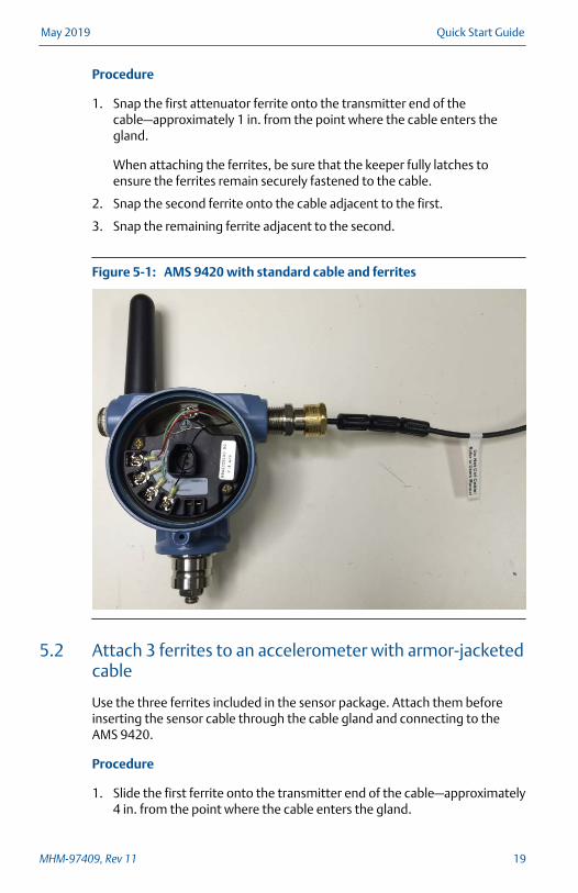
1. Snap the first attenuator ferrite onto the transmitter end of thecable—approximately 1 in. from the point where the cable enters thegland.
When attaching the ferrites, be sure that the keeper fully latches toensure the ferrites remain securely fastened to the cable.
2. Snap the second ferrite onto the cable adjacent to the first.
3. Snap the remaining ferrite adjacent to the second.
AMS 9420 with standard cable and ferritesFigure 5-1:
5.2 Attach 3 ferrites to an accelerometer with armor-jacketedcable
Use the three ferrites included in the sensor package. Attach them beforeinserting the sensor cable through the cable gland and connecting to theAMS 9420.
Procedure
1. Slide the first ferrite onto the transmitter end of the cable—approximately4 in. from the point where the cable enters the gland.
May 2019 Quick Start Guide
MHM-97409, Rev 11 19
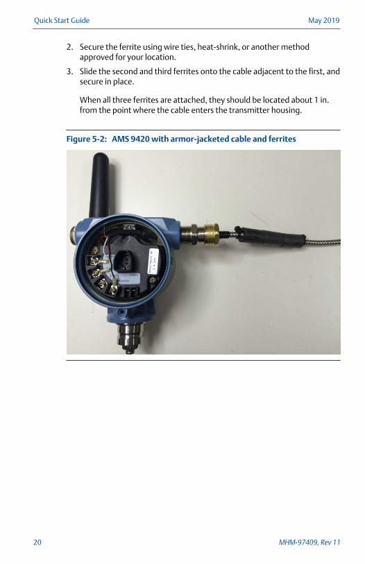
2. Secure the ferrite using wire ties, heat-shrink, or another methodapproved for your location.
3. Slide the second and third ferrites onto the cable adjacent to the first, andsecure in place.
When all three ferrites are attached, they should be located about 1 in.from the point where the cable enters the transmitter housing.
AMS 9420 with armor-jacketed cable and ferritesFigure 5-2:
Quick Start Guide May 2019
20 MHM-97409, Rev 11

6 Shipping considerations for wireless products(Lithium Batteries)
You may need to ship the device to an Emerson Product Service Center forreturn or maintenance. Before shipping, contact Emerson Product Support toobtain a Return Materials Authorization (RMA) number and receive additionalinstructions.
• The unit was shipped to you without the power module installed. Pleaseremove the power module prior to shipping the unit.
• Each blue power module contains two "D" size primary lithium-thionylchloride battery cells; each black power module contains two "C" sizeprimary lithium-thionyl chloride battery cells. Primary lithium batteriesare regulated in transportation by the U.S. Department ofTransportation, and are also covered by IATA (International Air TransportAssociation), ICAO (International Civil Aviation Organization), and ADR(European Ground Transportation of Dangerous Goods).
• It is the responsibility of the shipper to ensure compliance with these orany other local requirements. Please consult current regulations andrequirements before shipping.
May 2019 Quick Start Guide
MHM-97409, Rev 11 21
7 Troubleshooting
Are the Network ID and Join Key set correctly?
Verify the Network ID and Join Key in the device match those found on theEmerson Wireless Gateway:
1. From the Emerson Wireless Gateway, click System Settings > Network >Network Settings.
2. Verify Show join key has a check mark.
NoteThe most common cause of incorrect operation is that the Network ID or JoinKey are not set correctly in the device.
Have you disconnected your HART modem or Field Communicator aftercompleting configuration?
Disconnect your HART modem or Field Communicator immediately aftercompleting the configuration so the device will join the wireless network.
Does the AMS 9420's configuration match the connected sensors?
Ensure your configured parameters reflect the sensors installed on thedevice.
Quick Start Guide May 2019
22 MHM-97409, Rev 11

8 Product certifications
The AMS 9420 has a number of certifications and approvals including CE,FCC, RED, CSA, and ATEX. For a complete list of product certifications, see http://www.emerson.com/en-us/catalog/ams-a9420.
8.1 RoHS 2 (2011/65/EU)
The AMS 9420 was designed for incorporation into large, fixed industrialinstallations. Examples include - but are not limited to - cooling towers andother cooling systems, pumping systems, compressor systems, and systemsutilizing agitators or centrifuges. As such, the AMS 9420 is covered under theexclusion provided for Large Scale Fixed Installations and is therefore out ofscope for the current EU RoHS Directive 2011/65/EU.
Please contact Emerson’s Reliability Solutions office at +1-865-672-1062with any questions or concerns.
May 2019 Quick Start Guide
MHM-97409, Rev 11 23

Quick Start GuideMHM-97409, rev. 11
May 2019
Emerson835 Innovation DriveKnoxville, TN 37932 USAT +1 865-675-2400F +1 865-218-1401www.Emerson.com
©2019, Emerson.The contents of this publication are presented forinformational purposes only, and while every efforthas been made to ensure their accuracy, they arenot to be construed as warranties or guarantees,express or implied, regarding the products orservices described herein or their use orapplicability. All sales are governed by our termsand conditions, which are available on request. Wereserve the right to modify or improve the designsor specifications of our products at any timewithout notice.All rights reserved. The Emerson logo is atrademark and service mark of Emerson Electric Co.All other marks are property of their respectiveowners.