ams-9050 contents detection system - johnson controls
TRANSCRIPT

AMS-9050 DETECTION SYSTEM 8200-0537-01, REV. F PLANNING GUIDE 1 of 18
AMS-9050 Detection System Planning guide
Contents About this guide ..................................................... 1 About the product................................................... 2 General warnings and cautions ............................. 2 ZE9050 Controller .................................................. 3 Ultra Exit antennas................................................. 4 AMS-1080 Ultra•Lane Antennas ............................ 8 AMS-1081 Ultra Lane Antennas .......................... 10
AMS-1081 configurations ............................... 11 Dimensions and cable routing ........................ 13
Auxiliary Receiver Antennas ................................ 14 Satellite antennas ........................................... 14 Ranger Antennas ............................................ 15 Amorphous Core Receivers ............................ 16
Specifications ....................................................... 17 Declarations ......................................................... 18
About this guide This guide explains how to plan for the installation of the AMS-9050 detection system. Other guides may be required for planning. These guides are as follows: • AMS-9050 Controller Installation and Service
Guide, 8200-0537-02. • Ultra•Exit Transceiver Antennas (AMS-1090/
AMS-1100 Series) Installation Guide, 8200-0537-16.
• Ultra•Lane™ Antenna Installation Guide, 8200-0418-04.
• Amorphous Core Receiver Installation Guide 8200-0867-01.
• Accessibility for the Disabled Guide, 8000-2685-01.
• Ultra•Exit Transceiver Antenna 25m (82ft) Cable Kit Installation Guide, 8200-0537-34.
• 3-Meter Cable Extension Assembly for ZSAISLE Installation Guide, 8200-0623-01.
• AMS-1081 Ultra Lane Antennas Installation Guide 8200-1014-11
Regulatory restriction: For indoor use only.
ZSAISLE
ZE9050
ZS1100/ ZS1122
ZS1101 ZS1102
ZS1090 ZS1092
ZS1091
ZS1121 ZS1123 ZS1121-CN
ZS1131 ZS1130 ZS1132 ZS1133-PIEZO
© 2016 Sensormatic Electronics, LLC

AMS-9050 DETECTION SYSTEM 8200-0537-01, REV. F PLANNING GUIDE 2 of 18
About the product The AMS-9050 detection system consists of a ZE9050 controller (Page 2) and the following antennas:
Minimum and maximum exit coverage Antenna type
Exit coverage Page Min. Max.
Ultra•Exit (2m) 0.9m (3ft) 7.6m
(24ft 11in) 6
Ultra•Exit (2.4m) 1m (3ft 3in) 8.8m
(28ft 10in) 7
AMS-1080 0.8m (2ft 7.5in)
1.8m (5ft 11in)* 8
AMS-1081 0.8m (2ft 7.5in)
1.8m (5ft 11in)* 10
* 7m (23ft) when AMS-1080 antennas are used as an exit system.
Noise canceling antennas (optional) Noise canceling antennas are used to reduce or eliminate noise interference. These antennas only receive signals; they do not transmit and they do not contain an alarm. Auxiliary receiver antennas can be used for this purpose. See page 14.
ADA statement Pedestal location may be affected by accessibility guidelines for the disabled. For guidelines in the USA, see Accessibility for the Disabled Installation Guide 8000-2685-01.
General warnings and cautions
WARNING: Do not install this product where highly combustible or explosive products are stored or used.
Installer/contractor The installer/contractor shall obtain copies of all related plans, specifications, shop drawings and addenda to schedule and coordinate related work.
Electrical considerations All electrical work must comply with the latest national electrical and fire codes, and all applicable local codes and ordinances.
• The ac source must be a 3-wire, 24-hour, 50 or 60Hz, unswitched outlet with less than 0.5Vac between neutral and ground.
• Do not share the AC source with neon signs, motors, computers, cash registers, terminals, or data communications equipment.
• Do not use orange-colored outlets dedicated to computer equipment.
• If a power cord is used, ensure it is appropriate for the country of use. Power cords are approximately 2m (6.6ft) long.
CAUTION: When using a power cord, install a socket-outlet near the controller in an accessible location. CAUTION: A 10A, 2-pole, ganged disconnect device, which also provides short circuit and overload protection, and has a minimum 3mm open circuit clearance, in accordance with the National Electric Code and applicable local codes must be installed by a licensed electrician at a location readily accessible to the equipment.
Electrical interference The detection system operation can affect or be affected by other electronic equipment. • The system generates magnetic field bursts that
can interfere with automatic door openers, magnetic readers, and access control devices. These fields can also distort nearby CRT screens; LCD/LED displays are not affected.
Electronic equipment such as microwave proximity sensors used for automatic doors, computer monitors, variable frequency drives (VFDs), solid-state ballasts, and ATM machines can affect the detection system. Keep antennas at least 2.4m (8ft) away from these devices whenever possible. Note: VFD devices, used to conserve energy in HVAC equipment, emit harmonics along electrical lines. An EMI/RFI line filter may need to be installed between the VFD device and the electrical line to eliminate the interference. For more information about VFDs or line filters, contact Sensormatic Technical Support at 800-543-9740.
Implanted medical devices This anti-theft system complies with all applicable safety standards. However, people with implanted electronic medical devices may ask if the store has an anti-theft system, and its location. Although
AMS-9050 DETECTION SYSTEM 8200-0537-01, REV. F PLANNING GUIDE 3 of 18
most anti-theft systems are easily seen, some can be concealed. To help these people, do the following:
Consider health and safety Place the anti-theft system antennas so customers: • Do not linger near or lean on them while making
their purchase. • Are only near the front of them while exiting the
checkout area.
For exit systems, place anti-theft system antennas: • Close to exit/entrance doors, encouraging the
customer to pass through them. DO NOT use antennas intended for exits in an aisle configuration.
• Away from fixtures, equipment, amusements, and other signage that can attract customers to them.
Apply ‘Anti-Theft’ signage • ‘Anti-Theft’ labels are placed on each antenna,
including those hidden behind door frames and other structures. DO NOT cover these labels with other signage.
• In non-English speaking countries, apply ‘Anti-Theft’ labels in the local language to the antennas. For hidden antennas, apply an ‘Anti-Theft’ label in the local language each side of the door frame facing the doorway about 1.2m (4ft) above the floor. Order local language labels (2412-0170-XX) from your distribution center.
• To improve customer awareness of the anti-theft system, encourage the store to display signs that state it has an anti-theft system. Order awareness materials through your sales representative.
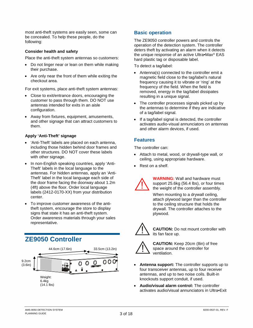
ZE9050 Controller
Basic operation The ZE9050 controller powers and controls the operation of the detection system. The controller deters theft by activating an alarm when it detects the unique response of an active Ultra•Max® EAS hard plastic tag or disposable label. To detect a tag/label: • Antenna(s) connected to the controller emit a
magnetic field close to the tag/label’s natural frequency causing it to vibrate or ‘ring’ at the frequency of the field. When the field is removed, energy in the tag/label dissipates resulting in a unique signal.
• The controller processes signals picked up by the antennas to determine if they are indicative of a tag/label signal.
• If a tag/label signal is detected, the controller activates audio-visual annunciators on antennas and other alarm devices, if used.
Features The controller can: • Attach to metal, wood, or drywall-type wall, or
ceiling, using appropriate hardware. • Rest on a shelf.
WARNING: Wall and hardware must support 25.6kg (56.4 lbs), or four times the weight of the controller assembly. When mounting to a drywall ceiling, attach plywood larger than the controller to the ceiling structure that holds the drywall. The controller attaches to the plywood.
CAUTION: Do not mount controller with its fan face up.
CAUTION: Keep 20cm (8in) of free space around the controller for ventilation.
• Antenna support: The controller supports up to
four transceiver antennas, up to four receiver antennas, and up to two noise coils. Built-in knockouts support conduit, if used.
• Audio/visual alarm control: The controller activates audio/visual annunciators in Ultra•Exit
33.5cm (13.2in)
9.2cm (3.6in)
Weight: 6.4kg (14.1 lbs)
44.6cm (17.6in)

AMS-9050 DETECTION SYSTEM 8200-0537-01, REV. F PLANNING GUIDE 4 of 18
(except AMS-1100 and 1122) and Ultra•Lane pedestal antennas. – Alarm parameters can be independently
selected and adjusted for zone identification. – Supports audio messages in optional AMC-
1060 remote alarm/message unit. • Auto synchronization: To avoid interference
from nearby EAS detectors, upon power up or system reset, the controller automatically adjusts its operation to the ac-timed functions of nearby EAS transmitters, if detected.
• Jammer event trigger: The controller can be set to alert store personnel to the presence of a 58kHz jamming device.
• Tag-too-close function: This function is used with pedestal antennas having built-in visual indicators to help prevent false alarms. With this function selected, the red lamp on top of the antenna blinks twice every four seconds for one minute when the system detects one or more tags or labels displayed too close to the antenna.
• Power connection: Ac power connects to the controller using a power cord. The controller supports 100-120Vac or 200-240Vac.
Options • AMC-1060 remote alarm/message unit: The
alarm indicates when a tag or label is detected. The alarm/message unit is externally powered by a transformer.
• External devices: The controller has two relay outputs to trigger external devices such as security cameras.
• Sensormatic alarm management or people counting device: This device enhances the system by offering data logging and people counting functions. The device is externally powered by a transformer.
• Satellite/Ranger receiver antennas: These wall-mounted antennas only receive; they do not transmit and they do not contain an alarm. Note: These antennas can also serve as noise canceling antennas. The controller can support up to two noise canceling antennas.
• 3m cable extension assembly: This item adds 3m (10ft) to the length of a transceiver antenna cable, allowing an Ultra•Lane pedestal to be installed up to 15.2m (50ft) from the controller.
• Ultra•Exit antenna 25m cable kit: This kit replaces the 12.2m (40ft) standard length transceiver and alarm/ com cables with 25m
(82ft) extended length cables for a 2.4m Ultra•Exit pedestal antenna. Note that the separation between two 2.4m pedestals can be no more than 2.0m (6ft 6in) when using the optional 25m (82ft) cables.
Ultra Exit antennas Features The Ultra•Exit pedestal antenna emits the detection field and receives the tag/label signal. Note: See appropriate installation guides for the controller and pedestal for connections, limitations, and important details. The pedestal features: • Transceiver operation, where each antenna
simultaneously transmits and receives signals. The antennas can also operate in Backfield Reduction mode or Alternating mode. Backfield Reduction mode is a configuration used for a two pedestal system in which one pedestal is configured as a transmitter only, and one pedestal is configured as a receiver only. It minimizes the detection field behind (on the outside) of the pedestal in a two pedestal system. Neither pedestal is a transceiver and as a result, cannot detect a tag on its own. This configuration may be selected if tags are in close proximity to the system. Pedestal separation will be compromised somewhat in this configuration. Alternating mode is a configuration in which one antenna operates as a transmitter and the other antenna operates as a receiver for one cycle and then they swap duties for the next cycle. This configuration may be selected if tags are in close proximity to the system. Pedestal separation will be compromised somewhat in this configuration.
• Satellite antennas may improve exit coverage (see ‘Auxiliary Receive Antennas’ on page 14).
• Floor mount. • Alarm lamp with audio alarm in the base of the
pedestal. • When an alarm pedestal is placed between two
others to create two aisles, the alarm lamp can be set to light only in the aisle where a label was detected.

AMS-9050 DETECTION SYSTEM 8200-0537-01, REV. F PLANNING GUIDE 5 of 18
• Transmitter/Alarms inhibit switch located in the alarm lamp board. It is accessed through the lens on the AMS-1101 and under the lens on all other Ultra•Exit antennas.
• ‘System on’ lamp that lights when the system is on for all antennas with alarm lamps.
• Integrated People Counting Kit (option for all Ultra•Exit antennas except the AMS-1100, 1101, and 1122).
• Base covers that cover the capacitor board. These covers come in several versions: stainless steel angled (standard) and stainless steel square, and molded plastic. The base cover, on all pedestals except the AMS-1100 and AMS-1122, accepts the optional alarm counter.
• 12.2m (40ft) cables from controller to pedestal. Optional 25m (82ft) cable kits available for 2.4m antennas. Note that the separation between two 2.4m pedestals can be no more than 2.0m
(6ft 6in) when using the optional 25m (82ft) cables.
Requirements • Do not place store fixtures, advertisements,
equipment, or amusements near antennas. These items can conceal antennas and encourage consumers to linger near them.
• A transmit field is emitted from both sides of the pedestal. To avoid false alarms, keep tagged displays at least 1.5m (5ft) from the pedestal, especially when using the tag-too-close function.
Pedestal location may be affected by accessibility guidelines for the disabled. For guidelines in the USA, see Accessibility for the Disabled Installation Guide, 8000-2685-01.
Feature
AM
S-10
90
AM
S-10
91
AM
S-10
92
AM
S-11
00
AM
S-11
01
AM
S-11
02
AM
S-11
21
AM
S-11
21-C
N*
AM
S-11
22
AM
S-11
23
AM
S-11
30
AM
S-11
31
AM
S-11
32
AM
S-11
33
Max Coverage Distance (m) 2.0 2.0 2.0 2.0 2.0 2.0 2.4 2.4 2.4 2.4 2.4 2.4 2.4 2.4 Alarm Lamp ● ● ● ○ ● ● ● ● ○ ● ● ● ● ● Alarm Buzzer ● ● ● ○ ● ● ● ● ○ ● ● ● ● ● System On Lamp ● ● ● ○ ● ● ● ● ○ ● ● ● ● ● Tx/Alarms Inhibit Switch ● ● ● ○ ● ● ● ● ○ ● ● ● ● ● Integrated People Counting
Option ● ● ● ○ ○ ● ● ● ○ ● ● ● ● ●
Alarm Counter Option ● ● ● ○ ● ● ● ● ○ ● ● ● ● ● Custom Panel Kit Option ● ○ ● ○ ○ ○ ○ ○ ○ ○ ● ○ ● ● Acrylic Panel Upgrade Option ● ○ ● ○ ○ ○ ○ ○ ○ ○ ● ○ ● ● Edge Bumper Option ● ● ● ○ ○ ○ ○ ○ ○ ○ ● ● ● ● 25m Cable Kit Option ○ ○ ○ ○ ○ ○ ● ● ○ ● ● ○ ● ○ Speaker Upgrade Kit ○ ○ ○ ○ ○ ○ ○ ○ ○ ○ ● ○ ○ ○ ● – Feature is either standard or available as an option ○ – Feature is not available on this model * – Available in China only Model numbers in gray text are obsolete and not available at the date of printing.
AMS-9050 DETECTION SYSTEM 8200-0537-01, REV. F PLANNING GUIDE 6 of 18
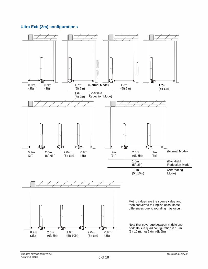
Ultra Exit (2m) configurations
0.9m (3ft)
0.9m (3ft)
.9m (3ft)
.9m (3ft)
2.0m (6ft 6in)
0.9m (3ft)
2.0m (6ft 6in)
0.9m (3ft)
2.0m (6ft 6in)
0.9m (3ft)
2.0m (6ft 6in)
0.9m (3ft)
2.0m (6ft 6in)
1.8m (5ft 10in)
1.7m (5ft 6in)
1.7m (5ft 6in)
1.6m (5ft 3in)
(Backfield Reduction Mode)
1.8m (5ft 10in)
(Alternating Mode)
(Normal Mode)
Metric values are the source value and then converted to English units; some differences due to rounding may occur.
(Backfield Reduction Mode)
(Normal Mode)
1.6m (5ft 3in)
1.7m (5ft 6in)
Note that coverage between middle two pedestals in quad configuration is 1.8m (5ft 10in), not 2.0m (6ft 6in).

AMS-9050 DETECTION SYSTEM 8200-0537-01, REV. F PLANNING GUIDE 7 of 18
Ultra Exit (2.4m) configurations
1.0m (3ft 3in)
1.0m (3ft 3in)
1.0m (3ft 3in)
1.0m (3ft 3in)
2.4m (7ft 10in)
(Normal Mode)
1.8m (5ft 10in)
(Backfield Reduction Mode)
2.0m (6ft 6in)
(Alternating Mode)
1.0m (3ft 3in)
2.4m (7ft 10in)
1.0m (3ft 3in)
2.4m (7ft 10in)
1.0m (3ft 3in)
2.4m (7ft 10in)
1.0m (3ft 3in)
2.4m (7ft 10in)
2.0m (6ft 6in)
Note that coverage between the middle two pedestals in quad configuration is 2.0m (6ft 6in), not 2.4m (7ft 10in).
2.0m (6ft 6in)
2.0m (6ft 6in)
Metric values are the source value and then converted to English units; some differences due to rounding may occur.
(Normal Mode)
(Backfield Reduction Mode)
1.8m (5ft 10in)
2.0m (6ft 6in)
Note that the separation between two 2.4m pedestals can be no more than 2.0m (6ft 6in) when using the optional 25m (82ft) cables.

AMS-9050 DETECTION SYSTEM 8200-0537-01, REV. F PLANNING GUIDE 8 of 18
AMS-1080 Ultra•Lane Antennas
Features The AMS-1080 model is one of the Ultra Lane Antenna product suite. The pedestal emits a detection field and receives the tag/label signal. Note: See appropriate installation guides for the controller and pedestal for connections, limitations, and important details. The pedestal features: • Transceiver or transmit/receive only operation. • Wall or counter mounting, or to a railing post
between adjacent aisles. • Audio/visual alarm at the top of the pedestal
that detected the label. When the pedestal is between two adjacent aisles, one side of the alarm lamp can be set to light independent of the other in the aisle where a label was detected.
• ‘Transmitter on’ lamp under the alarm lamp lens cover flashes when the transmitter is on.
• Two hardwired, burial-rated cables that connect to the controller. Cable length is 7m (23ft).
• The AMS-1080 antenna works with the AMS-9050 and AMS-1080 controllers.
Requirements • Pedestals furthest from the controller require a
trench to route cables to the controller. • Keep the surface of the pedestal at least 5cm
(2in) from the surface of a metal-sided counter.
AMS-1080 configurations AMS-1080 pedestals can support the following aisle/exit configurations:
Aisle configurations
Up to four aisles. • One pedestal is set up as a transceiver in each
aisle. • Pedestals can be set to alarm independently. • Pedestals may require a trench to route their
cables to the controller. Note: This configuration may need 3m (10ft) cable extension assembly kit ZPUM-EXTCBL for cables to reach from the fourth antenna to the controller.
Up to four aisles with backfield reduction. • Pedestals at one side of the aisle are set up as
transmitters. Ranger antennas at the other side of the aisle receive only.
• Pedestals can be set to alarm independently. • Pedestals may require a trench to route their
cables to the controller. • Whenever possible, attach Ranger antennas to
the end of the counter to avoid damage. Note: This configuration may need 3m (10ft) cable extension assembly kit ZPUM-EXTCBL for cables to reach from the fourth pedestal to the controller.
ZSAISLE

AMS-9050 DETECTION SYSTEM 8200-0537-01, REV. F PLANNING GUIDE 9 of 18
Up to two aisles with improved detection. • Pedestals at one side of the aisle are set up as
transceivers. Ranger antennas at the other side of the aisle receive only.
• Pedestals in each aisle can be set to alarm independently.
• Pedestals may require a trench to route their cables to the controller.
• Whenever possible, attach Ranger antennas to the end of the counter to avoid damage.
Up to two pairs of adjacent aisles. • For each set of adjacent aisles, a pedestal
antenna on a railing post between the aisles is set up as a transmitter and a pair of Ranger receive antennas are set up opposite each side of the pedestal.
• The alarm lamp in the pedestal automatically signals the aisle where detection occurs.
• Pedestals may require a trench to route their cables to the controller.
• Whenever possible, attach Ranger antennas to the end of the counter to avoid damage.
Exit configurations Two pedestal antennas at a doorway. • Pedestals can be set either in alternating
transmit-receive or dual transceiver configurations.
• Alarms in both antennas activate simultaneously.
Three pedestal antennas at a doorway. • Each pedestal is set up as a transceiver. • The alarm lamp in the pedestal automatically
signals the aisle where detection occurred. • Pedestals require a trench to route their cables
to the controller.
Four pedestal antennas at a doorway. • Each pedestal is set up as a transceiver. • The alarm lamp in the pedestal automatically
signals the aisle where detection occurs. • Pedestals require a trench to route their cables
to the controller. Note: This configuration may need 3m (10ft) cable extension assembly kit ZPUM-EXTCBL for cables to reach from the fourth antenna to the controller.

AMS-9050 DETECTION SYSTEM 8200-0537-01, REV. F PLANNING GUIDE 10 of 18
AMS-1081 Ultra Lane Antennas
ZS1081-DG, ZS-1081-DG10M, ZS1081-LG
Features
• The AMS-1081 model is one of the UltraLane Antenna product suite. The pedestal emits the detection field and receives the tag/label signal. The pedestal emits a detection field and receives the tag/label signal.
• AMS-1081 antennas are sealed at the factory. Internal components are not accessible.
• AMS-1081 antennas contain a self-tuning capacitor board that optimizes antenna performance to the conditions at the installation site. No manual tuning is necessary.
• Each AMS-1081 antenna is assigned a unique address for communications with the controller. The address select switch on the alarm board is accessed by removing the alarm lens at the top of the antenna.
• Alarm LEDs are mounted on each side of the AMS-1081 antenna's alarm board to support individual zone detection.
• AMS-1081 antennas mount to the side of a wall or counter, on railing posts, or on mullions using hardware supplied with the install kits.
• Two hardwired burial-rated cables connect each AMS-1081 antenna to the controller. Cable length for ZS1081-DG or ZS1081-LG antenna is 7m (23ft). Cable length for ZS1081-DG10M antenna is 10m (33ft).
• The AMS-1081 differs from the AMS-1080 as follows:
a. The AMS-1081 is approved to operate with a AMS-9060 controller
b. The AMS-1081 has an address switch
Note: The AMS-1080 is not compatible with the AMS-1081 pedestal.
• Controllers that work with the AMS-1081:
o AMS-9050
o AMS-9060.
CAUTION: Do not cut communication cables shorter than 7m (23ft). Shorter cables reduce operating performance.
Requirements
• Pedestals furthest from the controller require a trench to route cables to the controller.
• Keep the surface of the pedestal at least 5cm (2in) from the surface of a metal-sided counter.

AMS-9050 DETECTION SYSTEM 8200-0537-01, REV. F PLANNING GUIDE 11 of 18
AMS-1081 configurations AMS-9050 system can be configured as either aisle systems or exit systems.
Aisle systems The detector consists of an AMS-9050 and one of the following antenna combinations:
• Aisle transceivers: Up to four aisles are supported. For this configuration, an AMS-1081 antenna is set up as a transceiver in each aisle. The AMS-1081 antennas in each aisle can be set to alarm independently. Antennas require a trench to route their cables to the controller. A 3-Meter Cable Extension Kit, ZPUM-EXTCBL, may be required to extend antenna cables for one antenna.
• Aisle backfield: Up to four aisles are supported. For backfield reduction, the AMS-1081 antenna is set up as a transmitter-only in each aisle, and a pair of Ranger receiver antennas are set up opposite the antenna. The AMS-1081 antennas in each aisle can be set to alarm independently. Antennas require a trench to route their cables to the controller. A 3-Meter Cable Extension Kit, ZPUM-EXTCBL, may be required to extend antenna cables for one antenna.
• Aisle Transceiver-Ferrites: Up to two aisles are supported. For improved detection, an AMS-1081 antenna is set up as a transceiver in each aisle and a pair of Ranger receive antennas are set up opposite the antenna. The AMS-1081 antennas in each aisle can be set to alarm independently. Antennas require a trench to route their cables to the controller.
TXA/RXA TXB/RXB TXC/RXC TXD/RXD
1 2 3 4
TXA TXB TXC TXD RXA RXB RXC RXD
1 2 3 4
TXA/RXA TXB/RXB RXC RXD
1 2

AMS-9050 DETECTION SYSTEM 8200-0537-01, REV. F PLANNING GUIDE 12 of 18
• Dual Aisle Zone Detect: Up to two individual pairs of adjacent aisles are supported. For each adjacent aisle, an AMS-1081 antenna is set up as a transmitter on a railing post between the two aisles. A pair of Ranger receive antennas are setup on each side of the AMS-1081 antenna. The alarm LEDs in the AMS-1081 antenna automatically signals the aisle where detection occurred. Antennas require a trench to route their cables to the controller.
Exit systems The detector consists of an AMS-9050 controller or an AMS-9060 controller and one of the following antenna combinations: • Dual Exit, Backfield or Alternating: Up to two
doorways are supported with two AMS-1081 antennas in a doorway and each antenna is set up as a transceiver. Each pair of antennas can be set to transmit simultaneously (dual exit) or in an alternating transmit-receive mode (alternating). Antennas require a trench to route their cables to the controller.
Dual Exit or Backfield
Alternating (AMS-9050 only)
• Split Exit: A single doorway is supported with three AMS-1081 antennas and each antenna is set up as a transceiver. The alarm LEDs in the AMS-1081 antenna automatically signal the aisle where detection occurred. Antennas require a trench to route their cables to the controller.
AMS-9060
AMS-9050
• Quad Exit: A single doorway is supported with four AMS-1081 antennas and each antenna is set up as a transceiver. The alarm LEDs in the AMS-1081 antenna automatically signal the aisle where detection occurred. Antennas require a trench to route their cables to the controller.
TXA TXB RXA RXC RXB RXD
1A 1B 2A 2B
TXA/RXA TXB/RXB TXC/RXC TXD/RXD
TXA/RXA TXC/RXC TXB/RXB TXD/RXD
TXA/RXA TXB/RXB TXC/RXC
TXA/RXA TXC/RXC TXB/RXB TXD/RXD
TXA/RXA TXC/RXC TXB/RXB

AMS-9050 DETECTION SYSTEM 8200-0537-01, REV. F PLANNING GUIDE 13 of 18
Dimensions and cable routing ZEAISLE pedestal installed against counter with Ranger antennas
ZEAISLE pedestal installed between aisles on railing post with Ranger antennas
CAUTION: Keep the surface of the AMS-1080 antenna at least 5cm (2in) from the surface of a metal-sided counter.
Cables in trench
Two 7m (23ft) AMS-1080 Antenna Cables (burial rated)
12.2m (40ft) Ranger Cable (burial rated)
17.8cm (7in)
2.5cm (1in)
10.2cm (4in)
Ranger Antenna
(side view)
2.5cm (1in)
10.2cm (4in)
36.4cm (14.3in)
121.3cm (47.8in)
Cables in trench
12.2m (40ft) Ranger Cable (burial rated)
Two 7m (23ft) AMS-1080 Antenna Cables (burial rated)
10.2cm (4in)
Ranger Antenna Depth: 8cm (3in) Width: 3.8cm (1.5in) Height: 24cm (9.5in) Weight: 0.5kg (1 lb)
Antenna 5.2kg (11.5lbs)
(side view)
17.8cm (7in)

AMS-9050 DETECTION SYSTEM 8200-0537-01, REV. F PLANNING GUIDE 14 of 18
Auxiliary Receiver Antennas Auxiliary receiver antennas: • Can only receive the tag/label signal • Are used to expand the exit coverage of the
detection system or for noise cancellation • Come in three types: Satellite, Ranger, and
Amorphous Core Receiver.
Satellite antennas ZKRXMULLMT Satellite antennas, also called mullion-mount antennas, can increase exit coverage by 0.6–0.76m (2–2.5ft). Exact coverage depends on the type of detection system antenna used and the surrounding environment. • Satellite antennas mount to a wall or counter
opposite one or both sides of a vertical antenna. • The controller supports up to eight Satellite
antennas. • Maximum cable length between a Satellite
antenna and controller is 12m (40ft). • Keep Satellite antennas 0.6m (2ft) or more from
CCTV cameras and domes; 1m (3ft) or more from active transmitters.
See installation guide for Satellite antennas for additional information.
72.5cm (28.5in)
8.7cm (3.4in)
14.3cm (5.6in)
Weight: 4.5kg (10 lbs)
AMS-9050 DETECTION SYSTEM 8200-0537-01, REV. F PLANNING GUIDE 15 of 18
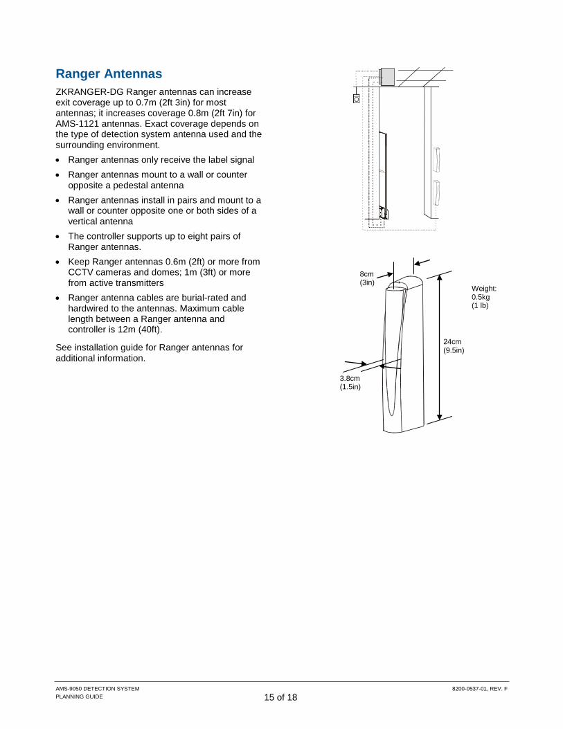
Ranger Antennas ZKRANGER-DG Ranger antennas can increase exit coverage up to 0.7m (2ft 3in) for most antennas; it increases coverage 0.8m (2ft 7in) for AMS-1121 antennas. Exact coverage depends on the type of detection system antenna used and the surrounding environment. • Ranger antennas only receive the label signal • Ranger antennas mount to a wall or counter
opposite a pedestal antenna • Ranger antennas install in pairs and mount to a
wall or counter opposite one or both sides of a vertical antenna
• The controller supports up to eight pairs of Ranger antennas.
• Keep Ranger antennas 0.6m (2ft) or more from CCTV cameras and domes; 1m (3ft) or more from active transmitters
• Ranger antenna cables are burial-rated and hardwired to the antennas. Maximum cable length between a Ranger antenna and controller is 12m (40ft).
See installation guide for Ranger antennas for additional information.
24cm (9.5in)
8cm (3in)
3.8cm (1.5in)
Weight: 0.5kg (1 lb)

AMS-9050 DETECTION SYSTEM 8200-0537-01, REV. F PLANNING GUIDE 16 of 18
Amorphous Core Receivers Amorphous core receivers are available in two kits: ZSLOOP-AMRX-1 (a single receiver kit with one pair of antennas) and ZSLOOP-AMRX (a dual receiver kit with two pairs of antennas). Installing these receivers requires the single raceway kit (ZP3004-RW-1) or dual raceway kit (ZP3004-RW), respectively. Amorphous core receivers can be used to increase the Ultra•Exit antennas exit coverage. The increase in coverage is based on where the receiver is installed in relation to the pedestal. For example, if an amorphous core receiver is installed to a system that uses a single Ultra•Exit antenna in the center of an exit, the increase in coverage will be 0.8m to each side of the pedestal. If an amorphous core receiver is installed to a system that uses a single Ultra•Exit antenna that is placed next to a wall, the increase in coverage will be 0.8m to one side of the pedestal. Amorphous core receivers can increase exit coverage for Ultra•Exit antennas by up to 0.8m (2ft 7in) for each amorphous antenna, and 1.0m (3ft 3in) for each amorphous antenna. Exact coverage depends on the type of detection system antenna used and the surrounding environment. • Amorphous core receivers only receive the label
signal. • Amorphous core receivers are installed in pairs
in a raceway. • Amorphous core receivers mount to a wall
opposite one or both sides of a vertical antenna. • The controller supports up to four pairs of
amorphous core receivers. • Keep amorphous core receivers 0.6m (2ft) or
more from CCTV cameras and domes; 1m (3ft) or more from active transmitters.
• Amorphous core receiver cables are burial-rated, plenum-rated, and hardwired to the antennas. Maximum cable length between amorphous core receivers and the controller is 12.2m (40ft).
See the installation guide for amorphous core receivers for additional information.
Amorphous Core Receivers

AMS-9050 DETECTION SYSTEM 8200-0537-01, REV. F PLANNING GUIDE 17 of 18
Specifications Electrical Power supply: Primary input ............................................ 100-120Vac or
200-240Vac @ 50–60Hz Primary power fuse ......................... 2.5A, 250V, slo-blow,
hi-breaking Current draw (120V) ......................................... <1.5Arms Current draw (240V) ............................................ <1Arms Input power (120V) ............................................... <130W Input power (240V) ............................................... <123W
TRANSMITTER Operating frequency ............................... 58kHz (±200Hz) Transmit burst duration ........................................... 1.6ms Max Transmit current (2.4m pedestals) ............ 20A peak Max Transmit current (2m pedestals) ............... 16A peak
Burst Repetition Rate: Based on 50Hz ac ................................ 75Hz or 37.5Hz Based on 60Hz ac ................................... 90Hz or 45Hz
RECEIVER Center frequency ................................................... 58kHz
ALARM Audio Alarm Level............................................... 82dB(A)
Environmental Ambient temperature ........... 0°C to 50°C (32°F to 122°F) Relative humidity ..................... 0 to 90% non-condensing
Enclosure .................................................................. IPX0 Evaluated for altitudes < 2000m (6500ft)
Mechanical ZE9050 Controller Height .......................................................... 9.2cm (3.6in) Width ....................................................... 33.5cm (13.2in) Length ...................................................... 44.6cm (17.6in) Weight ..................................................... 6.4kg (14.1 lbs)
AMS-1100/1101/1102/1121/1122/1123 Acrylic Pedestal Antennas Height .......................................................... 155cm (61in) Width ....................................................... 49.2cm (19.4in) Thickness (with base covers) .................... 12.5cm (4.9in) Weight (with base covers) ..................... 25.7kg (56.7 lbs)
AMS-1090/1092 and AMS-1130/1132/1133 Pedestal Antennas Height .......................................................... 155cm (61in) Width .......................................................... 50.9cm (20in) Thickness (with base covers) .................... 12.5cm (4.9in) Weight (with base covers) ....................... 9.7kg (21.3 lbs)
AMS-1091 and AMS-1131 Pedestal Antennas Height .......................................................... 155cm (61in) Width .......................................................... 50.9cm (20in) Thickness (with base covers) .................... 12.5cm (4.9in) Weight (with base covers) ..................... 16.3kg (35.9 lbs)
AMS-1080/1081 Pedestal Antenna Height .................................................... 121.3cm (47.8in) Width ....................................................... 36.4cm (14.3in) Thickness .................................................... 3.6cm (1.4in) Weight .................................................... 5.2kg (11.5 lbs.)
Satellite (ZKRXMULLMT) Receive Auxiliary Antenna Length ..................................................... 72.5cm (28.5in) Diameter ..................................................... 8.7cm (3.4in) Depth (including bracket) .......................... 14.3cm (5.6in) Weight ........................................................ 4.5kg (10 lbs)
Ranger (ZKRANGER-DG) Receive Antenna Height ........................................................... 24cm (9.5in) Width ........................................................... 3.8cm (1.5in) Depth ................................................................ 8cm (3in) Weight ............................................................ 0.5kg (1 lb)

AMS-9050 DETECTION SYSTEM 8200-0537-01, REV. F PLANNING GUIDE 18 of 18
Declarations Regulatory ID List:
Product name Product code Regulatory ID AMS-9050 Controller ZE9050 AMS-9050
Digital Remote Alarm ZP1060-W ZP1060-G
AMC-1060
Ultra•Exit Transceiver Antennas
ZS1090 ZS1091 ZS1092 ZS1100 ZS1101 ZS1102 ZS1121 ZS1121-CN ZS1122 ZS1123 ZS1130 ZS1131 ZS1132 ZS1133-PIEZO
AMS-1090 AMS-1091 AMS-1092 AMS-1100 AMS-1101 AMS-1102 AMS-1121 AMS-1121 AMS-1122 AMS-1123 AMS-1130 AMS-1131 AMS-1132 AMS-1133
AMS-1080 Ultra Lane ZSAISLE AMS-1080 ANT
AMS-1081 Ultra Lane ZS1081-DG, ZS1081-DG10M ZS1081-LG
AMS-1081
Ranger Antennas ZKRANGER-DG ZKRANGER-3
UM UPFAF
Satellite Antenna ZKRXMULLMT UM POST-M
Regulatory compliance AMS-9050 Controller: EMC ....................................................... 47 CFR, Part 15 EN 61000-3-2 EN 61000-3-3 ETSI EN 300 330-2 ETSI EN 301 489-3 ETSI EN 301 489-1 RSS-210 Safety (second edition) ................................. UL 60950-1 CSA C22.2.60950-1 EN 60950-1
FCC ID: BVCAMS9050 FCC COMPLIANCE: This equipment complies with Part 15 of the FCC rules for intentional radiators and Class A digital devices when installed and used in accordance with the instruction manual. Following these rules provides reasonable protection against harmful interference from equipment operated in a commercial area. This equipment should not be installed in a residential area as it can radiate radio frequency energy that could interfere with radio communications, a situation the user would have to fix at their own expense. INDUSTRY CANADA STATEMENT: This Class A digital apparatus complies with Canadian ICES-003. Cet appareil numérique de la classe A est conforme á la norme NMB-003 du Canada. IC: 3506A-AMS9050 EQUIPMENT MODIFICATION CAUTION: Equipment changes or modifications not expressly approved by Sensormatic Electronics, LLC, the party responsible for FCC compliance, could void the user's authority to operate the equipment and could create a hazardous condition.
Other declarations WARRANTY DISCLAIMER: Sensormatic Electronics, LLC makes no representation or warranty with respect to the contents hereof and specifically disclaims any implied warranties of merchantability or fitness for any particular purpose. Further, Sensormatic Electronics, LLC reserves the right to revise this publication and make changes from time to time in the content hereof without obligation of Sensormatic Electronics, LLC to notify any person of such revision or changes. LIMITED RIGHTS NOTICE: For units of the Department of Defense, all documentation and manuals were developed at private expense and no part of it was developed using Government Funds. The restrictions governing the use and disclosure of technical data marked with this legend are set forth in the definition of “limited rights” in paragraph (a) (15) of the clause of DFARS 252.227.7013. Unpublished - rights reserved under the Copyright Laws of the United States. TRADEMARK NOTICE: Sensormatic is a registered trademark of Sensormatic Electronics, LLC. Other product names mentioned herein may be trademarks or registered trademarks of Sensormatic or other companies. No part of this guide may be reproduced in any form without written permission from Sensormatic Electronics, LLC.