amplitude modulation dsb-scihayee/teaching/ee5765/ece5765_chapter_4_5.pdfamplitude modulation...
TRANSCRIPT
Department of Electrical and Computer Engineering
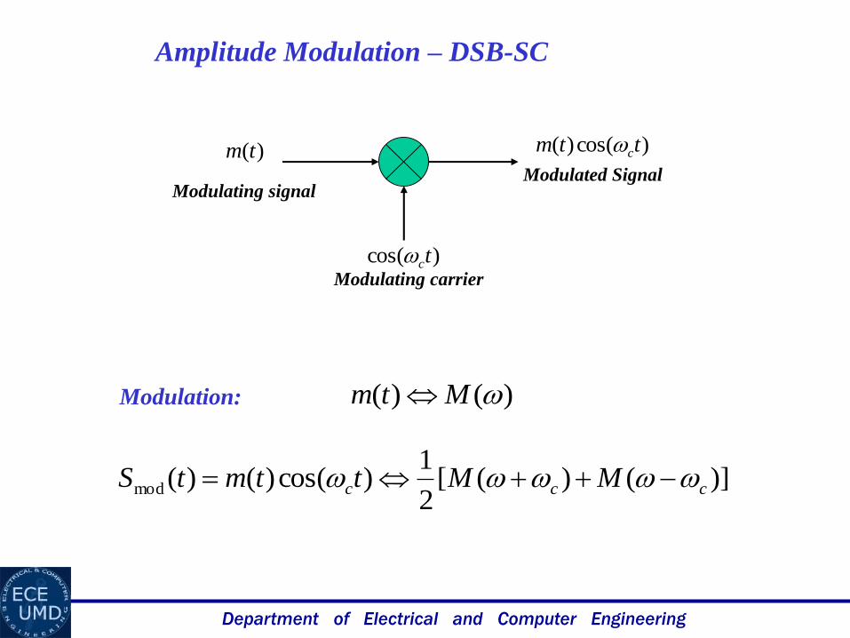
Amplitude Modulation – DSB-SC
Modulation: )()( Mtm
)]()([2
1)cos()()(mod ccc MMttmtS
)(tm
)cos( tc
)cos()( ttm c
Modulating signalModulated Signal
Modulating carrier
Department of Electrical and Computer Engineering
)(M
BB
c
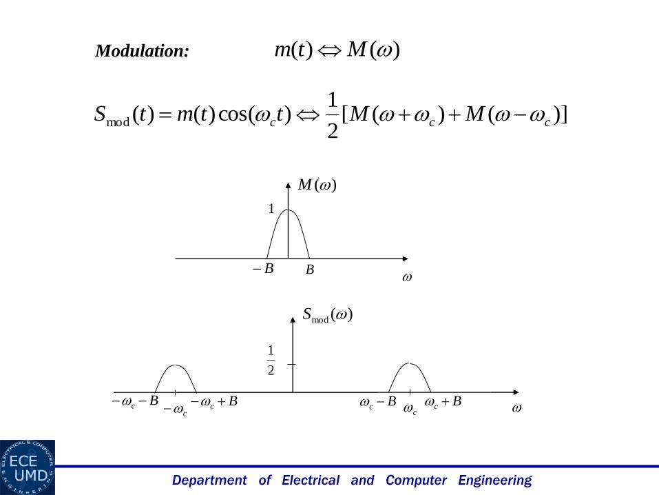
Modulation: )()( Mtm
)]()([2
1)cos()()(mod ccc MMttmtS
)(mod S
c
2
1
1
Bc Bc Bc Bc
Department of Electrical and Computer Engineering
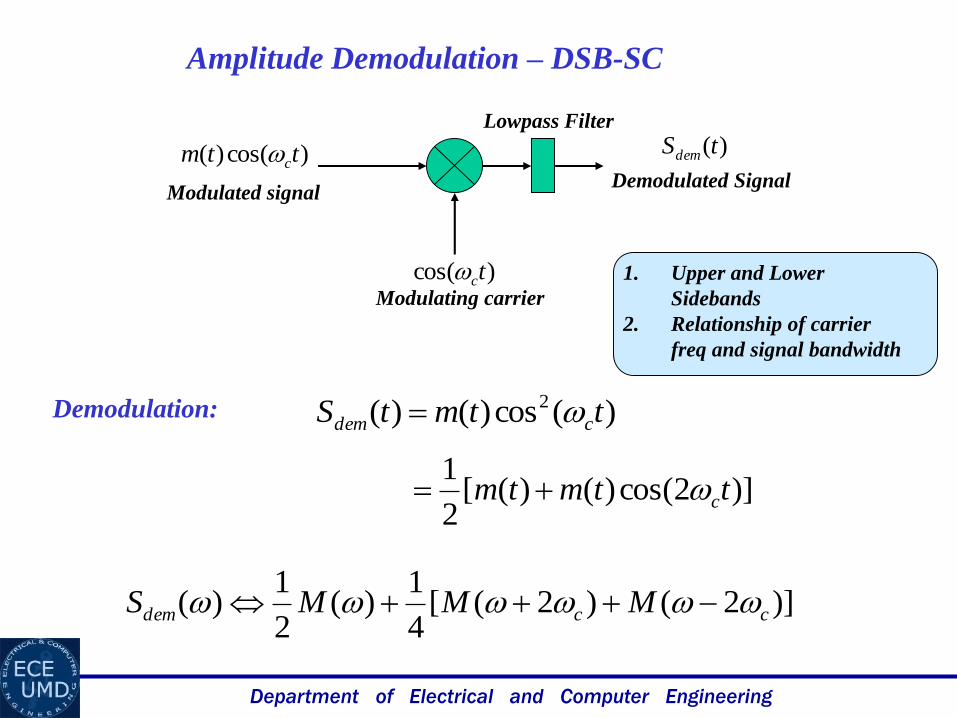
Demodulation: )(cos)()( 2 ttmtS cdem
)]2cos()()([2
1ttmtm c
)]2()2([4
1)(
2
1)( ccdem MMMS
Amplitude Demodulation – DSB-SC
)cos( tc
)cos()( ttm c
Modulated signalDemodulated Signal
Modulating carrier
)(tSdem
Lowpass Filter
1. Upper and Lower
Sidebands
2. Relationship of carrier
freq and signal bandwidth
Department of Electrical and Computer Engineering
c
)(mod S
c
2
1
Bc Bc Bc Bc
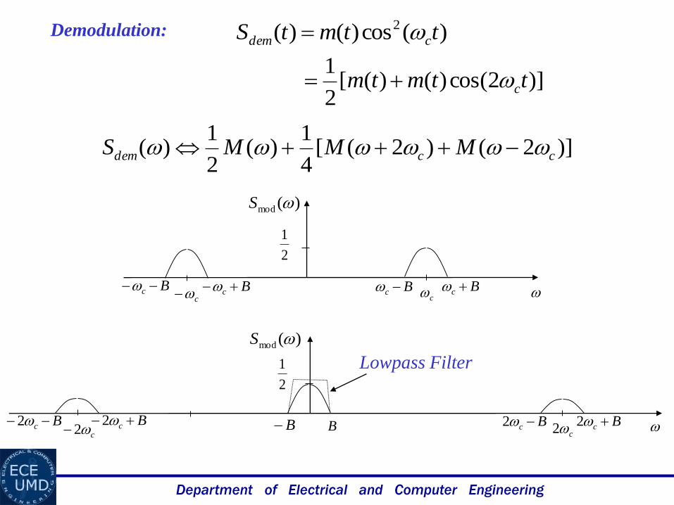
Demodulation: )(cos)()( 2 ttmtS cdem
)]2cos()()([2
1ttmtm c
)]2()2([4
1)(
2
1)( ccdem MMMS
)(mod S
c2
2
1
Bc 2Bc 2Bc 2c2BB Bc 2
Lowpass Filter
Department of Electrical and Computer Engineering
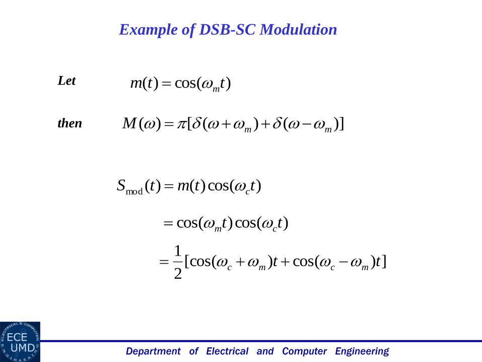
Example of DSB-SC Modulation
Let )cos()( ttm m
)]()([)( mmM
)cos()()(mod ttmtS c
)cos()cos( tt cm
])cos()[cos(2
1tt mcmc
then

Department of Electrical and Computer Engineering
)(cos)()( 2 ttmtS cdem
)(cos)cos( 2 tt cm
))2cos(1)(cos(2
1tt cm
)2cos()cos(2
1)cos(
2
1ttt cmm
Example of DSB-SC Demodulation

Department of Electrical and Computer Engineering
Frequency Conversion or Mixing
How to change carrier frequency from one frequency to another?
)()( Mtm
)]()([2
1)cos()()(mod ccc MMttmtS
c
)(mod S
c
2
1
Bc Bc Bc Bc
The Goal is to change toc I
)cos()( ttm c )cos()( ttm I
conversionupif cI
conversiondownif cI
Department of Electrical and Computer Engineering
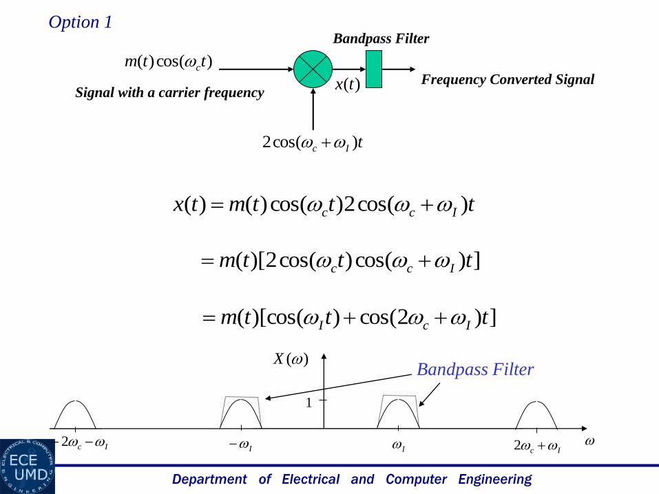
tIc )cos(2
)cos()( ttm c
Signal with a carrier frequencyFrequency Converted Signal
Bandpass FilterOption 1
tttmtx Icc )cos(2)cos()()(
])cos()cos(2)[( tttm Icc
])2cos())[cos(( tttm IcI
)(tx
I
)(X
I
1
Ic 2Ic 2
Bandpass Filter
Department of Electrical and Computer Engineering
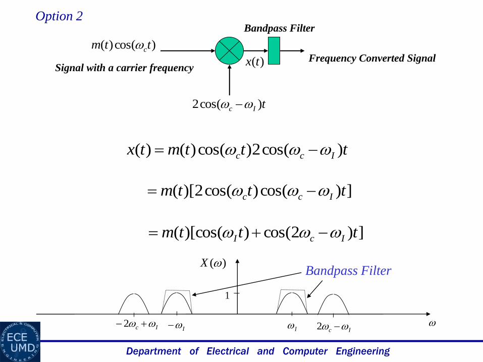
tIc )cos(2
)cos()( ttm c
Signal with a carrier frequencyFrequency Converted Signal
Bandpass FilterOption 2
tttmtx Icc )cos(2)cos()()(
])cos()cos(2)[( tttm Icc
])2cos())[cos(( tttm IcI
)(tx
I
)(X
I
1
Ic 2Ic 2
Bandpass Filter
Department of Electrical and Computer Engineering
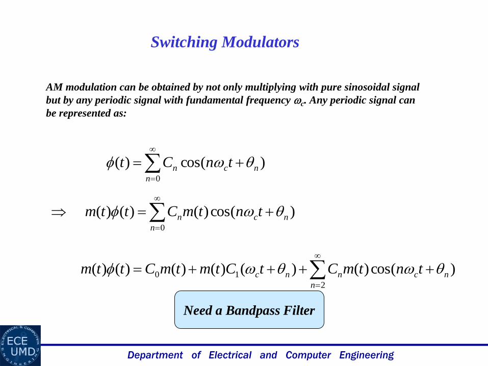
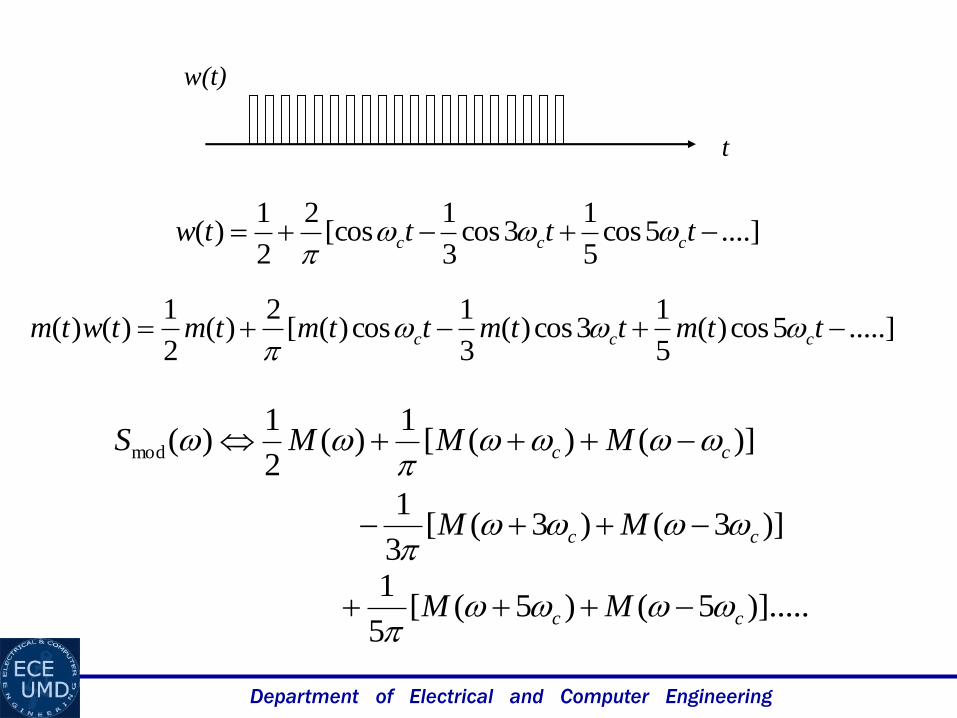
Switching Modulators
AM modulation can be obtained by not only multiplying with pure sinosoidal signal
but by any periodic signal with fundamental frequency c. Any periodic signal can
be represented as:
)cos()(0
nc
n
n tnCt
)cos()()()(0
nc
n
n tntmCttm
)cos()()()()()()(2
10 nc
n
nnc tntmCtCtmtmCttm
Need a Bandpass Filter
Department of Electrical and Computer Engineering
t
w(t)
....]5cos5
13cos
3
1[cos
2
2
1)( ttttw ccc
.....]5cos)(5
13cos)(
3
1cos)([
2)(
2
1)()( ttmttmttmtmtwtm ccc
)]()([1
)(2
1)(mod cc MMMS
)]3()3([3
1cc MM
)].....5()5([5
1cc MM
Department of Electrical and Computer Engineering
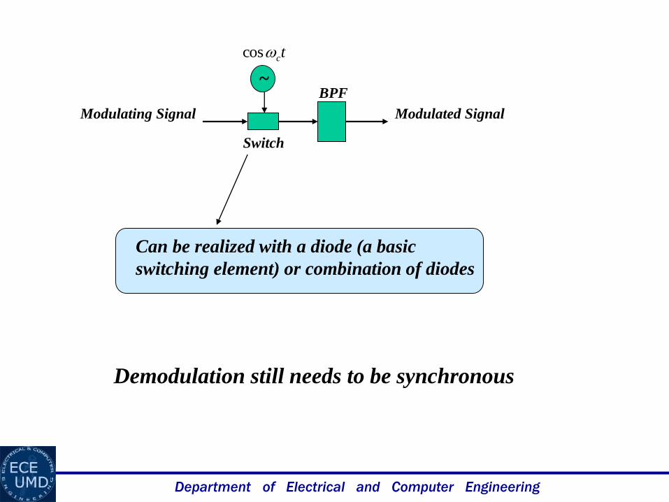
Modulating Signal Modulated Signal
BPF
Switch
Can be realized with a diode (a basic
switching element) or combination of diodes
Demodulation still needs to be synchronous
~
tccos
Department of Electrical and Computer Engineering
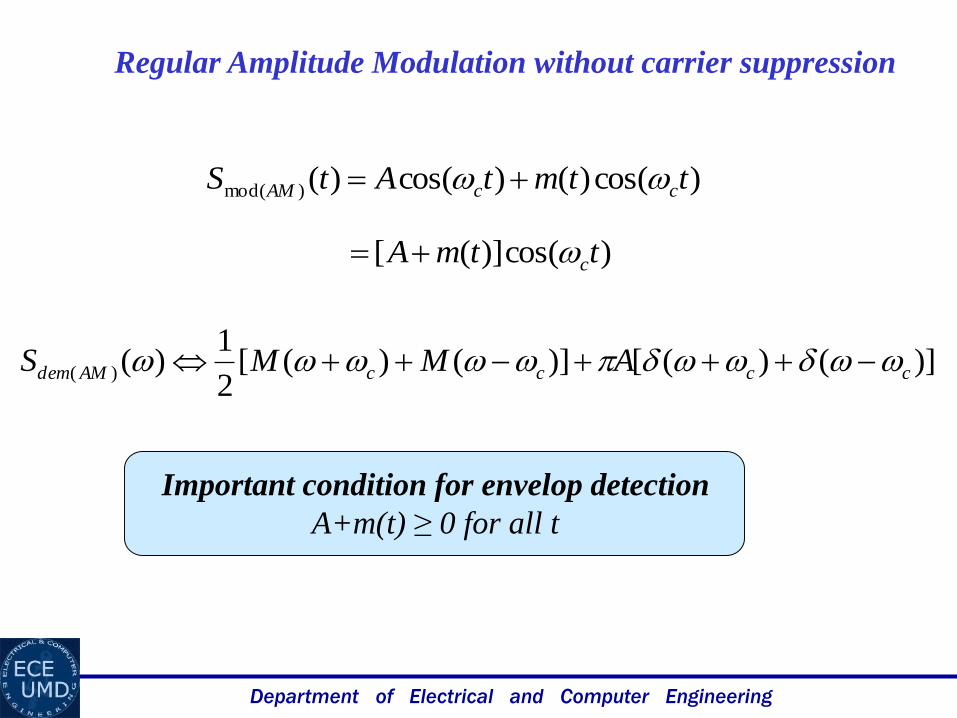
)cos()()cos()()mod( ttmtAtS ccAM
Regular Amplitude Modulation without carrier suppression
)cos()]([ ttmA c
)]()([)]()([2
1)()( ccccAMdem AMMS
Important condition for envelop detection
A+m(t) ≥ 0 for all t
Department of Electrical and Computer Engineering
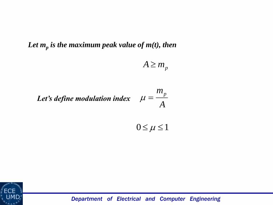
Let mp is the maximum peak value of m(t), then
pmA
A
mp
10
Let’s define modulation index
Department of Electrical and Computer Engineering
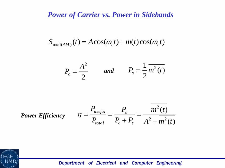
Power of Carrier vs. Power in Sidebands
)cos()()cos()()mod( ttmtAtS ccAM
2
2APc )(
2
1 2 tmPs
)(
)(22
2
tmA
tm
PP
P
P
P
sc
s
total
useful
and
Power Efficiency

Department of Electrical and Computer Engineering
)cos()()cos()()mod( ttmtAtS ccAM
)cos()( tBtm m
)cos()cos()cos()()mod( ttBtAtS cmcAM
)cos()]cos([ ttBA cm
Let
ABA
B
A
mp
)cos()]cos([)()mod( ttAAtS cmAM
)cos()]cos(1[ ttA cm
Department of Electrical and Computer Engineering
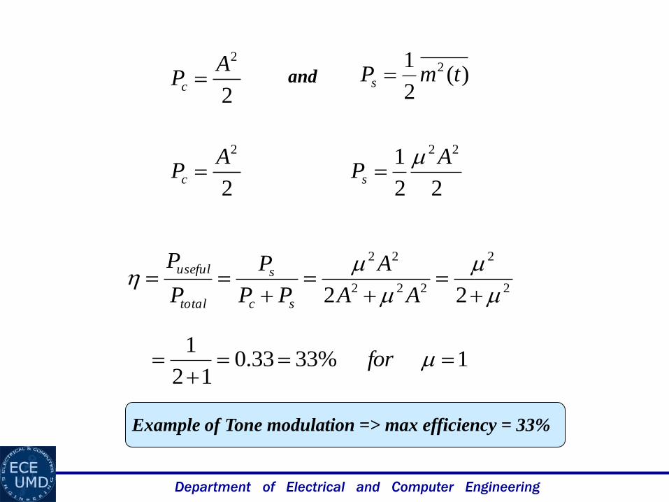
Example of Tone modulation => max efficiency = 33%
2
2APc )(
2
1 2 tmPs and
2
2APc
22
1 22 APs
2
2
222
22
22
AA
A
PP
P
P
P
sc
s
total
useful
1%3333.012
1
for
Department of Electrical and Computer Engineering
Generation of AM signals
Generation of AM signals is the same as generation f AM-SC
signals, the only difference is that m(t) is replaced by [A+m(t)]
Demodulation of AM signals
Two commonly used methods are:
1. Rectifier Detection – synchronous demodulation
2. Envelop Detection – very simple detection

Department of Electrical and Computer Engineering
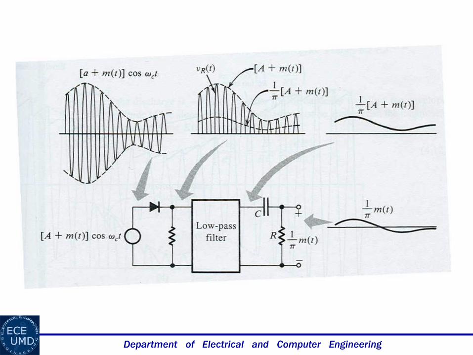
Rectifier Detector
)cos()]([1 ttmAv c+
-)()}cos()]({[2 twttmAv c
2v
1v
....]5cos5
23cos
3
2cos
2
2
1)[cos()]([ tttttmA cccc
termsfrequencyhighertmA )]([1
LPF
3v
)]([1
3 tmAv
4v
)(1
4 tmv
....]5cos5
23cos
3
2
2
1)[cos()]([cos
2*)cos()]([ ttttmAtttmA ccccc
Department of Electrical and Computer Engineering
Department of Electrical and Computer Engineering
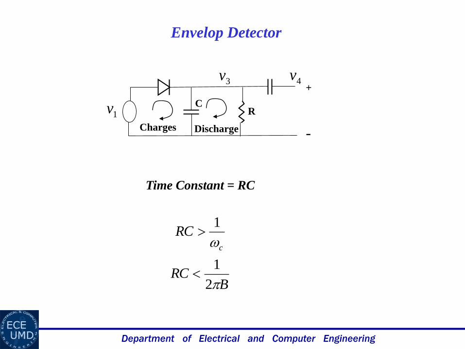
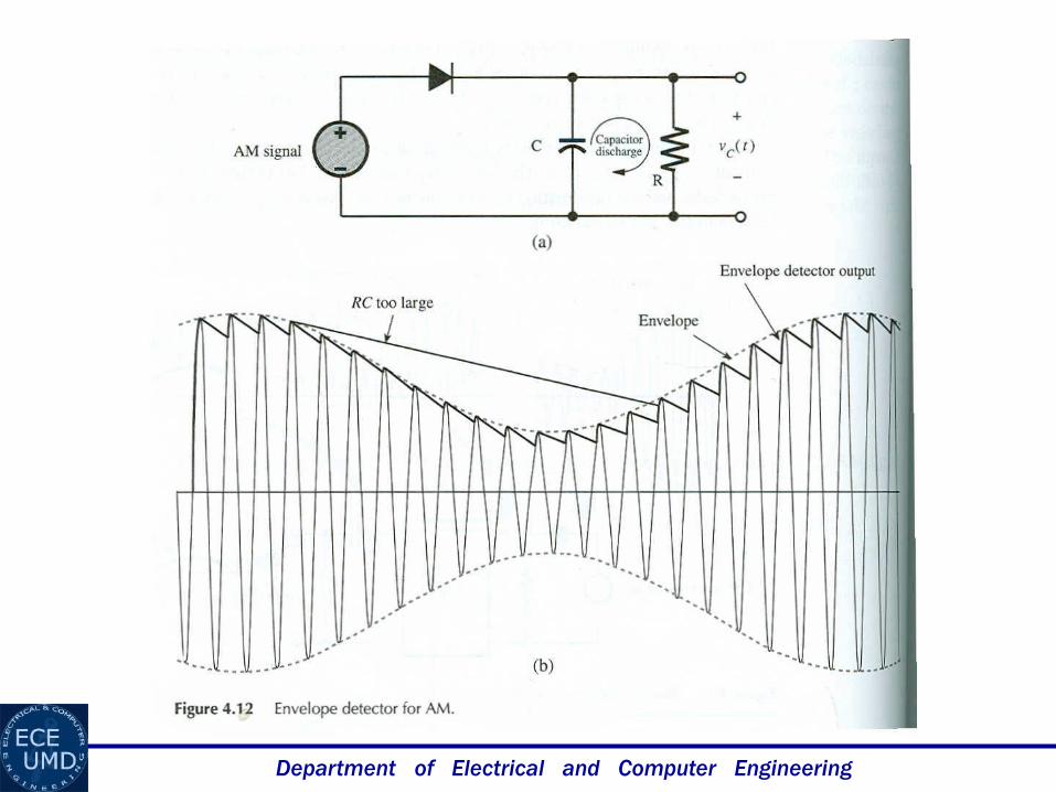
Envelop Detector
+
-
1vCharges Discharge
CR
Time Constant = RC
c
RC
1
BRC
2
1
3v 4v
Department of Electrical and Computer Engineering
Department of Electrical and Computer Engineering
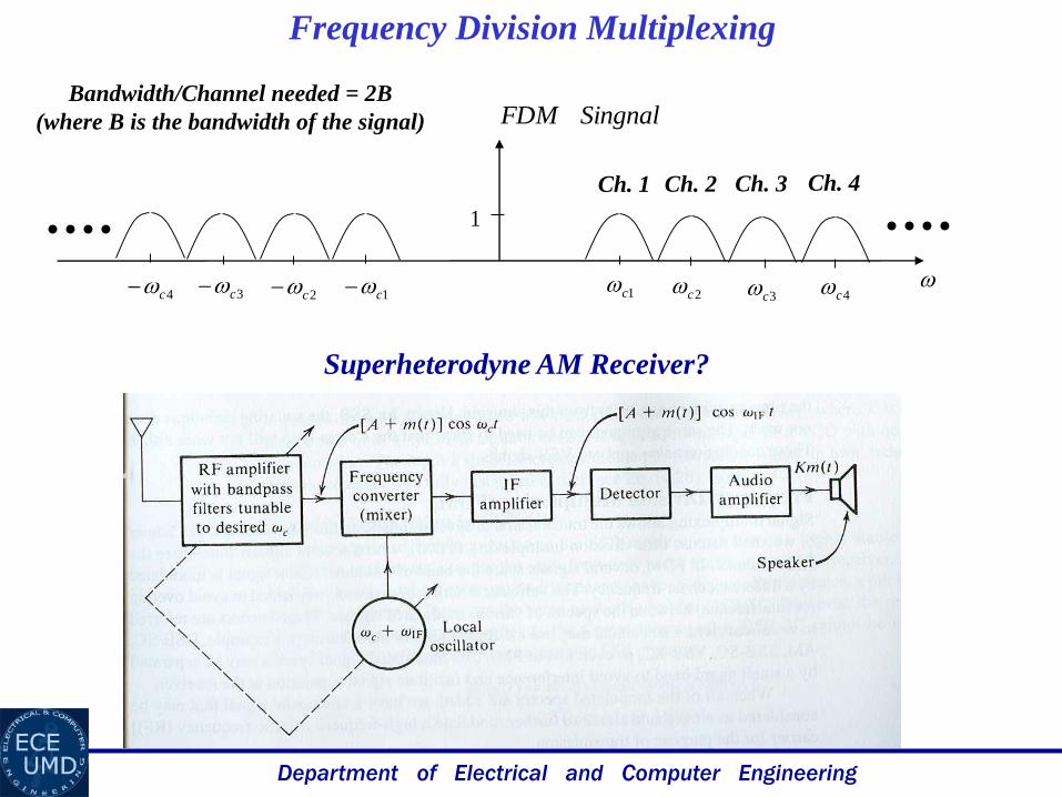
Frequency Division Multiplexing
1c
SingnalFDM
1c
1
2c 3c 4c2c3c4c
Ch. 1 Ch. 2 Ch. 3 Ch. 4
Bandwidth/Channel needed = 2B
(where B is the bandwidth of the signal)
Superheterodyne AM Receiver?
Department of Electrical and Computer Engineering
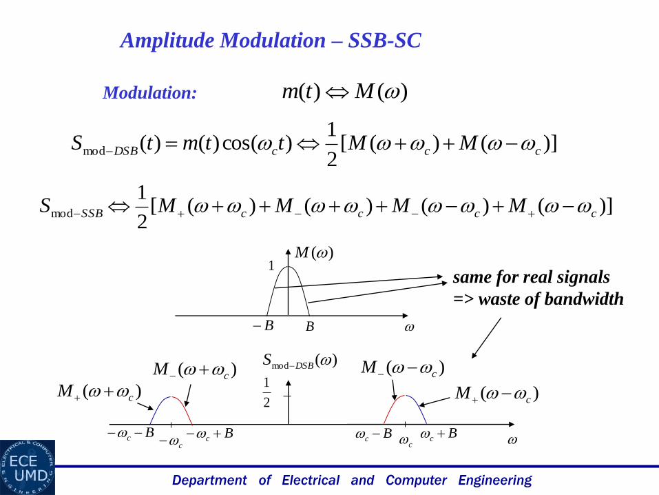
Amplitude Modulation – SSB-SC
Modulation: )()( Mtm
)]()([2
1)cos()()(mod cccDSB MMttmtS
)]()()()([2
1mod ccccSSB MMMMS
c c
2
1
Bc Bc Bc Bc
)(M
BB
)(mod DSBS
1
)( cM
)( cM )( cM
)( cM
same for real signals
=> waste of bandwidth
Department of Electrical and Computer Engineering
c c
2
1
Bc Bc Bc Bc
)(mod DSBS
)( cM
)( cM )( cM
)( cM
c c
2
1
Bc Bc Bc Bc
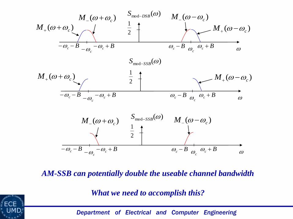
)(mod SSBS
)( cM )( cM
c c
2
1
Bc Bc Bc Bc
)(mod SSBS )( cM )( cM
AM-SSB can potentially double the useable channel bandwidth
What we need to accomplish this?
Department of Electrical and Computer Engineering
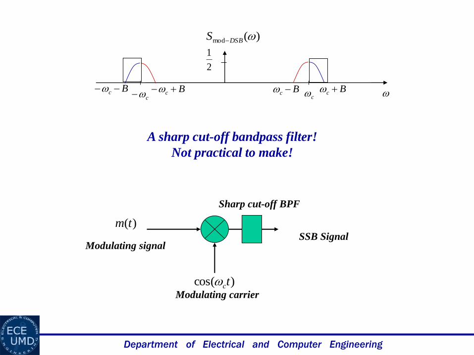
)(tm
)cos( tc
Modulating signalSSB Signal
Modulating carrier
Sharp cut-off BPF
c c
2
1
Bc Bc Bc Bc
)(mod DSBS
A sharp cut-off bandpass filter!
Not practical to make!
Department of Electrical and Computer Engineering
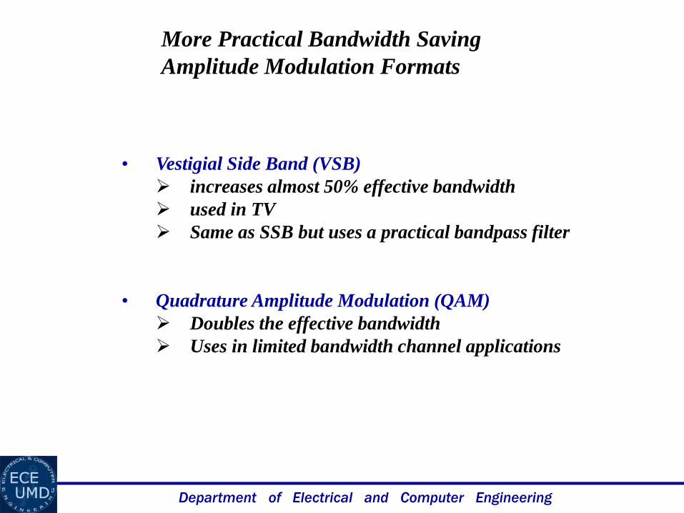
More Practical Bandwidth Saving
Amplitude Modulation Formats
• Vestigial Side Band (VSB)
increases almost 50% effective bandwidth
used in TV
Same as SSB but uses a practical bandpass filter
• Quadrature Amplitude Modulation (QAM)
Doubles the effective bandwidth
Uses in limited bandwidth channel applications
Department of Electrical and Computer Engineering
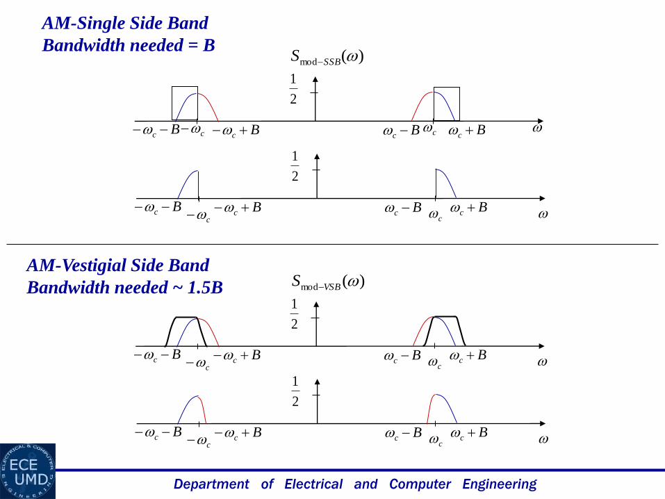
c c
2
1
Bc Bc Bc Bc
)(mod SSBS
c c
2
1
Bc Bc Bc Bc
)(mod VSBS
c c
2
1
Bc Bc Bc Bc
c c
2
1
Bc Bc Bc Bc
AM-Single Side Band
Bandwidth needed = B
AM-Vestigial Side Band
Bandwidth needed ~ 1.5B
Department of Electrical and Computer Engineering
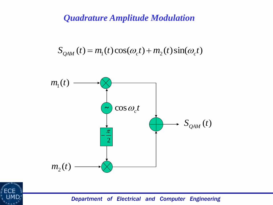
Quadrature Amplitude Modulation
)sin()()cos()()( 21 ttmttmtS ccQAM
2
~
)(1 tm
)(2 tm
tccos
)(tSQAM
Department of Electrical and Computer Engineering
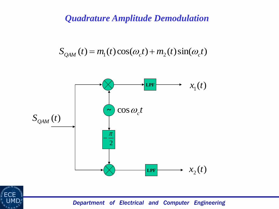
Quadrature Amplitude Demodulation
)sin()()cos()()( 21 ttmttmtS ccQAM
2
~ tccos
LPF )(1 tx
)(2 tx
)(tSQAM
LPF

Department of Electrical and Computer Engineering
)cos()]sin()()cos()([)( 211 tttmttmtx ccc
)sin()()cos()()( 21 ttmttmtS ccQAM
)cos()sin()()(cos)( 2
2
1 tttmttm ccc
)cos()sin()()2cos()(2
1)(
2
1211 tttmttmtm ccc
will be filtered by lowpass filter
Department of Electrical and Computer Engineering
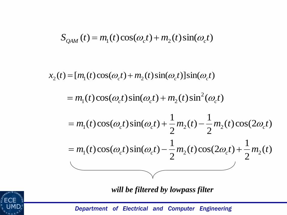
)sin()]sin()()cos()([)( 212 tttmttmtx ccc
)sin()()cos()()( 21 ttmttmtS ccQAM
)(sin)()sin()cos()( 2
21 ttmtttm ccc
)2cos()(2
1)(
2
1)sin()cos()( 221 ttmtmtttm ccc
will be filtered by lowpass filter
)(2
1)2cos()(
2
1)sin()cos()( 221 tmttmtttm ccc
Department of Electrical and Computer Engineering
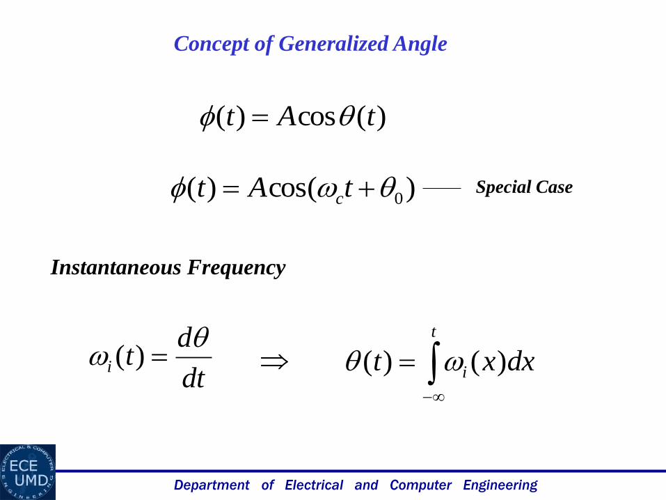
Concept of Generalized Angle
)(cos)( tAt
)cos()( 0 tAt cSpecial Case
dt
dti
)(
t
i dxxt )()(
Instantaneous Frequency
Department of Electrical and Computer Engineering
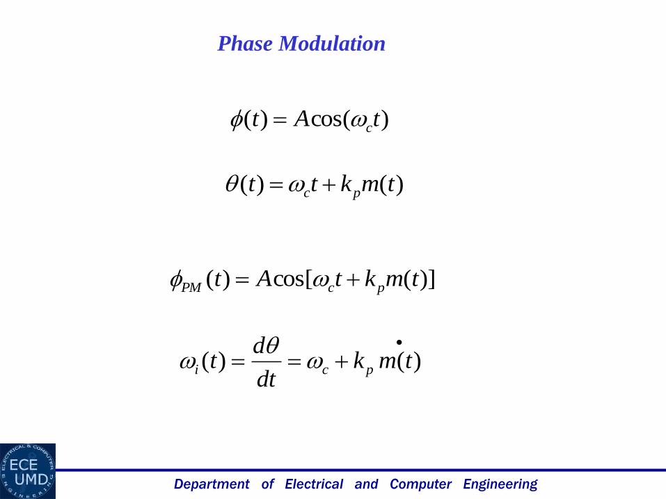
Phase Modulation
)cos()( tAt c
)()( tmktt pc
)](cos[)( tmktAt pcPM
)()( tmkdt
dt pci
Department of Electrical and Computer Engineering
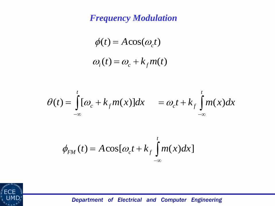
Frequency Modulation
)cos()( tAt c
)()( tmkt fci
t
fc dxxmkt )]([)(
t
fc dxxmkt )(
])(cos[)(
t
fcFM dxxmktAt
Department of Electrical and Computer Engineering
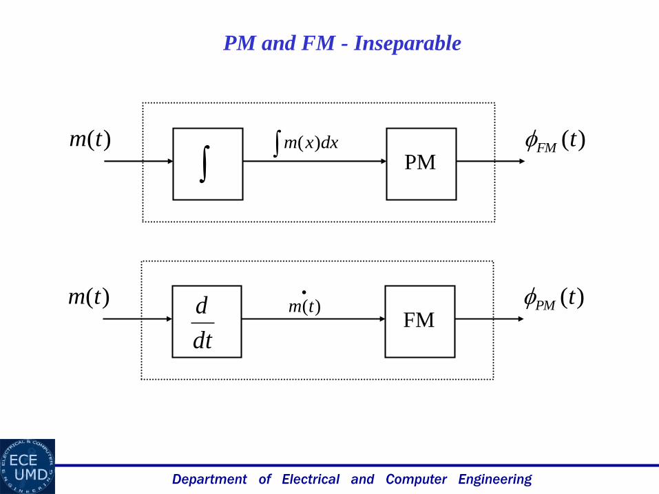
PM and FM - Inseparable
PM)(tm dxxm )(
)(tFM
FM)(tm
)(tm
dt
d )(tPM
Department of Electrical and Computer Engineering
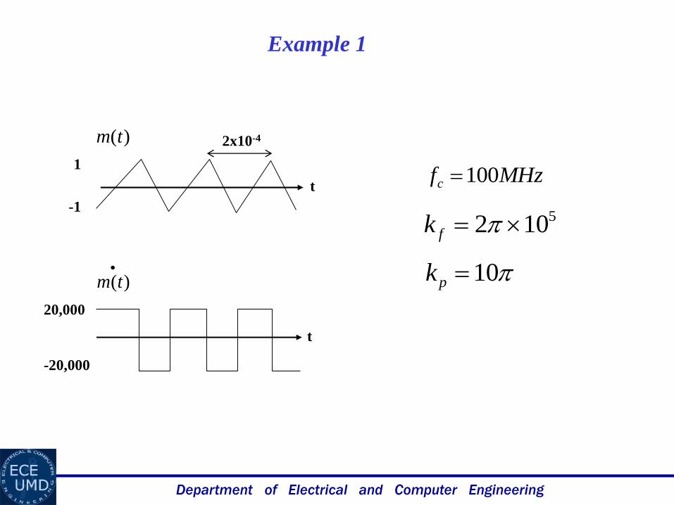
Example 1
)(tm
)(tm
1
-1
2x10⁻⁴
t
t
20,000
-20,000
5102 fk
10pk
MHzfc 100
Department of Electrical and Computer Engineering
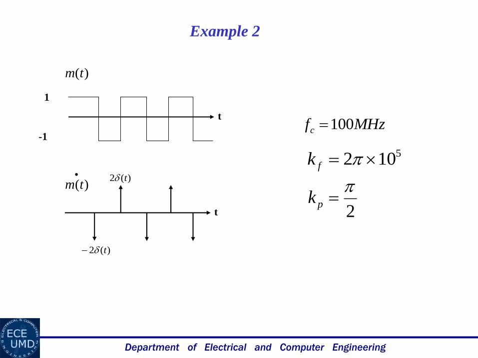
Example 2
)(tm
t
1
-1
5102 fk
2
pk
)(tm
t
)(2 t
)(2 t
MHzfc 100
Department of Electrical and Computer Engineering
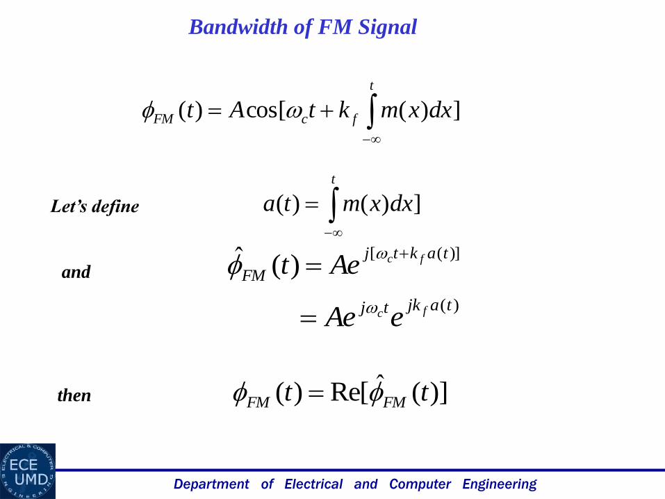
Bandwidth of FM Signal
])(cos[)(
t
fcFM dxxmktAt
])()(
t
dxxmta
)]([)(ˆ taktj
FMfcAet
)(tajktj fc eAe
Let’s define
and
then )](ˆRe[)( tt FMFM
Department of Electrical and Computer Engineering
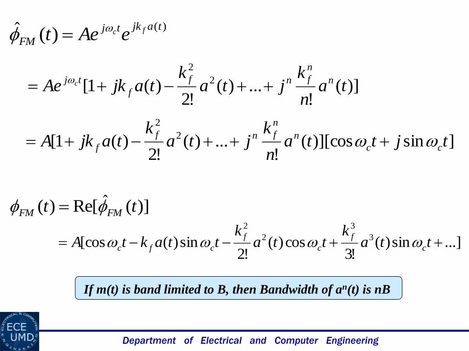
)()(ˆ tajktj
FMfc eAet
)](!
...)(!2
)(1[ 2
2
tan
kjta
ktajkAe n
n
fnf
f
tj c
]sin)][cos(!
...)(!2
)(1[ 2
2
tjttan
kjta
ktajkA cc
n
n
fnf
f
)](ˆRe[)( tt FMFM
...]sin)(!3
cos)(!2
sin)([cos 3
3
2
2
ttak
ttak
ttaktA c
f
c
f
cfc
If m(t) is band limited to B, then Bandwidth of an(t) is nB
Department of Electrical and Computer Engineering
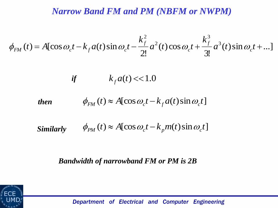
...]sin)(!3
cos)(!2
sin)([cos)( 3
3
2
2
ttak
ttak
ttaktAt c
f
c
f
cfcFM
0.1)( tak fif
]sin)([cos)( ttaktAt cfcFM then
]sin)([cos)( ttmktAt cpcPM Similarly
Narrow Band FM and PM (NBFM or NWPM)
Bandwidth of narrowband FM or PM is 2B
Department of Electrical and Computer Engineering
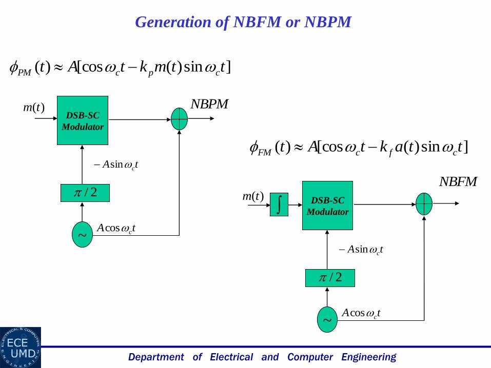
Generation of NBFM or NBPM
]sin)([cos)( ttaktAt cfcFM
]sin)([cos)( ttmktAt cpcPM
tA ccos
NBPM)(tm
~
2/
DSB-SC
Modulator
tA csin
tA ccos
NBFM)(tm
~
2/
DSB-SC
Modulator
tA csin
Department of Electrical and Computer Engineering
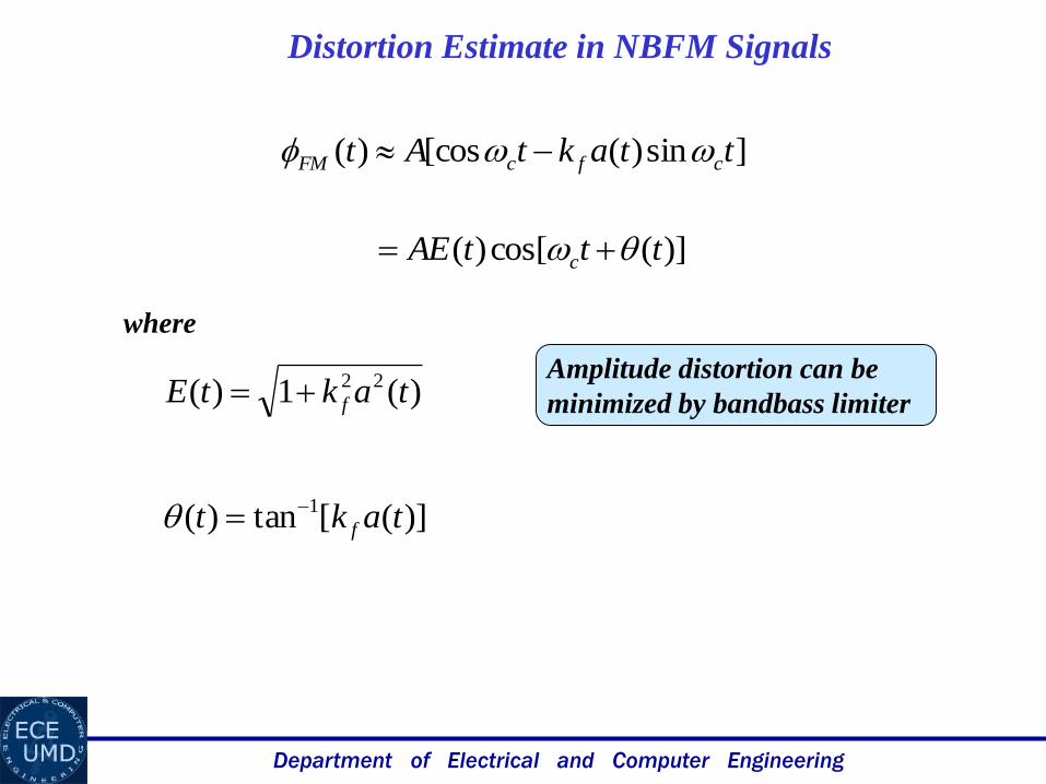
]sin)([cos)( ttaktAt cfcFM
Distortion Estimate in NBFM Signals
)](cos[)( tttAE c
)(1)( 22 taktE f
)]([tan)( 1 takt f
where
Amplitude distortion can be
minimized by bandbass limiter
Department of Electrical and Computer Engineering
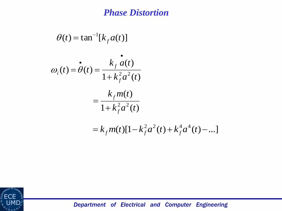
Phase Distortion
)]([tan)( 1 takt f
)(1
)()()(
22 tak
taktt
f
f
i
)(1
)(22 tak
tmk
f
f
...])()(1)[( 4422 taktaktmk fff
Department of Electrical and Computer Engineering
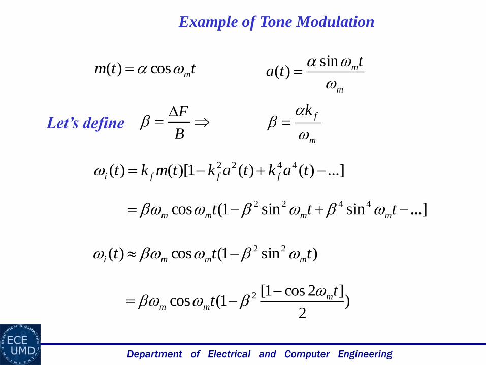
Example of Tone Modulation
...])()(1)[()( 4422 taktaktmkt fffi
ttm m cos)(
m
mtta
sin)(
m
fk
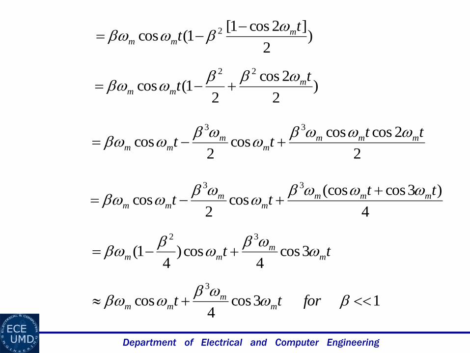
...]sinsin1(cos 4422 ttt mmmm
)sin1(cos)( 22 ttt mmmi
)2
]2cos1[1(cos 2 t
t mmm
B
FLet’s define
Department of Electrical and Computer Engineering
tt mm
mm
3cos4
cos)4
1(32
)2
]2cos1[1(cos 2 t
t mmm
)2
2cos
21(cos
22 tt m
mm
2
2coscoscos
2cos
33 tttt mmm
mm
mm
4
)3cos(coscos
2cos
33 tttt mmm
mm
mm
13cos4
cos3
fortt mm
mm
Department of Electrical and Computer Engineering
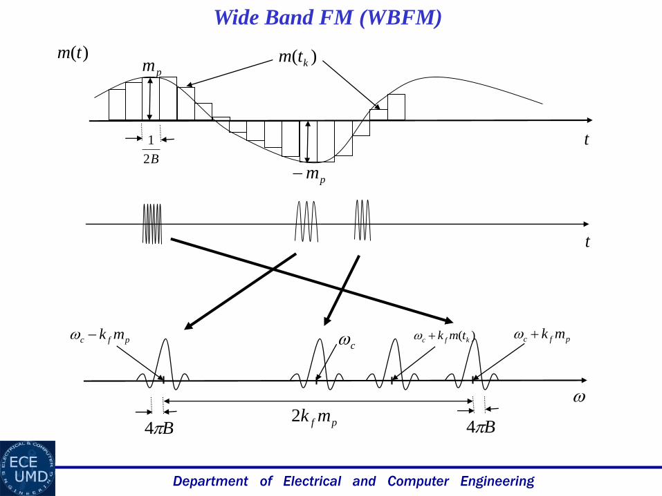
B4 B4
pfc mk pfc mk)( kfc tmk
)( ktmpm
pm
t
)(tm
pf mk2
B2
1
t
Wide Band FM (WBFM)
c
Department of Electrical and Computer Engineering
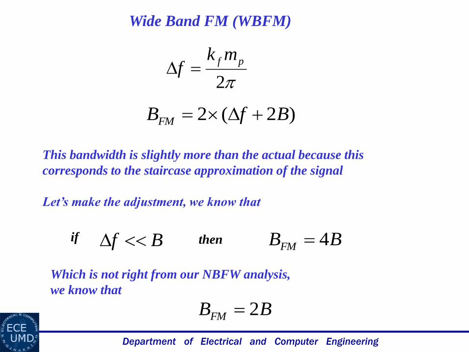
Wide Band FM (WBFM)
)2(2 BfBFM
2
pf mkf
Bf BBFM 4if then
This bandwidth is slightly more than the actual because this
corresponds to the staircase approximation of the signal
Let’s make the adjustment, we know that
Which is not right from our NBFW analysis,
we know that
BBFM 2
Department of Electrical and Computer Engineering
Wide Band FM (WBFM)
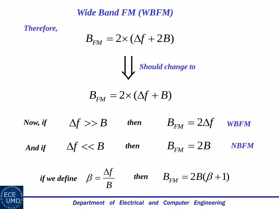
Bf fBFM 2
B
f )1(2 BBFMif we define then
)(2 BfBFM
Now, if then
)2(2 BfBFM Therefore,
Should change to
And if Bf BBFM 2then
WBFM
NBFM
Department of Electrical and Computer Engineering
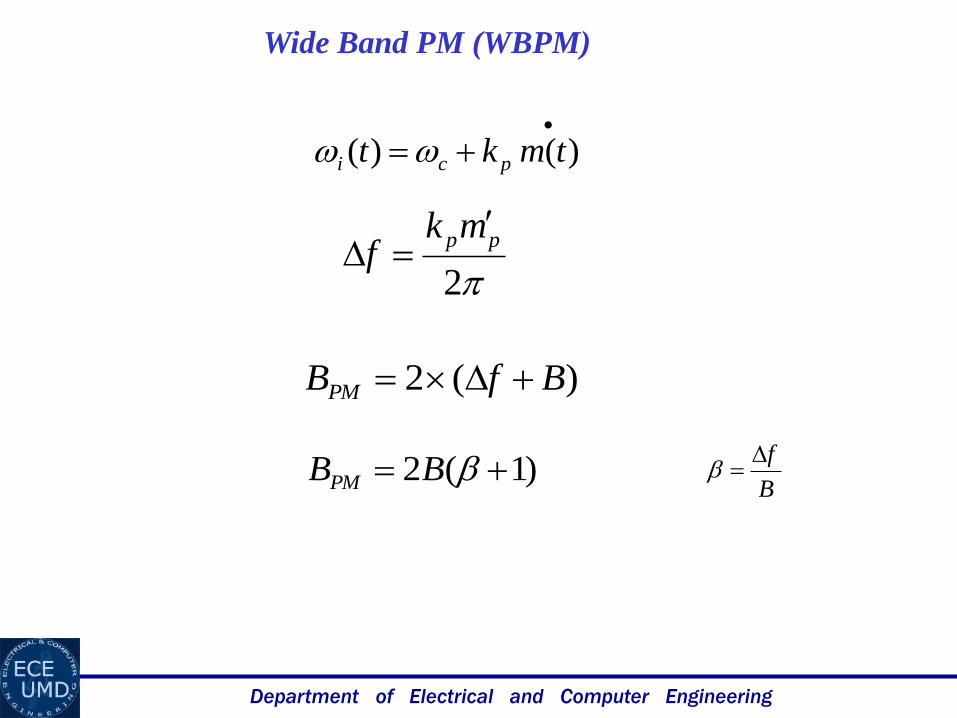
Wide Band PM (WBPM)
)(2 BfBPM
2
ppmkf
)1(2 BBPM
)()( tmkt pci
B
f
Department of Electrical and Computer Engineering
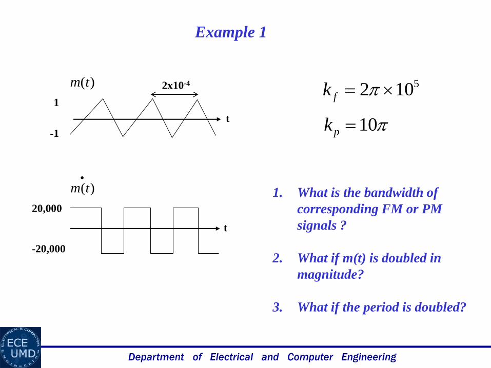
Example 1
)(tm
)(tm
1
-1
2x10⁻⁴
t
t
20,000
-20,000
5102 fk
10pk
1. What is the bandwidth of
corresponding FM or PM
signals ?
2. What if m(t) is doubled in
magnitude?
3. What if the period is doubled?
Department of Electrical and Computer Engineering
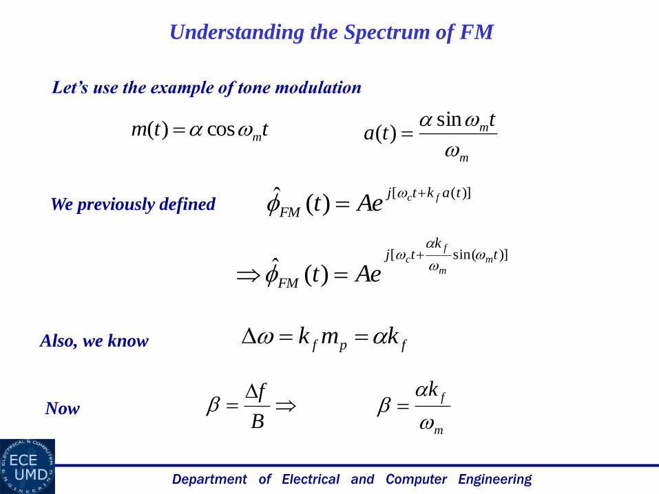
Understanding the Spectrum of FM
)]([)(ˆ taktj
FMfcAet
We previously defined
Also, we know
ttm m cos)(
m
mtta
sin)(
)]sin([
)(ˆt
ktj
FM
mm
fc
Aet
fpf kmk
m
fk
B
fNow
Let’s use the example of tone modulation
Department of Electrical and Computer Engineering
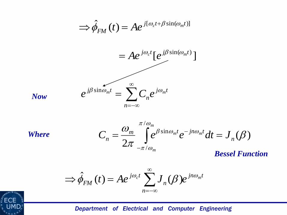
)]sin([)(ˆ ttj
FMmcAet
][)sin( tjtj mc eAe
n
tj
n
tj mm eCe sin
Now
Where )(2
/
/
sin
n
tjntmn JdteeC
m
m
mm
tjn
n
n
tj
FMmc eJAet
)()(ˆ
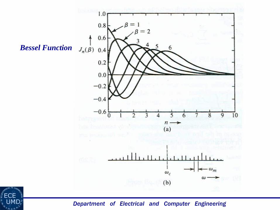
Bessel Function
Department of Electrical and Computer Engineering
tjn
n
n
tj
FMmc eJAet
)()(ˆ
)()(
tntj
n
nmceJA
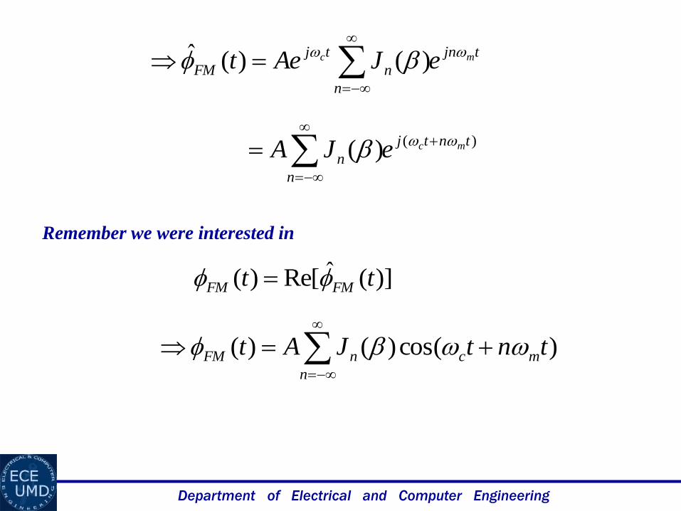
)](ˆRe[)( tt FMFM
Remember we were interested in
)cos()()( tntJAt mc
n
nFM
Department of Electrical and Computer Engineering
Bessel Function
Department of Electrical and Computer Engineering
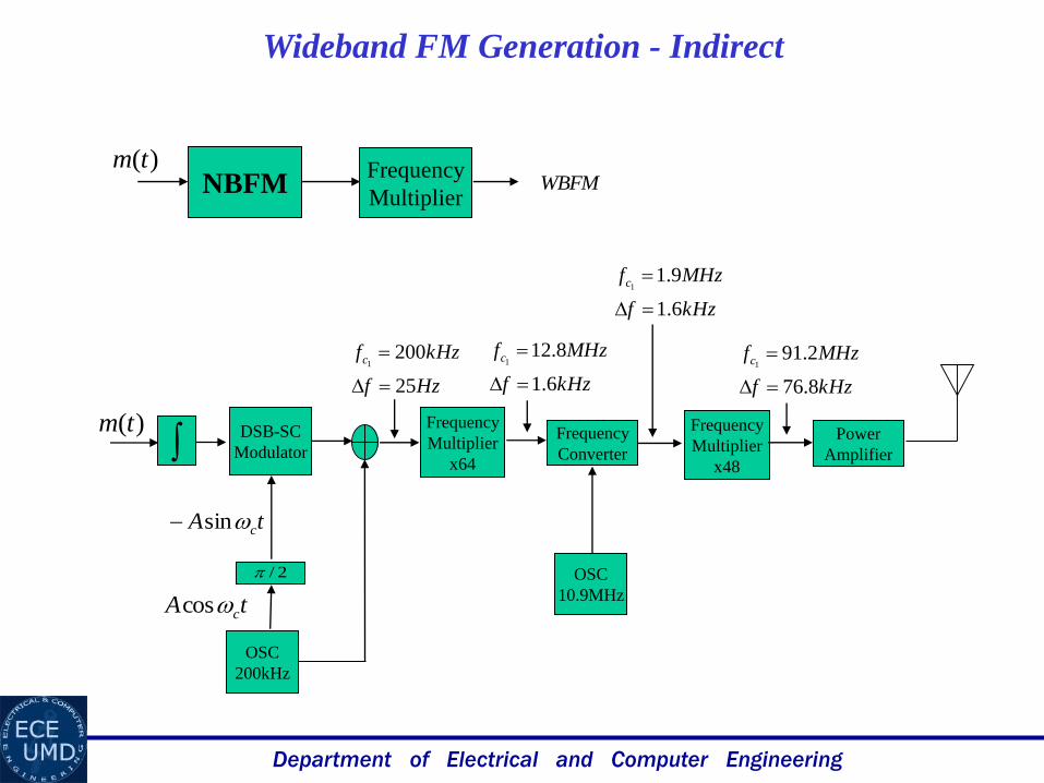
tA ccos
)(tm
2/
DSB-SC
Modulator
tA csin
OSC
200kHz
Frequency
Multiplier
x64
Frequency
Multiplier
x48
Frequency
Converter
Power
Amplifier
OSC
10.9MHz
Hzf
kHzfc
25
2001
kHzf
MHzfc
6.1
8.121
kHzf
MHzfc
6.1
9.11
kHzf
MHzfc
8.76
2.911
Wideband FM Generation - Indirect
NBFMFrequency
MultiplierWBFM
)(tm
Department of Electrical and Computer Engineering
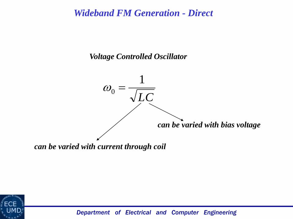
Wideband FM Generation - Direct
Voltage Controlled Oscillator
LC
10
can be varied with bias voltage
can be varied with current through coil

Department of Electrical and Computer Engineering
Demodulation of FM
])(cos[)(
t
fcFM dxxmktAt
]})(cos[{)(
t
fcFM dxxmktAdt
dt
])(sin[)]([
t
fcfc dxxmkttmkA
Envelope
Detection
)(tFM
dt
d )]([ tmkA fc

Department of Electrical and Computer Engineering
Demodulation of PM
)](cos[)( tmktAt pcPM
)]}(cos[{)( tmktAdt
dt pcPM
)](sin[)]([ tmkttmkA pcpc
Envelope
Detection
)(tFM
dt
d
)]([ tmkA pc
)(tmAk p
)(tmAk pC
Department of Electrical and Computer Engineering
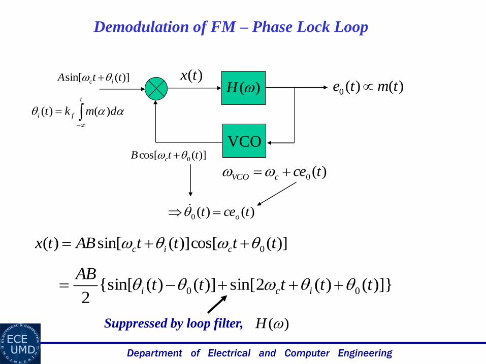
Demodulation of FM – Phase Lock Loop
VCO
)(H)(tx
)()(0 tmte )](sin[ ttA ic
)](cos[ 0 ttB c
)(0 tcecVCO
)](cos[)](sin[)( 0 ttttABtx cic
)]}()(2sin[)]()({sin[2
00 tttttAB
ici
t
fi dmkt )()(
Suppressed by loop filter, )(H
)()(0 tcet o
Department of Electrical and Computer Engineering
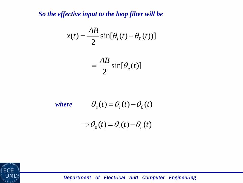
So the effective input to the loop filter will be
))]()(sin[2
)( 0 ttAB
tx i
)()()( 0 ttt ie where
)](sin[2
tAB
e
)()()(0 ttt ei
Department of Electrical and Computer Engineering
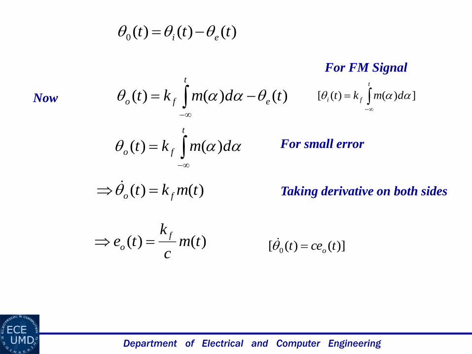
)]()([ 0 tcet o
)()()(0 ttt ei
])()([
t
fi dmkt )()()( tdmkt e
t
fo
)()( tmkt fo
For small error
Now
)()( tmc
kte
f
o
For FM Signal
t
fo dmkt )()(
Taking derivative on both sides
Department of Electrical and Computer Engineering
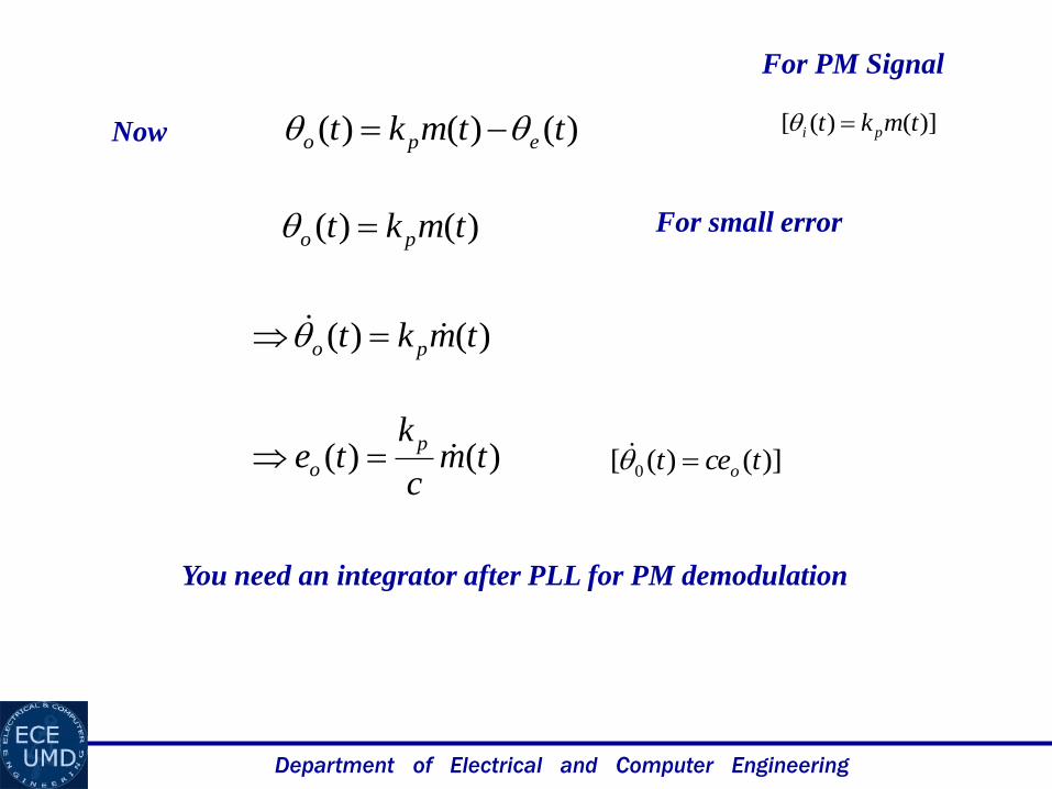
)]()([ 0 tcet o
)]()([ tmkt pi )()()( ttmkt epo
)()( tmkt po
For small error
Now
)()( tmc
kte
p
o
For PM Signal
You need an integrator after PLL for PM demodulation
)()( tmkt po
Department of Electrical and Computer Engineering
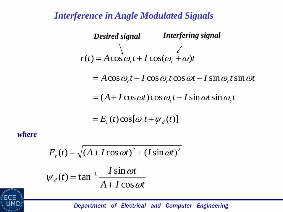
Interference in Angle Modulated Signals
tItAtr cc )cos(cos)(
Desired signal Interfering signal
ttIttItA ccc sinsincoscoscos
)](cos[)( tttE dcr
ttIttIA cc sinsincos)cos(
22 )sin()cos()( tItIAtEr
tIA
tItd
cos
sintan)( 1
where
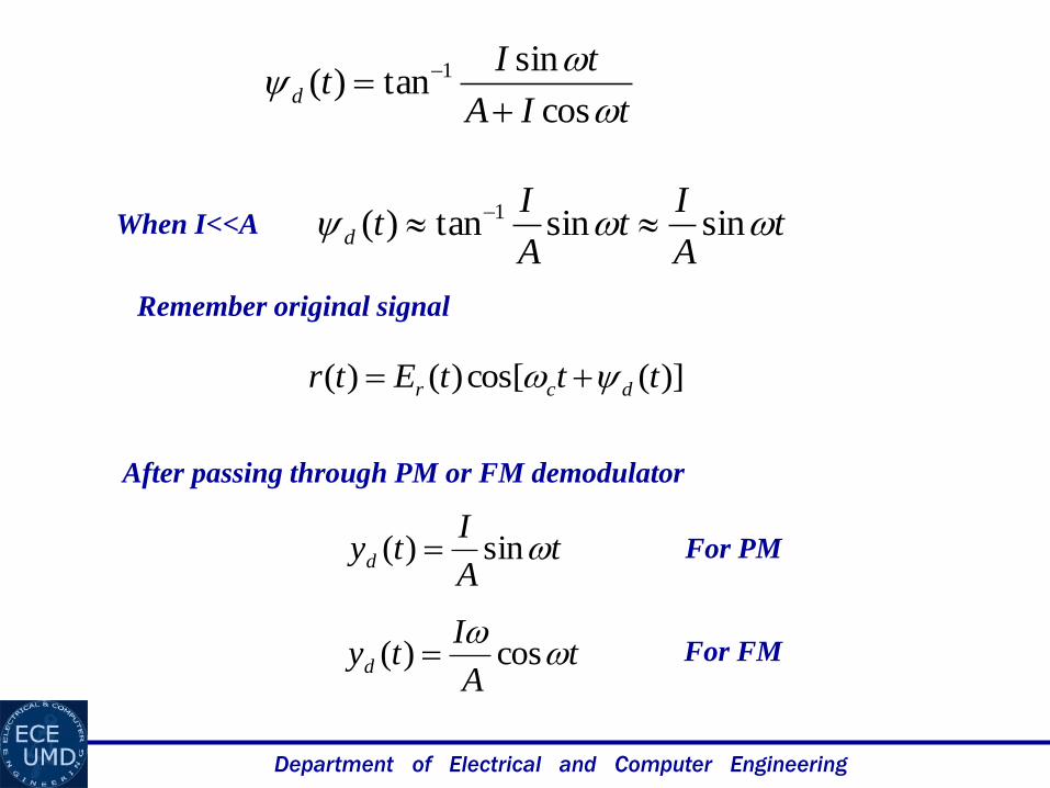
Department of Electrical and Computer Engineering
tA
It
A
Itd sinsintan)( 1
tIA
tItd
cos
sintan)( 1
When I<<A
)](cos[)()( tttEtr dcr
Remember original signal
tA
Ityd sin)(
tA
Ityd
cos)(
For PM
For FM
After passing through PM or FM demodulator
Department of Electrical and Computer Engineering
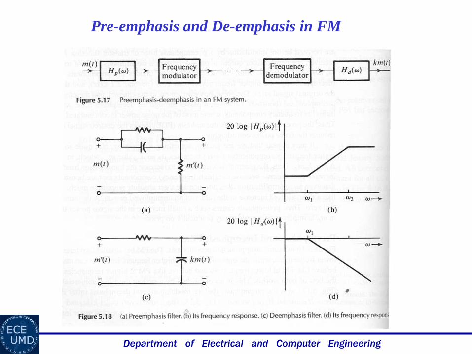
Pre-emphasis and De-emphasis in FM
Department of Electrical and Computer Engineering
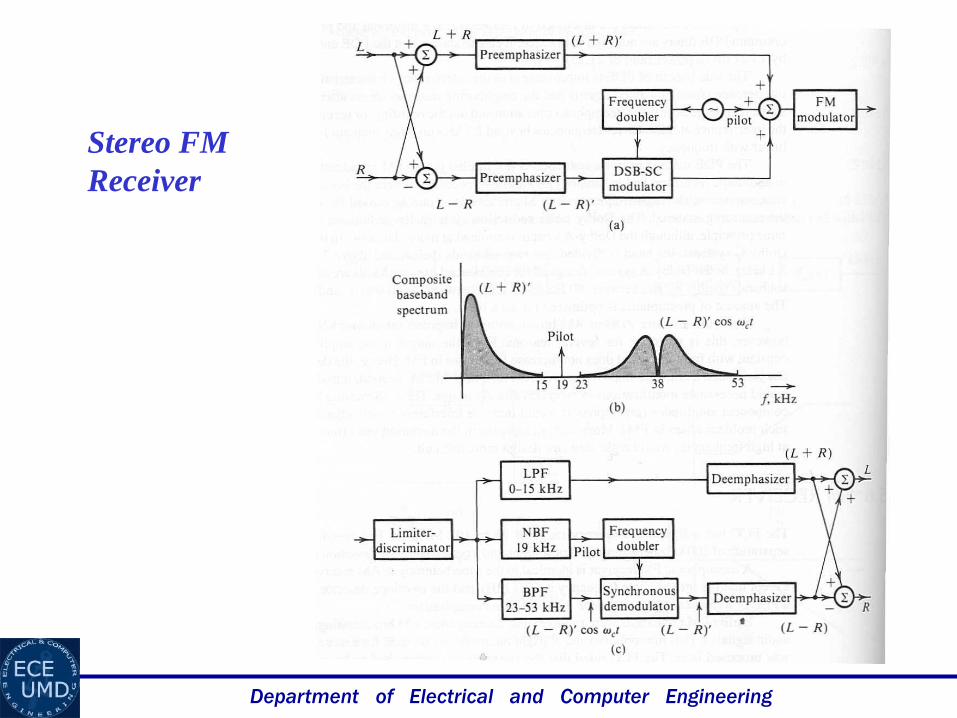
Stereo FM
Receiver