amplifiers - audio design · instructions. failure to heed the ... turn-off the amplifier when +12v...
TRANSCRIPT

Installation & Operation
AMPLIFIERS
P300X1 P300X2 P400X1
P400X2 P400X4 P500X1BD
P500X2 P600X4 P1000X1BD
P1000X2 P1000X5
32
Dear Customer,
Congratulations on your purchase of the world’s finest brand of car audio products. At Rockford Fosgate we are fanatics about musical reproduc-tion at its best, and we are pleased you chose our product. Through years of engineering expertise, hand craftsmanship and critical testing procedures, we have created a wide range of products that reproduce music with all the clarity and richness you deserve.
For maximum performance we recommend you have your new Rockford Fosgate product installed by an Authorized Rockford Fosgate Dealer, as we provide specialized training through Rockford Technical Training Institute (RTTI). Please read your warranty and retain your receipt and original carton for possible future use.
Great product and competent installations are only a piece of the puzzle when it comes to your system. Make sure that your installer is using 100% authentic installation accessories from Rockford Fosgate in your installation. Rockford Fosgate has everything from RCA cables and speaker wire to power wire and battery connectors. Insist on it! After all, your new system deserves nothing but the best.
To add the finishing touch to your new Rockford Fosgate image order your Rockford accessories, which include everything from T-shirts to jackets.
Visit our web site for the latest information on all Rockford products; www.rockfordfosgate.com or, in the U.S. call 1-800-669-9899 or FAX 1-800-398-3985. For all other countries, call +001-480-967-3565 or FAX +001-480-966-3983.
Table of Content
If, after reading your manual, you still have questions regarding this prod-uct, we recommend that you see your Rockford Fosgate dealer. If you need further assistance, you can call us direct at 1-800-669-9899. Be sure to have your serial number, model number and date of purchase available when you call.
SafetyThis symbol with “WARNING” is intended to alert the user to the presence of important instructions. Failure to heed the instructions will result in severe injury or death.
This symbol with “CAUTION” is intended to alert the user to the presence of important instructions. Failure to heed the instructions can result in injury or unit damage.
•To prevent injury and damage to the unit, please read and follow the instructions in this manual. We want you to enjoy this system, not get a headache.
• If you feel unsure about installing this system yourself, have it installed by a qualified Rockford Fosgate technician.
•Before installation, disconnect the battery negative (-) terminal to prevent damage to the unit, fire and/or possible injury.
Introduction
©2013 Rockford Corporation. All Rights Reserved. ROCKFORD FOSGATE, PUNCH, and associated logos where applicable are registered trademarks of Rockford Corporation in the United States and/or other countries. All other trademarks are the property of their respective owners. Specifications subject to change without notice.
PRACTICE SAFE SOUNDContinuous exposure to sound pressure levels over 100dB may cause
permanent hearing loss. High powered auto sound systems may produce sound pressure levels well over 130dB. Use common sense
and practice safe sound.
2 Introduction
3 Specifications
4-5 Design Features
6-17 Installation
Installation Considerations
Mounting Locations
Battery and Charging
Wiring the System
18-19 Operation
Clip Indicator Setup
Adjusting Crossover Frequency
2/4 Channel Switch
Subwoofer Input Switch
Infrasonic Filter
Punch EQ
20 Troubleshooting
21 Limited Warranty Information
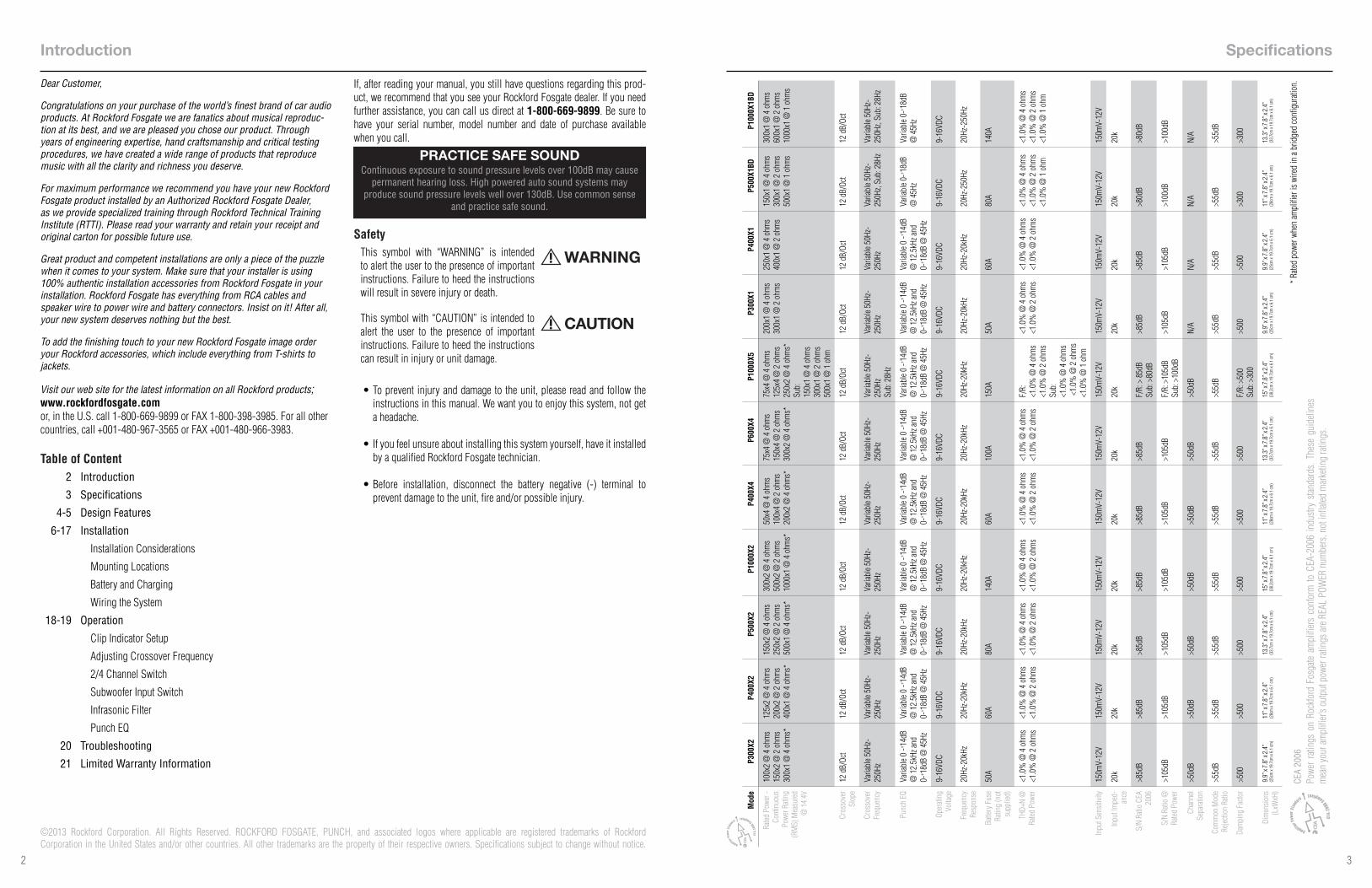
Specifications
CEA
2006
Powe
r ra
tings
on
Rock
ford
Fos
gate
ampl
ifier
s co
nfor
m to
CEA
-200
6 in
dustr
y sta
ndar
ds. T
hese
gui
delin
es
mea
n yo
ur am
plifi
er’s
outp
ut p
ower
ratin
gs ar
e REA
L PO
WER
num
bers
, not
infla
ted m
arke
ting
ratin
gs.
Mod
eP3
00X2
P400
X2P5
00X2
P100
0X2
P400
X4P6
00X4
P100
0X5
P300
X1P4
00X1
P500
X1BD
P100
0X1B
D
Rated
Pow
er -
Cont
inuo
us
Powe
r Rati
ng
(RM
S) M
easu
red
@ 1
4.4V
100x
2 @
4 o
hms
150x
2 @
2 o
hms
300x
1 @
4 o
hms*
125x
2 @
4 o
hms
200x
2 @
2 o
hms
400x
1 @
4 o
hms*
150x
2 @
4 o
hms
250x
2 @
2 o
hms
500x
1 @
4 o
hms*
300x
2 @
4 o
hms
500x
2 @
2 o
hms
1000
x1 @
4 o
hms*
50x4
@ 4
ohm
s10
0x4
@ 2
ohm
s20
0x2
@ 4
ohm
s*
75x4
@ 4
ohm
s15
0x4
@ 2
ohm
s30
0x2
@ 4
ohm
s*
75x4
@ 4
ohm
s12
5x4
@ 2
ohm
s25
0x2
@ 4
ohm
s*Su
b:
150x
1 @
4 o
hms
300x
1 @
2 o
hms
500x
1 @
1 o
hm
200x
1 @
4 o
hms
300x
1 @
2 o
hms
250x
1 @
4 o
hms
400x
1 @
2 o
hms
150x
1 @
4 o
hms
300x
1 @
2 o
hms
500x
1 @
1 o
hms
300x
1 @
4 o
hms
600x
1 @
2 o
hms
1000
x1 @
1 o
hms
Cros
sove
r Sl
ope
12 d
B/Oc
t12
dB/
Oct
12 d
B/Oc
t12
dB/
Oct
12 d
B/Oc
t12
dB/
Oct
12 d
B/Oc
t12
dB/
Oct
12 d
B/Oc
t12
dB/
Oct
12 d
B/Oc
t
Cros
sove
r Fr
eque
ncy
Varia
ble 5
0Hz-
250H
zVa
riabl
e 50H
z-25
0Hz
Varia
ble 5
0Hz-
250H
zVa
riabl
e 50H
z-25
0Hz
Varia
ble 5
0Hz-
250H
zVa
riabl
e 50H
z-25
0Hz
Varia
ble 5
0Hz-
250H
zSu
b: 2
8Hz
Varia
ble 5
0Hz-
250H
zVa
riabl
e 50H
z-25
0Hz
Varia
ble 5
0Hz-
250H
z, Su
b: 2
8Hz
Varia
ble 5
0Hz-
250H
z, Su
b: 2
8Hz
Punc
h EQ
Varia
ble 0
-+ 14dB
@
12.
5kHz
and
0-+ 18
dB @
45H
z
Varia
ble 0
-+ 14dB
@
12.
5kHz
and
0-+ 18
dB @
45H
z
Varia
ble 0
-+ 14dB
@
12.
5kHz
and
0-+ 18
dB @
45H
z
Varia
ble 0
-+ 14dB
@
12.
5kHz
and
0-+ 18
dB @
45H
z
Varia
ble 0
-+ 14dB
@
12.
5kHz
and
0-+ 18
dB @
45H
z
Varia
ble 0
-+ 14dB
@
12.
5kHz
and
0-+ 18
dB @
45H
z
Varia
ble 0
-+ 14dB
@
12.
5kHz
and
0-+ 18
dB @
45H
z
Varia
ble 0
-+ 14dB
@
12.
5kHz
and
0-+ 18
dB @
45H
z
Varia
ble 0
-+ 14dB
@
12.
5kHz
and
0-+ 18
dB @
45H
z
Varia
ble 0
-+ 18dB
@
45H
zVa
riabl
e 0-+ 18
dB
@ 4
5Hz
Oper
ating
Vo
ltage
9-16
VDC
9-16
VDC
9-16
VDC
9-16
VDC
9-16
VDC
9-16
VDC
9-16
VDC
9-16
VDC
9-16
VDC
9-16
VDC
9-16
VDC
Freq
uenc
y Re
spon
se20
Hz-2
0kHz
20Hz
-20k
Hz20
Hz-2
0kHz
20Hz
-20k
Hz20
Hz-2
0kHz
20Hz
-20k
Hz20
Hz-2
0kHz
20Hz
-20k
Hz20
Hz-2
0kHz
20Hz
-250
Hz20
Hz-2
50Hz
Batte
ry F
use
Ratin
g (n
ot
supp
lied)
50A
60A
80A
140A
60A
100A
150A
50A
60A
80A
140A
THD+
N @
Ra
ted P
ower
<1.0
% @
4 o
hms
<1.0
% @
2 o
hms
<1.0
% @
4 o
hms
<1.0
% @
2 o
hms
<1.0
% @
4 o
hms
<1.0
% @
2 o
hms
<1.0
% @
4 o
hms
<1.0
% @
2 o
hms
<1.0
% @
4 o
hms
<1.0
% @
2 o
hms
<1.0
% @
4 o
hms
<1.0
% @
2 o
hms
F/R:
<1
.0%
@ 4
ohm
s<1
.0%
@ 2
ohm
sSu
b:
<1.0
% @
4 o
hms
<1.
0% @
2 o
hms
<1.0
% @
1 o
hm
<1.0
% @
4 o
hms
<1.0
% @
2 o
hms
<1.0
% @
4 o
hms
<1.0
% @
2 o
hms
<1.0
% @
4 o
hms
<1.0
% @
2 o
hms
<1.0
% @
1 o
hm
<1.0
% @
4 o
hms
<1.0
% @
2 o
hms
<1.0
% @
1 o
hm
Inpu
t Sen
sitivi
ty15
0mV-
12V
150m
V-12
V15
0mV-
12V
150m
V-12
V15
0mV-
12V
150m
V-12
V15
0mV-
12V
150m
V-12
V15
0mV-
12V
150m
V-12
V15
0mV-
12V
Inpu
t Im
ped-
ance
20k
20k
20k
20k
20k
20k
20k
20k
20k
20k
20k
S/N
Ratio
CEA
20
06>8
5dB
>85d
B>8
5dB
>85d
B>8
5dB
>85d
BF/
R: >
85d
BSu
b: >
80dB
>85d
B>8
5dB
>80d
B>8
0dB
S/N
Ratio
@
Rated
Pow
er>1
05dB
>105
dB>1
05dB
>105
dB>1
05dB
>105
dBF/
R: >
105d
BSu
b: >
100d
B>1
05dB
>105
dB>1
00dB
>100
dB
Chan
nel
Sepa
ratio
n>5
0dB
>50d
B>5
0dB
>50d
B>5
0dB
>50d
B>5
0dB
N/A
N/A
N/A
N/A
Com
mon
Mod
e Re
jectio
n Ra
tio>5
5dB
>55d
B>5
5dB
>55d
B>5
5dB
>55d
B>5
5dB
>55d
B>5
5dB
>55d
B>5
5dB
Dam
ping
Fac
tor
>500
>500
>500
>500
>500
>500
F/R:
>50
0Su
b: >
300
>500
>500
>300
>300
Dim
ensio
ns
(LxW
xH)
9.9”
x 7.8”
x 2.4”
(25c
m x
19.7
cm x
6.1
cm)
11” x 7.
8” x 2.
4”(2
8cm
x 19
.7cm
x 6.
1 cm
)13
.3” x 7.
8” x 2.
4”(3
3.7c
m x
19.7
cm x
6.1
cm)
15” x 7.
8” x 2.
4”(3
8.2c
m x
19.7
cm x
6.1
cm)
11” x 7.
8” x 2.
4”(2
8cm
x 19
.7cm
x 6.
1 cm
)13
.3” x 7.
8” x 2.
4”(3
3.7c
m x
19.7
cm x
6.1
cm)
15” x 7.
8” x 2.
4”(3
8.2c
m x
19.7
cm x
6.1
cm)
9.9”
x 7.8”
x 2.4”
(25c
m x
19.7
cm x
6.1
cm)
9.9”
x 7.8”
x 2.4”
(25c
m x
19.7
cm x
6.1
cm)
11” x 7.
8” x 2.
4”(2
8cm
x 19
.7cm
x 6.
1 cm
)13
.3” x 7.
8” x 2.
4”(3
3.7c
m x
19.7
cm x
6.1
cm)
* Rate
d po
wer w
hen
ampl
ifier
is w
ired
in a
brid
ged
confi
gura
tion.

54
Design Features
Power/Protect LED Power LED illuminates blue when the unit is turned on. Protect LED illuminates yellow if a short circuit or to low of an impedance is detected at the speaker connections. Thermal LED illuminates red when amplifier overheats. The amplifier will automatically shut down if this occurs.
Output Clip Indicator ChartReference chart for the output clip in-dicator LED illumination color during input level setup.
Speaker TerminalsThe Speaker Terminals are nickel-plated captive c-clamp wire connectors (+ and -) will accommodate 8 AWG.
RCA Input/Pass-ThruThe RCA inputs are capable of accepting signal from either high-level(speaker) to low-level(RCA). When utilizing high-level for input signal the auto turn-on feature is active. The pass-thru RCA’s are passive, including full input signal range and auto turn-on functionality when active.
Subwoofer InputSetting this switch to the “On” position, utilizes the “Sub” inputs. (P1000X5)
Centering IndicatorsIndicators are located on the bottom side of the amplifier.
Output Clip IndicatorThe output clip indicator works in conjunction with the input level knob, illuminating to appropriate color depending on the audio content used for the setup.
Intput Clip IndicatorThe input clip indicator works in con-junction with the audio source volume knob, illuminating red when audio source reaches it’s clipping point.
Input Level KnobThe input level control is used to match the output of the audio source.
Design Features
Punch EQA Gyrator based Punch EQ that eliminates frequency shift with boost. This works along with the crossover switch on the amplifier.
Power/REM TerminalsThe power and ground will accommodate 4 AWG, while the remote will accommodate 12 AWG.(The REM terminal is used to remotely turn-on and turn-off the amplifier when +12V DC is applied.)
2/4 Channel SwitchSetting this switch to the 2CH. position, switches the inputs to a 2-channel mode, allowing connection to only the front inputs with a 4-channel output. (P400X4, P600X4, P1000X5)
Crossover SwitchSelectable switch for High-Pass (HP) or All Pass (AP) or Low-Pass (LP)
Variable CrossoverIs a built-in 12dB/octave Butterworth filter with a crossover point variable from 50Hz to 250Hz.
illus.-1.1
Remote Punch Level Control - In/OutRemotely control the output level of the amplifier. The PLC-OUT is used to daisy-chain additional amplifiers controlled by a single remote.
Infrasonic FilterA fixed 28Hz 12dB/octave filter designed to prevent frequencies below the audio range from being applied to the subwoofer from the amplifier. Consequently improving subwoofer performance and power han-dling, particularly in vented enclosures. (P500X1BD, P10001BD, P1000X5)
Remote Punch Level SwitchWhen activated, this allows the use of a optional re-mote Punch Level Controller. (P500X1BD, P10001BD, P1000X5)
INPUT CLIP REAR SUBFRONT
RIGHTLEFT
RIGHTLEFT
B+REM GND
REMOTEPUNCH LEVEL
PLC-OUTPLC-IN
FRONT REAR
RIGHTLEFTBRIDGED
RIGHTLEFTBRIDGED
SUB
BA
SPEAKERS
INPUT
2CH. - 4CH.

76
Contents
Installation ConsiderationsThe following is a list of tools needed for installation:
This section focuses on some of the vehicle considerations for install-ing your new amplifier. Pre-planning your system layout and best wiring routes will save installation time. When deciding on the layout of your new system, be sure that each component will be easily accessible for making adjustments.
If you feel unsure about installing this sys-tem yourself, have it installed by a qualified technician.
Before installation, disconnect the battery neg-ative (-) terminal to prevent damage to the unit, fire and/or possible injury.
Before beginning any installation, follow these simple rules:
1. Be sure to carefully read and understand the instructions before attempting to install the unit.
2. For safety, disconnect the negative lead from the battery prior to beginning the installation.
3. For easier assembly, we suggest you run all wires prior to mounting your unit in place.
4. Route all of the RCA cables close together and away from any high current wires.
5. Use high quality connectors for a reliable installation and to minimize signal or power loss.
•Fuse-holder and fuse. (See specifications for fuse rating)
•Volt/Ohm Meter
•Wire strippers
•Wire crimpers
•Wire cutters
•#2 Phillips screwdriver
•Battery post wrench
•Hand held drill w/assorted bits
•Assorted connectors
•Adequate Length—Red Power Wire
•Adequate Length—Remote Turn-on Wire
•Adequate Length—Black Grounding Wire
6. Think before you drill! Be careful not to cut or drill into gas tanks, fuel lines, brake or hydraulic lines, vacuum lines or electrical wiring when working on any vehicle.
7. Never run wires underneath the vehicle. Running the wires inside the vehicle provides the best protection.
8. Avoid running wires over or through sharp edges. Use rubber or plastic grommets to protect any wires routed through metal, especially the firewall.
9. ALWAYS protect the battery and electrical system from damage with proper fusing. Install the appropriate fuse holder and fuse on the +12V power wire within 18” (45.7 cm) of the battery terminal.
10. When grounding to the chassis of the vehicle, scrape all paint from the metal to ensure a good, clean ground connection. Grounding connections should be as short as possible and always be connected to metal that is welded to the main body, or chassis, of the vehicle. Seatbelt bolts should never be used for connecting to ground.
Mounting LocationsTo ensure optimal performance, mount the amplifier with at least 1” (2.54cm) of air gap around the amplifier’s heat sink to provide proper cooling.
Amplifier Centering Indicators
Centering indicators have been incorporated into the amplifier’s heatsink to aid in the installation process.
Trunk Mounting
Mounting the amplifier vertically or inverted will provide adequate cool-ing of the amplifier. Mounting the amplifier on the floor of the trunk will provide the best cooling of the amplifier.
Passenger Compartment Mounting
Mounting the amplifier in the passenger compartment will work as long as you provide a sufficient amount of air for the amplifier to cool itself. If you are going to mount the amplifier under the seat of the vehicle, you must have at least 1” (2.54cm) of air gap around the amplifier’s heat sink.
Never mount this unit in the engine compart-ment. Mounting the unit in the engine com-partment will void your warranty.
Battery and ChargingAmplifiers will put an increased load on the vehicle’s battery and charging system. We recommend checking your alternator and battery condition to ensure that the electrical system has enough capacity to handle the increased load of your stereo system. Stock electrical systems which are in good condition should be able to handle the extra load of any Prime Series amplifier without problems, although battery and alternator life can be reduced slightly. To maximize the performance of your amplifier, we suggest the use of a heavy duty battery and an energy storage capacitor.
Installation Installation
source unit’s remote amp on lead. If the source unit does not have this output available, the recommended solution is to wire a mechanical switch in line with a 12 volt source to activate the amplifier.
NOTE: When utilizing high-level for input signal the auto turn-on feature is active. With the auto turn-on active, the REM becomes an output to turn on/off up to two additional amplifiers or other accessories.
7. Securely mount the amplifier to the vehicle or amp rack. Be careful not to mount the amplifier on cardboard or plastic panels. Doing so may enable the screws to pull out from the panel due to road vibration or sudden vehicle stops.
8. Connect from source signal by plugging into the RCA input jacks at the amplifier. The input sensitivity ranges from 150mV-12V to accommodate signal from either high-level(speaker) to low-level(RCA).
NOTE: All “ACTIVE” inputs must have RCA jacks connected. Switch in 2CH. position,“ACTIVE” - Front channel inputs only. Switch in 4CH. position,“ACTIVE” - All Front and Rear channel inputs. Switch in FRONT. position,“ACTIVE” - Front channel inputs only for sub output. Switch in SUB position,“ACTIVE” - Sub inputs for sub output. When connecting to the 5-Channel inputs, be sure to route front, rear and sub RCA cables tightly together.
Always ensure power is off or disconnected at the amplifier before connecting RCA cables. Failure to do so may cause damage to the am-plifier and/or connected components.
9. Connect the speakers. Strip the speaker wires 1/2” and insert into the speaker terminal and tighten the set screw to secure into place. Be sure to maintain proper speaker polarity. DO NOT chassis ground any of the speaker leads as unstable operation may result.
10. Perform a final check of the completed system wiring to ensure that all connections are accurate. Check all power and ground connections for frayed wires and loose connections which could cause problems. Install inline fuse near battery connection.
NOTE: Follow the diagrams for proper signal polarity.
This amplifier is not recommended for im-pedance loads below 2-Ohm stereo/4-Ohm bridged for the multi-channel amplifiers and 1-ohm for mono amplifiers.
Wiring the SystemIf you do not feel comfortable with wiring your new unit, please see your local Authorized Rockford Fosgate Dealer for installation.
Before installation, disconnect the battery neg-ative (-) terminal to prevent damage to the unit, fire and/or possible injury.
Avoid running power wires near the low level input cables, antenna, power leads, sensitive equipment or harnesses. The power wires car-ry substantial current and could induce noise into the audio system.
1. Plan the wire routing. Keep RCA cables close together but isolated from the amplifier’s power cables and any high power auto accessories, especially electric motors. This is done to prevent coupling the noise from radiated electrical fields into the audio signal. When feeding the wires through the firewall or any metal barrier, protect them with plastic or rubber grommets to prevent short circuits. Leave the wires long at this point to adjust for a precise fit at a later time.
2. Prepare the RED wire (power cable) for attachment to the amplifier by stripping 1/2” of insulation from the end of the wire. Insert the bared wire into the B+ terminal and tighten the set screw to secure the cable in place.
NOTE: The B+ cable MUST be fused 18” or less from the vehicle’s battery. Install the fuse holder under the hood and ensure connections are water tight.
3. Trim the RED wire (power cable) within 18” of the battery and splice in a inline fuse holder (not supplied). See Specifications for the rating of the fuse to be used. DO NOT install the fuse at this time.
4. Strip 1/2” from the battery end of the power cable and crimp an appropriate size ring terminal to the cable. Use the ring terminal to connect to the battery positive terminal.
5. Prepare the BLACK wire (Ground cable) for attachment to the amplifier by stripping 1/2” of insulation from the end of the wire. Insert the bare wire into the GROUND terminal and tighten the set screw to secure the cable in place. Prepare the chassis ground by scraping any paint from the metal surface and thoroughly clean the area of all dirt and grease. Strip the other end of the wire and attach a ring connector. Fasten the cable to the chassis using a non-anodized screw and a star washer.
NOTE: Keep the length of the BLACK wire (Ground) as short as possible. Always less than 30”.
6. Prepare the Remote turn-on wire for attachment to the amplifier by stripping 1/2” of insulation from the end of the wire. Insert the bared wire into the REMOTE terminal and tighten the set screw to secure the wire in place. Connect the other end of the Remote wire to a switched 12 volt positive source. The switched voltage is usually taken from the
•Punch Amplifier
•Mounting Hardware
•Allen Wrench
•Quick Setup Guide
• Installation & Operation Manual
•Operation CD- (Test Tones & Installation Manual)

98
2-Channel (Stereo)P300X2, P400X2, P500X2, P1000X2
illus.-2.1
Installation Installation
2-Channel (Mono)P300X2, P400X2, P500X2, P1000X2
illus.-2.2
PASS-THRUConnect to inputsof 2nd amplifier*Installation option for multi-amp install
RIGHTLEFT
PASS-THRU
PLC-
OUT
INPUT
PLC-
IN
INPUT
REMOTEPUNCH LEVEL
INPUT CLIP
B+REM GND
RIGHTLEFTBRIDGED
SPEAKERS
PASS-THRUConnect to inputsof 2nd amplifier*Installation option for multi-amp install
RIGHTLEFT
PASS-THRU
PLC-
OUT
INPUT
PLC-
IN
INPUT
REMOTEPUNCH LEVEL
INPUT CLIP
B+REM GND
RIGHTLEFTBRIDGED
SPEAKERS
Optional Input Accessory
Left (+) Left (–) Right (+)Right (–)
Optional Input Accessory
Left (+) Left (–) Right (+)Right (–)

1110
4-Channel (Stereo)P400X4, P600X4
illus.-2.3 illus.-2.4
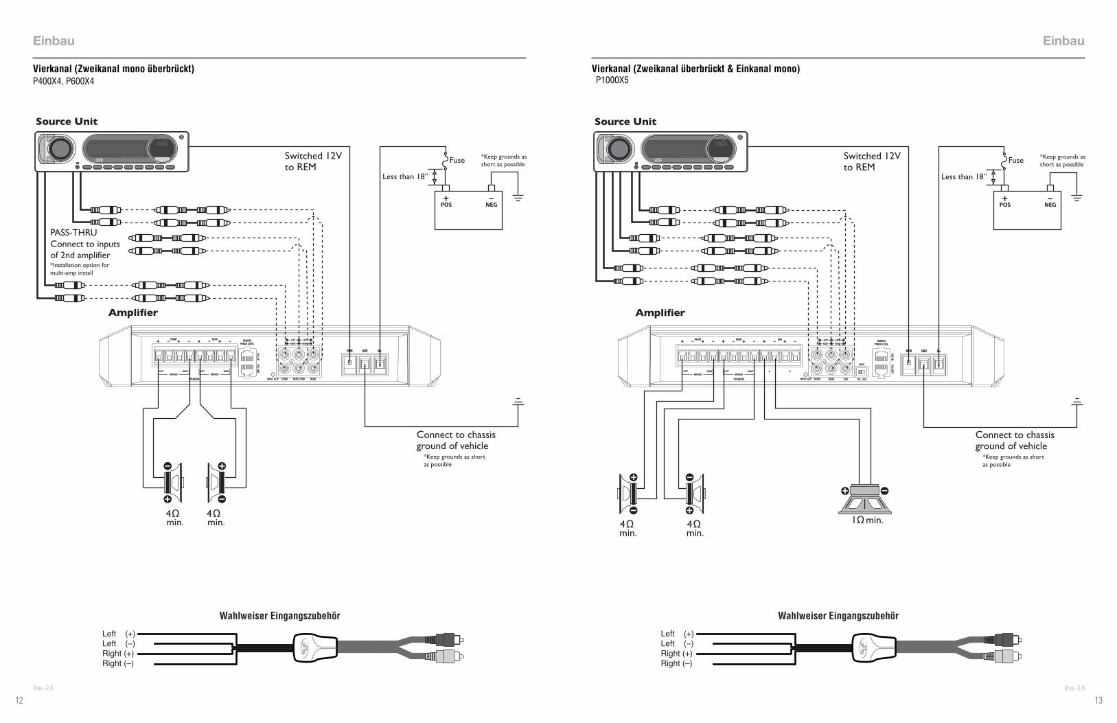
4-Channel (2ch Stereo & 1ch Mono-Bridged)P400X4, P600X4
Installation Installation
PASS-THRUConnect to inputsof 2nd amplifier*Installation option for multi-amp install
RIGHTLEFT
FRONT REAR
BRIDGEDRIGHTLEFT
BRIDGED
SPEAKERS
REMOTEPUNCH LEVEL
INPUT CLIP PASS-THRU REARFRONT
RIGHTLEFT
RIGHTLEFT
B+REM GND
PLC-OUTPLC-IN
PASS-THRUConnect to inputsof 2nd amplifier*Installation option for multi-amp install
RIGHTLEFT
FRONT REAR
BRIDGEDRIGHTLEFT
BRIDGED
SPEAKERS
REMOTEPUNCH LEVEL
INPUT CLIP PASS-THRU REARFRONT
RIGHTLEFT
RIGHTLEFT
B+REM GND
PLC-OUTPLC-IN
Optional Input Accessory
Left (+) Left (–) Right (+)Right (–)
Optional Input Accessory
Left (+) Left (–) Right (+)Right (–)

1312
4-Channel (2ch Mono-Bridged)P400X4, P600X4
illus.-2.5
3-Channel (2ch bridged & 1ch Mono)P1000X5
illus.-2.6
Installation Installation
PASS-THRUConnect to inputsof 2nd amplifier*Installation option for multi-amp install
RIGHTLEFT
FRONT REAR
BRIDGEDRIGHTLEFT
BRIDGED
SPEAKERS
REMOTEPUNCH LEVEL
INPUT CLIP PASS-THRU REARFRONT
RIGHTLEFT
RIGHTLEFT
B+REM GND
PLC-OUTPLC-IN
INPUT CLIP REAR SUBFRONT
RIGHTLEFT
RIGHTLEFT
B+REM GND
REMOTEPUNCH LEVEL
PLC-OUTPLC-IN
FRONT REAR
RIGHTLEFTBRIDGED
RIGHTLEFTBRIDGED
SUB
BA
SPEAKERS
INPUT
2CH. - 4CH.
Optional Input Accessory
Left (+) Left (–) Right (+)Right (–)
Optional Input Accessory
Left (+) Left (–) Right (+)Right (–)

1514
5-Channel (4ch Stereo & 1ch Mono)P1000X5
illus.-2.7
Installation
Parallel Wiring (Full Range Capable)P300X1, P400X1
illus.-2.8
Installation
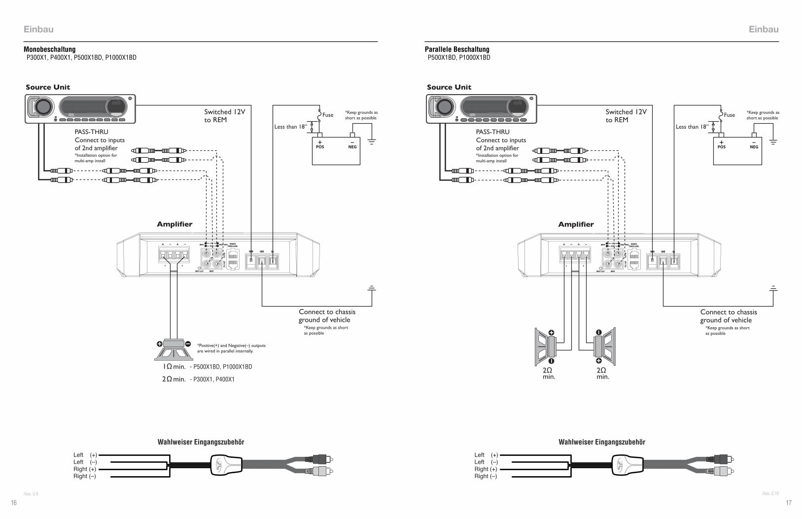
*Positive(+) and Negative(–) outputs are wired in parallel internally.
INPUT CLIP REAR SUBFRONT
RIGHTLEFT
RIGHTLEFT
B+REM GND
REMOTEPUNCH LEVEL
PLC-OUTPLC-IN
FRONT REAR
RIGHTLEFTBRIDGED
RIGHTLEFTBRIDGED
SUB
BA
SPEAKERS
INPUT
2CH. - 4CH.
PASS-THRUConnect to inputsof 2nd amplifier*Installation option for multi-amp install
RIGHTLEFT
PASS-THRU
PLC-
OUT
INPUT
PLC-
IN
INPUT
REMOTEPUNCH LEVEL
SPEAKERS INPUT CLIP
B+REM GND
BA
Optional Input Accessory
Left (+) Left (–) Right (+)Right (–)
Optional Input Accessory
Left (+) Left (–) Right (+)Right (–)

1716
Mono WiringP300X1, P400X1, P500X1BD, P1000X1BD
illus.-2.9
Installation
illus.-2.10
Installation
Parallel WiringP500X1BD, P1000X1BD
PASS-THRUConnect to inputsof 2nd amplifier*Installation option for multi-amp install
*Positive(+) and Negative(–) outputs are wired in parallel internally.
- P300X1, P400X1
- P500X1BD, P1000X1BD
RIGHTLEFT
PASS-THRU
PLC-
OUT
INPUT
PLC-
IN
INPUT
REMOTEPUNCH LEVEL
SPEAKERS INPUT CLIP
B+REM GND
BA
PASS-THRUConnect to inputsof 2nd amplifier*Installation option for multi-amp install
RIGHTLEFT
PASS-THRU
PLC-
OUT
INPUT
PLC-
IN
INPUT
REMOTEPUNCH LEVEL
SPEAKERS INPUT CLIP
B+REM GND
BA
Optional Input Accessory
Left (+) Left (–) Right (+)Right (–)
Optional Input Accessory
Left (+) Left (–) Right (+)Right (–)

1918
signal the auto turn-on feature is active. With the auto turn-on active, the REM becomes an output to turn on/off up to two additional amplifiers or other accessories.
Pass Thru The pass-thru RCA’s are passive, including full input signal range and auto turn-on functionality when active. When utilizing Pass Thru jacks, up to two additional amplifiers can be connected together.
Infrasonic Filter
The 28Hz 12dB/octave infrasonic filter limits the amount of low frequency information going to the woofer.
NOTE: We recommend using the infrasonic filter when using vented en-closures with this amplifier.
Punch EQThis works along with the crossover switch on the amplifier. When set to Low-Pass (LP) operation, this is a variable Bass Boost. When set to High-Pass (HP) operation, this is a variable Mid-Bass and Treble Boost. When set to All-Pass (AP) operation, both the Bass and Treble frequencies are boosted. Set this to your personal preference while listening to the system.
Over excursion and subsequent damage may occur at high levels of boost.
Remote Punch Level Control (Option)NOTE: Previous (prior to 2013) PEQ, Punch Bass and Para-Punch remotes will not work with these amplifiers.
Quick Install:
1. Using the screws supplied, install the mounting clip.
2. Slip the remote onto the mounting clip until it snaps into place.
3. Route and connect the cable to the remote and amplifier.
Operation:
4. When connected, the “Level Control” is linked and allows you to remotely control the output level of the amplifier from the dash or center console.
NOTE: Use the instructions that came with the remote for a variety of mountings that fit your preference.
Adjusting Crossover FrequencyDo the following individually for each channel.
Placing the crossover switch in the HP position sets the amplifier to the High Pass mode, enabling frequencies above the cut-off point to pass, adjust-able between 50-250Hz.
Placing the crossover switch in the AP position sets the amplifier to the All Pass mode, preventing any crossover adjustment, allowing all frequencies to pass.
Placing the crossover switch in the LP position sets the amplifier to the Low Pass mode, enabling frequencies below the cut-off point to pass, adjustable between 50-250Hz.
Turn the crossover adjustment knob all the way down. With the system playing, turn the crossover adjustment knob up slowly until the desired crossover point is achieved.
2/4 Channel SwitchSetting this switch to the 2CH. position, switches the inputs to a 2-channel mode, allowing con-nection to only the front inputs with a 4-channel output.
Output controls function the same as if the amplifier was in 4-channel mode.
All “ACTIVE” inputs must have RCA jacks connected. Switch in 2CH. position,“ACTIVE” - Front channel inputs only. Switch in 4CH. position,“ACTIVE” - All Front and Rear channel inputs.
NOTE: When connecting to the 4-Channel inputs, be sure to route both front and rear RCA cables tightly together.
Subwoofer Input Switch (P1000X5)Setting this switch to the Off position, utilizes the front inputs, allowing connection to only the front inputs with a subwoofer output. Setting this switch to the On position uses sub input.
Output controls function the same as if the amplifier was in 5-channel mode.
All “ACTIVE” inputs must have RCA jacks connected. Switch in FRONT. position,“ACTIVE” - Front channel inputs only for sub output. Switch in SUB position,“ACTIVE” - Sub inputs for sub output.
NOTE: When connecting to the 5-Channel inputs, be sure to route front, rear and sub RCA cables tightly together.
High Level InputConnect from source signal by plugging into the RCA input jacks at the amplifier. The input sensitivity ranges from 150mV-12V to accommodate signal from high-level(speaker) input. When utilizing high-level for input
Input Clip Indicator Setup
Step 1. Be sure to disconnect all speakers from the amplifier.
Failure to comply may cause damage to con-nected components and/or amplifier.
Step 2. Turn on the source unit with volume set to zero.
Step 3. Adjust the Bass & Treble levels on the source unit to flat.
Step 4. Insert test tone or music CD to play for setup.
Note: Use the 40Hz @ 0dB tone (Track 5) for mono amplifier applications or the 1kHz @ 0dB tone (Track 7) for multi-channel amplifier applications. Be sure your x-over is switched to the appropriate filter setting.
Step 5. Increase the source unit volume until the Input Clip Indicator il-luminates red.
Note: Input Clip can be viewed remotely with optional PLC2.
Step 6. Decrease the source unit volume slightly until the light turns completely off. This establishes your maximum source unit vol-ume for adjusting the Output Clip Indicator.
Note: Some source units will not clip.
Output Clip Indicator Setup
Step 7. Be sure to disconnect Punch Level Control - PLC (if equipped) from the amplifier.
Step 8. Adjust the Input Level knob until the Output Clip Indicator illu-minates to the appropriate color. Repeat for all channel levels of input.
Step 9. Turn the source unit volume down.
Step 10. Reconnect all speakers and Punch Level Control - PLC (if equipped) to the amplifier. Be sure to maintain proper speaker polarity.
Operation Operation
illus.-3.1
illus.-3.2
illus.-3.3
illus.-3.4
illus.-3.5
illus.-3.6
illus.-4.1 illus.-4.2
illus.-3.9
illus.-3.8
illus.-3.7illus.-4.3
illus.-4.4
illus.-4.5
illus.-4.6
Volume
Volume
REMOTEPUNCH LEVEL
INPUT CLIP PASS-THRU REARFRONT
RIGHTLEFT
RIGHTLEFT
PLC-OUTPLC-IN
REMOTEPUNCH LEVEL
INPUT CLIP PASS-THRU REARFRONT
RIGHTLEFT
RIGHTLEFT
PLC-OUTPLC-IN
Volume
Volume

2120
TroubleshootingNOTE: If you are having problems after installation follow the Trouble-shooting procedures below.
Check Amplifier for proper connections. Verify that POWER light is on. If POWER light is on skip to Step 3, if not continue.
1. Check in-line fuse on battery positive cable. Replace if necessary.
2. Check fuse(s) on amplifier. Replace if necessary.
3. Verify that Ground connection is connected to clean metal on the vehicle’s chassis. Repair/replace if necessary.
4. Verify there is 9 to 14.4 Volts present at the positive battery and remote turn-on cable. Verify quality connections for both cables at amplifier, stereo, and battery/fuseholder. Repair/replace if necessary.
Protect light is on.
1. If the Protect light is on, this is a sign of a possible short in the speaker connections. Check for proper speaker connections and use a volt/ohm meter to check for possible shorts in the speaker wiring. Too low of a speaker impedance may also cause Protect to light.
Check Amplifier for audio output.
1. Verify good RCA input connections at stereo and amplifier. Check entire length of cables for kinks, splices, etc. Test RCA inputs for AC volts with stereo on. Repair/replace if necessary.
2. Disconnect RCA input from amplifier. Connect RCA input from test stereo directly to amplifier input.
Check Amplifier if you experience Turn-on Pop.
1. Disconnect input signal to amplifier and turn amplifier on and off.
2. If the noise is eliminated, connect the REMOTE lead of amplifier to source unit with a delay turn-on module.
OR
1. Use a different 12 Volt source for REMOTE lead of amplifier.
Troubleshooting
Check Amplifier if you experience excess Engine Noise.
1. Route all signal carrying wires (RCA, Speaker cables) away from power and ground wires.
OR
1. Bypass any and all electrical components between the stereo and the amplifier(s). Connect stereo directly to input of amplifier. If noise goes away the unit being bypassed is the cause of the noise.
OR
1. Remove existing ground wires for all electrical components. Reground wires to different locations. Verify that grounding location is clean, shiny metal free of paint, rust etc.
OR
1. Add secondary ground cable from negative battery terminal to the chassis metal or engine block of vehicle.
OR
1. Have alternator and battery load tested by your mechanic. Verify good working order of vehicle electrical system including distributor, spark plugs, spark plug wires, voltage regulator etc.
Remote not functioning.
1. BD amplifiers remote switch in “ON” position.
OR
2. Remote plugged into remote PLC “IN” port
Remote Lights not functioning.
1. Remote plugged into remote PLC “IN” port
Rockford Corporation offers a limited warranty on Rockford Fosgate products on the following terms:Length of Warranty
Speakers, Signal Processors, PRIME and PUNCH Amplifiers – 1 Year POWER Amplifiers – 2 Years Any Factory Refurbished Product – 90 days (receipt required)
What is CoveredThis warranty applies only to Rockford Fosgate products sold to consumers by Authorized Rockford Fosgate Dealers in the United States of America or its possessions. Product purchased by consumers from an Authorized Rockford Fosgate Dealer in another country are covered only by that country’s Distribu-tor and not by Rockford Corporation.
Who is CoveredThis warranty covers only the original purchaser of Rockford product purchased from an Authorized Rockford Fosgate Dealer in the United States. In order to receive service, the purchaser must provide Rockford with a copy of the receipt stating the customer name, dealer name, product purchased and date of purchase.
Products found to be defective during the warranty period will be repaired or replaced (with a product deemed to be equivalent) at Rockford’s discretion.
What is Not Covered1. Damage caused by accident, abuse, improper operations,water, theft, shipping.2. Any cost or expense related to the removal or reinstallation of product.3. Service performed by anyone other than Rockford or an Authorized Rockford Fosgate Service Center.4. Any product which has had the serial number defaced, altered, or removed.5. Subsequent damage to other components.6. Any product purchased outside the U.S.7. Any product not purchased from an Authorized Rockford Fosgate Dealer.
Limit on Implied WarrantiesAny implied warranties including warranties of fitness for use and merchantability are limited in duration to the period of the express warranty set forth above. Some states do not allow limitations on the length of an implied warranty, so this limitation may not apply. No person is authorized to assume for Rockford Fosgate any other liability in connection with the sale of the product.
How to Obtain ServiceContact the Authorized Rockford Fosgate Dealer you purchased this product from. If you need further assistance, call 1-800-669-9899 for Rockford Cus-tomer Service. You must obtain an RA# (Return Authorization number) to return any product to Rockford Fosgate. You are responsible for shipment of product to Rockford.
EU WarrantyThis product meets the current EU warranty requirements, see your Authorized dealer for details.
Warranty

Einbau und Bedienung
VERSTÄRKER
P300X1 P300X2 P400X1
P400X2 P400X4 P500X1BD
P500X2 P600X4 P1000X1BD
P1000X2 P1000X5

32
Liebe Kundin, lieber Kunde,
wir gratulieren Ihnen zu Ihrem Kauf der weltweit besten Marke von Au-dioprodukten für Kraftfahrzeuge. Wir bei Rockford Fosgate sind Fanatiker, wenn es um die beste musikalische Reproduktion geht, und freuen uns darüber, dass Sie unser Produkt gewählt haben. Durch jahrelange Ing-enieurserfahrung, Handwerkstechnik und kritische Testverfahren haben wir ein breites Spektrum an Produkten geschaffen, die die Musik mit aller Klarheit und Klangschönheit reproduzieren, die Sie verdienen.
Zur maximalen Performance empfehlen wir, dass Sie Ihr neues Rock-ford Fosgate-Produkt von einem Vertragshändler von Rockford Fosgate einbauen lassen, da wir durch das Rockford Technical Training Institute (RTTI) spezialisierte Ausbildung bieten. Bitte lesen Sie Ihre Garantie und bewahren Sie Ihre Quittung und Originalverpackung zum eventuellen späteren Gebrauch auf.
Hervorragende Produkte und kompetenter Einbau sind nur Teile des Puzzles, wenn es um Ihr System geht. Vergewissern Sie sich, dass der-jenige, der Ihr System einbaut, bei Ihrem Einbau ausschließlich authen-tischen Installationszubehör von Rockford Fosgate verwendet. Rockford Fosgate führt alles von RCA- und Lautsprecherkabeln zu Stromkabeln und Batterieadaptern. Bestehen Sie darauf! Schließlich verdient Ihr neues System nur das Beste.
Um Ihrem neuen Rockford Fosgate-Image den letzten Schliff zu ver-leihen, bestellen Sie Ihre Rockford-Accessoires. Dazu gehört alles von T-Shirts zu Jacken.
Die neusten Informationen zu allen Rockford-Produkten finden Sie auf unserer Website: www.rockfordfosgate.com
oder in den USA telefonisch unter 1-800-669-9899 oder per Fax unter 1-800-398-3985. In allen anderen Ländern gelten die Rufnummer +001-480-967-3565 bzw. Faxnummer +001-480-966-3983.
SicherheitshinweiseDieses Symbol mit dem Wort „WARNING“ (WARNUNG) soll den Benutzer auf wichtige Hinweise aufmerksam machen. Nichtbeach-tung der Hinweise führt zu schweren Verletzungen oder Tod.
Dieses Symbol mit dem Wort „CAUTION“ (VORSICHT) soll den Benutzer auf wichtige Hinweise aufmerksam machen. Nichtbeach-tung der Hinweise kann zu Verletzungen oder zu Schäden am Gerät führen.
•Bitte lesen Sie zur Vermeidung von Verletzungen und Schäden am Gerät die Hinweise in dieser Anleitung. Wir möchten, dass Ihnen dieses System Freude, nicht Kopfschmerzen bereitet.
•Wenn Sie beim Einbau des Geräts unsicher sind, lassen Sie es bitte von einem qualifizierten Rockford Fosgate-Techniker.
•Entfernen Sie vor dem Einbau den negativen (-) Batteriepol, um Schäden am Gerät, Feuer bzw. mögliche Verletzungen zu vermeiden.
Falls Sie nach Lesen der Bedienungsanleitung noch Fragen hinsichtlich dieses Produkts haben, empfehlen wir, dass Sie einen Rockford Fosgate-Fachhändler kontaktieren. Wenn Sie weitere Fragen haben, können Sie uns direkt unter +001-480-967-3565 anrufen. Bei Ihrem Anruf haben Sie bitte Ihre Seriennummer, Modellnummer und das Kaufdatum griffbereit.
Inhaltsverzeichnis
Einleitung
©2013 Rockford Corporation. Alle Rechte vorbehalten. ROCKFORD FOSGATE, PUNCH und diesbezügliche Logos sind, falls zutreffend, eingetragene Markenzeichen von Rockford Corpo-ration in den Vereinigten Staaten und/oder anderen Ländern. Alle anderen Marken sind das Eigentum ihrer jeweiligen Inhaber. Technische Daten können sich ohne Vorankündigung ändern.
PRAKTIZIEREN SIE SICHEREN SOUNDFortgesetzte Geräuschdruckpegel von über 100 dB können beim Menschen zu permanentem Hörverlust führen. Leistungsstarke
Autosoundsysteme können Geräuschdruckpegel erzeugen, die weit über 130 dB liegen. Bitten wenden Sie gesunden Menschenverstand an und
praktizieren Sie sicheren Sound.
2 Einleitung
3 Technische Daten
4-5 Gerätefunktionen
6-17 Einbau
Einbauüberlegungen
Befestigungsstellen
Batterie und Aufladen
Verkabelung des Systems
18-19 Bedienung
Einstellung der Begrenzungsanzeige
Einstellung der Crossover-Frequenz
Zwei-/Vierkanal-Schalter
Subwoofer-Eingangsschalter
Infraschallfilter
Punch-EQ
20 Fehlerbeseitigung
Technische Daten
CEA
2006
Die
Nenn
leistu
ngen
der
Roc
kford
Fos
gate-
Vers
tärke
r geh
en m
it de
n CE
A-20
06-In
dustr
ienor
men
kon
form
. Dies
e Ri
chtli
nien
bed
euten
, das
s di
e Au
sgan
gsne
nnlei
stung
en Ih
res V
erstä
rker
s ECH
TE L
EIST
UNGS
ZAHL
EN si
nd, n
icht ü
berh
öhte
Mar
ketin
gzah
len
Mod
ell
P300
X2P4
00X2
P500
X2P1
000X
2P4
00X4
P600
X4P1
000X
5P3
00X1
P400
X1P5
00X1
BDP1
000X
1BD
Nenn
leistu
ng -
Effek
tiv-le
istun
g (R
MS)
bei
14,4
V
gem
esse
n
100
x 2 an
4 Ω
150
x 2 an
2 Ω
300
x 1 an
4 Ω
*
125
x 2 an
4 Ω
200
x 2 an
2 Ω
400
x 1 an
4 Ω
150
x 2 an
4 Ω
250
x 2 an
2 Ω
500
x 1 an
4 Ω
*
300
x 2 an
4 Ω
500
x 2 an
2 Ω
1000
x 1
an 4
Ω*
50 x
4 an
4 Ω
100
x 4 an
2 Ω
200
x 2 an
4 Ω
*
75 x
4 an
4 Ω
150
x 4 an
2 Ω
300
x 2 an
4 Ω
*
75 x
4 an
4 Ω
125
x 4 an
2 Ω
250
x 2 an
4 Ω
*Su
b:
150
x 1 an
4 Ω
300
x 1 an
2 Ω
500
x 1 an
1 Ω
200
x 1 an
4 Ω
300
x 1 an
2 Ω
250
x 1 an
4 Ω
400
x 1 an
2 Ω
150
x 1 an
4 Ω
300
x 1 an
2 Ω
500
x 1 an
1 Ω
tt
300
x 1 an
4 Ω
600
x 1 an
2 Ω
1000
x 1
an 1
Ω
Flan
kens
teilh
eit12
dB/
Oktav
e12
dB/
Oktav
e12
dB/
Oktav
e12
dB/
Oktav
e12
dB/
Oktav
e12
dB/
Oktav
e12
dB/
Oktav
e12
dB/
Oktav
e12
dB/
Oktav
e12
dB/
Oktav
e12
dB/
Oktav
e
Über
gang
s-Fr
eque
nzVa
riabe
l 50
Hz -
250
HzVa
riabe
l 50
Hz -
250
HzVa
riabe
l 50
Hz -
250
HzVa
riabe
l 50
Hz -
250
HzVa
riabe
l 50
Hz -
250
HzVa
riabe
l 50
Hz -
250
HzVa
riabe
l 50
Hz -
250
HzSu
b: 2
8Hz
Varia
bel 5
0 Hz
- 25
0 Hz
Varia
bel 5
0 Hz
- 25
0 Hz
Varia
bel 5
0 Hz
- 25
0 Hz
, Sub
: 28H
zVa
riabe
l 50
Hz -
250
Hz, S
ub: 2
8Hz
Punc
h-EQ
Varia
bel 0
- +1
4 dB
bei
12,5
kHz
und
0 - +
18 d
B be
i 45
Hz
Varia
bel 0
- +1
4 dB
bei
12,5
kHz
und
0 - +
18 d
B be
i 45
Hz
Varia
bel 0
- +1
4 dB
bei
12,5
kHz
und
0 - +
18 d
B be
i 45
Hz
Varia
bel 0
- +1
4 dB
be
i 12,
5 kH
z und
0 -
+18
dB b
ei 45
Hz
VVar
iabel
0 - +
14
dB b
ei 12
,5 kH
z un
d 0
- +18
dB
bei
45 H
z
Varia
bel 0
- +1
4 dB
bei
12,5
kHz
und
0 - +
18 d
B be
i 45
Hz
Varia
bel 0
- +1
4 dB
bei
12,5
kHz
und
0 - +
18 d
B be
i 45
Hz
Varia
bel 0
- +1
4 dB
bei
12,5
kHz
und
0 - +
18 d
B be
i 45
Hz
Varia
bel 0
- +1
4 dB
bei
12,5
kHz
und
0 - +
18 d
B be
i 45
Hz
Varia
bel 0
- +1
8 dB
be
i 45
HzVa
riabe
l 0 -
+18
dB
bei 4
5 Hz
Betri
ebs-
span
nung
9-16
VDC
9-16
VDC
9-16
VDC
9-16
VDC
9-16
VDC
9-16
VDC
9-16
VDC
9-16
VDC
9-16
VDC
9-16
VDC
9-16
VDC
Freq
uenz
-gan
g20
Hz-2
0kHz
20Hz
-20k
Hz20
Hz-2
0kHz
20Hz
-20k
Hz20
Hz-2
0kHz
20Hz
-20k
Hz20
Hz-2
0kHz
20Hz
-20k
Hz20
Hz-2
0kHz
20Hz
-250
Hz20
Hz-2
50Hz
Empf
ohlen
er
Sich
erun
gswe
rt (n
icht i
m
Liefe
rum
fang)
50A
60A
80A
140A
60A
100A
150A
50A
60A
80A
140A
THD+
N be
i Ne
nn-le
istun
g<1
,0 %
an 4
Ω<1
,0 %
an 2
Ω<1
,0 %
an 4
Ω<1
,0 %
an 2
Ω<1
,0 %
an 4
Ω<1
,0 %
an 2
Ω<1
,0 %
an 4
Ω<1
,0 %
an 2
Ω<1
,0 %
an 4
Ω<1
,0 %
an 2
Ω<1
,0 %
an 4
Ω<1
,0 %
an 2
ΩF/
R:
<1,0
% an
4 Ω
<1,0
% an
2 Ω
Sub:
<1
,0 %
an 4
Ω<1
,0 %
an 2
Ω<1
,0 %
an 1
Ω
<1,0
% an
4 Ω
<1,0
% an
2 Ω
<1,0
% an
4 Ω
<1,0
% an
2 Ω
<1,0
% an
4 Ω
<1,0
% an
2 Ω
<1,0
% an
1 Ω
<1,0
% an
4 Ω
<1,0
% an
2 Ω
<1,0
% an
1 Ω
Eing
angs
-em
p-fin
dlich
-keit
150m
V-12
V15
0mV-
12V
150m
V-12
V15
0mV-
12V
150m
V-12
V15
0mV-
12V
150m
V-12
V15
0mV-
12V
150m
V-12
V15
0mV-
12V
150m
V-12
V
Eing
angs
-im
pend
anz
20.0
00 Ω
20.0
00 Ω
20.0
00 Ω
20.0
00 Ω
20.0
00 Ω
20.0
00 Ω
20.0
00 Ω
20.0
00 Ω
20.0
00 Ω
20.0
00 Ω
20.0
00 Ω
Sign
al-Ra
usch
-Ab
stund
CE
A 20
06
>85d
B>8
5dB
>85d
B>8
5dB
>85d
B>8
5dB
F/R:
> 8
5dB
Sub:
>80
dB>8
5dB
>85d
B>8
0dB
>80d
B
Sign
al-Ra
usch
-Ab
stund
bei
Nenn
-leist
ung
>105
dB>1
05dB
>105
dB>1
05dB
>105
dB>1
05dB
F/R:
>10
5dB
Sub:
>10
0dB
>105
dB>1
05dB
>100
dB>1
00dB
Kana
l-tre
nnun
g>5
0dB
>50d
B>5
0dB
>50d
B>5
0dB
>50d
B>5
0dB
nich
t vor
hand
en
nich
t vor
hand
en
nich
t vor
hand
en
nich
t vor
hand
en
Gleic
htak
t-un
terdr
ü-ck
ung
>55d
B>5
5dB
>55d
B>5
5dB
>55d
B>5
5dB
>55d
B>5
5dB
>55d
B>5
5dB
>55d
B
Däm
pfun
gs-
fakto
r>5
00>5
00>5
00>5
00>5
00>5
00F/
R: >
500
Sub:
>30
0>5
00>5
00>3
00>3
00
Abm
essu
ngen
(L
xWxH
)25
cm x
19.7
cm x
6.1
cm28
cm x
19.7
cm x
6.1
cm33
.7cm
x 19
.7cm
x 6.
1 cm
38.2
cm x
19.7
cm x
6.1
cm28
cm x
19.7
cm x
6.1
cm33
.7cm
x 19
.7cm
x 6.
1 cm
38.2
cm x
19.7
cm x
6.1
cm25
cm x
19.7
cm x
6.1
cm25
cm x
19.7
cm x
6.1
cm28
cm x
19.7
cm x
6.1
cm33
.7cm
x 19
.7cm
x 6.
1 cm
* Ne
nnlei
stung
, wen
n sic
h de
r Ver
stärk
er in
der
übe
r-br
ückte
n Ko
nfigu
rieru
ng b
efind
et

54
Gerätefunktionen
Betriebs-/Schutz-LEDDie Betriebs-LED leuchtet blau, wenn das Gerät eingeschaltet ist. Die Schutz-LED leuchtet gelb, wenn ein Kurzschluss oder zu niedrige Impen-danz an den Lautsprecheranschlüssen entdeckt wird. Die Thermal-LED leuchtet rot, wenn der Verstärker heißläuft. Wenn dies eintritt, schaltet sich der Verstärker automatisch ab.
Tabelle zur Ausgangsbegrenzungsanzeige
Bezugstabelle für die Farben, in denen die Ausgangsbegrenzungsanzeige während der Pegeleinstellung aufleuchtet.
LautsprecheranschlüsseDie Lautsprecheranschlüsse sind ver-nickelte C-Klemmen-Sicherheitsleitungs-verbinder (+ und -) und nehmen 8 AWG auf.
RCA-Eingang/-DurchgangDie RCA-Eingänge können Signale entweder von Hochpegel (Lautsprecher) bis Nied-rigpegel (RCA) annehmen. Bei Verwendung eines Hochpegels als Eingangssignals ist die Autoeinschaltfunktion aktiv. Die Durchgangs-RCA sind passiv einschließlich des vollen Eingangssignalsspektrums und der Autoeinschaltfunktionalität, wenn aktiv.
Subwoofer-EingangWird dieser Schalter in die „On“-Position gebracht, werden die „Sub“-Eingänge genutzt. (P1000X5)
BefestigungDie Befestigungslöcher zur Montage befinden sich auf der Unterseite des Verstärkers .
AusgangsbegrenzungsanzeigeDie Ausgangsbegrenzungsanzeige funktioniert in Verbindung mit dem Eingangspegelregler und leuchtet je nach dem zur Einstellung benutzten Au-dioinhalt in der entsprechenden Farbe auf.
EingangsbegrenzungsanzeigeDie Eingangsbegrenzungsanzeige funk-tioniert in Verbindung mit dem Audio-quellen-Lautstärkeregler und leuchtet rot auf, wenn die Audioquelle ihren Be-grenzungspunkt erreicht hat.
EingangspegelreglerDer Eingangspegelregler dient dazu, den Ausgang der Audioquelle anzugleichen.
Gerätefunktionen
Punch-EQEin Gyrator-basierter Punch-EQ, der Frequenzver-schiebung mit Boost eliminiert. Er funktioniert zusam-men mit dem Crossover-Schalter am Verstärker.
Strom-/FernsteuerungsanschlüsseDie Strom- und Masseanschlüsse nehmen 4 AWG auf, der Fernsteuerungsanschluss 12 AWG. (Der Fernsteuerunganschluss wird zur Fernein- und -ausschaltung des Verstärkers verwendet, wenn +12 VDC angelegt werden.)Zwei-/Vierkanal-Schalter
Einstellung dieses Schalters auf die Zweikanalposition schaltet die Eingänge in einen Zweikanalmodus und er-möglicht den Anschluss eines Vierkanalausgangs nur an die Fronteingänge. (P400X4, P600X4, P1000X5)
Crossover-SchalterWahlschalter für Hochpass (HP), Allpass (AP) oder Tiefpass (LP).
Variables CrossoverIst ein integrierter 12 dB/Oktav-Butterworth-Filter mit einem zwischen 50 und 250 Hz variablen Crossover-Punkt.
illus.-1.1
Fernsteuerung des Punch-Pegels (PLC) - Ein/Aus
Fernsteuert den Ausgangspegel des Verstärkers. Der PLC-Ausgang wird zur Verkettung zusätzlicher Verstärk-er benutzt, die mit einer einzigen Fernsteuerung bedient werden.
InfraschallfilterEin unveränderbarer 28 Hz 12 dB / Oktav-Filter, der dazu konzipiert ist, die Weitergabe von Frequenzen unterhalb des Tonfrequenzbereichs vom Verstärker an den Subwoofer zu verhindern. Consequently improv-ing subwoofer performance and power handling, par-ticularly in vented enclosures. (P500X1BD, P10001BD, P1000X5)
Fernsteuerung des Punch-Pegels (PLC) - Ein/Aus
Fernsteuert den Ausgangspegel des Verstärkers. Der PLC-Ausgang wird zur Verkettung zusätzlicher Ver-stärker benutzt, die mit einer einzigen Fernsteuerung bedient werden. (P500X1BD, P10001BD, P1000X5)
INPUT CLIP REAR SUBFRONT
RIGHTLEFT
RIGHTLEFT
B+REM GND
REMOTEPUNCH LEVEL
PLC-OUTPLC-IN
FRONT REAR
RIGHTLEFTBRIDGED
RIGHTLEFTBRIDGED
SUB
BA
SPEAKERS
INPUT
2CH. - 4CH.

76
Inhalt
EinbauüberlegungenDie folgenden Werkzeuge werden für den Einbau benötigt:
Dieser Abschnitt konzentriert sich auf bestimmte Überlegungen zum Ein-bau Ihres neuen Verstärkers im Fahrzeug. Vorausplanung Ihres System-layouts und der besten Verkabelungsrouten spart Zeit beim Einbau. Prüfen Sie bei der Wahl eines Layouts für Ihr neues System, ob alle Komponenten leicht erreichbar sind, um Einstellungen vorzunehmen.
Wenn Sie beim Einbau des Geräts unsicher sind, lassen Sie es von einem qualifizierten Techniker einbauen.
Entfernen Sie vor dem Einbau den negativen (-) Batteriepol, um Schäden am Gerät, Feuer bzw. mögliche Verletzungen zu vermeiden.
Befolgen Sie vor dem Einbau diese einfachen Regeln:
1. Lesen Sie die Anleitung sorgfältig, bevor Sie versuchen das Gerät einzubauen.
2. Entfernen Sie vor dem Einbau aus Sicherheitsgründen das negative Kabel von der Batterie.
3. Um die Montage zu erleichtern, empfehlen wir alle Kabel vor der Befestigung Ihres Geräts zu verlegen.
4. Verlegen Sie alle RCA-Kabel dicht zusammen und im Abstand zu jeglichen Hochstromkabeln.
5. Verwenden Sie nur Qualitätsstecker, um einen zuverlässigen Einbau zu gewährleisten und Signal- und Stromverlust zu minimieren.
6. Denken Sie nach, bevor Sie bohren! Achten Sie darauf, nicht in den Benzintank, die Benzin-, Brems- oder hydraulischen Leitungen, Vakuumleitungen oder Elektrokabel zu schneiden oder zu bohren, wenn Sie am Fahrzeug arbeiten.
•Sicherungsfassung und Sicherung (Siehe Technische Daten bezüglich des Bemessungsstroms der Sicherung)
•Spannungs- und Widerstandsmesser
•Abisolierzange•Drahtkripper•Drahtschere•Kreuzschraubenzieher Nr. 2
•Batteriestützenschlüssel•Handbohrer mit verschiedenen
Bohrerspitzen•Verschiedene Anschlussstecker•Angemessene Länge rotes
Stromkabel•Angemessene Länge
Ferneinschaltkabel•Angemessene Länge schwarzes
Massekabel
7. Verlegen Sie Kabel nie unter dem Fahrzeug. Die Kabel im Fahrzeug zu verlegen, bietet den besten Schutz.
8. Vermeiden Sie es, Kabel über scharfe Kanten zu verlegen. Verwenden Sie Gummi- oder Plastikringe, um Kabel zu schützen, die durch Metall verlegt werden (besonders die Feuerwand).
9. Schützen Sie die Batterie und das elektrische System IMMER durch ordnungsgemäße Sicherungen vor Schäden. Installieren Sie die entsprechende Sicherungsfassung und Sicherung auf dem +12 V Stromkabel maximal 45 cm vom Batteriepol.
10. Kratzen Sie bei der Erdung über das Fahrgestell alle Farbe vom Metall, um eine gute, saubere Masseverbindung zu gewährleisten. Masseverbindungen sollten so kurz wie möglich und stets an Metall angeschlossen sein, das an die Karosserie oder das Fahrgestell geschweißt ist. Die Bolzen der Sicherheitsgurte dürfen nicht zur Erdung benutzt werden.
BefestigungsstellenUm optimale Leistung zu gewährleisten, den Verstärker so einbauen, dass um die Wärmesenke herum zur ordnungsgemäßen Kühlung ein Luftspalt von wenigsten 2,5 cm verbleibt.
Zentrieranzeigen des Verstärkers
Zur Erleichterung des Einbauprozesses wurden Zentrieranzeigen in die Wärmesenke des Verstärkers integriert.
Befestigung im Kofferraum
Vertikale oder umgekehrte Befestigung des Verstärkers bietet angemes-sene Kühlung des Verstärkers. Befestigung des Verstärkers auf dem Boden des Kofferraums bietet die beste Kühlung des Verstärkers.
Befestigung im Fahrgastraum
Befestigung im Fahrgastraum ist möglich, solange ausreichende Luftzu-fuhr zur Kühlung des Verstärkers gewährleistet ist. Wenn Sie den Ver-stärker unter dem Sitz befestigen, muss ein Luftspalt von wenigstens 2,5 cm um die Wärmesenke des Verstärkers herum vorhanden sein.
Das Gerät darf nicht im Motorraum befestigt werden. Ein solcher Einbau führt zum Verlust der Garantie.
Batterie und AufladenVerstärker belasten die Fahrzeugbatterie und das Aufladungssystem zusätzlich. Wir empfehlen, dass Sie Ihre Lichtmaschine und den Batterie-zustand prüfen, damit das elektrische System über ausreichende Kapazität verfügt, um die zusätzliche Last Ihres Stereosystems zu bewältigen. Gän-gige Elektrosysteme, die sich in gutem Zustand befinden, sollten in der Lage sein, die zusätzliche Last eines Prime Series-Verstärkers problemlos zu bewältigen, jedoch kann sich die Lebenserwartung der Batterie und Li-chtmaschine geringfügig verringern. Um die Leistung Ihres Verstärkers zu maximieren, empfehlen wir die Benutzung einer leistungsstarken Batterie und eines Energiespeichers.
Einbau Einbau
anziehen, um den Draht zu befestigen. Das andere Ende des Fernsteuerungskabels an eine geschaltete +12 V-Stromquelle anschließen. Die geschaltete Spannung wird in der Regel von der Fernsteuerungsverstärker-Einschaltader des Source-Geräts geholt. Falls das Source-Gerät diese Art von Ausgang nicht hat, ist es angeraten, eine mechanische Schaltung inline mit einer 12 V-Quelle anzubringen, um den Verstärker einzuschalten.
HINWEIS: Bei Verwendung eines Hochpegels als Eingangssignals ist die Autoeinschaltfunktion aktiv. Wenn die Autoeinschaltung aktiv ist, wird die Fernsteuerung zu einem Ausgang, um bis zu zwei weitere Verstärker oder andere Peripheriegeräte ein- bzw. auszuschalten.
7. Den Verstärker gut am Fahrzeug oder am Verstärkergestell befestigen. Den Verstärker nicht versehentlich an Papp- oder Plastikpaneelen befestigen. Auf diese Weise könnten sich die Schrauben aufgrund von Straßenvibration oder durch plötzliches Bremsen aus dem Paneel lösen.
8. Die Verbindung zum Source-Signal durch Einstöpseln in die RCA-Eingangsbuchsen am Verstärker herstellen. Die RCA-Eingänge können Signale entweder von Hochpegel (Lautsprecher) bis Niedrigpegel (RCA) annehmen.
HINWEIS: Alle „ACTIVE“-Eingänge müssen an RCA-Buchsen angeschlos-sen sein. Schalter in der Zweikanalposition, „ACTIVE“ – nur Frontkanale-ingänge. Schalter in der Vierkanalposition, „ACTIVE“ – alle Front- und Rearkanaleingänge. Schalter in der FRONT-Position, „ACTIVE“ – Front-kanaleingänge nur für Sub-Ausgang. Schalter in der SUB-Position, „AC-TIVE“ – Sub-Eingänge für Sub-Ausgang. Beim Anschluss an die Fünfka-naleingänge darauf achten, dass die Front-, Rear- und Sub-RCA-Kabel dicht zusammen verlegt werden.
Stets gewährleisten, dass der Betriebsschal-ter ausgeschaltet oder das Stromkabel vom
Verstärker abgezogen ist, bevor RCA-Kabel ansgeschlossen werden. Ge-schieht dies nicht, können der Verstärker und/oder die angeschlossenen Komponenten beschädigt werden.
9. Die Lautsprecher anschließen. Die Lautsprecherdrähte auf 1 cm abisolieren und in den Lautsprecheranschluss einführen. Die Feststellschraube anziehen, um die Drähte zu befestigen. Dabei die Lautsprecherpolarität beachten. Die Lautsprecheradern NICHT über das Fahrgestell erden, da dies zu unstabilem Betrieb führen kann.
10. Überprüfen Sie die Verkabelung des kompletten Systems ein letztes Mal um zu gewährleisten, dass alle Anschlüsse korrekt sind. Überprüfen Sie alle Strom- und Masseanschlüsse auf beschädigte Drähte oder lose Anschlüsse, die Probleme verursachen könnten. Bringen Sie die Inline-Sicherung in der Nähe des Batterieanschlusses an.
HINWEIS: Beachten Sie zur ordnungsgemäßen Signalpolarität die Dia-gramme.
Dieser Verstärker wird nicht für Impedanzlas-ten unter 2 Ohm stereo oder 4 Ohm überbrückt
bei Multikanalverstärkern und 1 Ohm bei Monoverstärkern empfohlen.
Verkabelung des SystemsWenn Sie beim Verkabeln Ihres neuen Geräts un-sicher sind, lassen Sie es bitte von einem Rock-
ford Fosgate-Vertragshändler einbauen.
Entfernen Sie vor dem Einbau den negativen (-) Batteriepol, um Schäden am Gerät, Feuer bzw.
mögliche Verletzungen zu vermeiden.
Vermeiden Sie es, Stromkabel in der Nähe von Niedrigpegel-Eingangskabeln, der Antenne,
Stromadern, sensiblem Gerät oder Kabelbäumen zu verlegen. Die Stromk-abel führen eine erhebliche Menge an Strom und können Geräusche in das Audiosystem eintragen.
1. Die Kabelwege im Voraus planen. RCA-Kabel eng zusammen aber isoliert von den Stromkabeln des Verstärkers und anderem Hochstrom-Autozubehör – besonders elektrischen Motoren – verlegen. Dadurch wird die Einkopplung von Geräuschen aus dem elektrischen Strahlungsfeld in das Audiosignal vermieden. Bei der Verlegung von Kabeln durch die Feuerwand oder über andere Metallbarrieren zum Schutz Plastik- oder Gummiringe verwenden, um Kurzschlüsse zu vermeiden. Die Kabel zunächst etwas länger belassen, damit die präzise Länge später festgelegt werden kann.
2. Das ROTE Kabel (Stromkabel) durch Abisolieren von 1 cm am Ende des Kabels vorbereiten. Den blanken Draht in den „B+“-Anschluss einführen und die Einstellschraube anziehen, um das Kabel zu befestigen.
HINWEIS: Das B+-Kabel MUSS im Abstand von höchstens 45 cm von der Fahrzeugbatterie mit einer Sicherung versehen werden. Die Sicher-ungsfassung unter der Motorhaube anbringen und gewährleisten, dass die Anschlüsse wasserdicht sind.
3. Den ROTEN Draht (Stromkabel) höchstens 45 cm von der Batterie abisolieren und eine Inline-Sicherungsfassung (liegt nicht bei) einspleißen. Die erforderliche Nennleistung der Sicherung ist in den Technischen Daten aufgeführt. Die Sicherung zu diesem Zeitpunkt NOCH NICHT einbauen.
4. 1 cm vom Batterieende des Stromkabels abisolieren und einen Ringadapter von geeigneter Größe an das Kabel crimpen. Den Anschlussring zum Anschließen an den positiven Pol der Batterie benutzen.
5. Das SCHWARZE Kabel (Massekabel) durch Abisolieren von 1 cm am Ende des Kabels zum Anschließen am Verstärker vorbereiten. Den blanken Draht in den GROUND-Anschluss einführen und die Einstellschraube anziehen, um das Kabel zu befestigen. Die Fahrgestellerdung durch Abkratzen der Farbe von der Metalloberfläche und gründliches Reinigen der Stelle von Schmutz und Schmiere vorbereiten. Das andere Ende des Drahts abisolieren und an einem Anschlussring anbringen. Das Kabel mit einer nichtanodisierten Schraube und einer Sternunterlegscheibe am Fahrgestell befestigen.
HINWEIS: Die Länge des SCHWARZEN Drahts (Masse) so kurz wie möglich belassen, jedoch in keinem Fall länger als 75 cm.
6. Das Fernsteuerungskabel durch Abisolieren von 1 cm am Ende des Drahts zum Anschließen am Verstärker vorbereiten. Den blanken Draht in den REMOTE-Anschluss einführen und die Einstellschraube
•Punch-Verstärker•Befestigungszubehör• Inbusschlüssel•Schnellstartanleitung
•Einbau- und Bedienungsanleitung
•Bedienungs-CD (Testtöne und Einbauanleitung)

98
Zweikanal (stereo)P300X2, P400X2, P500X2, P1000X2
illus.-2.1
Einbau Einbau
Zweikanal (mono)P300X2, P400X2, P500X2, P1000X2
illus.-2.2
PASS-THRUConnect to inputsof 2nd amplifier*Installation option for multi-amp install
RIGHTLEFT
PASS-THRU
PLC-
OUT
INPUT
PLC-
IN
INPUT
REMOTEPUNCH LEVEL
INPUT CLIP
B+REM GND
RIGHTLEFTBRIDGED
SPEAKERS
PASS-THRUConnect to inputsof 2nd amplifier*Installation option for multi-amp install
RIGHTLEFT
PASS-THRU
PLC-
OUT
INPUT
PLC-
IN
INPUT
REMOTEPUNCH LEVEL
INPUT CLIP
B+REM GND
RIGHTLEFTBRIDGED
SPEAKERS
Wahlweiser Eingangszubehör
Left (+) Left (–) Right (+)Right (–)
Wahlweiser Eingangszubehör
Left (+) Left (–) Right (+)Right (–)

1110
Vierkanal (stereo)P400X4, P600X4
illus.-2.3 illus.-2.4
Vierkanal (Zweikanal stereo & Einkanal mono überbrückt)P400X4, P600X4
Einbau Einbau
PASS-THRUConnect to inputsof 2nd amplifier*Installation option for multi-amp install
RIGHTLEFT
FRONT REAR
BRIDGEDRIGHTLEFT
BRIDGED
SPEAKERS
REMOTEPUNCH LEVEL
INPUT CLIP PASS-THRU REARFRONT
RIGHTLEFT
RIGHTLEFT
B+REM GND
PLC-OUTPLC-IN
PASS-THRUConnect to inputsof 2nd amplifier*Installation option for multi-amp install
RIGHTLEFT
FRONT REAR
BRIDGEDRIGHTLEFT
BRIDGED
SPEAKERS
REMOTEPUNCH LEVEL
INPUT CLIP PASS-THRU REARFRONT
RIGHTLEFT
RIGHTLEFT
B+REM GND
PLC-OUTPLC-IN
Wahlweiser Eingangszubehör
Left (+) Left (–) Right (+)Right (–)
Wahlweiser Eingangszubehör
Left (+) Left (–) Right (+)Right (–)
1312
Vierkanal (Zweikanal mono überbrückt)P400X4, P600X4
illus.-2.5
Vierkanal (Zweikanal überbrückt & Einkanal mono)P1000X5
illus.-2.6
Einbau Einbau
PASS-THRUConnect to inputsof 2nd amplifier*Installation option for multi-amp install
RIGHTLEFT
FRONT REAR
BRIDGEDRIGHTLEFT
BRIDGED
SPEAKERS
REMOTEPUNCH LEVEL
INPUT CLIP PASS-THRU REARFRONT
RIGHTLEFT
RIGHTLEFT
B+REM GND
PLC-OUTPLC-IN
INPUT CLIP REAR SUBFRONT
RIGHTLEFT
RIGHTLEFT
B+REM GND
REMOTEPUNCH LEVEL
PLC-OUTPLC-IN
FRONT REAR
RIGHTLEFTBRIDGED
RIGHTLEFTBRIDGED
SUB
BA
SPEAKERS
INPUT
2CH. - 4CH.
Wahlweiser Eingangszubehör
Left (+) Left (–) Right (+)Right (–)
Wahlweiser Eingangszubehör
Left (+) Left (–) Right (+)Right (–)

1514
Fünfkanal (Vierkanal stereo & Einkanal mono)P1000X5
illus.-2.7
Einbau
Parallele Beschaltung (vollbereichsfähig)P300X1, P400X1
illus.-2.8
Einbau
*Positive(+) and Negative(–) outputs are wired in parallel internally.
INPUT CLIP REAR SUBFRONT
RIGHTLEFT
RIGHTLEFT
B+REM GND
REMOTEPUNCH LEVEL
PLC-OUTPLC-IN
FRONT REAR
RIGHTLEFTBRIDGED
RIGHTLEFTBRIDGED
SUB
BA
SPEAKERS
INPUT
2CH. - 4CH.
PASS-THRUConnect to inputsof 2nd amplifier*Installation option for multi-amp install
RIGHTLEFT
PASS-THRU
PLC-
OUT
INPUT
PLC-
IN
INPUT
REMOTEPUNCH LEVEL
SPEAKERS INPUT CLIP
B+REM GND
BA
Wahlweiser Eingangszubehör
Left (+) Left (–) Right (+)Right (–)
Wahlweiser Eingangszubehör
Left (+) Left (–) Right (+)Right (–)
1716
MonobeschaltungP300X1, P400X1, P500X1BD, P1000X1BD
illus.-2.9
Einbau
illus.-2.10
Einbau
Parallele Beschaltung P500X1BD, P1000X1BD
PASS-THRUConnect to inputsof 2nd amplifier*Installation option for multi-amp install
*Positive(+) and Negative(–) outputs are wired in parallel internally.
- P300X1, P400X1
- P500X1BD, P1000X1BD
RIGHTLEFT
PASS-THRU
PLC-
OUT
INPUT
PLC-
IN
INPUT
REMOTEPUNCH LEVEL
SPEAKERS INPUT CLIP
B+REM GND
BA
PASS-THRUConnect to inputsof 2nd amplifier*Installation option for multi-amp install
RIGHTLEFT
PASS-THRU
PLC-
OUT
INPUT
PLC-
IN
INPUT
REMOTEPUNCH LEVEL
SPEAKERS INPUT CLIP
B+REM GND
BA
Wahlweiser Eingangszubehör
Left (+) Left (–) Right (+)Right (–)
Wahlweiser Eingangszubehör
Left (+) Left (–) Right (+)Right (–)

1918
schaltung aktiv ist, wird die Fernsteuerung zu einem Ausgang, um bis zu zwei weitere Verstärker oder andere Peripheriegeräte ein- bzw. auszus-chalten.
DurchgangDie Durchgangs-RCA sind passiv einschließlich des vollen Eingangssig-nalsspektrums und der Autoeinschaltfunktionalität, wenn aktiv. Bei Be-nutzung der Durchgangsbuchsen können bis zu zwei weitere Verstärker miteinander verbunden werden.
InfraschallfilterDer 28 Hz 12 dB/Oktav-Infraschallfilter beschränkt die Menge an Niederfrequenzinformationen, die zum Tieftöner gelangt.
HINWEIS: Wir empfehlen die Benutzung des Infraschall-filters, wenn bei diesem Verstärker belüftete Gehäuse verwendet werden.
Punch-EQEr funktioniert zusammen mit dem Crossover-Schalter am Verstärker. Wenn er auf Tiefpass-Betrieb (LP) geschaltet ist, ist er ein variabler Bass-Boost. Wenn er auf Hochpass-Betrieb (HP) geschaltet ist, ist er ein variabler Mid-Bass- und Treble-Boost. Wenn er auf Allpass-Betrieb (AP) geschaltet Ist, werden sowohl die Bass- als auch Treble-Frequenzen ge-boostet. Stellen Sie diesen entsprechend Ihrer persönlichen Vorliebe ein, während Sie das System anhören.
Auslenkung und nachfolgender Schaden kön-nen bei hohen Boost-Pegeln auftreten.
Punch-Pegel-Fernsteuerung (Optional erhältlich)HINWEIS: PEQ-, Punch-Bass- und Para-Punch-Fernsteuerungen, die vor 2013 herausgekommen sind, funktionieren bei diesen Verstärkern nicht.
Schnelleinbau:
1. Die Befestigungsklemme mit den beiliegenden Schrauben anbringen.
2. Die Fernsteuerung auf die Befestigungsklemme schieben, bis sie einschnappt.
3. Das Kabel von der Fernsteuerung verlegen und am Verstärker anschließen.
Bedienung:
4. Nach Anschließen ist die „Pegelsteuerung“ verbunden und erlaubt die Fernsteuerung des Ausgangspegels am Verstärker vom Armaturenbrett oder der Mittelkonsole aus.
HINWEIS: Der Fernsteuerung liegen Erläuterungen bei, wie man diese auf unterschiedliche Weise nach Geschmack anbringen kann.
Einstellung der Crossover-FrequenzFolgendes für jeden Kanal einzeln durchführen.
Das Platzieren des Crossover-Schalters in der HP-Position schaltet den Verstärk-er in den Hochpassmodus und erlaubt so das Passieren von Frequenzen ober-halb des Grenzpunkts. Eine Einstellung zwischen 50 und 250 Hz ist möglich.
Das Platzieren des Crossover-Schalters in der AP-Position schaltet den Verstärker in den Allpassmodus und verhindert jegliche Crossover-Ein-stellung. Dadurch können alle Frequenzen passieren.
Das Platzieren des Crossover-Schalters in der TP-Position schaltet den Verstärker in den Tiefpassmodus und erlaubt so das Passieren von Fre-quenzen unterhalb des Grenzpunkts. Eine Einstellung zwischen 50 und 250 Hz ist möglich.
Den FREQ-Regler ganz nach links drehen. Während der Musikwiedergabe, den FREQ-Regler langsam nach rechts drehen, bis die gewünschte Tren-nfrequenz erreicht ist.
Zwei-/Vierkanal-SchalterEinstellung dieses Schalters auf die Zweikanalpo-sition schaltet die Eingänge in einen Zweikanal-modus und ermöglicht den Anschluss eines Vier-kanalausgangs nur an die Fronteingänge.
Die Ausgangsregler funktionieren in derselben Weise, als befände sich der Verstärker im Vierkanalmodus.
Alle „ACTIVE“-Eingänge müssen an RCA-Buchsen angeschlossen sein.
Schalter in der Zweikanalposition, „ACTIVE“ – nur Frontkanaleingänge.
Schalter in der Vierkanalposition, „ACTIVE“ – alle Front- und Rearkana-leingänge.
HINWEIS: Beim Anschluss an die Vierkanaleingänge darauf achten, dass die Front- und Rear-RCA-Kabel dicht zusammen verlegt werden.
Subwoofer-Eingangsschalter (P1000X5)Befindet sich dieser Schalter in der Off-Position, werden die Fronteingänge benutzt, was die Verbindung eines Subwoofer-Ausgangs nur mit den Fronteingängen erlaubt. Befindet sich dieser Schalter in der „On“-Position, wird der Sub-Eingang benutzt.
Die Ausgangsregler funktionieren in derselben Weise, als befände sich der Verstärker im Fünfkanalmodus.
Alle „ACTIVE“-Eingänge müssen an RCA-Buchsen angeschlossen sein.
Schalter in der FRONT-Position, „ACTIVE“ – Frontkanaleingänge nur für Sub-Ausgang. Schalter in der SUB-Position, „ACTIVE“ – Sub-Eingänge für Sub-Ausgang.
HINWEIS: Beim Anschluss an die Fünfkanaleingänge darauf achten, dass die Front-, Rear- und Sub-RCA-Kabel dicht zusammen verlegt werden.
HochpegeleingangDie Verbindung zum Source-Signal durch Einstöpseln in die RCA-Ein-gangsbuchsen am Verstärker herstellen. Die Eingangsempfindlichkeit reicht von 150 mV bis 12 V, um dem Signal eines Hochpegeleingangs (Lautsprecher) gerecht zu werden. Bei Verwendung eines Hochpegels als Eingangssignals ist die Autoeinschaltfunktion aktiv. Wenn die Autoein-
Einstellung der Eingangsbegrenzungsanzeige
1. Sicherstellen, dass alle Lautsprecher vom Verstärker abgezogen sind.
Ist dies nicht der Fall, können der Verstärker und/oder die angeschlossenen Komponenten
beschädigt werden.
2. Die Lautstärke am Source-Gerät auf Null stellen und es dann einschalten.
3. Die Bass- & Treble-Pegel am Source-Gerät flach einstellen.
4. Eine Testton- oder Musik-CD einlegen und zum Einstellen abspielen.
Hinweis: Für Monoverstärker-Anwendungen den Testton 40 Hz bei 0 dB (Track Nr. 5) benutzen, für Multikanalverstärker-Anwendungen den Testton 1 kHz bei 0 dB (Track Nr. 7). Stellen Sie sicher, dass sich der X-OVER Schalter in der entsprechenden Position befindet.
5. Die Lautstärke des Source-Geräts erhöhen, bis die Begrenzungsanzeige rot aufleuchtet.
Hinweis: Die Eingangsbegrenzung kann mit dem optionalen PLC2 aus der Ferne gesehen werden.
6. Die Lautstärke des Source-Geräts geringfügig verringern, bis die Leuchte vollständig erlöscht. So wird die maximale Lautstärke Ihres Source-Geräts zur Einstellung der Begrenzungsanzeige festgelegt.
Hinweis: Manche Source-Geräte begrenzen nicht.
Einstellung der Ausgangsbegrenzungsanzeige
7. Sicherstellen, dass die Punch-Pegel-Steuerung (PLC), falls vorhanden, vom Verstärker abgezogen ist.
8. Den Eingangspegelregler drehen, bis die Ausgangsbegrenzungsanzeige in der entsprechenden Farbe aufleuchtet. Dasselbe für die Eingangspegel aller Kanäle wiederholen.
9. Die Lautstärke des Source-Geräts reduzieren
10. Alle Lautsprecher und die Punch-Pegel-Steuerung (PLC), falls vorhanden, wieder am Verstärker anschließen. Dabei die Lautsprecherpolarität beachten.
Bedienung Bedienung
illus.-3.1
illus.-3.2
illus.-3.3
illus.-3.4
illus.-3.5
illus.-3.6
illus.-4.1illus.-4.2
illus.-3.9
illus.-3.8
illus.-3.7illus.-4.3
illus.-4.4
illus.-4.5
illus.-4.6
Volume
Volume
REMOTEPUNCH LEVEL
INPUT CLIP PASS-THRU REARFRONT
RIGHTLEFT
RIGHTLEFT
PLC-OUTPLC-IN
REMOTEPUNCH LEVEL
INPUT CLIP PASS-THRU REARFRONT
RIGHTLEFT
RIGHTLEFT
PLC-OUTPLC-IN
Volume
Volume

20
FehlerbeseitigungHINWEIS: Sollten Sie nach dem Einbau Probleme haben, befol-gen Sie zur Fehlerbeseitigung die nachfolgenden Schritte:
Prüfen, ob der Verstärker ordnungsgemäß angeschlossen ist. Prüfen, ob die POWER-Anzeige aufleuchtet. Leuchtet die POWER-Anzeige auf, bei Schritt 3 weiterlesen; falls nicht, hier weiterlesen.
1. Die Inline-Sicherung am positiven Kabel der Batterie prüfen. Falls erforderlich, ersetzen.
2. Die Sicherung(en) am Verstärker prüfen. Falls erforderlich, ersetzen.
3. Prüfen, ob das Massekabel an sauberem Metall am Fahrgestell angeschlossen ist. Falls erforderlich, reparieren bzw. ersetzen.
4. Prüfen, ob 9 bis 14,4 Volt am positiven Batteriepol und Fernsteuerungskabel vorliegen. Prüfen, ob ordnungsgemäße Verbindungen beider Kabel am Verstärker, Source-Gerät und der Batterie/Sicherungsfassung vorliegen. Falls erforderlich, reparieren bzw. ersetzen.
Schutzanzeige leuchtet.
1. Falls die Schutzanzeige leuchtet, liegt möglicherweise ein Kurzschluss in den Lautsprecherverbindungen vor. Den ordnungsgemäßen Anschluss der Lautsprecher überprüfen und mit einem Spannungs-/Widerstandsmesser auf mögliche Kurzschlüsse in den Lautsprecherkabeln testen. Eine zu niedrige Lautsprecherimpendanz kann ebenfalls zum Aufleuchten der Schutzanzeige führen.
Den Audioausgang des Verstärkers prüfen.
1. Prüfen, ob gute RCA-Eingangsverbindungen am Source-Gerät und Verstärker bestehen. Die Kabel in ihrer gesamten Länge auf Knicke, Spleißungen usw. überprüfen. Die RCA-Eingänge auf AC-Volt prüfen, während das Source-Gerät eingeschaltet ist. Falls erforderlich, reparieren bzw. ersetzen.
2. Den RCA-Eingang vom Verstärker abziehen. Den RCA-Eingang vom Test-Source-Gerät direkt am Verstärkereingang anschließen.
Prüfen, ob der Verstärker einen Einschalteknall abgibt.
1. Das Eingangssignal vom Verstärker abziehen und den Verstärker ein- und ausschalten.
2. Wird das Geräusch so eliminiert, die REMOTE-Ader des Verstärkers mit einer Einschalteverzögerung am Source-Gerät anschließen.
ODER
1. Eine andere 12-Volt-Quelle für die REMOTE-Ader des Verstärkers benutzen.
Fehlerbeseitigung
Prüfen, ob der Verstärker Motorengeräusche widergibt.
1. Alle Signal-führenden Kabel (RCA-, Lautsprecherkabel) im Abstand von Strom- und Massekabeln verlegen.
ODER
1. Alle elektronischen Komponenten zwischen der Stereoanlage und dem bzw. den Verstärker(n) umgehen. Das Source-Gerät direkt am Eingang des Verstärkers anschließen. Ist das Geräusch nicht länger zu hören, ist das umgangene Gerät die Geräuschquelle.
ODER
1. Die vorhandenen Massekabel aller elektronischen Komponenten abziehen. Die Kabel an anderen Stellen erneut erden. Prüfen, ob die Erdungsstelle sauberes, glänzendes Metall frei von Farbe, Rost usw. ist.
ODER
1. Ein zweites Massekabel vom negativen Batteriepol zum Fahrgestellmetall oder zum Motorblock des Fahrzeugs hinzufügen.
ODER
1. Die Lichtmaschine und Batterielast von Ihrem KFZ-Mechaniker testen lassen. Prüfen, ob sich das elektrische System des Fahrzeugs einschließlich Verteiler, Zündkerzen, Zündkerzenkabel, Spannungsregler usw. in gutem Zustand befinden.
Fernsteuerung funktioniert nicht.
1. BD Verstärker-Fernsteuerungsschalter in der „ON“-Position.
ODER
1. Fernsteuerung in Fernsteuerungs-PLC „IN“-Port eingesteckt.
Fernsteuerungsleuchten funktionieren nicht.
1. Fernsteuerung in Fernsteuerungs-PLC „IN“-Port eingesteckt.
Hilfe beim Einbau finden Sie unter:
www.rockfordfosgate.com/rftech
R O C K F O R D F O S G AT E . C O M
600 South Rockford Drive • Tempe, Arizona 85281 Vereinigte StaatenDurchwahl: +001-480-967-3565 • Gebührenfrei (in den USA): 1-800-669-9899
In China gedruckt110912 BCF
1230-57270-01 Germ
an