amphenol ms/standard cylindrical connectors ms/standard cylindrical connectors 12-020-15 amphenol ®...
TRANSCRIPT

Amphenol MS/StandardCylindrical Connectors12-020-15
Amphenol
®

inside cover is blank

1
Table of Contents PageIntroduction . . . . . . . . . . . . . . . . . . . . . . . . . . . . . . . . . . . . . . 2Amphenol® MS/Standard Cylindrical MIL-C-5015 Type ConnectorsGeneral Information, Class Designations . . . . . . . . . . . . . . . . . . . . . . . . . . . . . 3
MS-A, MS-C General Information . . . . . . . . . . . . . . . . . . . . . . . . . . . . . 4MS3100A or C wall mounting receptacle . . . . . . . . . . . . . . . . . . . . . . . . . 5MS3101A cable connecting plug . . . . . . . . . . . . . . . . . . . . . . . . . . . . 6MS3102A or C box mounting receptacle . . . . . . . . . . . . . . . . . . . . . . . . . 7MS3106A straight plug . . . . . . . . . . . . . . . . . . . . . . . . . . . . . . . 8MS3108A 90 degree plug . . . . . . . . . . . . . . . . . . . . . . . . . . . . . . 9
MS-E/F General Information . . . . . . . . . . . . . . . . . . . . . . . . . . . . . . 10MS3100E/F wall mounting receptacle . . . . . . . . . . . . . . . . . . . . . . . . . 11MS3101E/F cable connecting plug . . . . . . . . . . . . . . . . . . . . . . . . . . 12MS3102E box mounting receptacle . . . . . . . . . . . . . . . . . . . . . . . . . . 13MS3106E/F straight plug . . . . . . . . . . . . . . . . . . . . . . . . . . . . . 14MS3108E 90 degree plug . . . . . . . . . . . . . . . . . . . . . . . . . . . . . 15
MS-R General Information. . . . . . . . . . . . . . . . . . . . . . . . . . . . . . . 16MS3100R wall mounting receptacle . . . . . . . . . . . . . . . . . . . . . . . . . . 17MS3101R cable connecting plug . . . . . . . . . . . . . . . . . . . . . . . . . . . 18MS3102R box mounting receptacle . . . . . . . . . . . . . . . . . . . . . . . . . . 19MS3106R straight plug . . . . . . . . . . . . . . . . . . . . . . . . . . . . . . 20
Contact and Insert Arrangements . . . . . . . . . . . . . . . . . . . . . . . . . . . . 21MS/Standard insert arrangement charts . . . . . . . . . . . . . . . . . . . . . . . 22, 23MS/Standard special insert arrangement chart . . . . . . . . . . . . . . . . . . . . . . 24MS/Standard alternate positioning . . . . . . . . . . . . . . . . . . . . . . . . . . 25MS/Standard contact arrangements . . . . . . . . . . . . . . . . . . . . . . . . . 26 – 37MS/Standard special contact arrangements . . . . . . . . . . . . . . . . . . . . . . 38 – 48MS/Standard thermocouple contact arrangements . . . . . . . . . . . . . . . . . . . . 49 – 53
MS/Standard Accessories . . . . . . . . . . . . . . . . . . . . . . . . . . . . . . . 54MS3057A cable clamp, MS3420 sleeve. . . . . . . . . . . . . . . . . . . . . . . . . 5510-305200 cable clamp, MS3420 sleeve . . . . . . . . . . . . . . . . . . . . . . . . 5610-350349 cable clamp, MS3420 sleeve . . . . . . . . . . . . . . . . . . . . . . . . 5710-74900 cable clamp . . . . . . . . . . . . . . . . . . . . . . . . . . . . . . 58Thru-bulkhead shells . . . . . . . . . . . . . . . . . . . . . . . . . . . . . 59, 60Assembly instructions for 10-305200 and 10-74900 cable clamps . . . . . . . . . . . . . . . . 61Grommet/sealing plugs . . . . . . . . . . . . . . . . . . . . . . . . . . . . . . 62Plug protection caps . . . . . . . . . . . . . . . . . . . . . . . . . . . . . . 63Receptacle protection caps . . . . . . . . . . . . . . . . . . . . . . . . . . . . 64Dust caps . . . . . . . . . . . . . . . . . . . . . . . . . . . . . . . . . . 65Sealing gaskets . . . . . . . . . . . . . . . . . . . . . . . . . . . . . . . . 66Solder contacts . . . . . . . . . . . . . . . . . . . . . . . . . . . . . . . . 67Crimp contacts . . . . . . . . . . . . . . . . . . . . . . . . . . . . . . . . 68
MS/Standard Application Tools . . . . . . . . . . . . . . . . . . . . . . . . . . . . . 69MS/Standard How to Order . . . . . . . . . . . . . . . . . . . . . . . . . . . . . . 70Additional MS/Standard Connectors offered by Amphenol . . . . . . . . . . . . . . . . . . . . . 71
Sales Office Listing

2
This catalog covers Amphenol® MIL-C-5015 type connec-tors. While the emphasis is on MS approved arrangements,Amphenol® proprietary configurations are included to givethe user the largest selection of MS/Standard cylindricalconnectors available in the market place.
This catalog is divided into three sections; the first sectionby service class, a second section by contacts and insertarrangements, and a third section for accessories. Eachsection is prefixed with an overview to assist the user indetermining selections.
Should more information be required concerning the con-nectors covered in this publication, or if special applicationneeds arise, please contact:
Amphenol CorporationAmphenol Aerospace40-60 Delaware AvenueSidney, New York 13838-1395Telephone 607-563-5011Fax: 607-563-5157www.amphenol-aerospace.com
Now, also offered within the broad family of Amphenol inter-connection products is the Amphenol®/Matrix® MIL-C-5015connector series which incorporates rear release crimp con-tacts. See page 71 for further description. For completedetails ask for catalog 12-026, Amphenol®/Matrix® MS/Stan-dard Cylindrical MIL-C-5015 Connectors with Crimp RearRelease Contacts.
Also ask for these additional product catalogs:• Amphenol Industrial Connector Brochure, SL-381, for
an overview of the industrial family of connectors.• Amphenol Brochure SL-100, which provides an over-
view of all products, military and industrial, offeredthrough Amphenol Aerospace.
Amphenol Aerospace is a Certified ISO 9001 Manufacturer.

Amphenol MS/StandardCylindrical MIL-C-5015 Type Connectors
®
MS-A, MS-C
MS-E/F
MS-R
3
DESIGN CHARACTERISTICS• Medium to heavy weight cylindrical• Durable, field-proven design• Environmental resistant• Resilient inserts• Operating voltage to 3000 VAC (RMS) at sea level• Threaded couplings• Single key/keyway shell polarization• Cost effective
CUSTOMER OPTIONS• Five shell styles• Nineteen shell sizes• 286 contact arrangements from 1 to 104 circuits• Solder or crimp contacts, sizes 16-0 accepting
22-0 AWG.• Coaxial and thermocouple contact options• Five class designations• Alternate insert positioning• Hermetic configurations available• Zinc alloy plating (cadmium-free) available
MS connectors meet the latest performance require-ments of MIL-C-5015. These connectors represent well-proven electrical capability at an acceptable cost for mostequipment where durability is important.
MIL-C-5015 features threaded couplings and single key/keyway polarization, representing maximum simplicity indesign. Applications include military ground supportequipment, ordnance and shipboard installations.
Amphenol Aerospace manufactures five classes of con-nectors to meet different requirements. Class designa-tions and brief descriptions are listed below.
A – Solid Shell – for general, non-environmental appli-cations.
C – Pressurized – for use on pressurized bulkheads orpressure barriers; limits air leakage regardless oftype and class of plug mated with them.
E/F –Environmental Resisting with Strain Relief –designed for applications where the connector willbe exposed to moisture, vibration, and rapidchanges in pressure and temperature.
R – Lightweight Environmental Resisting – shorter inlength and lighter in weight than the E and Fclasses, the MS-R offers a high degree of reliabilityunder adverse conditions: recommended for newdesign applications.

4
MS/StandardMS-A and MS-C
wall mounting receptacle
cable connecting plug
box mounting receptacle
straight plug
90 degree plug
MS-A and MS-C
MS-A and MS-C class connectors perform many of thevital functions in powering, testing and ground supportsystems. Class A applications include communicationsequipment, computers and shipboard installations wheremechanical forces and physical parameters are not sub-ject to extreme or rapid environmental changes.
Class C connectors are most frequently used on pressur-ized bulkheads or pressure barriers at elevated altitudesor maritime applications. Air leakage is limited to onecubic inch per hour at a pressure differential of 30 lbs. persquare inch.
Shells:Shell components are fabricated from high grade alumi-num alloy. Electrically conductive cadmium plate finishwith an olive drab chromate after-treat offers corrosionresistance.
Contacts:Contacts are available in both solder and crimp versions.Pins and sockets are machined from copper alloy with asilver plated finish. Size 16 and 12 socket contacts incor-porate a closed entry design. Refer to pages 49, 67 and68 for additional contact information.
Inserts:Inserts are resilient neoprene, offering high dielectricstrength, high arc resistance and resistance to vibration.Proprietary design permits pressurization of either pin orsocket insert.

5
ShellSize
AThread
Class 2A
BMinFull
Thread
K+.020–.010
L±.030
M+.010–.000
R±.005
S±.031
TDia.
+.004–.002
VThread
Class 2A
Z+.050–.060
8S .5000-28UNEF .391 .672 1.391 .562 .594 .875 .120 .5000-28UNEF .422
10S .6250-24 UNF .391 .672 1.468 .562 .719 1.000 .120 .5000-28UNEF .422
10SL .6250-24 UNF .391 .672 1.468 .562 .719 1.000 .120 .6250-24NEF .422
12S .7500-20UNEF .450 .672 1.468 .562 .812 1.094 .120 .6250-24NEF .422
12 .7500-20UNEF .625 .860 1.843 .750 .812 1.094 .120 .6250-24NEF .672
14S .8750-20UNEF .450 .672 1.468 .562 .906 1.188 .120 .7500-20UNEF .42214 .8750-20UNEF .625 .860 1.843 .750 .906 1.188 .120 .7500-20UNEF .672
16S 1.0000-20UNEF .450 .672 1.468 .562 .969 1.281 .120 .8750-20UNEF .422
16 1.0000-20UNEF .625 .860 1.843 .750 .969 1.281 .120 .8750-20UNEF .672
18 1.1250-18NEF .625 .891 1.938 .750 1.063 1.375 .120 1.0000-20UNEF .641*
20 1.2500-18NEF .625 .891 1.844 .750 1.156 1.500 .120 1.1875-18NEF .641*
22 1.3750-18NEF .625 .891 1.938 .750 1.250 1.625 .120 1.1875-18NEF .641*24 1.5000-18NEF .625 .953 1.969 .812 1.375 1.750 .147 1.4375-18NEF .578*
28 1.7500-18NS .625 .953 2.188 .812 1.562 2.000 .147 1.4375-18NEF .578*
32 2.0000-18NS .625 1.031 2.157 .875 1.750 2.250 .173 1.7500-18NS .500*
36 2.2500-16UN .625 1.031 2.219 .875 1.938 2.500 .173 2.0000-18NS .500*
40 2.5000-16UN .625 1.031 2.188 .875 2.188 2.750 .173 2.2500-16UN .500*
44*** 2.7500-16UN .625 1.031† 2.547 .875 2.375 3.000†† .173 2.5000-16UN .751**48*** 3.0000-16UN .625 1.031† 2.547 .875 2.625 3.000†† .173 3.0000-16UN .751**
MS/StandardMS3100A or Cwall mounting receptacle
To complete order number, see “how to order” pg. 70.For solder well data, see page 67.
* Increase Z dimension by .312 for size “0” contact only.** Increase Z dimension by .062 for size “0” contact only.***Available in proprietary version only.† +.020 –.030†† ±.020

MS/StandardMS3101Acable connecting plug
To complete order number, see “how to order” pg. 70.
ShellSize
AThread
Class 2A
BMin.Full
ThreadL
±.030
NDia.Max.
VThread
Class 2AZ
±.040
8S .5000-28UNEF .406 1.390 .532 .5000-28UNEF 1.094
10S .6250-24NEF .406 1.468 .628 .5000-28UNEF 1.094
10SL .6250-24NEF .406 1.468 .755 .6250-24NEF 1.094
12S .7500-20UNEF .422 1.468 .755 .6250-24NEF 1.094
12 .7500-20UNEF .656 1.843 .755 .6250-24NEF 1.532
14S .8750-20UNEF .391 1.468 .882 .7500-20UNEF 1.09414 .8750-20UNEF .625 1.843 .882 .7500-20UNEF 1.532
16S 1.0000-20UNEF .391 1.468 1.010 .8750-20UNEF 1.094
16 1.0000-20UNEF .625 1.843 1.010 .8750-20UNEF 1.532
18 1.1250-18NEF .625 1.938 1.137 1.0000-20UNEF 1.532*
20 1.2500-18NEF .625 1.844 1.264 1.1875-18NEF 1.532*
22 1.3750-18NEF .625 1.938 1.392 1.1875-18NEF 1.532*24 1.5000-18NEF .625 1.969 1.519 1.4375-18NEF 1.532*
28 1.7500-18NS .625 2.188 1.774 1.4375-18NEF 1.532*
32 2.0000-18NS .625 2.157 1.996 1.7500-18NS 1.532*
36 2.2500-16UN .625 2.219 2.251 2.0000-18NS 1.532*
40 2.5000-16UN .625 2.188 2.506 2.2500-16UN 1.532*
44*** 2.7500-16UN .625 2.521 3.135 2.5000-16UN 1.782**
For solder well data, see page 67.
* Increase Z dimension by .312 for size “0” contact only.** Increase Z dimension by .062 for size “0” contact only.***Available in proprietary version only.
6

7
ShellSize
AThread
Class 2A
BMinFull
Thread
K+.020–.010
L+.000–.010
M+.010–.000
NDia.
+.010–.000
R±.005
S±.031
TDia.
+.004–.002
Z+.050–.060
8S .5000-28UNEF .391 .672 .297 .562 .375 .594 .875 .120 .422
10S .6250-24NEF .391 .672 .297 .562 .500 .719 1.000 .120 .422
10SL .6250-24NEF .391 .672 .297 .562 .625 .719 1.000 .120 .422
12S .7500-20UNEF .450 .672 .297 .562 .625 .812 1.094 .120 .422
12 .7500-20UNEF .625 .860 .484 .750 .625 .812 1.094 .120 .672
14S .8750-20UNEF .450 .672 .297 .562 .750 .906 1.188 .120 .42214 .8750-20UNEF .625 .860 .484 .750 .750 .906 1.188 .120 .672
16S 1.0000-20UNEF .450 .672 .297 .562 .875 .969 1.281 .120 .422
16 1.0000-20UNEF .625 .860 .484 .750 .875 .969 1.281 .120 .672
18 1.1250-18NEF .625 .891 .453 .750 1.000 1.062 1.375 .120 .641*
20 1.2500-18NEF .625 .891 .453 .750 1.125 1.156 1.500 .120 .641*
22 1.3750-18NEF .625 .891 .453 .750 1.250 1.250 1.625 .120 .641*24 1.5000-18NEF .625 .953 .453 .812 1.375 1.375 1.750 .147 .578
28 1.7500-18NS .625 .953 .453 .812 1.625 1.562 2.000 .147 .578*
32 2.0000-18NS .625 1.031 .438 .875 1.875 1.750 2.250 .173 .500*
36 2.2500-16UN .625 1.031 .438 .875 2.062 1.938 2.500 .173 .500*
40 2.5000-16UN .625 1.031 .438 .875 2.312 2.188 2.750 .173 .500*
44*** 2.7500-16UN .625 1.063 .543† .875 2.594 2.375 3.000†† .173 .768**48*** 3.0000-16UN .625 1.063 .543† .875 2.812 2.625 3.250†† .209 .769**
MS/StandardMS3102A or Cbox mounting receptacle
To complete order number, see “how to order” pg. 70.For solder well data, see page 67.
* Increase Z dimension by .312 for size “0” contact only.** Increase Z dimension by .062 for size “0” contact only.***Available in proprietary version only.† +.020 –.030†† ±.020

8
ShellSize
AThread
Class 2BJ
±.005L
±.030
QDia.Max.
VThread
Class 2AZ
±.045
8S .5000-28UNEF .531 .859 .741 .5000-28UNEF .562
10S .6250-24NEF .531 .937 .869 .5000-28UNEF .56210SL .6250-24NEF .531 .937 .946 .6250-24NEF .562
12S .7500-20UNEF .531 .937 .995 .6250-24NEF .562
12 .7500-20UNEF .719 1.124 .995 .6250-24NEF .812
14S .8750-20UNEF .531 .937 1.123 .7500-20UNEF .562
14 .8750-20UNEF .719 1.124 1.123 .7500-20UNEF .812
16S 1.0000-20UNEF .531 .937 1.250 .8750-20UNEF .56216 1.0000-20UNEF .719 1.124 1.250 .8750-20UNEF .812
18 1.1250-18NEF .719 1.219 1.333 1.0000-20UNEF .812*
20 1.2500-18NEF .719 1.125 1.461 1.1875-18NEF .812*
22 1.3750-18NEF .719 1.219 1.588 1.1875-18NEF .812*
24 1.5000-18NEF .719 1.251 1.715 1.4375-18NEF .812*
28 1.7500-18NS .719 1.470 1.968 1.4375-18NEF .812*32 2.0000-18NS .719 1.439 2.209 1.7500-18NS .812*
36 2.2500-16UN .719 1.500 2.463 2.0000-18NS .812*
40 2.5000-16UN .719 1.469 2.719 2.2500-16UN .812*
44*** 2.7500-16UN .719 1.818† 3.084 2.5000-16UN 1.063**
48*** 3.3000-16UN .719 1.818† 3.354 3.0000-16UN 1.063**
MS/StandardMS3106Astraight plug
To complete order number, see “how to order” pg. 70.For solder well data, see page 67.All lockwire holes are .045 dia. min.
* Increase Z dimension by .312 for size “0” contact only.** Increase Z dimension by .062 for size “0” contact only.***Available in proprietary version only.† +.020 –.030

9
ShellSize
AThread
Class 2BJ
±.005L
Max.
QDia.Max.
UMax.
VThread
Class 2A WZ
±.045
8S .5000-28UNEF .531 .896 .741 .750 .5000-28UNEF .375 .562
10S .6250-24NEF .531 .927 .869 .750 .5000-28UNEF .375 .56210SL .6250-24NEF .531 .951 .946 .875 .6250-24NEF .375 .562
12S .7500-20UNEF .531 .956 .995 .875 .6250-24NEF .375 .562
12 .7500-20UNEF .719 1.143 .995 .875 .6250-24NEF .375 .812
14S .8750-20UNEF .531 1.120 1.123 1.000 .7500-20UNEF .375 .562
14 .8750-20UNEF .719 1.207 1.123 1.000 .7500-20UNEF .375 .812
16S 1.0000-20UNEF .531 1.146 1.250 1.062 .8750-20UNEF .375 .56216 1.0000-20UNEF .719 1.332 1.250 1.062 .8750-20UNEF .375 .812
18 1.1250-18NEF .719 1.395 1.333 1.188 1.0000-20UNEF .375 .812*
20 1.2500-18NEF .719 1.645 1.461 1.250 1.1875-18NEF .375 .812*
22 1.3750-18NEF .719 1.645 1.588 1.312 1.1875-18NEF .375 .812*
24 1.5000-18NEF .719 1.896 1.715 1.438 1.4375-18NEF .375 .812*
28 1.7500-18NS .719 1.896 1.968 1.500 1.4375-18NEF .375 .812*32 2.0000-18NS .719 2.118 2.209 1.750 1.7500-18NS .438 .812*
36 2.2500-16UN .719 2.176 2.463 1.875 2.0000-18NS .500 .812*
40 2.5000-16UN .719 2.301 2.719 2.031 2.2500-16UN .500 .812*
MS/StandardMS3108A90 degree plug
To complete order number, see “how to order” pg. 70.For solder well data, see page 67.All lockwire holes are .045 dia. min.
* Increase Z dimension by .312 for size “0” contact only.

MS/StandardMS-E/F
wall mounting receptacle
cable connecting plug
box mounting receptacle
straight plug
0
190 degree plug
MS-E & F
These MS connectors satisfy all the performance require-ments of MIL-C-5015 and are recommended for condi-tions where vibration, moisture, pressure and/ortemperature are extreme. Strain relief is supplied on mostshell sizes.
Shells:Shell components are fabricated from high grade alumi-num alloy. The standard hardware plating is electricallyconductive cadmium plated finish with an olive drab chro-mate after-treatment for corrosion resistance. ConsultAmphenol, Sidney, NY for other plating options.
Contacts:Contacts are silver plated copper alloy for maximum cor-rosion resistance, maximum current carrying capacityand low millivolt drop. Size 16 and 12 socket contactsincorporate a closed entry design. Crimp and solder ver-sions are available. Refer to pages 49, 67 and 68 foradditional contact information.
Inserts:Resilient neoprene inserts provide an outstanding mois-ture barrier, high dielectric strength, and resistance tovibration. Either pin or socket insert can be pressurized.
Strain Relief Clamp:Strain relief clamps minimize tension at the solder wellconnection and provide a positive mechanical moistureseal. Complete field serviceability is possible with thestrain relief clamp.

11
ShellSize
AThread
Class 2A
BMin.Full
Thread
K+.020–.010
LMax.
M+.010–.000
PMax.
R±.005
S±.010
TDia.
+.004–.002
Z*Max.
XXMin.
CableClearance
10SL .6250-24UNEF .391 .672 2.129 .562 .896 .719 1.000 .120 .472 .281
12S .7500-20UNEF .450 .672 2.129 .562 .896 .812 1.094 .120 .472 .281
12 .7500-20UNEF .625 .860 2.129 .750 .896 .812 1.094 .120 .722 .281
14S .8750-20UNEF .450 .672 2.201 .562 1.021 .906 1.188 .120 .472 .406
14 .8750-20UNEF .625 .860 2.524 .750 1.021 .906 1.188 .120 .722 .406
16S 1.0000-20UNEF .450 .672 2.201 .562 1.151 .969 1.281 .120 .472 .50016 1.0000-20UNEF .625 .860 2.524 .750 1.151 .969 1.281 .120 .722 .500
18 1.1250-18UNEF .625 .891 2.596 .750 1.242 1.063 1.375 .120 .691 .531
20 1.2500-18UNEF .625 .891 2.654 .750 1.499 1.156 1.500 .120 .691 .656
22 1.3750-18UNEF .625 .891 2.654 .750 1.499 1.250 1.625 .120 .691 .740
24 1.5000-18UNEF .625 .953 2.885 .812 1.781 1.375 1.750 .147 .628 .781
28 1.7500-18UNS .625 .953 2.885 .812 1.781 1.562 2.000 .147 .628 .92232 2.0000-18UNS .625 1.031 2.943 .875 2.087 1.750 2.250 .173 .550 1.156
36 2.2500-16UN .625 1.031 2.943 .875 2.281 1.938 2.500 .173 .550 1.250
40 2.5000-16UN .625 1.031 3.068 .875 2.581 2.188 2.750 .173 .550 1.562
MS/StandardMS3100E/Fwall mounting receptacle
To complete order number, see “how to order” pg. 70.For solder well data, see page 67.
* Increase Z dimension by .312 for size “0” contact only.
12
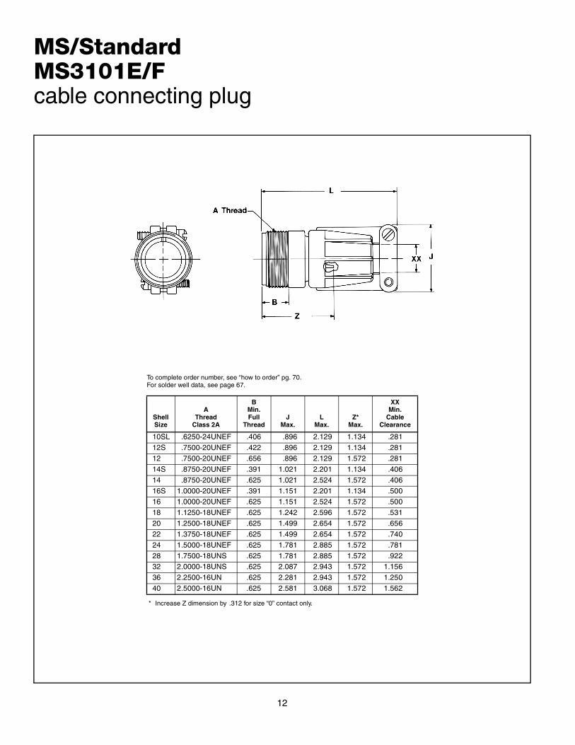
ShellSize
AThread
Class 2A
BMin.Full
ThreadJ
Max.L
Max.Z*
Max.
XXMin.
CableClearance
10SL .6250-24UNEF .406 .896 2.129 1.134 .281
12S .7500-20UNEF .422 .896 2.129 1.134 .281
12 .7500-20UNEF .656 .896 2.129 1.572 .281
14S .8750-20UNEF .391 1.021 2.201 1.134 .406
14 .8750-20UNEF .625 1.021 2.524 1.572 .406
16S 1.0000-20UNEF .391 1.151 2.201 1.134 .50016 1.0000-20UNEF .625 1.151 2.524 1.572 .500
18 1.1250-18UNEF .625 1.242 2.596 1.572 .531
20 1.2500-18UNEF .625 1.499 2.654 1.572 .656
22 1.3750-18UNEF .625 1.499 2.654 1.572 .740
24 1.5000-18UNEF .625 1.781 2.885 1.572 .781
28 1.7500-18UNS .625 1.781 2.885 1.572 .92232 2.0000-18UNS .625 2.087 2.943 1.572 1.156
36 2.2500-16UN .625 2.281 2.943 1.572 1.250
40 2.5000-16UN .625 2.581 3.068 1.572 1.562
MS/StandardMS3101E/Fcable connecting plug
To complete order number, see “how to order” pg. 70.For solder well data, see page 67.
* Increase Z dimension by .312 for size “0” contact only.

13
ShellSize
AThread
Class 2A
BMin.Full
Thread
K+.020–.010
L+.000–.010
M+.010–.000
NDia.
+.010–.000
R±.005
S±.031
TDia.
+.004–.002
Z+.050–.060
8S .5000-28UNEF .391 .672 .297 .562 .375 .594 .875 .120 .422
10S .6250-24NEF .391 .672 .297 .562 .500 .719 1.000 .120 .422
10SL .6250-24NEF .391 .672 .297 .562 .625 .719 1.000 .120 .422
12S .7500-20UNEF .450 .672 .297 .562 .625 .812 1.094 .120 .422
12 .7500-20UNEF .625 .860 .484 .750 .625 .812 1.094 .120 .672
14S .8750-20UNEF .450 .672 .297 .562 .750 .906 1.188 .120 .42214 .8750-20UNEF .625 .860 .484 .750 .750 .906 1.188 .120 .672
16S 1.0000-20UNEF .450 .672 .297 .562 .875 .969 1.281 .120 .422
16 1.0000-20UNEF .625 .860 .484 .750 .875 .969 1.281 .120 .672
18 1.1250-18NEF .625 .891 .453 .750 1.000 1.062 1.375 .120 .641*
20 1.2500-18NEF .625 .891 .453 .750 1.125 1.156 1.500 .120 .641*
22 1.3750-18NEF .625 .891 .453 .750 1.250 1.250 1.625 .120 .641*24 1.5000-18NEF .625 .953 .453 .812 1.375 1.375 1.750 .147 .578*
28 1.7500-18NS .625 .953 .453 .812 1.625 1.562 2.000 .147 .578*
32 2.0000-18NS .625 1.031 .438 .875 1.875 1.750 2.250 .173 .500*
36 2.2500-16UN .625 1.031 .438 .875 2.062 1.938 2.500 .173 .500*
40 2.5000-16UN .625 1.031 .438 .875 2.312 2.188 2.750 .173 .500*
MS/StandardMS3102Ebox mounting receptacle
To complete order number, see “how to order” pg. 70.For solder well data, see page 67.
* Increase Z dimension by .312 for size “0” contact only.

14
ShellSize
AThread
Class 2AB
±.005J
Max.L
Max.Q
Max.Z*
±.045
XXMin.
CableClearance
10SL .6250-24UNEF .531 .896 2.129 .946 .607 .281
12S .7500-20UNEF .531 .896 2.129 .995 .607 .281
12 .7500-20UNEF .719 .896 2.129 .995 .857 .281
14S .8750-20UNEF .531 1.021 2.201 1.123 .607 .406
14 .8750-20UNEF .719 1.021 2.524 1.123 .857 .406
16S 1.0000-20UNEF .531 1.151 2.201 1.250 .607 .50016 1.0000-20UNEF .719 1.151 2.524 1.250 .857 .500
18 1.1250-18UNEF .719 1.242 2.596 1.333 .857 .531
20 1.2500-18UNEF .719 1.499 2.654 1.461 .857 .656
22 1.3750-18UNEF .719 1.499 2.654 1.588 .857 .740
24 1.5000-18UNEF .719 1.781 2.885 1.715 .857 .781
28 1.7500-18UNS .719 1.781 2.885 1.968 .857 .92232 2.0000-18UNS .719 2.087 2.943 2.209 .857 1.156
36 2.2500-16UN .719 2.281 2.943 2.463 .857 1.250
40 2.5000-16UN .719 2.581 3.068 2.718 .857 1.562
MS/StandardMS3106E/Fstraight plug
To complete order number, see “how to order” pg. 70.For solder well data, see page 67.All lockwire holes are .045 dia. min.
* Increase Z dimension by .312 for size “0” contact only.

15
ShellSize
AThread
Class 2BJ
±.005L
Max.N
Max.
QDia.Max.
UMax.
YThread
Class 2BZ
±.045
8S .5000-28UNEF .531 .927 .807 .741 1.445 6-32NC .562
10S .6250-24NEF .531 .927 .807 .869 1.445 6-32NC .56210SL .6250-24NEF .531 .951 .901 .946 1.508 6-32NC .562
12S .7500-20UNEF .531 .956 .901 .995 1.508 6-32NC .562
12 .7500-20UNEF .719 1.143 .901 .995 1.508 6-32NC .812
14S .8750-20UNEF .531 1.020 1.026 1.123 1.570 6-32NC .562
14 .8750-20UNEF .719 1.207 1.026 1.123 1.570 6-32NC .812
16S 1.0000-20UNEF .531 1.146 1.119 1.250 1.633 6-32NC .56216 1.1000-20UNEF .719 1.333 1.119 1.250 1.633 6-32NC .812
18 1.1250-18NEF .719 1.395 1.229 1.333 1.759 6-32NC .812*
20 1.2500-18NEF .719 1.598 1.479 1.461 1.931 8-32NC .812*
22 1.3750-18NEF .719 1.598 1.479 1.588 1.993 8-32NC .812*
24 1.5000-18NEF .719 1.786 1.666 1.729 2.119 8-32NC .812*
28 1.7500-18NS .719 1.786 1.666 1.968 2.181 8-32NC .812*32 2.0000-18NS .719 2.020 2.135 2.209 2.570 10-32NF .812*
36 2.2500-16UN .719 2.145 2.260 2.463 2.695 10-32NF .812*
40 2.5000-16UN .719 2.270 2.510 2.719 2.851 10-32NF .812*
MS/StandardMS3108E90 degree plug
To complete order number, see “how to order” pg. 70.For solder well data, see page 67.All lockwire holes are .045 dia. min.
* Increase Z dimension by .312 for size “0” contact only.

MS/StandardMS-R
wall mounting receptacle
cable connecting plug
box mounting receptacle
6
1straight plug
MS-R
Specification requirements for greater reliability in ashorter, lighter weight environmental resistant connectorled to the design of the MS-R.
This low profile assembly was attained by moving theaxial compression nut and grommet assembly forwardand flush with the rear of the insert. The neoprene grom-met, with its low coefficient of friction, assures easierthreading of wire bundles and quicker assembly and ser-viceability of the unit. Molded webs in each wire holeinsure a moisture barrier around each wire.
The addition of an “O” ring at the main joint of allMS3106R plugs provide a main joint seal supplementaryto the interfacial seal, thus insuring a higher degree ofreliability when connector halves from different sourcesare employed. MS-R types are recommended for newdesign applications.
Shells:Shell components are fabricated from high grade alumi-num alloy. All components have the standard electricallyconductive cadmium plated finish with an olive drab chro-mate after-treatment for corrosion resistance. ConsultAmphenol, Sidney, NY for other plating options.
Contacts:Contacts are machined from copper alloy for maximumcorrosion resistance, maximum current carrying capacityand low millivolt drop. Both crimp and solder versions areavailable. Refer to pages 49, 67 and 68 for additionalcontact information.
Inserts:Resilient neoprene inserts provide an outstanding mois-ture barrier, maximum vibration resistance and highdielectric strength. Either pin or socket insert can bepressurized.

17
ShellSize
AThread
Class 2A
BMin.Full
Thread
HDia.Max.
K+.020–.010
LMax.
M+.010–.000
PDia.Max.
R±.005
S±.031
YThreadClass 2
TDia.
+.004–.002
Z+.050–.060
8S .5000-28UNEF .391 .959 .672 1.588 .562 .557 .594 .875 6-32NC .120 .422
10S .6250-24NEF .391 1.026 .672 1.588 .562 .682 .719 1.000 6-32NC .120 .422
10SL .6250-24NEF .391 1.120 .672 1.588 .562 .807 .719 1.000 6-32NC .120 .422
12S .7500-20UNEF .450 1.120 .672 1.588 .562 .807 .812 1.094 6-32NC .120 .422
12 .7500-20UNEF .625 1.120 .860 1.931 .750 .807 .812 1.094 6-32NC .120 .672
14S .8750-20UNEF .450 1.307 .672 1.588 .562 .932 .906 1.188 6-32NC .120 .42214 .8750-20UNEF .625 1.307 .860 1.931 .750 .932 .906 1.188 6-32NC .120 .672
16S 1.0000-20UNEF .450 1.432 .672 1.588 .562 1.057 .969 1.281 6-32NC .120 .422
16 1.0000-20UNEF .625 1.432 .860 1.931 .750 1.057 .969 1.281 6-32NC .120 .672
18 1.1250-18NEF .625 1.557 .891 1.931 .750 1.182 1.063 1.375 6-32NC .120 .641*
20 1.2500-18NEF .625 1.744 .891 1.931 .750 1.291 1.156 1.500 8-32NC .120 .641*
22 1.3750-18NEF .625 1.869 .891 1.931 .750 1.432 1.250 1.625 8-32NC .120 .641*24 1.5000-18NEF .625 1.994 .953 2.009 .812 1.557 1.375 1.750 8-32NC .147 .578*
28 1.7500-18NS .625 2.166 .953 2.009 .812 1.807 1.562 2.000 8-32NC .147 .578*
32 2.0000-18NS .625 2.541 1.031 2.072 .875 2.057 1.750 2.250 10-32NF .173 .500*
36 2.2500-16UN .625 2.729 1.031 2.072 .875 2.260 1.938 2.500 10-32NF .173 .500*
40 2.5000-16UN .625 2.979 1.031 2.072 .875 2.260 2.510 2.750 10-32NF .173 .500*
MS/StandardMS3100Rwall mounting receptacle
To complete order number, see “how to order” pg. 70.For solder well data, see page 67.All lockwire holes are .045 dia. min.
* Increase Z dimension by .312 for size “0” contact only.

MS/StandardMS3101Rcable connecting plug
To complete order number, see “how to order” pg. 70.
ShellSize
AThread
Class 2A
BMin.Full
Thread
FDia.Max.
JDia.Max.
LMax.
YThreadClass 2
Z±.040
8S .5000-28UNEF .406 .959 .557 1.588 6-32NC 1.094
10S .6250-24NEF .406 1.026 .682 1.588 6-32NC 1.094
10SL .6250-24NEF .406 1.120 .807 1.588 6-32NC 1.094
12S .7500-20UNEF .422 1.120 .807 1.588 6-32NC 1.094
12 .7500-20UNEF .656 1.120 .807 1.931 6-32NC 1.532
14S .8750-20UNEF .391 1.307 .932 1.588 6-32NC 1.09414 .8750-20UNEF .625 1.307 .932 1.931 6-32NC 1.532
16S 1.0000-20UNEF .391 1.432 1.057 1.588 6-32NC 1.094
16 1.0000-20UNEF .625 1.432 1.057 1.931 6-32NC 1.532
18 1.1250-18NEF .625 1.557 1.182 1.931 6-32NC 1.532*
20 1.2500-18NEF .625 1.744 1.291 1.931 8-32NC 1.532*
22 1.3750-18NEF .625 1.869 1.432 1.931 8-32NC 1.532*24 1.5000-18NEF .625 1.994 1.557 2.009 8-32NC 1.532*
28 1.7500-18NS .625 2.166 1.807 2.009 8-32NC 1.532*
32 2.0000-18NS .625 2.541 2.057 2.072 10-32NF 1.532*
36 2.2500-16UN .625 2.729 2.260 2.072 10-32NF 1.532*
40 2.5000-16UN .625 2.979 2.510 2.072 10-32NF 1.532*
For solder well data, see page 67.All lockwire holes are .045 dia. min.
* Increase Z dimension by .312 for size “0” contact only.
18

19
ShellSize
AThread
Class 2A
BMin.Full
Thread
K+.020–.010
L+.000–.010
M+.010–.000
NDia.
+.010–.000
R±.005
S±.031
TDia.
+.004–.002
Z+.050–.060
8S .5000-28UNEF .391 .672 .297 .562 .375 .594 .875 .120 .422
10S .6250-24NEF .391 .672 .297 .562 .500 .719 1.000 .120 .422
10SL .6250-24NEF .391 .672 .297 .562 .625 .719 1.000 .120 .422
12S .7500-20UNEF .450 .672 .297 .562 .625 .812 1.094 .120 .422
12 .7500-20UNEF .625 .860 .484 .750 .625 .812 1.094 .120 .672
14S .8750-20UNEF .450 .672 .297 .562 .750 .906 1.188 .120 .42214 .8750-20UNEF .625 .860 .484 .750 .750 .906 1.188 .120 .672
16S 1.0000-20UNEF .450 .672 .297 .562 .875 .969 1.281 .120 .422
16 1.0000-20UNEF .625 .860 .484 .750 .875 .969 1.281 .120 .672
18 1.1250-18NEF .625 .891 .453 .750 1.000 1.062 1.375 .120 .641*
20 1.2500-18NEF .625 .891 .453 .750 1.125 1.156 1.500 .120 .641*
22 1.3750-18NEF .625 .891 .453 .750 1.250 1.250 1.625 .120 .641*24 1.5000-18NEF .625 .953 .453 .812 1.375 1.375 1.750 .147 .578*
28 1.7500-18NS .625 .953 .453 .812 1.625 1.562 2.000 .147 .578*
32 2.0000-18NS .625 1.031 .438 .875 1.875 1.750 2.250 .173 .500*
36 2.2500-16UN .625 1.031 .438 .875 2.062 1.938 2.500 .173 .500*
40 2.5000-16UN .625 1.031 .438 .875 2.312 2.188 2.750 .173 .500*
MS/StandardMS3102Rbox mounting receptacle
To complete order number, see “how to order” pg. 70.For solder well data, see page 67.
* Increase Z dimension by .312 for size “0” contact only.

20
ShellSize
AThread
Class 2B
FDia.Max.
J±.005
LMax.
NDia.Max.
QDia.Max.
YThreadClass 2
Z±.045
8S .5000-28UNEF .959 .531 1.057 .557 .741 6-32NC .562
10S .6250-24NEF 1.026 .531 1.057 .682 .869 6-32NC .56210SL .6250-24NEF 1.120 .531 1.057 .807 .946 6-32NC .562
12S .7500-20UNEF 1.120 .531 1.057 .807 .995 6-32NC .562
12 .7500-20UNEF 1.120 .719 1.212 .807 .995 6-32NC .812
14S .8750-20UNEF 1.307 .531 1.057 .932 1.123 6-32NC .562
14 .8750-20UNEF 1.307 .719 1.212 .932 1.123 6-32NC .812
16S 1.0000-20UNEF 1.432 .531 1.057 1.057 1.250 6-32NC .56216 1.0000-20UNEF 1.432 .719 1.212 1.057 1.250 6-32NC .812
18 1.1250-18NEF 1.557 .719 1.212 1.182 1.333 6-32NC .812*
20 1.2500-18NEF 1.744 .719 1.212 1.291 1.461 8-32NC .812*
22 1.3750-18NEF 1.869 .719 1.212 1.432 1.588 8-32NC .812*
24 1.5000-18NEF 1.994 .719 1.291 1.557 1.715 8-32NC .812*
28 1.7500-18NS 2.166 .719 1.291 1.807 1.968 8-32NC .812*32 2.0000-18NS 2.541 .719 1.353 2.057 2.209 10-32NF .812*
36 2.2500-16UN 2.729 .719 1.353 2.260 2.463 10-32NF .812*
40 2.5000-16UN 2.979 .719 1.353 2.510 2.719 10-32NF .812*
MS/StandardMS3106Rstraight plug
To complete order number, see “how to order” pg. 70.For solder well data, see page 67.All lockwire holes are .045 dia. min.
* Increase Z dimension by .312 for size “0” contact only.

21
MS/Standardcontact andinsert arrangements

MS/Standardinsert arrangements
InsertArrangement
ServiceRating
TotalContacts
Contact Size
0 4 8 12 16
8S-1 A 1 1
10S-2 A 1 1
10SL-3 A 3 3
10SL-4† A 2 2
12S-3 A 2 2
12S-4 D 1 1
12-5 D 1 1
14S-2 Inst. 4 4
14S-4 D 1 1
14S-5 Inst. 5 5
14S-6 Inst. 6 6
14S-7 A 3 3
14S-9 A 2 2
14S-10 Inst. 4 4
14S-12 A 3 3
14-3 A 1 1
16S-1 A 7 7
16S-3 B 1 1
16S-4 D 2 2
16S-5 A 3 3
16S-6 A 3 3
16S-8 A 5 5
16-2 E 1 1
16-7 A 3 1 2
16-9 A 4 2 2
16-10 A 3 3
16-11 A 2 2
16-12 A 1 1
16-13 A 2 2
18-1 A/Inst. 10 10
18-3 D 2 2
18-4 D 4 4
18-5 D 3 2 1
18-6 D 1 1
18-7 B 1 1
18-8 A 8 1 7
18-9 Inst. 7 2 5
18-10 A 4 4
18-11 A 5 5
18-12 A 6 6
18-13 A 4 1 3
18-14 A 2 1 1
18-15 A 4 4
18-16 C 1 1
18-17 Inst. 7 2 5
18-19 A 10 10
18-20 A 5 5
18-22 D 3 3
18-24 A/Inst. 10 10
18-29 A 5 5
18-30 A 5 5
22
† 10SL-4 arrangement available only with pin contacts in receptacle and socketcontacts in plug
18-31 A 5 5
20-2 D 1 1
20-3 D 3 3
20-4 D 4 4
20-6 D 3 3
20-7 D/A 8 8
20-8 Inst. 6 2 4
20-9 D/A 8 1 7
20-11 Inst. 13 13
20-12 A 2 1 1
20-14 A 5 2 3
20-15 A 7 7
20-16 A 9 2 7
20-17 A 6 5 1
20-18 A 9 3 6
20-19 A 3 3
20-20 A 4 1 3
20-21 A 9 1 8
20-22 A 6 3 3
20-23 A 2 2
20-24 A 4 2 2
20-25 Inst. 13 13
20-27 A 14 14
20-29 A 17 17
20-30 Inst. 13 13
20-33 A 11 11
22-1 D 2 2
22-2 D 3 3
22-4 A 4 2 2
22-5 D 6 2 4
22-6 D 3 2 1
22-7 E 1 1
22-8 E 2 2
22-9 E 3 3
22-10 E 4 4
22-11 B 2 2
22-12 D 5 2 3
22-13 D/A 5 4 1
22-14 A 19 19
22-15 E/A 6 5 1
22-16 A 9 3 6
22-17 D/A 9 1 8
22-18 D/A 8 8
22-19 A 14 14
22-20 A 9 9
22-21 A 3 1 2
22-22 A 4 4
22-23 D/A 8 8
22-24 D/A 6 2 4
22-27 D/A 9 1 8
22-28 A 7 7
InsertArrangement
ServiceRating
TotalContacts
Contact Size
0 4 8 12 16

MS/Standardinsert arrangements, cont.
InsertArrangement
ServiceRating
TotalContacts
Contact Size
0 4 8 12 16
22-33 D/A 7 7
22-34 D 5 3 2
24-2 D 7 7
24-3 D 7 2 5
24-5 A 16 16
24-6 D/A 8 8
24-7 A 16 2 14
24-9 A 2 2
24-10 A 7 7
24-11 A 9 3 6
24-12 A 5 2 3
24-16 D/A 7 1 3 3
24-17 D 5 2 3
24-20 D 11 2 9
24-21 D 10 1 9
24-22 D 4 4
24-27 E 7 7
24-28 Inst. 24 24
28-1 D/A 9 3 6
28-2 D 14 2 12
28-3 E 3 3
28-4 E/D 9 2 7
28-5 D 5 2 1 2
28-6 D 3 3
28-7 D 2 2
28-8 E/D/A 12 2 10
28-9 D 12 6 6
28-10 D/A 7 2 2 3
28-11 A 22 4 18
28-12 A 26 26
28-13 A 26 26
28-15 A 35 35
28-16 A 20 20
28-17 B/D/A 15 15
28-18 C/D/A/Inst. 12 12
28-19 B/D/A 10 4 6
28-20 A 14 10 4
28-21 A 37 37
28-22 D 6 3 3
23
32-1 E/D 5 2 3
32-2 E 5 3 2
32-3 D 9 1 2 2 4
32-4 A/D 14 2 12
32-5 D 2 2
32-6 A 23 2 3 2 16
32-7 Inst./A 35 7 28
32-8 A 30 6 24
32-9 D 14 2 12
32-10 E/B/D/A 7 2 2 3
32-12 A/D 15 5 10
32-13 D 23 5 18
32-15 D 8 2 6
32-16 A 23 2 3 2 16
32-17 D 4 4
32-22 A 54 54
36-1 D 22 4 18
36-3 D 6 3 3
36-4 D/A 3 3
36-5 A 4 4
36-6 A 6 2 4
36-7 A 47 7 40
36-8 A 47 1 46
36-9 A 31 1 2 14 14
36-10 A 48 48
36-11 A 48 48
36-12 A 48 48
36-13 E/A 17 2 15
36-14 D 16 5 5 6
36-15 D/A 35 35
36-16 A 47 7 40
36-17 A 47 7 40
36-18 A 31 1 2 14 14
36-20 A 34 2 2 30
36-52 A 52 52
40-1 D 30 6 24
40-9 A 47 1 22 24
40-56 A 85 85
48-62 D 85 85
InsertArrangement
ServiceRating
TotalContacts
Contact Size
0 4 8 12 16
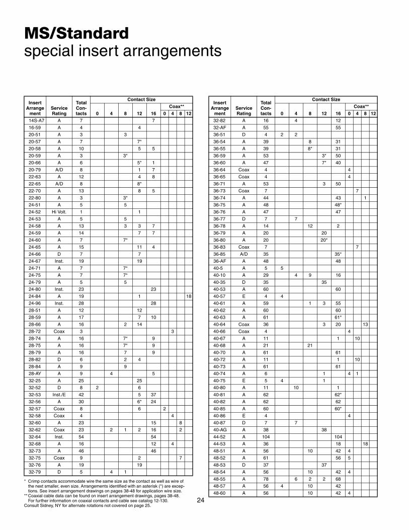
MS/Standardspecial insert arrangements
InsertArrange
mentServiceRating
TotalCon-tacts
Contact Size
0 4 8 12 16
Coax**
0 4 8 12
14S-A7 A 7 7
16-59 A 4 4
20-51 A 3 3
20-57 A 7 7*
20-58 A 10 5 5
20-59 A 3 3*
20-66 A 6 5* 1
20-79 A/D 8 1 7
22-63 A 12 4 8
22-65 A/D 8 8*
22-70 A 13 8 5
22-80 A 3 3*
24-51 A 5 5
24-52 Hi Volt. 1 1
24-53 A 5 5
24-58 A 13 3 3 7
24-59 A 14 7 7
24-60 A 7 7*
24-65 A 15 11 4
24-66 D 7 7
24-67 Inst. 19 19
24-71 A 7 7*
24-75 A 7 7*
24-79 A 5 5
24-80 Inst. 23 23
24-84 A 19 1 18
24-96 Inst. 28 28
28-51 A 12 12
28-59 A 17 7 10
28-66 A 16 2 14
28-72 Coax 3 3
28-74 A 16 7* 9
28-75 A 16 7* 9
28-79 A 16 7 9
28-82 D 6 2 4
28-84 A 9 9
28-AY A 9 4 5
32-25 A 25 25
32-52 D 8 2 6
32-53 Inst./E 42 5 37
32-56 A 30 6* 24
32-57 Coax 8 6 2
32-58 Coax 4 4
32-60 A 23 15 8
32-62 Coax 23 2 1 2 16 2
32-64 Inst. 54 54
32-68 A 16 12 4
32-73 A 46 46
32-75 Coax 9 2 7
32-76 A 19 19
32-79 D 5 4 1
* Crimp contacts accommodate wire the same size as the contact as well as wire of the next smaller, even size. Arrangements identified with an asterisk (*) are excep-
24
tions. See insert arrangement drawings on pages 38-48 for application wire size.** Coaxial cable data can be found on insert arrangement drawings, pages 38-48.
For further information on coaxial contacts and cable see catalog 12-130.Consult Sidney, NY for alternate rotations not covered on page 25.
32-82 A 16 4 12
32-AF A 55 55
36-51 D 4 2 2
36-54 A 39 8 31
36-55 A 39 8* 31
36-59 A 53 3* 50
36-60 A 47 7* 40
36-64 Coax 4 4
36-65 Coax 4 4
36-71 A 53 3 50
36-73 Coax 7 7
36-74 A 44 43 1
36-75 A 48 48*
36-76 A 47 47
36-77 D 7 7
36-78 A 14 12 2
36-79 A 20 20
36-80 A 20 20*
36-83 Coax 7 7
36-85 A/D 35 35*
36-AF A 48 48
40-5 A 5 5
40-10 A 29 4 9 16
40-35 D 35 35
40-53 A 60 60
40-57 E 4 4
40-61 A 59 1 3 55
40-62 A 60 60
40-63 A 61 61*
40-64 Coax 36 3 20 13
40-66 Coax 4 4
40-67 A 11 1 10
40-68 A 21 21
40-70 A 61 61
40-72 A 11 1 10
40-73 A 61 61
40-74 A 6 1 4 1
40-75 E 5 4 1
40-80 A 11 10 1
40-81 A 62 62*
40-82 A 62 62
40-85 A 60 60*
40-86 E 4 4
40-87 D 7 7
40-AG A 38 38
44-52 A 104 104
44-53 A 36 18 18
48-51 A 56 10 42 4
48-52 A 61 56 5
48-53 D 37 37
48-54 A 56 10 42 4
48-55 A 78 6 2 2 68
48-57 A 56 4 10 42
48-60 A 56 10 42 4
InsertArrange
mentServiceRating
TotalCon-tacts
Contact Size
0 4 8 12 16
Coax**
0 4 8 12

MS/Standardinsert alternate positioning
To avoid cross-plugging problems in applications requir-ing the use of more than one connector of the same sizeand arrangement, alternate rotations are available asindicated in the accompanying charts.
As shown in the diagram below, the front face of the pininsert is rotated within the shell in a clockwise directionfrom the normal shell key. The socket insert would berotated counter-clockwise the same number of degrees inrespect to the normal shell key.
Position W Position X Position Y Position Z
View looking into front face of pin insert or rear of socket insert.
The following insert arrangements have the same alter-nate insert rotations for W, X, Y and Z, which are:
Degrees
W X Y Z
80 110 250 280
16-7 20-16 22-19 24-5 28-1 28-19 32-13
18-5 20-20 22-21 24-6 28-4 28-20 32-22
18-9 20-22 22-24 24-7 28-8 28-21 32-AF
18-13 22-6 22-25 24-12 28-9 32-1 36-1
18-14 22-12 22-29 24-14 28-10 32-3 36-7
20-7 22-14 22-33 24-16 28-11 32-4 36-8
20-8 22-15 22-34 24-17 28-14 32-6 36-13
20-9 22-16 24-1 24-20 28-15 32-9
20-12 22-17 24-3 24-21 28-16 32-10
20-14 22-18 24-4 24-28 28-17 32-12
InsertArrangement
Degrees
W X Y Z
10SL-4 63 – – –
12S-3 70 145 215 290
14S-2 – 120 240 –
14S-5 – 110 – –
14S-7 90 180 270 –
14S-9 70 145 215 290
16-9 35 110 250 325
16-10 90 180 270 –
16-11 35 110 250 325
16-13 35 110 250 325
16S-1 80 – – 280
16S-4 35 110 250 325
16S-5 70 145 215 290
16S-6 90 180 270 –
16S-8 – 170 265 –
18-1 70 145 215 290
18-3 35 110 250 325
18-4 35 110 250 325
18-8 70 – – 290
18-10 – 120 240 –
18-11 – 170 265 –
18-12 80 – – 280
18-15 – 120 240 –
18-20 90 180 270 –
18-22 70 145 215 290
18-29 90 180 270 –
20-3 70 145 215 290
20-4 45 110 250 –
20-5 35 110 250 325
20-6 70 145 215 290
20-15 80 – – 280
20-17 90 180 270 –
20-18 35 110 250 325
20-19 90 180 270 –
20-21 35 110 250 325
20-23 35 110 250 325
20-24 35 110 250 325
20-27 35 110 250 325
20-29 80 – – 280
22-1 35 110 250 325
22-2 70 145 215 290
22-4 35 110 250 325
22-5 35 110 250 325
22-8 35 110 250 325
22-9 70 145 215 290
22-10 35 110 250 325
22-11 35 110 250 325
22-13 35 110 250 325
22-20 35 110 250 325
22-22 – 110 250 –
22-23 35 – 250 –
22-27 80 – 250 280
22-28 80 – – 280
22-63 20 – – –
24-2 80 – – 280
24-9 35 110 250 325
24-10 80 – – 280
24-11 35 110 250 325
24-22 45 110 250 –
24-27 80 – – 280
28-2 35 110 250 325
28-3 70 145 215 290
InsertArrangement
Degrees
W X Y Z
25
28-5 35 110 250 325
28-6 70 145 215 290
28-7 35 110 250 325
28-12 90 180 270 –
28-18 70 145 215 290
28-22 70 145 215 290
28-AY 45 110 250 –
32-2 70 145 215 290
32-5 35 110 250 325
32-7 80 125 235 280
32-8 80 125 235 280
32-15 35 110 250 280
32-17 45 110 250 –
32-25 60 120 – –
32-64 80 100 110 250
32-68 30 – – –
32-82 30 – – –
36-3 70 145 215 290
36-4 70 145 215 290
36-5 – 120 240 –
36-6 35 110 250 325
36-9 80 125 235 280
36-10 80 125 235 280
36-14 90 180 270 –
36-15 60 125 245 305
36-AF 65 – – –
40-1 65 130 235 300
40-5 33 – – 270
40-9 65 125 225 310
40-10 65 125 225 310
40-35 70 130 230 290
40-AG 37 74 285 322
InsertArrangement
Degrees
W X Y Z

MS/Standardcontact arrangements
front face of pin insert or rear face of socket insert illustrated
Front of Front of
Insert Arrangement 8S-1 10S-2 10SL-3 10SL-4 12S-3 12S-4 12-5
Service Rating A A A A A D D
Number of Contacts 1 1 3 2 2 1 1
Contact Size 16 16 16 16 16 16 12
Socket Insert Socket Insert
Insert Arrangement 14S-2 14S-4 14S-5 14S-6 14S-7 14S-9
Service Rating Inst. D Inst. Inst. A A
Number of Contacts 4 1 5 6 3 2
Contact Size 16 16 16 16 16 16
100° Rotation 100° Rotation
Insert Arrangement 14S-10 14S-12 14-3 16S-1 16S-3 16S-4
Service Rating Inst. A A A B D
Number of Contacts 4 3 1 7 1 2
Contact Size 16 16 8 16 16 16
of 14S-2 of 14S-7
Insert Arrangement 16S-5 16S-6 16S-8 16-2 16-7 16-9
Service Rating A A A E A A
Number of Contacts 3 3 5 1 1 2 2 2
Contact Size 16 16 16 12 8 16 12 16
CONTACT LEGEND 16 12 8 4 0
26

MS/Standardcontact arrangements
front face of pin insert or rear face of socket insert illustrated
Insert Arrangement 16-10 16-11 16-12 16-13 18-1 18-3
Service Rating A A A A B, C, F, G = A; Bal. = Inst. D
Number of Contacts 3 2 1 2* 10 2
Contact Size 12 12 4 12 16 12
Insert Arrangement 18-4 18-5 18-6 18-7 18-8 18-9
Service Rating D D D B A Inst.
Number of Contacts 4 2 1 1 1 1 7 2 5
Contact Size 16 12 16 4 8 12 16 12 16
Insert Arrangement 18-10 18-11 18-12 18-13 18-14 18-15
Service Rating A A A A A A
Number of Contacts 4 5 6 1 3 1 1 4**
Contact Size 12 12 16 8 12 4 16 12
100° Rotation 250° Rotation
Insert Arrangement 18-16 18-17 18-19 18-20 18-22 18-24
Service Rating C Inst. A A D B, C, F, G = A; Bal. = Inst.
Number of Contacts 1 2 5 10 5 3 10
Contact Size 12 12 16 16 16 16 16
of 18-9 of 18-1
CONTACT LEGEND 16 12 8 4 0
* A = Iron; B = Constantan
27
** A, C = Iron; B, D = Constantan
MS/Standardcontact arrangements
front face of pin insert or rear face of socket insert illustrated
110° Rotation 260° Rotation
Insert Arrangement 18-29 18-30 18-31 20-2 20-3 20-4
Service Rating A A A D D D
Number of Contacts 5 5 5 1 3 4
Contact Size 16 16 16 0 12 12
of 18-20 of 18-20
Insert Arrangement 20-6 20-7 20-8 20-9 20-11 20-12
Service Rating D A, B, H, G = D; C, D, E, F = A Inst. H = D; Bal. = A Inst. A
Number of Contacts 3 8 2 4 1 7 13 1 1
Contact Size 16 16 8 16 12 16 16 4 16
Insert Arrangement 20-14 20-15 20-16 20-17 20-18 20-19
Service Rating A A A A A A
Number of Contacts 2 3 7 2 7 5 1 3 6 3
Contact Size 8 12 12 12 16 12 16 12 16 8
CONTACT LEGEND 16 12 8 4 0
28

MS/Standardcontact arrangements
front face of pin insert or rear face of socket insert illustrated
100° Rotation
Insert Arrangement 20-20 20-21 20-22 20-23 20-24 20-25
Service Rating A A A A A Inst.
Number of Contacts 1 3 1 8 3 3 2 2 2 13
Contact Size 4 12 12 16 8 16 8 8 16 16
of 20-11
250° Rotation
Insert Arrangement 20-27 20-29 20-30 20-33 22-1 22-2
Service Rating A A Inst. A D D
Number of Contacts 14 17 13 11 2 3
Contact Size 16 16 16 16 8 8
of 20-11
Insert Arrangement 22-4 22-5 22-6 22-7 22-8
Service Rating A D D E E
Number of Contacts 2 2 2 4 2 1 1 2
Contact Size 8 12 12 16 8 16 0 12
CONTACT LEGEND 16 12 8 4 0
29

MS/Standardcontact arrangements
front face of pin insert or rear face of socket insert illustrated
Insert Arrangement 22-9 22-10 22-11 22-12 22-13
Service Rating E E B D E = D; A, B, C, D = A
Number of Contacts 3 4 2 2 3 4 1
Contact Size 12 16 16 8 16 12 16
Insert Arrangement 22-14 22-15 22-16 22-17 22-18
Service Rating A D = E; A, B, C, E, F = A A A = D; Bal. = A A, B, F, G, H = D; C, D, E = A
Number of Contacts 19 5 1 3 6 1 8 8
Contact Size 16 12 16 12 16 12 16 16
Insert Arrangement 22-19 22-20 22-21 22-22 22-23
Service Rating A A A A H = D; Bal. = A
Number of Contacts 14 9 1 2 4 8
Contact Size 16 16 0 16 8 12
CONTACT LEGEND 16 12 8 4 0
30

MS/Standardcontact arrangements
front face of pin insert or rear face of socket insert illustrated
Insert Arrangement 22-24 22-27 22-28 22-33 22-34
Service Rating C, D, E = D; A, B, F = A J = D; Bal. = A A A, B, C, D = D; E, F, G = A D
Number of Contacts 2 4 1 8 7 7 3 2
Contact Size 12 16 8 16 12 16 12 16
Insert Arrangement 24-2 24-3 24-5 24-6 24-7
Service Rating D D A A, G, H = D; Bal. = A A
Number of Contacts 7 2 5 16 8 2 14
Contact Size 12 12 16 16 12 12 16
Insert Arrangement 24-9 24-10 24-11 24-12 24-16
Service Rating A A A A A, B, F, G = D; C, D, E = A
Number of Contacts 2 7 3 6 2 3 1 3 3
Contact Size 4 8 8 12 4 12 8 12 16
CONTACT LEGEND 16 12 8 4 0
31

MS/Standardcontact arrangements
front face of pin insert or rear face of socket insert illustrated
Insert Arrangement 24-17 24-20 24-21 24-22 24-27
Service Rating D D D D E
Number of Contacts 2 3 2 9 1 9 4 7
Contact Size 12 16 12 16 8 16 8 16
Insert Arrangement 24-28 28-1 28-2 28-3
Service Rating Inst. A, J, E = D; Bal. = A D E
Number of Contacts 24 3 6 2 12 3
Contact Size 16 8 12 12 16 8
Insert Arrangement 28-4 28-5 28-6 28-7
Service Rating G, P, S = E; Bal. = D D D D
Number of Contacts 2 7 2 1 2 3 2
Contact Size 12 16 4 12 16 4 4
CONTACT LEGEND 16 12 8 4 0
32

MS/Standardcontact arrangements
front face of pin insert or rear face of socket insert illustrated
Insert Arrangement 28-8 28-9 28-10 28-11
Service Rating L, M = E; B = D; Bal. = A D G = D; Bal. = A A
Number of Contacts 2 10 6 6 2 2 3 4 18
Contact Size 12 16 12 16 4 8 12 12 16
100° Rotation
Insert Arrangement 28-12 28-13 28-15 28-16
Service Rating A A A A
Number of Contacts 26 26 35 20
Contact Size 16 16 16 16
of 28-12
Insert Arrangement 28-17 28-18 28-19
Service Rating R = B; M, N, P = D; A to L = A M = C; G, H, J, K, L = D; A, B = A; Bal. = Inst. H, M = B; A, B = D; Bal. = A
Number of Contacts 15 12 4 6
Contact Size 16 16 12 16
CONTACT LEGEND 16 12 8 4 0
33
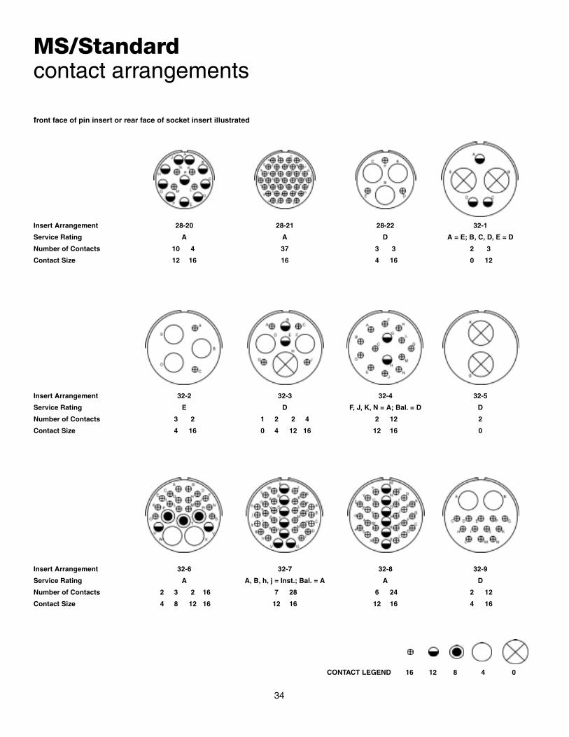
MS/Standardcontact arrangements
front face of pin insert or rear face of socket insert illustrated
Insert Arrangement 28-20 28-21 28-22 32-1
Service Rating A A D A = E; B, C, D, E = D
Number of Contacts 10 4 37 3 3 2 3
Contact Size 12 16 16 4 16 0 12
Insert Arrangement 32-2 32-3 32-4 32-5
Service Rating E D F, J, K, N = A; Bal. = D D
Number of Contacts 3 2 1 2 2 4 2 12 2
Contact Size 4 16 0 4 12 16 12 16 0
Insert Arrangement 32-6 32-7 32-8 32-9
Service Rating A A, B, h, j = Inst.; Bal. = A A D
Number of Contacts 2 3 2 16 7 28 6 24 2 12
Contact Size 4 8 12 16 12 16 12 16 4 16
CONTACT LEGEND 16 12 8 4 0
34

MS/Standardcontact arrangements
front face of pin insert or rear face of socket insert illustrated
Insert Arrangement 32-10 32-12 32-13 32-15
Service Rating A, F = E; G = B; B, E = D; C, D = A C, D, E, F, G = A; Bal. = D D D
Number of Contacts 2 2 3 5 10 5 18 2 6
Contact Size 4 8 16 12 16 12 16 0 12
100° Rotation
Insert Arrangement 32-16 32-17 32-22 36-1
Service Rating A D A D
Number of Contacts 2 3 2 16 4 54 4 18
Contact Size 4 8 12 16 4 16 12 16
of 32-6
Insert Arrangement 36-3 36-4 36-5 36-6
Service Rating D A = D; B, C = A A A
Number of Contacts 3 3 3 4 2 4
Contact Size 0 12 0 0 0 4
CONTACT LEGEND 16 12 8 4 0
35

MS/Standardcontact arrangements
front face of pin insert or rear face of socket insert illustrated
Insert Arrangement 36-7 36-8 36-9
Service Rating A A A
Number of Contacts 7 40 1 46 1 2 14 14
Contact Size 12 16 12 16 4 8 12 16
100° Rotation 110° Rotation
Insert Arrangement 36-10 36-11 36-12
Service Rating A A A
Number of Contacts 48 48 48
Contact Size 16 16 16
of 36-10 of 36-10
Insert Arrangement 36-13 36-14 36-15
Service Rating N, P, Q = E; Bal. = A D M = D; Bal. = A
Number of Contacts 2 15 5 5 6 35
Contact Size 12 16 8 12 16 16
CONTACT LEGEND 16 12 8 4 0
36
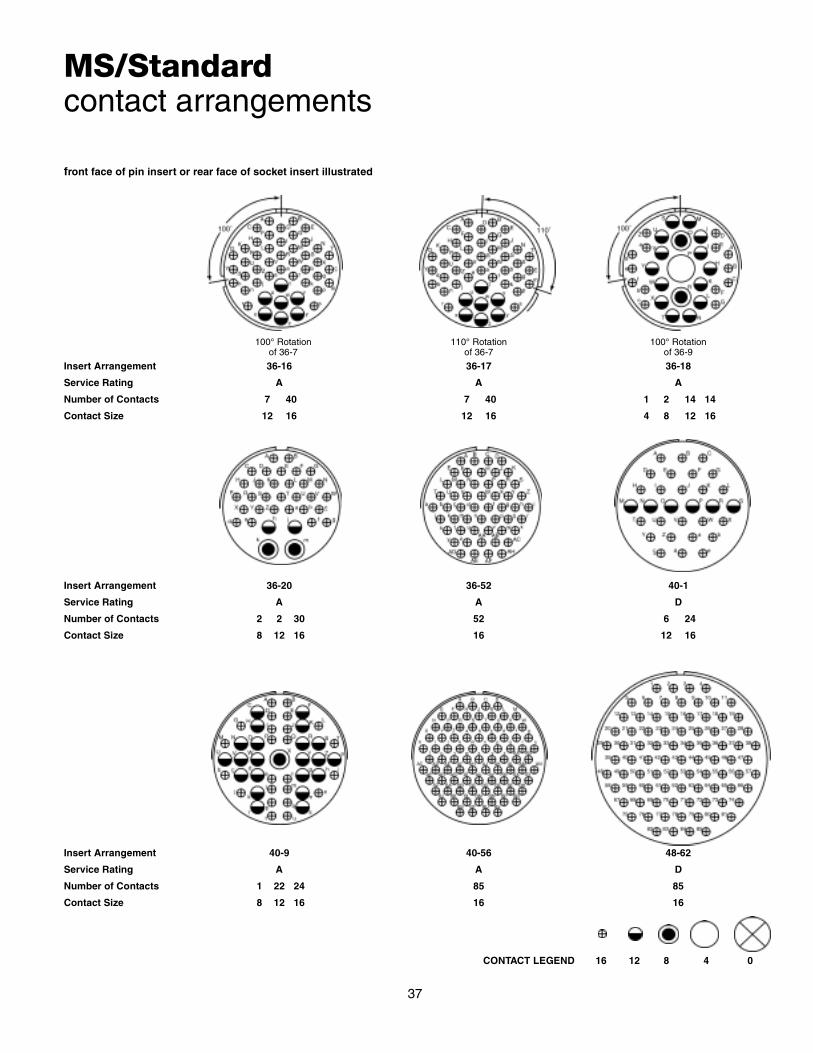
MS/Standardcontact arrangements
front face of pin insert or rear face of socket insert illustrated
110° Rotation 100° Rotation100° Rotation
Insert Arrangement 36-16 36-17 36-18
Service Rating A A A
Number of Contacts 7 40 7 40 1 2 14 14
Contact Size 12 16 12 16 4 8 12 16
of 36-7 of 36-9of 36-7
Insert Arrangement 36-20 36-52 40-1
Service Rating A A D
Number of Contacts 2 2 30 52 6 24
Contact Size 8 12 16 16 12 16
Insert Arrangement 40-9 40-56 48-62
Service Rating A A D
Number of Contacts 1 22 24 85 85
Contact Size 8 12 16 16 16
CONTACT LEGEND 16 12 8 4 0
37

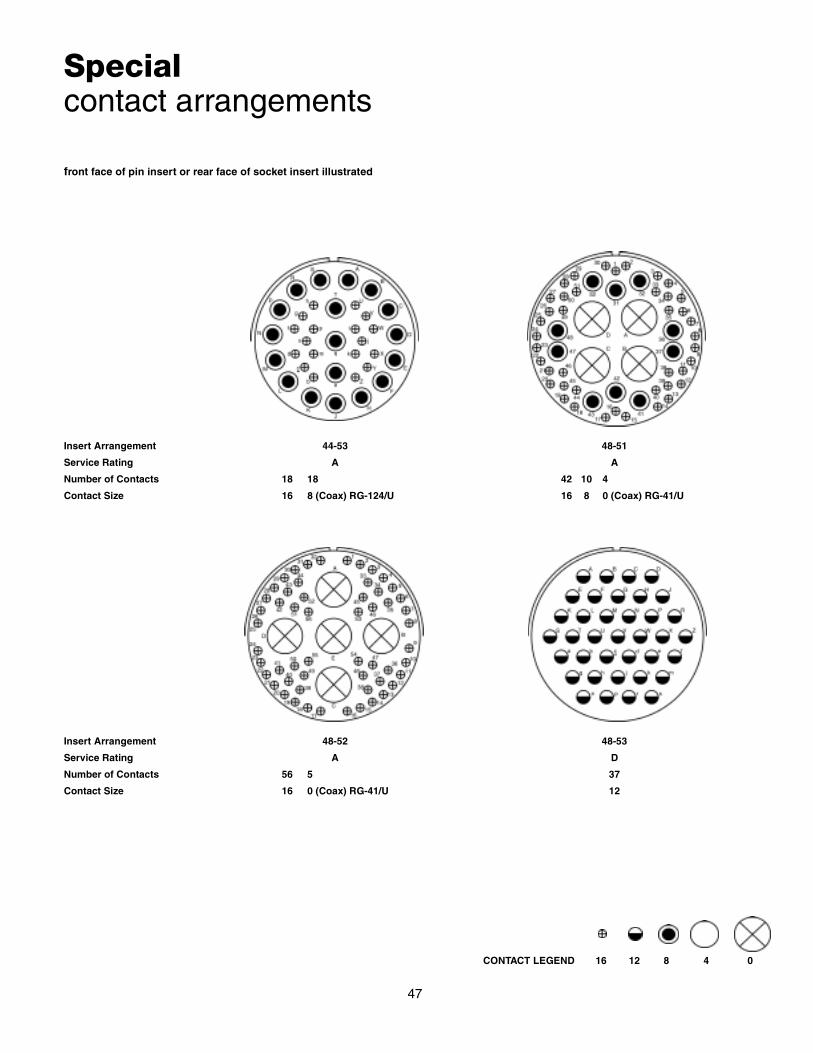
Specialcontact arrangements
Requirements for more complex circuits promptedAmphenol to provide inserts not covered by the MS draw-ings. Illustrated here and on the following pages areinsert layouts which have from one contact (high tension)to the 104 contact insert in shell size 44.
38
Many of these special inserts are also available in alter-nate keyway arrangements. Please contact Amphenol,Sidney, NY for additional information on special circuitapplication requirements.
front face of pin insert or rear face of socket insert illustrated
Insert Arrangement 14S-A7 16-59 20-51 20-57 20-58 20-59
Service Rating A A A A A A
Number of Contacts 7 4 3* 7* 5 5 3*
Contact Size 16 12 8 12 for #14 or 16 wire 12 16 8 for #10 or 12 wire
Insert Arrangement 20-66 20-79 22-63 22-65 22-70
Service Rating A H = D; Bal. = A A H = D; Bal. = A A
Number of Contacts 1 5 7* 1* 4 8 8* 8 5
Contact Size 16 12 for #10 wire 16 12 for #16 wire 12 16 12 for #14 or 16 wire 12 16
Insert Arrangement 22-80 24-51 24-52 24-53 24-58
Service Rating A A Hi-Volt A A
Number of Contacts 3* 5* 1 5* 3 3 7
Contact Size 8 for #10 or 12 wire B, E for AN #10 or 12 wire 12 8 8 12 16A, C, D for AN #8 wire
* Solderless CONTACT LEGEND 16 12 8 4 0

Specialcontact arrangements
front face of pin insert or rear face of socket insert illustrated
Insert Arrangement 24-59 24-60 24-65 24-66
Service Rating A A A D
Number of Contacts 7 7 7* 11 4 7
Contact Size 12 16 8 for #10 or 12 wire 12 16 12
Insert Arrangement 24-67 24-71 24-75 24-79
Service Rating Inst. A A A
Number of Contacts 19 2* 5* 5 2 5
Contact Size 12 8 8 for #10 or 12 wire 8 8 for #16 wire 8
Insert Arrangement 24-80 24-84 24-96 28-51
Service Rating Inst. A Inst. A
Number of Contacts 23 1 18 28 12
Contact Size 16 12 12 (Coax) RG-188/U 16 12or RG-174/U
* Solderless CONTACT LEGEND 16 12 8 4 0
39

Specialcontact arrangements
front face of pin insert or rear face of socket insert illustrated
Insert Arrangement 28-59 28-66 28-72 28-74
Service Rating A A – A
Number of Contacts 7 10 2 14 3 9* 4* 3*
Contact Size 12 16 8 12 4 (Coax) RG-59A/U 16 8 8 for #10 wireor RG-62A/U (S, T, R)
Insert Arrangement 28-75 28-79 28-82 28-84
Service Rating A A D A
Number of Contacts 9* 7* 7 9 2 4 9
Contact Size 16 8 for #10 wire 8 16 8 12 8
90° CW Rotation
Insert Arrangement 28-AY 32-25 32-52 32-53
Service Rating A A D t, u = E; Bal. = Inst.
Number of Contacts 4 5 25 6 2 5 37
Contact Size 4 16 12 12 0 12 16
of 32-15
* Solderless CONTACT LEGEND 16 12 8 4 0
40

Specialcontact arrangements
front face of pin insert or rear face of socket insert illustrated
Insert Arrangement 32-56 32-57 32-58 32-60
Service Rating A ** – A
Number of Contacts 24 6 6 2 4 15 8
Contact Size 16 12 for #10 wire 12 0 (Coax) RG-71/U 4 (Coax) RG-161/U 16 8 (Coax) RG-124/Uor RG-179/U
Insert Arrangement 32-62 32-64 32-68
Service Rating ** Inst. A
Number of Contacts 2 1 2 16 2 54 12 4
Contact Size 4 8 12 16 8 (Coax) RG-124/U 16 16 4 (Coax) RG-58C/U
Insert Arrangement 32-73 32-75 32-76 32-79
Service Rating A 8, 9 = D A D
Number of Contacts 46 2 7 19 4 1
Contact Size 16 12 8 (Coax) RG-180B/U 12 4 8
** Consult Amphenol, Sidney, NY for service rating of power contacts. CONTACT LEGEND 16 12 8 4 0
41

Specialcontact arrangements
front face of pin insert or rear face of socket insert illustrated
Insert Arrangement 32-82 32-AF 36-51 36-54
Service Rating A A D A
Number of Contacts 4 12 55 2 2 8 31
Contact Size 4 16 16 0 4 8 16
Insert Arrangement 36-55 36-59 36-60 36-64
Service Rating A A ** –
Number of Contacts 31 8 50 3 40 7 4
Contact Size 16 8 for #6 wire 16 12 for #10 wire 16 12 for #10 wire 0 (Coax) RG-11/U,RG-12/U or RG-13/U
Insert Arrangement 36-65 36-71 36-73 36-74
Service Rating – A – A
Number of Contacts 4 3 50 7 43 1
Contact Size 0 (Coax) RG-59/U, RG-62/U 12 16 4 (Coax) RG-62B/U 16 8 (Coax) RG-187/Uor RG-71/U
** Consult Amphenol, Sidney, NY for service rating of power contacts. CONTACT LEGEND 16 12 8 4 0
42

Specialcontact arrangements
front face of pin insert or rear face of socket insert illustrated
Insert Arrangement 36-75 36-76 36-77 36-78
Service Rating A A D A
Number of Contacts 48 47 7 2 12
Contact Size 16 for #14 wire 16 4 16 8
Insert Arrangement 36-79 36-80 36-83
Service Rating A A –
Number of Contacts 20 20 7
Contact Size 12 12 for #10 wire 4 (Coax) RG-58/U
Insert Arrangement 36-85 36-AF 40-5
Service Rating M = D; Bal. = A A A
Number of Contacts 35 48 5
Contact Size 16 for #12 wire 16 0
CONTACT LEGEND 16 12 8 4 0
43

Specialcontact arrangements
front face of pin insert or rear face of socket insert illustrated
Insert Arrangement 40-10 40-35 40-53
Service Rating A D A
Number of Contacts 4 9 16 35 60
Contact Size 4 8 16 12 16
Insert Arrangement 40-57 40-61 40-62
Service Rating E A A
Number of Contacts 4 1 3 55 60
Contact Size 0 8 12 16 16
Insert Arrangement 40-63 40-64 40-66
Service Rating A – –
Number of Contacts 61 3 20 13 4
Contact Size 16 for #14 wire 12 16 8 (Coax) RG-124/U 0 (Coax) RG-63B/U
CONTACT LEGEND 16 12 8 4 0
44

Specialcontact arrangements
front face of pin insert or rear face of socket insert illustrated
Insert Arrangement 40-67 40-68 40-70
Service Rating A A A
Number of Contacts 1 10 21 61
Contact Size 16 4 (Coax) RG-59/U 8 16
Insert Arrangement 40-72 40-73 40-74
Service Rating A A A
Number of Contacts 1 10 61 1 1 4
Contact Size 16 4 (Coax) RG-9B/U 16 12 4 (Coax) RG-62/U 0 (Coax) RG-9B/Uor RG-214/U
Insert Arrangement 40-75 40-80 40-81
Service Rating E A A
Number of Contacts 1 4 1 10 62
Contact Size 12 0 16 4 16 for #14 wire
CONTACT LEGEND 16 12 8 4 0
45

Specialcontact arrangements
front face of pin insert or rear face of socket insert illustrated
Insert Arrangement 40-82 40-85 40-86
Service Rating A A –
Number of Contacts 62 60 4
Contact Size 16 16 for #14 wire 0(Coax) RG-115A/U
Insert Arrangement 40-87 40-AG 44-52
Service Rating D A A
Number of Contacts 7 38 104
Contact Size 4 12 16
CONTACT LEGEND 16 12 8 4 0
46
Specialcontact arrangements
front face of pin insert or rear face of socket insert illustrated
Insert Arrangement 44-53 48-51
Service Rating A A
Number of Contacts 18 18 42 10 4
Contact Size 16 8 (Coax) RG-124/U 16 8 0 (Coax) RG-41/U
Insert Arrangement 48-52 48-53
Service Rating A D
Number of Contacts 56 5 37
Contact Size 16 0 (Coax) RG-41/U 12
CONTACT LEGEND 16 12 8 4 0
47

Specialcontact arrangements
front face of pin insert or rear face of socket insert illustrated
Insert Arrangement 48-54 48-55
Service Rating A A
Number of Contacts 42 10 4 68 2 2 6
Contact Size 16 8 0 (Coax) RG-59/U 16 12 8 4
Insert Arrangement 48-57 48-60
Service Rating A A
Number of Contacts 42 10 4 42 10 4
Contact Size 16 8 0 16 8 0 (Coax) RG-214/U
CONTACT LEGEND 16 12 8 4 0
48

Thermocouplecontact availability
A complete line of cylindrical connectors containing ther-mocouple insert arrangements is available. The contactlayout for a particular arrangement will be found in eitherthe MS/Standard contact arrangement section, pages26-37, or the Special contact arrangement section, pages38-48. All thermocouple contact layouts may containeither iron, alumel, chromel, constantan, standard (cop-per) or brass (dummy) contacts. See the thermocoupletabulations on the following pages.
The following abbreviations are used in the contact mate-rial column in the charts that follow. Also, thermocouplecontacts are color coded as shown. (This identification ismade by means of small dots of stain on the solder wellend of the contact).
Abbreviation Material Color Code
Ir. Iron Black
Con. Constantan Yellow
Cu. Copper Alloy N/A
Ch. Chromel White
Al. Alumel Green
Dummy Brass N/A
WIRE WELL DATA
ContactSize
Well Inside Dia.+.004–.002
Well Depth+.031–.000
Solder WellBarrel
Outside Dia.
12 .125 .250 .166 ±.003
16 .094 .188 .125
RECOMMENDED WIRE
I Chromel - AlumelUse wire in accordancewith MIL-W-5848
II Iron - ConstantanUse wire in accordancewith MIL-W-5845
+.002–.004
49

50
Shell Size
and Arrg.
Similar to
MS Arrg.
Total Contacts
ContactSize
Pin Insert
RotationC W
Contact Material12 16
10SL-51 10SL-4 2 2 45° A = Ir.; B = Con.
10SL-52 10SL-4 2 2 45° A = Cu.; B = Con.
10SL-53 10SL-4 2 2 45° A = Al.; B = Ch.
10SL-54 10SL-3 3 3 None A = Ir.; B = Con.; C = Cu.
10SL-55 10SL-3 3 3 None A = Al.; B = Ch.; C = Cu.
10SL-56 10SL-4 2 2 None A = Al.; B = Ch.
10SL-57 10SL-4 2 2 None A = Ch.; B = Con.
10SL-58 10SL-3 3 3 None A = Ch.; B = Al.; C = Cu.
10SL-59 10SL-4 2 2 None A = Ch.; B = Al.
10SL-60 10SL-4 2 2 None A = Ir.; B = Con.
10SL-61 10SL-4 2 2 None A = Cu.; B = Con.
10SL-62 10SL-3 3 3 None A = Cu.; B = Al.; C = Ir.
10SL-63 10SL-3 3 3 None A, C = Con.; B = Ch.
10SL-64 10SL-3 3 3 None A, C = Ch.; B = Al.
12S-51 12S-3 2 2 315° A = Ch.; B = Al.
12S-54 12S-3 2 2 315° A = Ir.; B = Con.
12S-55 12S-3 2 2 45° A = Cu.; B = Con.
12S-56 12S-3 2 2 None A = Al.; B = Ch.
12S-57 12S-3 2 2 60° A = Ch.; B = Al.
12S-58 12S-3 2 2 120° A = Ir.; B = Con.
12S-59 12S-3 2 2 None A = Ir.; B = Con.
12S-60 12S-3 2 2 None A = Cu.; B = Con.
12S-61 12S-3 2 2 None A = Ch.; B = Con.
12S-62 12S-3 2 2 None A = Ch.; B = Al.
14S-51 14S-9 2 2 90° A = Al.; B = Ch.
14S-52 14S-2 4 4 45° A, B = Cu.; C = Al.; D = Ch.
14S-53 14S-9 2 2 90° A = Ir.; B = Con.
14S-54 14S-6 6 6 45° A, C, E = Ir.; B, D, F = Con.
14S-55 14S-2 4 4 45° A, C = Ir.; B, D = Con.
14S-56 14S-2 4 4 45° A = Ir.; B = Con.; C, D = Cu.
14S-57 14S-2 4 4 45° A, C = Al.; B, D = Ch.
14S-58 14S-7 3 3 45° A = Al.; B = Ch.; C = Cu.
14S-59 14S-9 2 2 90° A = Cu.; B = Con.
14S-60 14S-9 2 2 None A = Al.; B = Ch.
14S-61 14S-6 6 6 45° A = Al.; B = Ch.; C = Ir.; D = Con.; E, F = Cu.
14S-63 14S-6 6 6 None A, C = Al.; B, D = Ch.; E = Ir.; F = Con.
14S-64 14S-2 4 4 None A, C = Con.; B, D = Cu.
14S-65 14S-6 6 6 None A, C., E = Cu.; B, D, F = Con.
14S-67 14S-6 6 6 None A = Al.; B = Ch.; Balance = Cu.
14S-68 14S-2 4 4 45° A = Ch.; B = Con.; C, D = Cu.
14S-69 14S-7 3 3 None A = Con.; B = Ch.; C = Cu.
14S-70 14S-2 4 4 None A, D = Ch.; B, C = Al.
14S-71 14S-2 4 4 None A, B, D = Cu.; C = Con.
14S-72 14S-9 2 2 None A = Con.; B = Cu.
14S-73 14S-2 4 4 None A, B = Cu.; C = Al.; D = Ch.
Thermocouplecontact arrangements

51
Thermocouplecontact arrangements
Shell Size
and Arrg.
Similar to
MS Arrg.
Total Contacts
ContactSize
Pin Insert
RotationC W
Contact Material12 16
14S-74 14S-2 4 4 None A, B = Ch.; C, D = Al.
14S-75 14S-2 4 4 None A, B = Cu.; C, D = Con.
14S-76 14S-2 4 4 None A, C = Al.; B, D = Ch.
14S-77 14S-2 4 4 None A, D = Al.; B, C = Ch.
14S-78 14S-9 2 2 None A = Ch.; B = Al.
16S-52 16S-4 2 2 None A = Ch.; B = Al.
16S-54 16S-1 7 7 None A = Al.; B = Ch.; Balance = Cu.
16S-55 16S-1 7 7 None A = Con.; Balance = Cu.
16-52 16-11 2 2 90° A = Al.; B = Ch.
16-53 16-9 4 2 2 70° A = Al.; C = Ch.; B, D = Cu.
16-55 16-10 3 3 45° A = Al.; B = Ch.; C = Cu.
16-56 16-13 2 2 90° A = Con.; B = Cu.
16-57 16-10 3 3 None A = Al.; B = Cu.; C = Ch.
16-58 16-10 3 3 None A = Con.; B, C = Cu.
16-60 16-13 2 2 None A = Al.; B = Ch.
16-62 16-11 2 2 None A = Con.; B = Cu.
18-51 18-12 6 6 None A = Ir.; B, E = Con.; D = Cu.; C, F = Dummy
18-52 18-11 5 5 None A = Ir.; B = Con.; C = Ch.; D = Al.; E = Dummy
18-53 18-12 6 6 None A, D = Ir.; B, E = Con.; C, F = Dummy
18-54 18-15 4 4 None A, C = Al.; B, D = Ch.
18-56 18-1 10 10 45° A, C, E, G, I = Ir.; B, D, F, H, J = Con.
18-57 18-12 6 6 45° A, C, E = Al.; B, D, F = Ch.
18-59 18-12 6 6 45° A, C = Ir.; B, E, F = Con.; D = Cu.
18-60 18-11 5 5 45° A, D = Al.; B, C, = Ch.; E = Cu.
18-61 18-12 6 6 None A, C = Ir.; B, D = Con.; E = Ch.; F = Al.
18-62 18-12 6 6 None A, B, C = Ir.; D, E, F = Con.
18-63 18-15 4 4 None A, C = Con.; B, D = Cu.
18-65 18-12 6 6 None A = Ir.; B = Con.; Balance = Cu.
18-66 18-1 10 10 None A, C, E, G, I = Cu.; B, D, F, H, J = Con.
18-67 18-12 6 6 None A, C, E = Cu.; B, D, F = Con.
18-68 18-11 5 5 None A, D = Al.; B, C = Ch.; E = Cu.
18-69 18-1 10 10 None A = Al.; B = Ch.; Balance = Cu.
18-70 18-11 5 5 None A = Ir.; B = Con.; C = Ch.; D = Al.; E = Cu.
18-71 18-15 4 4 None A = Con.; Balance = Cu.
18-72 18-15 4 4 None D = Con.; Balance = Cu.
18-73 18-9 7 2 5 None A = Al.; D = Ch.; Balance = Cu.
18-74 18-12 6 6 None A = Ch.; B = Al.; D = Ir.; E = Cu.; C, F = Con.
20-52 20-4 4 4 315° A = Ir.; B = Con.; C = Ch.; D = Al.
20-56 20-7 8 8 45° A, B, G, H = Ir.; C, D, E, F = Con.
20-60 20-7 8 8 45° D = Ch.; E = Al.; Balance = Cu.
20-61 20-29 17 17 45° A, B, M = Cu.; Balance = Con.
20-62 20-15 7 7 80° A, C, E = Al.; B, D, F = Ch.; G = Cu.
20-64 20-27 14 14 None A = Al.; C = Ch.; Balance = Cu.

52
Thermocouplecontact arrangements
Shell Size
and Arrg.
Similar to
MS Arrg.
Total Contacts
ContactSize
Pin Insert
RotationC W
Contact Material12 16
20-65 20-27 14 14 None A, B, C, D, E, F, G = Ir.; H, I, J, K, L, M, N = Con.
20-67 20-16 9 2 7 None H = Al.; I = Ch.; Balance = Cu.
20-68 20-7 8 8 None A, B, G, H = Con.; C, D, E, F = Cu.
20-69 20-27 14 14 None A, B, C, D, E, F, G = Cu.; H, I, J, K, L, M, N = Con.
20-70 20-29 17 17 None A, C, E, G, J, L, N, R, T = Ir.; B, D, F, H, K, M, P, S = Con.
20-71 20-29 17 17 None S = Al.; R = Ch.; Balance = Cu.
20-74 20-29 17 17 None A, C, E, G, J, L, N, R = Ir.; B, D, F, H, K, M, P, S = Con.; T = Cu.
20-75 20-15 7 7 None G = Al.; Balance = Ch.
20-77 20-16 9 2 7 None A = Con.; Balance = Std.
20-80 20-27 14 14 None A, C, E, G, I, K, M = Cu.; B, D, F, H, J, L, N = Con.
20-81 20-27 14 14 None A, C, E, G, I, K, M = Ch.; B, D, F, H, J, L, N = Al.
20-82 20-29 17 17 None A, C, E, G, J, L, N, R = Al.; B, D, F, H, K, M, P, S = Ch.; T = Cu.
22-57 22-14 19 19 45° A, C, E, G, J, L, N, R = Ir.; B, D, F, H, K, M, P, S = Con.; T, U, V = Cu.
22-60 22-14 19 19 45° U = Al.; N = Ch.; Balance = Cu.
22-62 22-23 8 8 60° A, B, F, G = Al.; C, D, E, H = Ch.
22-68 22-19 14 14 45° A, C, E, G, J, L, M = Ir.; B, D, F, H, K, P, N = Con.
22-69 22-19 14 14 45° A, C, E, G, J, L, M = Cu.; B, D, F, H, K, P, N = Con.
22-71 22-14 19 19 None V = Al.; U = Ch.; Balance = Cu.
22-72 22-5 6 2 4 None B = Al.; E = Ch.; Balance = Cu.
22-73 22-5 6 2 4 None E = Al.; B = Ch.; Balance = Cu.
22-74 22-23 8 8 None A, C, E, G = Ir.; B, D, F, H = Con.
22-75 22-23 8 8 None A = Al.; B, D, G, H = Cu.; C = Ch.; E = Ir.; F = Con.
22-76 21 21 None W = Con.; Balance = Cu.
22-77 22-19 14 14 None B, D, F, H, J, K, M, P = Cu.; A, E, L = Ir.; C, G, N = Con.
22-78 22-14 19 19 None A, C, E, G, H, K, M, P, R, T = Con.; Balance = Cu.
22-79 22-10 4 4 None A, C, = Con.; B, D = Cu.
24-56 24-20 11 2 9 45° E = Al.; F = Ch.; Balance = Cu.
24-57 24-28 24 24 45° A, C, J, V, Y, W, K, E, H, U, S, M = Ch.; Balance = Al.
24-62 24-28 24 24 None A, C, E, G = Ir.; B, D, F, H = Con.; R, T = Ch.; S, U = Al.; Balance = Cu.
24-63 24-28 24 24 None A, C, E, G, J, L, K, N, S, U, W, Y = Cu.; B, D, F, H, Q, R, M, P, T, V, X, Z = Con.
24-64 24-5 16 16 None A, B, C, D, E, F, G, H = Ir.; J, K, L, M, N, P, R, S = Con.
24-68 24-28 24 24 None D = Con.; Balance = Cu.
24-81 24-7 16 2 14 None A, C, E, G, I, K, M, N, P = Cu.; B, D, F, H, J, L, O = Con.
28-53 28-11 22 4 18 45° J, L = Al.; K, M = Ch.; Balance = Cu.
28-58 28-20 14 10 4 45° A, C, E, G, K, M = Al.; B, D, F, H, L, N = Ch.; J, P = Cu.
28-61 28-21 37 37 45° A, C, J, Z, m, r, n, a, K, F, H, X, k, h, T, M, N, d = Ir.; Balance = Con.
28-63 28-20 14 10 4 45° A, C, E, G, J = Al.; B, D, F, H, P = Ch.; Balance = Cu.
28-64 28-15 35 35 None A, d = Al.; B, j = Ch.; C, D, E, F, G, N, P, R, S, H, J, K, L, M, W, X, Y, Z = Con.;Balance = Cu.
28-65 28-12 26 26 None A, C, E, G, J, L, N, R, T, V = Ir.; X, Z = Al.; B, D, F, H, K, M, P, S, U, W = Con.;Y, a = Ch.; b, d = Cu.
28-67 28-16 20 20 None U = Con.; Balance = Cu.
28-68 28-15 35 35 45° T = Al.; U = Ch.; Balance = Cu.
28-69 28-11 22 4 18 None G = Al.; R = Ch.; Balance = Cu.

53
Thermocouplecontact arrangements
* Amphenol arrangement
Shell Sizeand Arrg.
Similar toMS Arrg.
Total Contacts
ContactSize
Pin InsertRotation
C WContact Material
12 1628-70 28-11 22 4 18 None A = Al.; B = Ch.; Balance = Cu.
28-77 28-11 22 4 18 None J = Con.; Balance = Cu.
28-81 28-21 37 37 None A, D, S, Z, n, s = Ir.; B, J, K, f, g, r = Con.; G, L, P, b, e, j = Al.; F, H, T, X, h, k = Ch.; Balance = Cu.
32-51 32-8 30 6 24 90° M = Ch.; N = Al.; Balance = Cu.
32-55 32-8 30 6 24 125° M, N = Ch.; O, P = Al.; Balance = Cu.
36-53 36-7 47 7 40 45° u, v, w = Al.; x, y, z = Ch.; Balance = Cu.
36-56 36-10 48 48 None A, C, E, G, L, J, H, P, R, T, V, X Z, b, d, f, h, k, q, n, m, u, w, y = Con.;Balance = Cu.
36-57 36-8 47 1 46 None W = Al.; f = Ch. Balance = Cu.
36-58 36-15 35 35 None H = Al.; G = Ch.; Balance = Cu.
36-61 36-15 35 35 None A, C, E, J, K, L, M, N, P, R, T, V, f, X, Y, h, j, c = Con.; Balance = Cu.
36-62 36-10 48 48 None A, C, E, = Al.; B, D, F = Ch.; Balance = Cu.
36-82 36-52* 52 52 None v, g = Ir.; p, y, c = Con. x = Ch.; Balance = Cu.
40-58 40-56* 85 85 NoneA, C, E, H, K, M, P, S, U, W, Y, a, c, f, h, j, m, p, r, t, v, x, z, AB, AD, AF, AJ, AL, AN, AP, AS, AU, AW, AY, BA, BC, BE, BH, BK, BM, BP, BS, BU = Ir.; Balance = Con.
40-59 40-56* 85 85 None B = Ch.; C = Con.; Balance = Cu.
40-77 40-53* 60 60 None 55, 60 = Ir.; 57, 58, 59 = Con.; 56 = Ch.; Balance = Cu.
40-78 40-53* 60 60 None 50, 51 = Ir.; 27, 28, 29, 31, 32, 34, 36, 37 = Con.; 25, 39, 40, 41 = Al.;43, 44, 45, 46, 47, 48, 49, 52, 53, 54 = Ch.; Balance = Cu.
44-57 44-52 104 104 None A, C, E, G, J, L, etc. = Cu.; B, D, F, H, K, M, etc. = Con.
54
MS/Standardaccessories

MS/Standard AccessoriesMS3057-A style cable clamp,MS3420 sleeve
The MS3057-A style cable clamp was designed for use with jacketed cable orwires protected by tubing. Both clamping halves float for maximum strain relief.For unjacketed cable or wires, use corresponding MS3420 sleeve. To orderclamp with sleeve, add -1 to the 97 - number. Two telescoping sleeves are fur-nished with shells sizes 24 and larger.
ShellSize
AmphenolNumber
A±.031
BMax.
CDia.Min.
VThread
10SL, 12S 97-3057-1004 .795 .842 .3125 .6250-24
14,14S 97-3057-1007 .850 .995 .4375 .7500-20
16,16S 97-3057-1008 .920 1.120 .5625 .8750-20
18 97-3057-1010 .920 1.216 .6250 1.0000-2020, 22 97-3057-1012 .927 1.403 .7500 1.1875-18
24, 28 97-3057-1016 1.015 1.683 .9375 1.4375-18
32 97-3057-1020 1.095 2.050 1.2500 1.7500-18
36 97-3057-1024 1.156 2.245 1.3750 2.0000-18
SleeveMS
Part No.AmphenolNumber
A±.005
B±.005
C±.010
D±.031
3420-3 9779-513-3 .130 .210 .374 2.875
3420-4 9779-513-4 .220 .302 .500 2.750
3420-6 9779-513-6 .312 .427 .614 2.6253420-8 9779-513-8 .437 .552 .739 2.500
3420-10 9779-513-10 .562 .615 .889 2.375
3420-12 9779-513-12 .625 .740 1.084 2.250
3420-16 9779-513-16 .750 .927 1.309 2.125
3420-20 9779-513-20 .937 1.240 1.592 2.000
3420-24 9779-513-24 1.250 1.365 1.842 1.875
55

MS/Standard Accessories10-305200 cable clamp,MS3420 sleeve
Included in the design of the 10-305200 clamp are features such as a shorter overalllength, greater reduction of close-down diameters by the use of accessory sleeves andwaterproofing between the clamp and attaching shells. Finish is cadmium plating per QQ-P-146 type II, class 3 with olive drab chromate after-treatment. This is a suitable replace-ment clamp for M85049/1.
MS3420-( )Asleeve
ShellSize
ClampPart No.
AThread
Class 2B
B Dia. EDia.
±.016F
±.010
G+.020–.000
SleeveMS
Part No.
H Dia.
Free Closed Free Closed
8S, 10S 10-305200-103 .5000-28UNEF .219 .027 .719 .797 1.010 3420-3A .125 .000
10SL, 12, 12S 10-305200-123 .6250-24NEF .312 .094 .844 .891 1.010 3420-4A .219 .010
14, 14S 10-305200-143 .7500-20UNEF .438 .230 .969 1.016 1.0103420-6A3420-4A
.312
.219.114.020
16, 16S 10-305200-163 .8750-20UNEF .531 .316 1.094 1.109 1.0103420-8A3420-6A
.438
.312.222.085
18 10-305200-183 1.0000-20UNEF .625 .378 1.219 1.219 1.0413420-10A3420-6A
.438
.312.200.085
20, 22 10-305200-203 1.1875-18NEF .750 .445 1.406 1.469 1.1513420-12A3420-8A
.541
.438.270.177
24, 28 10-305200-243 1.4375-18NEF .938 .611 1.656 1.656 1.1513420-16A3420-12A3420-8A
.750
.541
.438
.433
.260
.186
32 10-305200-323 1.7500-18NS 1.250 .922 2.000 2.125 1.2913420-20A3420-16A3420-12A
.938
.750
.541
.620
.442
.273
36 10-305200-363 2.0000-18NS 1.375 .922 2.250 2.250 1.5103420-24A3420-18A3420-16A
1.125.938.750
.682
.504
.358
40 10-305200-403 2.2500-16UN 1.625 1.180 2.500 2.500 1.5103420-28A3420-20A3420-16A
1.250.938.750
.816
.514
.368
56

MS/Standard Accessories10-350349 cable clamp,MS3420 sleeve
Cable clamp 10-350349 features a reduced close-down diameter, a positive, physical mois-ture barrier, and cadmium olive drab plating with a chromate after-treatment. It has aslightly longer overall length than the 10-305200. This is a suitable replacement clamp forM85049/2.
MS3420-( )Asleeve
ShellSize
ClampPart No.
A ThreadClass 2A(Plated)
K Dia.
MMax.
YMax.
SleeveMS
Part No.
Z Dia.
Free ClosedFree±.016 Closed
8S, 10S 10-350349-103 .5000-28UNEF .219 .027 1.313 .812 3420-3A .125 .000
10SL, 12, 12S 10-350349-123 .6250-24UNEF .312 .094 1.313 .906 3420-4A .219 .010
14, 14S 10-350349-143 .7500-20UNEF .438 .230 1.313 1.0313420-6A3420-4A
.312
.219.114.020
16, 16S 10-350349-163 .8750-20UNEF .531 .316 1.313 1.1253420-8A3420-6A
.438
.312.222.085
18 10-350349-183 1.0000-20UNEF .625 .378 1.391 1.2343420-10A3420-6A
.438
.312.200.085
20, 22 10-350349-203 1.1875-18UNEF .750 .445 1.406 1.4843420-12A3420-8A
.541
.438.270.177
24, 28 10-350349-243 1.4375-18UNEF .938 .611 1.516 1.6713420-16A3420-12A3420-8A
.750
.541
.438
.433
.260
.186
32 10-350349-323 1.7500-18UNS 1.250 .922 1.766 2.1883420-20A3420-16A3420-12A
.938
.750
.541
.620
.442
.273
36 10-350349-363 2.0000-18UNS 1.375 .922 2.031 2.3443420-24A3420-18A3420-16A
1.125.938.750
.682
.504
.358
40 10-350349-403 2.2500-16UN 1.625 1.180 2.031 2.5943420-28A3420-20A3420-16A
1.250.938.750
.816
.514
.368
44 10-350349-443 2.5000-16UN 1.865 1.427 2.186 2.8123420-32A3420-28A3420-20A
1.6251.250.938
1.229.897.638
57

MS/Standard Accessories10-74900 series cable clamp
For waterproofing individual connectors, Amphenol offers a sim-ple modification of the M85049/1 cable clamp. This assemblyincorporates a rubber grommet with holes for individual wires inplace of the gland. As the assembly is tightened, the grommet iscompressed around each wire, sealing moisture out. Based on
58treatment, designated by 10-74900. 71-74900 is the base number to use if a cad-mium plate olive drab chromate after-treatment is required.
standard MS insert arrangements, 97 different conductor com-binations can be waterproofed. This assembly is identified asthe 10-749XX (shell size) series and is used with the feed-thrushells on pages 59 and 60.
Order Number
TotalThread Size
TotalNo. of Holes
No. & Size of HolesNo. 16.115
No. 12.150
No. 8.200
No. 4.310
No. 0.445
10-74910-2 .5000-28UNEF-2B 1 110-74911-3 .6250-24NEF-2B 3 310-74911-4 .6250-24NEF-2B 2 2
10-74912-3 .6250-24NEF-2B 2 210-74912-4 .6250-24NEF-2B 1 110-74913-5 .6250-24NEF-2B 1 1
10-74914-2 .7500-20UNEF-2B 4 410-74914-4 .7500-20UNEF-2B 1 110-74914-5 .7500-20UNEF-2B 5 5
10-74914-6 .7500-20UNEF-2B 6 610-74914-7 .7500-20UNEF-2B 3 310-74914-9 .7500-20UNEF-2B 2 2
10-74915-3 .7500-20UNEF-2B 1 110-74916-1 .8750-20UNEF-2A 7 710-74916-4 .8750-20UNEF-2A 2 2
10-74916-5 .8750-20UNEF-2A 3 310-74916-8 .8750-20UNEF-2A 5 510-74917-7 .8750-20UNEF-2A 3 2 1
10-74917-9 .8750-20UNEF-2A 4 2 210-74917-10 .8750-20UNEF-2A 3 310-74917-11 .8750-20UNEF-2A 2 2
10-74917-12 .8750-20UNEF-2A 1 110-74918-1 1.0000-20UNEF-2B 10 1010-74918-5 1.0000-20UNEF-2B 3 1 2
10-74918-8 1.0000-20UNEF-2B 8 7 110-74918-9 1.0000-20UNEF-2B 7 5 210-74918-10 1.0000-20UNEF-2B 4 4
10-74918-11 1.0000-20UNEF-2B 5 510-74918-12 1.0000-20UNEF-2B 6 6
10-74918-15 1.0000-20UNEF-2B 4 410-74918-22 1.0000-20UNEF-2B 3 310-74920-6 1.1875-18NEF-2B 3 3
10-74920-7 1.1875-18NEF-2B 8 810-74920-8 1.1875-18NEF-2B 6 4 210-74920-9 1.1875-18NEF-2B 8 7 1
10-74920-15 1.1875-18NEF-2B 7 710-74920-18 1.1875-18NEF-2B 9 6 310-74920-19 1.1875-18NEF-2B 3 3
10-74920-20 1.1875-18NEF-2B 4 3 110-74920-21 1.1875-18NEF-2B 9 8 110-74920-22 1.1875-18NEF-2B 6 3 3
10-74920-23 1.1875-18NEF-2B 4 2 210-74920-24 1.1875-18NEF-2B 4 2 210-74920-27 1.1875-18NEF-2B 14 14
10-74920-29 1.1875-18NEF-2B 17 1710-74922-4 1.8750-18NEF-2B 4 2 210-74922-5 1.8750-18NEF-2B 6 4 2
10-74922-7 1.8750-18NEF-2B 1 110-74922-13 1.8750-18NEF-2B 5 1 410-74922-14 1.8750-18NEF-2B 19 19
NOTE: The 74900 series is available with a cadmium plate clear chromate after-
10-74922-16 1.8750-18NEF-2B 9 6 310-74922-20 1.8750-18NEF-2B 9 910-74922-21 1.8750-18NEF-2B 3 2 1
10-74922-22 1.8750-18NEF-2B 4 410-74922-23 1.8750-18NEF-2B 8 810-74924-2 1.4375-18NEF-2B 7 7
10-74924-5 1.4375-18NEF-2B 16 1610-74924-6 1.4375-18NEF-2B 8 810-74924-7 1.4375-18NEF-2B 16 14 2
10-74924-9 1.4375-18NEF-2B 2 210-74924-10 1.4375-18NEF-2B 7 710-74924-11 1.4375-18NEF-2B 9 6 3
10-74924-12 1.4375-18NEF-2B 5 3 210-74924-17 1.4375-18NEF-2B 5 3 210-74924-20 1.4375-18NEF-2B 11 9 2
10-74924-22 1.4375-18NEF-2B 4 410-74928-2 1.4375-18NEF-2B 14 12 210-74928-6 1.4375-18NEF-2B 3 3
10-74928-9 1.4375-18NEF-2B 12 6 610-74928-10 1.4375-18NEF-2B 7 3 2 210-74928-11 1.4375-18NEF-2B 22 18 4
10-74928-12 1.4375-18NEF-2B 26 2610-74928-15 1.4375-18NEF-2B 35 3510-74928-16 1.4375-18NEF-2B 20 20
10-74928-17 1.4375-18NEF-2B 15 1510-74928-18 1.4375-18NEF-2B 12 1210-74928-19 1.4375-18NEF-2B 10 6 4
10-74928-21 1.4375-18NEF-2B 37 3710-74928-22 1.4375-18NEF-2B 6 3 3
10-74928-51* 1.4375-18NEF-2B 12 1210-74932-2 1.7500-18NS-2B 5 2 310-74932-5 1.7500-18NS-2B 2 2
10-74932-6 1.7500-18NS-2B 23 16 2 3 210-74932-7 1.7500-18NS-2B 35 28 710-74932-8 1.7500-18NS-2B 30 24 6
10-74932-9 1.7500-18NS-2B 14 12 210-74932-13 1.7500-18NS-2B 23 18 510-74932-15 1.7500-18NS-2B 8 6 2
10-74932-17 1.7500-18NS-2B 4 410-74936-1 2.0000-18NS-2B 22 18 410-74936-4 2.0000-18NS-2B 3 3
10-74936-5 2.0000-18NS-2B 4 410-74936-6 2.0000-18NS-2B 6 4 210-74936-7 2.0000-18NS-2B 47 40 7
10-74936-8 2.0000-18NS-2B 47 46 110-74936-10 2.0000-18NS-2B 48 4810-74936-14 2.0000-18NS-2B 16 6 5 5
10-74936-52* 2.0000-18NS-2B 52 5210-74940-9 2.2500-16UN-2B 47 24 22 110-74940-56* 2.2500-16UN-2B 85 85
Order Number
TotalThread Size
TotalNo. of Holes
No. & Size of HolesNo. 16.115
No. 12.150
No. 8.200
No. 4.310
No. 0.445
* Proprietary insert arrangements.

MS/Standard Accessoriesthru-bulkhead shells
10-113276-XXX*For Open Wire WaterproofingSimilar to the 10-37090 shell in con-struction, but substitutes jam nutmounting. The 10-74900 grommetseats against the undercut for mois-ture-proofing between the clampassembly and the shell.
10-37090-XXX*For Open Wire WaterproofingA feed-thru shell with an undercut forretention of the grommet in the 10-74900 series clamp. The undercut isnotched to prevent grommet slip-page. Mounts to panel with fourmounting bolts.
ShellSize
OrderNumber
AThread
B+.010–.000
C±.005
D±.010
E±.010
F±.010
10 10-113276-10X .5000-28UNEF-2A .203 1.000 .875 1.031 .309
12 10-113276-12X .6250-24NEF-2A .328 1.000 1.000 1.156 .354
14 10-113276-14X .7500-20UNEF-2A .453 1.000 1.125 1.312 .39716 10-113276-16X .8750-20UNEF-2A .578 1.062 1.250 1.438 .442
18 10-113276-18X 1.0000-20UNEF-2A .676 1.062 1.375 1.562 .486
20 10-113276-20X 1.1875-18NEF-2A .801 1.062 1.688 1.875 .596
22 10-113276-22X 1.1875-18NEF-2A .906 1.062 1.688 1.875 .596
24 10-113276-24X 1.4375-18NEF-2A 1.016 1.062 1.938 2.188 .685
28 10-113276-28X 1.4375-18NEF-2A 1.130 1.062 1.938 2.188 .68532 10-113276-32X 1.7500-18NS-2A 1.438 1.062 2.250 2.625 .795
36 10-113276-36X 2.0000-18NS-2A 1.678 1.281 2.500 2.875 .884
40 10-113276-40X 2.2500-16UN-2A 1.914 1.344 2.750 3.125 .972
* To complete order number add shell size and suffix number from finish chart below. Forexample, shell size 12 with an olive drab chromate finish would be 10-113276-123 or 10-37090-123.
ShellSize
OrderNumber
AThread
B+.010–.000
C±.010
D±.010
E±.005
F+.004–.002
10 10-37090-10X .5000-28UNEF-2A .203 .820 .875 .594 .120
12 10-37090-12X .6250-24NEF-2A .328 .820 1.000 .719 .120
14 10-37090-14X .7500-20UNEF-2A .453 .820 1.094 .812 .120
16 10-37090-16X .8750-20UNEF-2A .578 .820 1.188 .906 .12018 10-37090-18X 1.0000-20UNEF-2A .676 .820 1.281 .969 .120
20 10-37090-20X 1.1875-18NEF-2A .801 .850 1.438 1.125 .120
22 10-37090-22X 1.1875-18NEF-2A .906 .850 1.438 1.125 .120
24 10-37090-24X 1.4375-18NEF-2A 1.016 .875 1.688 1.312 .147
28 10-37090-28X 1.4375-18NEF-2A 1.130 .875 1.688 1.312 .147
32 10-37090-32X 1.7500-18NS-2A 1.438 .875 2.000 1.562 .14736 10-37090-36X 2.0000-18NS-2A 1.678 1.133 2.250 1.750 .173
40 10-37090-40X 2.2500-16UN-2A 1.914 1.133 2.500 1.938 .173
Finish 10-No. Suffix
Chromate treat -XX1
Olive drab chromate -XX3
59

MS/Standard Accessoriesthru-bulkhead shells
10-113275-XXX*For Multi-Conductor CableOne panel hole will provide mountingsurface for this shell. Tightening themounting nut locks the assembly inplace and allows room for attachmentof the 10-305200 clamp.
10-37093-XXX*For Multi-Conductor CableDesigned to accommodate cableentrance through panel wall or bulk-head and provide attachment for 10-305200 cable clamp. Mounts to panelor wall with four mounting bolts.
ShellSize
OrderNumber
AThread
B±.010
C±.005
D±.010
E±.010
F±.010
10 10-113275-10X .5000-28UNEF-2A .276 .891 .875 1.031 .309
12 10-113275-12X .6250-24NEF-2A .396 .891 1.000 1.156 .354
14 10-113275-14X .7500-20UNEF-2A .512 .891 1.125 1.312 .397
16 10-113275-16X .8750-20UNEF-2A .636 .959 1.250 1.438 .442
18 10-113275-18X 1.0000-20UNEF-2A .762 .969 1.375 1.562 .48620-22 10-113275-20X 1.1875-18NEF-2A .918 .969 1.688 1.875 .596
24-28 10-113275-24X 1.4375-18NEF-2A 1.167 .969 1.938 2.188 .685
32 10-113275-32X 1.7500-18NS-2A 1.480 1.016 2.250 2.625 .795
36 10-113275-36X 2.0000-18NS-2A 1.730 1.078 2.500 2.875 .884
40 10-113275-40X 2.2500-16UN-2A 1.972 1.141 2.750 3.125 .972
* To complete order number add shell size and suffix number from finish chart below. Forexample, shell size 12 with an olive drab chromate finish would be 10-113275-123 or 10-37093-123.
ShellSize
OrderNumber
AThread
B±.010
C±.010
D±.010
E±.005
F+.004–.002
10 10-37093-10X .5000-28UNEF-2A .276 .710 .875 .594 .120
12 10-37093-12X .6250-24NEF-2A .396 .710 1.000 .719 .120
14 10-37093-14X .7500-20UNEF-2A .512 .710 1.094 .812 .120
16 10-37093-16X .8750-20UNEF-2A .636 .710 1.188 .906 .12018 10-37093-18X 1.0000-20UNEF-2A .762 .710 1.281 .969 .120
20-22 10-37093-20X 1.1875-18NEF-2A .918 .741 1.438 1.125 .120
24-28 10-37093-24X 1.4375-18NEF-2A 1.167 .766 1.688 1.312 .147
32 10-37093-32X 1.7500-18NS-2A 1.480 .856 2.000 1.562 .147
36 10-37093-36X 2.0000-18NS-2A 1.730 .931 2.250 1.750 .173
40 10-37093-40X 2.2500-16UN-2A 1.972 .931 2.500 1.938 .173
Finish 10-No. Suffix
Chromate treat -XX1
Olive drab chromate -XX3
60

Assembly Instructionsfor 10-305200 & 10-74900 cable clamps
The 10-305200 cable clamp and MS3420A sleeve illustrated are used only onthe rear of MS-A or C type connectors. The 10-74900 clamp and grommetassembly can only be used on special feed-thru applications involving dummyshells, part numbers 10-37090 and 10-113276.
10-305200 Cable Clamp & MS3420A Sleeve
1. Clamping Nut2. Tapered Sleeve3. Gland4. Reducing or
Telescoping Sleeve
10-74900 Clamp and Grommet Assembly
1. Clamping Nut2. Tapered Sleeve3. Grommet
61
ASSEMBLYBoth clamps are shipped from the factory with lubricantconforming to MIL-G-3278. Remove any dirt or foreignmaterial from components with ethyl alcohol and relubri-cate as outlined under “lubrication.” Place the clampingnut (1) on the wire bundle or cable with the threads facingtoward the connector or dummy shell. Position thetapered sleeve (2) on the bundle or cable with the narrowportion toward the clamping nut (1). Next install either thegland (3) used with the 10-305200 clamp or thread eachwire through the grommet (3) used with the 10-74900clamp. Dependent on the application, the wire bundle orcable is fed through the dummy shell, or the wire endsare soldered to the connector contacts. Move the compo-nents forward in the reverse order of preliminary assem-bly. (In applications where grommets (3) are used, seatthe grommet against the undercut in the back shell beforebringing the tapered sleeve (2) up against it). Insureproper positioning of glands (3) or grommets (3), taperedsleeves (2) and clamping nuts (1). Tighten the clampusing a strap wrench until a metal to metal seat isobtained.

MS/Standard Accessoriesgrommet/sealing plugs
GROMMET 10-408XX-XX*The Amphenol® grommet provides maximum per-formance when cables are used which have an O.D.equal to the O.D. specified in MIL-W-5086. Forwaterproof assembly a cable sheath of neoprenebase material is required maintaining the O.D. perMIL-W-5086.
SEALING PLUG MS27488-XX10-405996-XX
Sealing plugs are used to fill unused holesin multi-holed grommet configurations.
* To complete grommet order number add the contact arrangement number desired.(See pages 22 and 23 for available insert arrangements). Example: 10-40810-2 is theorder number for the grommet used with 10S-2 insert arrangement.
MSShellSize
OrderNumber*
A±.010
B±.010
C+.010–.020
8S 10-40808-XX .312 .250 .406
10S 10-40810-XX .312 .250 .406
10SL 10-40811-XX .312 .375 .40612S 10-40812-XX .312 .375 .406
12 10-40813-XX .375 .375 .469
14S 10-40814-XX .312 .500 .406
14 10-40815-XX .375 .500 .469
16S 10-40816-XX .312 .625 .406
16 10-40817-XX .375 .625 .46918 10-40818-XX .438 .750 .532
20 10-40820-XX .438 .875 .532
22 10-40822-XX .438 1.000 .532
24 10-40824-XX .438 1.125 .594
28 10-40828-XX .438 1.240 .594
32 10-40832-XX .438 1.531 .657
36 10-40836-XX .438 1.766 .65740 10-40840-XX .438 2.000 .657
** ±.020
OrderNo.
ContactSize
MSNumber
WireSize
ColorCode
ADia.
±.010B
±.005C
±.010
10-405996-16 16 27488-16 20-16 Blue .083 .133 .564**
10-405996-12 12 27488-12 14-12 Yellow .121 .171 .564**
10-405996-8 8 27488-8 10-8 White .185 .315 .470
10-405996-4 4 27488-4 4-6 Blue .310 .415 .470
10-405996-0 0 27488-0 0-2 Yellow .440 .605 1.000
62

MS/Standard Accessoriesprotection caps – plug
PLUG PROTECTION CAP 10-329391-XX*
PLUG PROTECTION CAP 10-229125-XX*
PLUG PROTECTION CAP MS25042-XXDA*
63
Assembly Number
AThread
Class 2A
B Dia.+.010–.000
CApprox.
LMax.
10-329391-10 .625-24UNEF .516 3.5 1.31210-329391-11 .625-24UNEF .641 3.5 1.31210-329391-12 .750-20UNEF .641 3.5 1.50010-329391-14 .875-20UNEF .766 3.5 1.50010-329391-16 1.000-20UNEF .891 3.5 1.50010-329391-18 1.125-18UNEF 1.016 3.5 1.50010-329391-20 1.250-18UNEF 1.141 4.0 1.50010-329391-22 1.375-18UNEF 1.266 4.0 1.50010-329391-24 1.500-18UNEF 1.391 4.5 1.50010-329391-28 1.750-18UNS 1.641 4.5 1.50010-329391-32 2.000-18UNS 1.891 5.0 1.50010-329391-36 2.250-16UN 2.078 5.0 1.50010-329391-40 2.500-16UN 2.328 5.0 1.50010-329391-44 2.750-16UN 2.641 6.0 1.500
Assembly Number
AThread
Class 2AC
Approx.D
Ref.L
Max.
10-229125-10 .625-24NEF 3.0 .140 1.23310-229125-12 .750-20UNEF 3.5 .140 1.42110-229125-14 .875-20UNEF 3.5 .140 1.42110-229125-16 1.000-20UNEF 3.5 .140 1.42110-229125-18 1.125-18NEF 3.5 .140 1.42110-229125-20 1.250-18NEF 3.5 .193 1.42110-229125-22 1.375-18NEF 3.5 .193 1.42110-229125-24 1.500-18NEF 4.5 .193 1.42110-229125-28 1.750-18NS 4.5 .193 1.42110-229125-32 2.000-18NS 5.0 .193 1.42110-229125-36 2.250-16UN 5.0 .193 1.42110-229125-40 2.500-16UN 5.0 .193 1.421
* Protective caps are illustrated with sash chains and are available with beadedchains or without chains. Optional terminations are also available. ConsultAmphenol, Sidney, NY when ordering.
MSNumber
AThread
Class 2A
B Dia.+.010–.005
CApprox.
LMax.
MS25042-8DA .500-28UNEF .156 4.00 .969MS25042-10DA .625-24UNEF .156 4.00 .969MS25042-12DA .750-20UNEF .156 4.50 1.156MS25042-14DA .875-20UNEF .156 4.50 1.156MS25042-16DA 1.000-20UNEF .156 4.50 1.156MS25042-18DA 1.125-18UNEF .156 4.50 1.156MS25042-20DA 1.250-18UNEF .187 5.00 1.156MS25042-22DA 1.375-18UNEF .187 5.00 1.156MS25042-24DA 1.500-18UNEF .187 5.50 1.156MS25042-28DA 1.750-18UNS .187 7.75 1.156MS25042-32DA 2.000-18UNS .218 7.75 1.156MS25042-36DA 2.250-16UN .218 7.75 1.156MS25042-40DA 2.500-16UN .218 7.75 1.156

MS/Standard Accessoriesprotection caps – receptacle
RECEPTACLE PROTECTION CAP 10-329392-XX*
RECEPTACLE PROTECTION CAP 10-422905-XXX*
RECEPTACLE PROTECTION CAP MS25043-XXDA*
64
Assembly Number
AThread
Class 2B
BDia.Min.
CApprox.
DDia.Max.
LMax.
10-329392-10 .625-24UNEF .516 3.5 .875 .79310-329392-12 .750-20UNEF .641 3.5 1.000 .79310-329392-14 .875-20UNEF .766 3.5 1.125 .79310-329392-16 1.000-20UNEF .891 3.5 1.250 .79310-329392-18 1.125-18UNEF 1.016 3.5 1.375 1.02410-329392-20 1.250-18UNEF 1.141 4.0 1.500 1.02410-329392-22 1.375-18UNEF 1.266 4.0 1.625 1.02410-329392-24 1.500-18UNEF 1.391 4.5 1.750 1.02410-329392-28 1.750-18UNS 1.641 4.5 2.000 1.02410-329392-32 2.000-18UNS 1.891 5.0 2.250 1.02410-329392-36 2.250-16UN 2.078 5.0 2.500 1.02410-329392-40 2.500-16UN 2.328 5.0 2.656 1.02410-329392-44 2.750-16UN 2.641 6.0 2.938 1.024
Assembly Number
AThread
Class 2BB
Ref.C
Approx.
DDia.Max.
LMax.
10-422905-103 .625-24UNEF .140 3.0 .875 .81210-422905-123 .750-20UNEF .140 3.5 1.000 .81210-422905-143 .875-20UNEF .140 3.5 1.125 .81210-422905-163 1.000-20UNEF .140 3.5 1.250 .81210-422905-183 1.125-18UNEF .193 3.5 1.375 1.03110-422905-203 1.250-18UNEF .193 4.0 1.500 1.03110-422905-223 1.375-18UNEF .193 4.0 1.625 1.03110-422905-243 1.500-18UNEF .193 4.5 1.750 1.03110-422905-283 1.750-18UNS .193 4.5 2.000 1.03110-422905-323 2.000-18UNS .193 5.0 2.250 1.03110-422905-363 2.250-16UN .193 5.0 2.500 1.03110-422905-403 2.500-16UN .193 5.0 2.656 1.031
* Protective caps are illustrated with sash chains and are available with beadedchains or without chains. Optional terminations are also available. ConsultAmphenol, Sidney, NY when ordering.
MSNumber
AThread
Class 2B
B+.010–.005
CApprox.
DDia.Max.
LMax.
MS25043-8DA .500-28UNEF .140 4.00 .688 .750MS25043-10DA .625-24UNEF .140 4.00 .815 .750MS25043-12DA .750-20UNEF .140 4.50 1.000 .750MS25043-14DA .875-20UNEF .140 4.50 1.125 .750MS25043-16DA 1.000-20UNEF .140 4.50 1.188 .750MS25043-18DA 1.125-18UNEF .140 4.50 1.344 .750MS25043-20DA 1.250-18UNEF .140 5.00 1.469 .750MS25043-22DA 1.375-18UNEF .140 5.00 1.594 .750MS25043-24DA 1.500-18UNEF .171 5.50 1.719 .750MS25043-28DA 1.750-18UNS .171 7.75 1.969 .812MS25043-32DA 2.000-18UNS .187 7.75 2.219 .812MS25043-36DA 2.250-16UN .187 7.75 2.469 .812MS25043-40DA 2.500-16UN .187 7.75 2.719 .812

MS/Standard Accessoriesdust caps
10-70500 RECEPTACLE DUST CAPfor external threads
10-70506 PLUG DUST CAPfor internal threads
65
MSShell Size
OrderNumber
A Dia.NominalThread
CDia.
±.031L1
±.062
8S 10-70500-8 .500 .750 .500
10S 10-70500-10 .625 .875 .500
10SL 10-70500-10 .625 .875 .50012S 10-70500-12 .750 1.000 .500
12 10-70500-12 .750 1.000 .500
14S 10-70500-14 .875 1.125 .500
14 10-70500-14 .875 1.125 .500
16S 10-70500-16 1.000 1.250 .500
16 10-70500-16 1.000 1.250 .50018 10-70500-18 1.125 1.375 .562
20 10-70500-20 1.250 1.500 .562
22 10-70500-22 1.375 1.625 .562
24 10-70500-24 1.500 1.750 .562
28 10-70500-28 1.750 1.938 .562
32 10-70500-32 2.000 2.250 .562
36 10-70500-36 2.250 2.500 .62540 10-70500-40 2.500 2.750 .625
MSShell Size
OrderNumber
BDia.Min.
L2
±.125
8S 10-70506-8S .469 .625
10S 10-70506-10S .587 .625
10SL 10-70506-10S .587 .625
12S 10-70506-12 .704 .62512 10-70506-12 .704 .625
14S 10-70506-14 .828 .625
14 10-70506-14 .828 .625
16S 10-70506-16 .953 .625
16 10-70506-16 .953 .625
18 10-70506-18 1.072 .62520 10-70506-20 1.197 .625
22 10-70506-22 1.322 .625
24 10-70506-24 1.447 .625
28 10-70506-28 1.697 .625
32 10-70506-32 1.947 .625
36 10-70506-36 2.190 .62540 10-70506-40 2.440 .625

MS/Standard Accessories10-40450, 10-36675sealing gaskets
The Amphenol® plain flat gasketof synthetic rubber material isprovided to take completeadvantage of waterproof andpressure sealing features. It isfor use with the flange mountedreceptacle.
This flat gasket is provided togive the maximum in connectorperformance. Its special featureis in providing the maximumradio shielding under difficultconditions of high receiver sen-sitivity and low signal strengthwhile retaining the sealing char-acteristics of the plain gasket.This gasket is for use with theflange mounting receptacle.
This gasket is provided for appli-cations where the major require-ment is resistance to theinjurious effects of extremely lowtemperature. Even at tempera-tures as low as –67°F this gas-ket retains its resiliency and willseal a pressure differential of 30psi.
All dimensions for reference only.
Installation Dimensions Order Data
MSShellSize
A±.010
B+.016–.000
C+.016–.000
D±.010 Plain Shielding
LowTemperature
8S .594 .500 .875 .172 10-40450-8 10-40450-8S 10-36675-810S .719 .625 1.000 .172 10-40450-10 10-40450-10S 10-36675-10
10SL .719 .625 1.000 .172 10-40450-10 10-40450-10S 10-36675-10
12S .813 .750 1.094 .172 10-40450-12 10-40450-12S 10-36675-12
12 .813 .750 1.094 .172 10-40450-12 10-40450-12S 10-36675-12
14S .906 .875 1.188 .172 10-40450-14 10-40450-14S 10-35575-14
14 .906 .875 1.188 .172 10-40450-14 10-40450-14S 10-36675-1416S .969 1.000 1.281 .172 10-40450-16 10-40450-16S 10-36675-16
16 .969 1.000 1.281 .172 10-40450-16 10-40450-16S 10-36675-16
18 1.063 1.125 1.375 .203 10-40450-18 10-40450-18S 10-36675-18
20 1.156 1.250 1.500 .203 10-40450-20 10-40450-20S 10-36675-20
22 1.250 1.375 1.625 .203 10-40450-22 10-40450-22S 10-36675-22
24 1.375 1.500 1.750 .203 10-40450-24 10-40450-24S 10-36675-2428 1.563 1.750 2.000 .203 10-40450-28 10-40450-28S 10-36675-28
32 1.750 2.000 2.250 .219 10-40450-32 10-40450-32S 10-36675-32
36 1.938 2.188 2.500 .219 10-40450-36 10-40450-36S 10-36675-36
40 2.188 2.438 2.750 .219 10-40450-40 10-40450-40S 10-36675-40
66

MS/Standardsolder contacts
Machined copper alloy contacts in a full range of sizes,with closed entry socket design in the size 12 and 16contacts. A heavy silver-plated finish is deposited on all
MS style solder contacts for maximum corrosion resis-tance, maximum current carrying capacity and low milli-volt drop.
* Solder Wells Filled** Contact ratings as stated are test ratings only. The connector could not with-
stand full rated current through all contacts continuously. Please note that theelectrical data given is not an establishment of electrical safety factors. This isleft entirely in the designer’s hands as he can best determine which peak volt-age, switching surges, transients, etc. can be expected in a particular circuit.
MS/STANDARD SOLDER CONTACTS*
PartNumber
Pin/Socket
MatingEndSize
WireBarrelSize
AllowableWireSize
TestCurrent**
Amps
10-40569
10-597107-161
Pin
Socket16 Short 16
16182022
13107.55
10-40599
10-597107-171
Pin
Socket16 Long 16
16182022
13107.55
10-33646
10-597107-131
Pin
Socket12 12 12
142317
10-35531
10-35532
Pin
Socket8 8 8
104633
10-35529
10-35530
Pin
Socket4 4 4
68060
10-35527
10-35528
Pin
Socket0 0
012
150125100
67
* The values listed in Table I represent operating values which include a gener-ous safety factor. It may be necessary for some applications to exceed theoperating voltages listed here. If this is necessary, designers will find Table IIuseful for determining the degree to which the recommended values of Table Ican be exceeded.
TABLE ICONTACT ARRANGEMENT SERVICE RATING
MSServiceRating
RecommendedOperating Voltage*
at Sea Level
EffectiveCreepageDistance
Nom.
MechanicalSpacing
Nom.DC AC (RMS)
Inst. 250 200 1/16
A 700 500 1/8 1/16
D 1250 900 3/16 1/8
E 1750 1250 1/4 3/16
B 2450 1750 5/16 1/4
C 4200 3000 1 5/16
TABLE IIALTITUDE VOLTAGE DERATING** CHART
MSServiceRating
NominalDistance
Standard SeaLevel Conditions
Pressure Altitude†50,000 Feet
Pressure Altitude†70,000 Feet
Airspace Creepage
MinimumFlashover
VoltageAC (RMS)
TestVoltage
AC (RMS)
MinimumFlashover
VoltageAC (RMS)
TestVoltage
AC (RMS)
Minimum Flashover
VoltageAC (RMS)
TestVoltage
AC (RMS)
Inst. 1/32 1/16 1400 1000 500 400 325 260
A 1/16 1/8 2800 2000 800 600 450 360
D 1/8 3/16 3600 2800 900 675 500 400
E 3/16 1/4 4500 3500 1000 750 550 440
B 1/4 5/16 5700 4500 1100 825 600 480
C 5/16 1 8500 7000 1300 975 700 560
† Not corrected for changes in density due to variations in temperature.
** No attempt has been made to recommend operating voltages. The designermust determine his own operating voltage by the application of a safety factor tothe above derating chart to compensate for circuit transients, surges, etc.

MS/Standardcrimp contacts
Machined from copper alloy and silver-plated for maximumcorrosion resistance, with a minimum millivolt drop and amaximum current carrying capacity, the size 16 and 12
socket contacts are of the closed entry design. Crimp con-tacts are available for all MS insert arrangements and areidentified with an Amphenol® proprietary number.
* When using wire adapter sleeve shown.** Contact ratings as stated are test ratings only. The connector could not with-
stand full rated current through all contacts continuously. Please note that theelectrical data given is not an establishment of electrical safety factors. This isleft entirely in the designer’s hands as he can best determine which peak volt-age, switching surges, transients, etc. can be expected in a particular circuit.
MS/STANDARD CRIMP CONTACTS
PartNumber
Pin/Socket
MatingEndSize
WireBarrelSize
Allow-ableWireSize
RequiredWire Adapter
Sleeve
TestCurrent**
Amps
10-40553
10-40552 or10-597109-161
Pin
Socket
16 Short 16
16182022* 10-74696-6
13107.55
10-40557
10-40556 or10-597109-171
Pin
Socket
16 Long 16
16182022* 10-74696-6
13107.55
10-40561
10-40560 or10-597109-131
Pin
Socket
12 12
12
14
23
17
10-4079210-40793
PinSocket 8 8 8
10* 10-74696-14633
10-4056410-40565
PinSocket 4 4 4
6* 10-74696-28060
10-40562 or10-58180610-40563 or10-581808
Pin
Socket
0 0
0
2* 10-74696-7
150
100
68
* The values listed in Table I represent operating values which include a gener-ous safety factor. It may be necessary for some applications to exceed theoperating voltages listed here. If this is necessary, designers will find Table IIuseful for determining the degree to which the recommended values of Table Ican be exceeded.
TABLE ICONTACT ARRANGEMENT SERVICE RATING
MSServiceRating
RecommendedOperating Voltage*
at Sea Level
EffectiveCreepageDistance
Nom.
MechanicalSpacing
Nom.DC AC (RMS)
Inst. 250 200 1/16
A 700 500 1/8 1/16
D 1250 900 3/16 1/8
E 1750 1250 1/4 3/16
B 2450 1750 5/16 1/4
C 4200 3000 1 5/16
TABLE IIALTITUDE VOLTAGE DERATING** CHART
MSServiceRating
NominalDistance
Standard SeaLevel Conditions
Pressure Altitude†50,000 Feet
Pressure Altitude†70,000 Feet
Airspace Creepage
MinimumFlashover
VoltageAC (RMS)
TestVoltage
AC (RMS)
MinimumFlashover
VoltageAC (RMS)
TestVoltage
AC (RMS)
Minimum Flashover
VoltageAC (RMS)
TestVoltage
AC (RMS)
Inst. 1/32 1/16 1400 1000 500 400 325 260
A 1/16 1/8 2800 2000 800 600 450 360
D 1/8 3/16 3600 2800 900 675 500 400
E 3/16 1/4 4500 3500 1000 750 550 440
B 1/4 5/16 5700 4500 1100 825 600 480
C 5/16 1 8500 7000 1300 975 700 560
† Not corrected for changes in density due to variations in temperature.
** No attempt has been made to recommend operating voltages. The designermust determine his own operating voltage by the application of a safety factor tothe above derating chart to compensate for circuit transients, surges, etc.
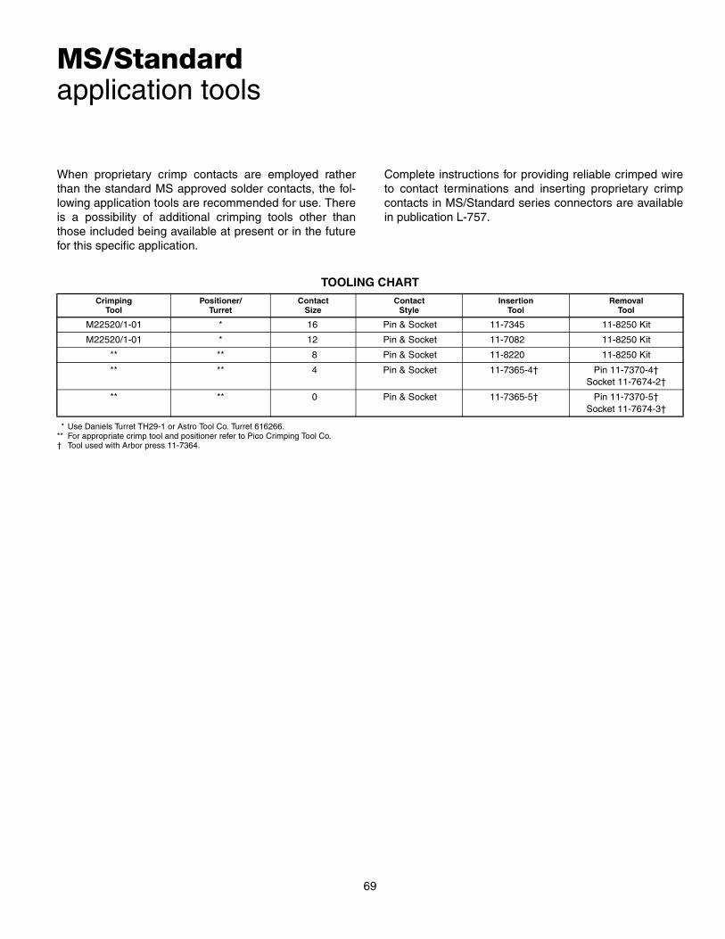
MS/Standardapplication tools
When proprietary crimp contacts are employed ratherthan the standard MS approved solder contacts, the fol-lowing application tools are recommended for use. Thereis a possibility of additional crimping tools other thanthose included being available at present or in the futurefor this specific application.
69
Complete instructions for providing reliable crimped wireto contact terminations and inserting proprietary crimpcontacts in MS/Standard series connectors are availablein publication L-757.
* Use Daniels Turret TH29-1 or Astro Tool Co. Turret 616266.** For appropriate crimp tool and positioner refer to Pico Crimping Tool Co.† Tool used with Arbor press 11-7364.
TOOLING CHARTCrimping
ToolPositioner/
TurretContact
SizeContact
StyleInsertion
ToolRemoval
Tool
M22520/1-01 * 16 Pin & Socket 11-7345 11-8250 Kit
M22520/1-01 * 12 Pin & Socket 11-7082 11-8250 Kit
** ** 8 Pin & Socket 11-8220 11-8250 Kit
** ** 4 Pin & Socket 11-7365-4† Pin 11-7370-4†Socket 11-7674-2†
** ** 0 Pin & Socket 11-7365-5† Pin 11-7370-5†Socket 11-7674-3†

MS/Standardhow to order
MIL-C-5015 (Solder Contacts)
MS 3102 A 18 – 3 P W (SR)1 2 3 4 5 6 7 8
1. Connector TypeMS designates Military StandardCS* designates service class A and C with proprietary
special contact arrangementsSG* designates service class E with proprietary special
contact arrangementsSM* designates service class F and R with proprietary
special contact arrangements2. Connector Style
3100 wall mounting receptacle3101 cable connecting plug3102 box mounting receptacle3106 straight plug3108 90° plug
3. Service ClassA solid shell for general, non-environmental applicationsC solid shell for pressurized applicationsE environmental resistingF environmental resisting with strain relief (MS part num-
ber only)R lightweight environmental resisting
4., 5.Shell size and insert arrangement - see tables, pages22–24.
6. Contact TypesP designates pin contactS designates socket contact
7. Insert Rotation“W”, “X”, “Y”, or “Z” designate that insert is rotated in its shell from normal position. No letter required for normal (no rotation) position.
8. (SR) strain relief for non-military connectors (For MS use “F” class)
* For insert arrangements over 50 and shell size 40 and above.Exceptions: 36-52, 40-1, 40-9 and 40-56 are MS approved.
Consult Amphenol, Sidney, NY for availability of alternate finishes, including black and olive drab zinc alloys.
70
Proprietary (Crimp Contacts)
75 – 68 0 12 – 3 H1 2 3 4 5 6
1. Connector Type75 – connector utilizing silver plated contacts80 – less contacts85 – contacts utilizing 50 micro-inches gold over silver
plating2. Service Class
68 service class A, general duty474 service class F, environmental resisting190 service class R, lightweight environmental resisting
3. Connector Style0 wall mounting receptacle1 cable connecting plug2 box mounting receptacle6 straight plug8 90° plug
4. Shell Size Designator
5. Insert ArrangementsSee page 22-24.
6. Contact Type/Alternate Insert RotationP designates pin, S designates socket for normal position-ing of inserts. When an alternate position of the connectorinsert is required to prevent cross-mating, a different letter(other than P or S) is used. See page 25 for description ofalternate positions, then convert to Amphenol® proprietarycoding by the following charts:
Shell Size 8S 10S 10SL 12S 12 14S 14 16S 16 18
Shell Designator 8 10 11 12 13 14 15 16 17 18
Shell Size 20 22 24 28 32 36 40 44 48
Shell Designator 20 22 24 28 32 36 40 44 48
Pin Contacts Socket Contacts
MS LetterAmphenol
LetterMS Letter
Amphenol
Letter
PW G SW H
PX I SX J
PY K SY L
PZ M SZ N

71
Additional MS/Standard Connectorsoffered by Amphenol
Amphenol®/Matrix® MS/Standard MIL-C-5015Connectors with Crimp Rear Relase Contacts
MS/Standard MIL-C-5015 Connectors with Crimp Rear Release ContactsAmphenol broadens their MS/Standard family of connectors with the addi-tion of the Matrix® MIL-C-5015 crimp rear release series. This seriesbridges the gap between the old connector standard and the environmentaland high performance needs of current technologies.
Design characteristics of the Amphenol/Matrix 5015 series include:• MS345( ) series intermateable with existing MIL-C-5015 solder
or crimp versions on existing equipment• Captive coupling nut mechanism, utilizes retaining rings in combination
with “L” washers to prevent inadvertent disassembly• Multiple interlock systems ensure permanent insert retention• Positive control of dielectric separation with guaranteed ease of
contact insertion• Positive contact retention provided by a closely toleranced damage-proof
metal retention clip• Completely sealed against environmental extremes with individual con-
tact seals, interfacial seals between contacts, peripheral gasket shell-to-shell seals and rear wire seals
Customer Options• Seven mounting styles, in shell sizes 8 to 48 (consult Amphenol for availability of shell sizes 44 and 48)• Threaded coupling or self-locking plug (MS3459) with an internal racheting mechanism to prevent
unmating due to vibration and shock, eliminating the need for safety wiring• Proprietary quick disconnect plug, with or without lanyard available• Classes include aluminum or stainless steel shells, or firewall capability• MS and Proprietary versions available• Some styles are supplied to McDonnell Douglas Specification BAN 7025, DC60 Series• Accommodation of contact sizes 0 to 16• Over 100 insert arrangement patterns available, accommodating from 1 to a maximum of 85 circuits• Alternate positioning available; thermocouple contacts available
Ask for Amphenol catalog 12-026 for detailed information.
MIL-C-5015 ModificationsIn order to supplement standard MS shell styles and provide a greater variety of styles for the electrical connectoruser, there are several MS and MS Modified cylindrical connectors offered by Amphenol.
These types include flange mount plugs, thru bulkhead receptacles, jam nut receptacles, connectors for potting andconnectors designed specifically to terminate jacketed cable.
Ask for Amphenol catalog 12-021 for detailed information.
97 Series, MIL-C-5015 Type ConnectorsThe low cost, general duty connector used extensively in the machine toolindustry, welding industry and numerous other industrial applications, is theAmphenol® 97 Series. Offered in non-environmental styles, these connec-tors have hard dielectric inserts and threaded coupling. They are Underwrit-ers Laboratories Recognized and Canadian Standards AssociationCertified.
Recent addition to this family is the 97E environmental styles, still an eco-nomical choice. The 97E can be used in a variety of industrial applicationswhere environmental sealing is required, such as automotive and robotics.
Ask for Amphenol catalog 12-022 for detailed information.
97 Series, MIL-C-5015 Type Connectors