amphenol heavy duty cylindrical connectors · mated ten complete 24 hour cycles of +25°c to +65°c...
TRANSCRIPT
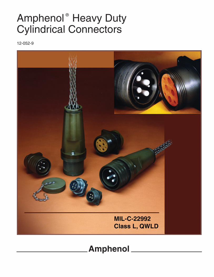
Amphenol Heavy DutyCylindrical Connectors12-052-9
®
Amphenol

1
• High Current Capacity• Rugged Construction• Safety• ServiceabilityAmphenol meets the demands for heavy duty connectors byproviding three cylindrical connector series, each with uniquedesign characteristics for reliable operation in specific indus-trial environments.Class “L” – for the heaviest electrical loads (Pages 2 – 19)• Current range from 40 to 200 amperes• Direct current or single/three phase, 60/400 Hertz alternat-
ing current• Automatic grounding for safety• MIL-C-22992 qualificationQWLD – for most power and control circuits (Pages 21 – 77)• Military (MIL-C-22992) qualified connectors and industrial
equivalents available• Increased shell size for greater durability than similar stan-
dard connectorsQWL – a more compact heavy duty design for industrial power and control applications
(Page 78, references Amphenol Catalog 12-053)These three series share the following common characteristics which are critical to reliable heavyduty connectors:• Resistance to the operating environment. Refer to environmental data, below.• Double stub coupling threads for faster connections; no cross threading, easy cleaning.• Left hand accessory threads to minimize cable twisting, wire breakage, accidental connector
disassembly.• Gaskets or O-rings at appropriate surfaces for perfect weathertight connections.Amphenol® heavy duty connectors have been exposed to the following environmental conditions,without compromise of mechanical integrity or degradation of electrical performance.
Condition Configuration Description Reference
Thermal Shock UnmatedFive complete one hour temperature cycles of–55°C to +125°C
MIL-STD-1344, method1003, test condition A
Moisture Resistance(Cable mounted connectors)
MatedTen complete 24 hour cycles of +25°C to+65°C temperature at 90% to 98% humidity
MIL-STD-202, method 106
Durability Mated 500 complete mating/unmating cycles MIL-C-22992
Salt Spray(Corrosion)
Unmated48 hour exposure to atomized 5%saline solution at +35°C
MIL-STD-1344,method 1001
Vibration Mated10 to 55 Hz, .06 inch total excursionin 1 minute cycles for 6 hours, 55 to2000 Hz, 10G peak amplitude sweep
MIL-STD-1344,method 2005
High Impact MatedNine hammer blows from 1, 3 and 5 feet,three each in three axes on mounting panel
MIL-STD-202,method 207
Heat Rise (Class L only) MatedMaximum rated DC current for fourhours at +25°C in still air
MIL-C-22992
Fluid Immersion Unmated20 hours immersion in hydraulicfluid and lubricating oil
MIL-C-22992
Water ImmersionMated andUnmated
4 hours immersion at 1 atmospherepressure differential
MIL-C-22992
Amphenol Heavy DutyCylindrical ConnectorsMIL-C-22992/Proprietary
®

2
Amphenol Heavy DutyCylindrical ConnectorsMIL-C-22992, Class L
wall mount receptacle (power source)
straight plug
cable connecting receptacle withoutcoupling ring
wall mount plug withcoupling ring (equipment end)
The Amphenol® Class L* heavyduty connectors are the largestsize cylindricals, highly suitable forindustrial or military applications,and designed to meet the demandsof heavy power interconnections.
The design features of this connec-tor series provide:
• Greatest Capacity -current ranges 40 to 200 amps, conductor sizes 6 to 4/0
• Safety -complete protection of personnel and equipment if connectors are inadvertently disconnected under load
• Foolproof Mating -design incorporates specific volt-age, current, frequency, phase and grounding requirements
• Standardization -MIL-C-22992 Class L insert arrangements specify connector/cable combinations for maximum reliability
• Serviceable Contacts -contacts are normally crimped to the cable before connector assem-bly. No insertion tools required. Bushings are available to adapt smaller diameter wires to larger contacts
* Amphenol design is covered by one or more of the following U. S. Patent Numbers: 3,023,396; 3,221,292.
®
3
Amphenol Heavy DutyCylindrical ConnectorsMIL-C-22992, Class L
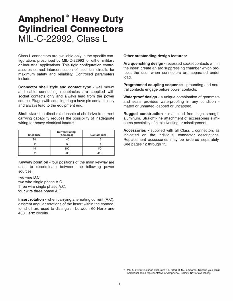
Class L connectors are available only in the specific con-figurations prescribed by MIL-C-22992 for either militaryor industrial applications. This rigid configuration controlassures correct interconnection of electrical circuits formaximum safety and reliability. Controlled parametersinclude:
Connector shell style and contact type - wall mountand cable connecting receptacles are supplied withsocket contacts only and always lead from the powersource. Plugs (with coupling rings) have pin contacts onlyand always lead to the equipment end.
Shell size - the direct relationship of shell size to currentcarrying capability reduces the possibility of inadequatewiring for heavy electrical loads.†
Keyway position - four positions of the main keyway areused to discriminate between the following powersources:
two wire D.Ctwo wire single phase A.C.three wire single phase A.C.four wire three phase A.C.
Insert rotation - when carrying alternating current (A.C),different angular rotations of the insert within the connec-tor shell are used to distinguish between 60 Hertz and400 Hertz circuits.
Shell SizeCurrent Rating
(Amperes) Contact Size
28 40 6
32 60 4
44 100 1/0
52 200 4/0
Other outstanding design features:
Arc quenching design - recessed socket contacts withinthe insert create an arc suppressing chamber which pro-tects the user when connectors are separated underload.
Programmed coupling sequence - grounding and neu-tral contacts engage before power contacts.
Waterproof design - a unique combination of grommetsand seals provides waterproofing in any condition -mated or unmated, capped or uncapped.
Rugged construction - machined from high strengthaluminum. Straight-line attachment of accessories elimi-nates possibility of cable twisting or misalignment.
Accessories - supplied with all Class L connectors asindicated on the individual connector descriptions.Replacement accessories may be ordered separately.See pages 12 through 15.
† MIL-C-22992 includes shell size 48, rated at 150 amperes. Consult your localAmphenol sales representative or Amphenol, Sidney, NY for availability.
®

4
MIL-C-22992, Class Lhow to order
Connectors are supplied with removable contacts unassembled and applica-ble accessories as listed in the individual connector style descriptions,pages 8 through 11. Additional/replacement contacts or accessories may beordered by their MS designations.
Connectors are ordered by MS designation. To illustrate the ordering proce-dure, part number MS90555 C32412SY is shown as follows:
PART NUMBER
MS90555 C 32 4 12 S Y
1 2 3 4 5 6 7
1. MS Number -MS90555 designates wall mount receptacle (power source)MS90556 designates straight plugMS90557 designates cable connecting receptacle without coupling ringMS90558 designates wall mount plug with coupling ring (equipment end)
2. Shell Finish - C (conductive) for AC or N (nonconductive) for DC circuits.
Grounding Assemblies: Finish C
ShellSize
CurrentRatingAmps
Shell Master Key/Keyway Position
60Hz & 400Hz
1 Phase 3 Phase
2 Wire 3 Wire 3 Wire 4 Wire
120 VAC 240 VAC120/240
VAC450/480
VAC120/208
VAC240/416
VAC277/480
VAC
28 40 4 (120°) 5 (135°) 4 (120°) --- 4 (120°) 5 (135°) 6 (150°)
32 60 4 (120°) 5 (135°) 4 (120°) --- 4 (120°) 5 (135°) 6 (150°)
44 100 4 (120°) --- 4 (120°) 1 (60°) 4 (120°) 5 (135°) 6 (150°)
52 200 --- --- 4 (120°) --- 4 (120°) 5 (135°) 6 (150°)
3. Shell Size - related directly to current carrying capability.Size 28 - 40 amperesSize 32 - 60 amperesSize 44 - 100 amperesSize 52 - 200 amperes
4. Master Key/Keyway Position - N designates normal position. Positions1, 4, 5 and 6 of the master key/keyway prevent cross-mating of incompat-ible voltages. Refer to the adjacent illustration.
5. Insert Arrangement - determined by connector size (current carryingcapability) and cable configuration to be accommodated. Refer to pages 5& 6.
6. Contact Type - P for pin, S for socket. MS90555 and MS90557 are sup-plied with socket contacts only. MS90556 and MS90558 are supplied withpin contacts only.
7. Alternate Insert Rotation - used to prevent cross-mating of incompatiblefrequencies. Absence of a letter in this space indicates normal (0°) posi-tion of the insert. Refer to page 7.
Non-grounding Assemblies: Finish N
ShellSize
CurrentRatingAmps
Shell Master/KeyKeyway Position
DC
2 Wire
28 VDC
28 40 N (105°)
32 60 N (105°)
44 100 N (105°)
52 200 N (105°)
4
56
NNormal
1
MASTERKEYWAY
TYPICALSOCKETARRANGEMENT
15REF
front face of receptacle shown
Note that insert arrangement does notrotate with master key/keyway
MASTER KEY/KEYWAY POSITION
Amphenol Federal Vendor Identification FSCM77820

5
MIL-C-22992, Class Lcontact arrangements
Shell Size 28, 40 amp rating Cable:
Contacts:
28-12 IPCEA, type G, round, four #8 conductors
28-13CO-04 HDF, (4/6-4/12R) 1090per MIL-C-3432
Position SizePin
M39029/48Socket
M39029/49
A, B, C 6 -317 -329
N, G 6N -318 -32928-12, 28-13Three phase AC, 4 wire, grounding
Shell Size 32, 60 amp rating
32-04, 32-05Single phase AC, 2 wire, grounding
Cable:
Contacts:
32-04 IPCEA, type G, round, two #6 conductors
32-05CO-02 HDF, (2/4-2/8R) 1100per MIL-C-3432
Position SizePin
M39029/48Socket
M39029/49
A 4 -320 -331
N 4N -321 -331
G1, G2 6N -318 -329
Shell Size 32, 60 amp rating
32-12, 32-13Three phase AC, 4 wire, grounding
Cable:
Contacts:
32-12 IPCEA, type G, round, four #6 conductors
32-13CO-04 HDF, (4/4-4/12R) 1290per MIL-C-3432
Position SizePin
M39029/48Socket
M39029/49
A, B, C 4 -320 -331
N 4N -321 -331
G 6N -318 -329
Shell Size 44, 100 amp rating
44-02, 44-0328 Volts DC, 2 wire
Cable:
Contacts:
44-02 IPCEA, type W, round, two #2 conductors
44-03CO-02 HDF, (2/1) 1385per MIL-C-3432
Position SizePin
M39029/48Socket
M39029/49
A 1/0-1 -323 -333
N 1/0N-1 -324 -333
CONTACT LEGEND 6 4 1/0 4/0
IPCEA – Insulated Power Cable Engineers Association
A N
C B
G
G1
N A
G2
C
A N
B
G
A
N

6
MIL-C-22992, Class Lcontact arrangements
Shell Size 44, 100 amp rating
44-12, 44-13Three phase AC, 4 wire, grounding
Cable:
Contacts:
44-12 IPCEA, type G, round, four #2 conductors
44-13CO-04 HDF, (4/1-4/8R) 1620per MIL-C-3432
Position SizePin
M39029/48Socket
M39029/49
A, B, C 1/0-1 -323 -333
N 1/0N-1 -324 -333
G1, G2, G3, G4 6G -319 -330
Shell Size 44, 100 amp ratingFor Navy Ground Support Equipment use only.
44-50, 44-51, 44-52, 44-56Three phase AC, 3 wire, grounding
Cable:
Contacts:
44-50Available in MS90555 & MS90558 only4 each # 1 conductors
44-51Available in MS90556 & MS90557 onlyIPCEA, type W, round, four # 1 conductors
44-52Available in MS90556 onlyIPCEA, type W, round, four # 2 conductors
44-56Available in MS90556 onlyIPCEA, type W, round, four # 6 conductors
Position SizePin
M39029/48Socket
M39029/49
A, B, C 1/0-1 -323 -333
G 1/0N-1 -324 -333
Shell Size 52, 200 amp rating
52-12, 52-13Three phase AC, 4 wire, grounding
Cable:
Contacts:
52-12 IPCEA, type G, round, four #4/0 conductors
52-13CO-04 HDE, (4/0000-4/4R) 2380per MIL-C-3432
Position SizePin
M39029/48Socket
M39029/49
A, B, C 4/0 -327 -335
N 4/0N -328 -335
G1, G2, G3, G4 4G -322 -332
IPCEA – Insulated Power Cable Engineers Association
A
G4 G1
G3 G2
B
C N
A
G B
C
A
B
G4 G1
C N
G3 G2
CONTACT LEGEND 6 4 1/0 4/0

7
MIL-C-22992, Class Lalternate insert rotations
To avoid cross-plugging problems in applications requiringthe use of more than one connector of the same size andarrangement, alternate insert rotations are available asindicated in the accompanying chart.
As shown in the diagram below, the front face of the pininsert is rotated within the shell in a clockwise directionfrom the normal shell key. The socket insert would berotated counterclockwise the same number of degrees inrespect to the normal shell key.
Views looking into front face of pin insert or rear of socket insert.
InsertArrangements
Keying Position(degrees from normal position)
DC or 60 HzNormal
400 Hz
W X Y Z
28-12 0 – – 180 –
28-13 0 – – 180 –
32-04 0 – 90 – –
32-05 0 – 90 – –
32-12 0 – – 180 –
32-13 0 – – 180 –
44-12 0 – – – 60
44-13 0 – – – 60
44-50 0 – – – –
44-51 0 – – – –
44-52 0 – – – –
44-56 0 – – – –
52-12 0 300 – – –
52-13 0 300 – – –
B
A
A B A
B
A
B
Position W Position X Position Y Position Z

8
J
.531MINFULLTHD
F*
G N
GROMMETGASKET
H
A
T4 HOLES
S
R.312
+.011–.010
.750 +.031–.000
.031±.005
MIL-C-22992, Class LMS90555wall mount receptacle (power source)
All dimensions for reference only.
To complete MS Part number see how to order, pg. 4.Protective cover MS90563 is supplied as part of this connector assembly. Refer to page 15 for dimensions.*F dimension applies only when rear nut is fully tightened
ShellSize
A ThreadClass 2A
.1428P-.2857LDouble Stub
F*±.031
GDia.
+.006–.010
H±.005
J+.016–.000
NDia.
+.011–.020
R(BSC)
S+.021–.020
TDia.
±.005
28 2.000 1.376 1.938 1.514 2.188 2.000 1.844 2.375 .177
32 2.250 1.376 2.188 1.514 2.188 2.250 2.062 2.625 .209
44 3.000 1.438 3.062 1.733 2.532 3.125 2.812 3.375 .281
52 3.500 1.438 3.562 1.733 2.532 3.625 3.156 3.875 .281

9
M L
"O" RING
K
MAIN JOINTGASKET
C
Q
GLAND
.750 +.031–.000
N E
A
MIL-C-22992, Class LMS90556straight plug
All dimensions for reference only.
ShellSizeand
Arrangement
A ThreadClass 2B
.1428P-.2857LDouble Stub
CDia.Max
ECableRange
K±.005
LMaxFree
Length
MApprox.
FreeLength
NDia
+.011–.020
QDia.Max
28-122.000 2.439
1.047-.9221.557 8.188
7.1882.000 2.312
28-13 1.130-1.005 7.188
32-04
2.250 2.689
.969-.844
1.557 8.188
7.188
2.000 2.56232-05, -12 1.130-1.005 7.188
32-13 1.342-1.217 8.688
44-02
3.000 3.667
1.312-1.187
1.776 10.172
10.688
2.500 3.53144-03 1.438-1.313 9.688
44-12 1.516-1.391 10.688
44-13 1.672-1.547 12.688
44-51
3.000 3.667
1.734-1.609
1.776 10.172
11.688
2.500 3.53144-52 1.525-1.435 11.188
44-56 1.135-1.065 7.188
52-123.500 4.167
2.328-2.1831.776 11.109
17.1883.250 4.016
52-13 2.453-2.308 18.188
To complete MS Part number see how to order, pg. 4.Protective cover MS90564 is supplied as part of this connector assembly. Refer to page 15 for dimensions. Contact brushings MS3348 are supplied as part of connector as required. Refer to page 13 for dimensions.

10
MIL-C-22992, Class LMS90557cable connecting receptacle without coupling ring
All dimensions for reference only.
To complete MS Part number see how to order, pg. 4.Protective cover MS90563 is supplied as part of this connector assembly. Refer to page 15 for dimensions.Contact bushings MS3348 are supplied as part of connector as required. Refer to page 13 for dimensions.
ShellSizeand
Arrangement
A ThreadClass 2A
.1428P-.2857LDouble Stub
B±.005
CDia.Max.
ECableRange
LMaxFree
Length
MApprox.
Free Length
NDia
+.011–.020
28-122.000 1.514 2.439
1.047-.9228.156
7.1882.000
28-13 1.130-1.005 7.188
32-04
2.250 1.514 2.689
.969-.844
8.156
7.188
2.00032-05, -12 1.130-1.005 7.188
32-13 1.342-1.217 8.688
44-02
3.000 1.733 3.667
1.312-1.187
10.125
10.688
2.500
44-03 1.438-1.313 9.688
44-12 1.516-1.391 10.688
44-13 1.672-1.547 12.688
44-51 1.734-1.609 11.688
52-123.500 1.733 4.167
2.328-2.18311.062
17.1883.250
52-13 2.453-2.308 18.188
LC M
NE
GLAND"O" RING
.750 +.031–.000
B
A
.531MIN FULL THD
11
J F
T4 HOLES
S
R
Q
INTERFACIALSEAL
MAIN JOINT GASKET
A
K
.750 +.031–.000
.312+.011–.010.031
±.005
GASKET
GROMMET
N G
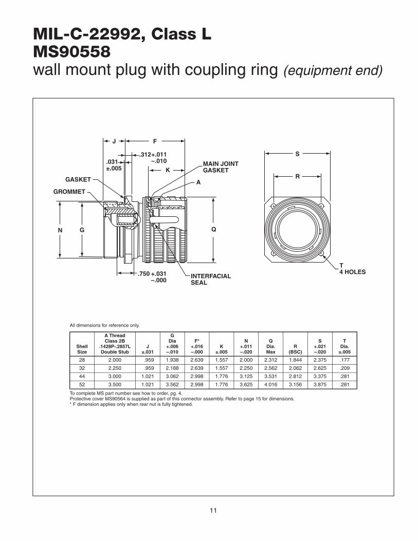
MIL-C-22992, Class LMS90558wall mount plug with coupling ring (equipment end)
To complete MS part number see how to order, pg. 4.Protective cover MS90564 is supplied as part of this connector assembly. Refer to page 15 for dimensions.* F dimension applies only when rear nut is fully tightened.
ShellSize
A ThreadClass 2B
.1428P-.2857LDouble Stub
J±.031
GDia
+.006–.010
F*+.016–.000
K±.005
N+.011–.020
QDia.Max
R(BSC)
S+.021–.020
TDia.
±.005
28 2.000 .959 1.938 2.639 1.557 2.000 2.312 1.844 2.375 .177
32 2.250 .959 2.188 2.639 1.557 2.250 2.562 2.062 2.625 .209
44 3.000 1.021 3.062 2.998 1.776 3.125 3.531 2.812 3.375 .281
52 3.500 1.021 3.562 2.998 1.776 3.625 4.016 3.156 3.875 .281
All dimensions for reference only.

12
AREF
B
CH
.750+.031–.000
G
D
KREF
.750+.031–.000
J
H C
G
MIL-C-22992, Class L Accessoriescontacts
All dimensions for reference only.
*Order by MS part number listed for either socket or pin.
SocketMS PartNumber*
PinMS PartNumber
ContactSize
WireWellSize
ARef.
B±.005
CDia
DDia
±.001G
DiaH
DiaJ
±.005K
Ref
M39029/49-335 M39029/48-327 4/0 4/0 3.207 2.097 .641+.004–.003
.500 .781 ± .003 .750+.004–.003
1.283 2.393
--- M39029/48-328 4/0N 4/0 3.325 2.215 .641+.004–.003
.500 .781 ± .003 .750+.004–.003
--- ---
M39029/49-333 M39029/48-323 1/0 1 3.207 2.097 .406+.004–.003
.357 .609 ± .003 .506+.004–.003
1.283 2.393
--- M39029/48-324 1/0N 1 3.325 2.215 .406+.004–.003
.357 .609 ± .003 .506+.004–.003
--- ---
M39029/49-331 M39029/48-320 4 4 2.786 1.738 .281 ±.002 .225 .417 ± .002 .374 ± .002 1.158 2.206
--- M39029/48-321 4N 4 2.904 1.856 .281 ±.002 .225 .417 ± .002 .374 ± .002 --- ---
M39029/49-329 M39029/48-317 6 6 2.786 1.738 .234 ±.002 .178 .342 ± .002 .312 ± .002 1/158 2.206
--- M39029/48-318 6N 6 2.904 1.856 .234 ±.002 .178 .342 ± .002 .312 ± .002 --- ---
M39029/49-332 M39029/48-322 4G 4 2.856 1.746 .281 ±.002 .225 .417 ± .002 .374 ± .002 1.752 2.862
M39029/49-330 M39029/48-319 6G 6 2.856 1.746 .234 ±.002 .178 .342 ± .002 .312 ± .002 1.752 2.862
M39029/48pin contact
M39029/49socket contact

13
.700 +.017–.016
B A
A
2.500 ±.016
MIL-C-22992, Class L Accessoriescontact bushing/removal tool
MS3348contact bushing
All dimensions for reference only.
* Order by MS part number listed.
MS PartNumber*
ContactWire
Barrel Size(Ref)
WireSize(Ref)
ADia
+.010–.003
BDia
+.002–.003
MS3348-1 - 2L 1 2 .359 .396
MS3348-4 - 5L 4 5 .250 .272
MS3348-4 - 6L 4 6 .225 .272
MS3348-6 - 8L 6 8 .185 .225
MS3348-6 - 9L 6 9 .155 .225
MS3348-1 - 6L 1 6 .225 .396
MS3348-4 - 8L 4 8 .185 .272
MS3348-6 -10L 6 10 .136 .225
MS3348-4/0-2/0L 4/0 2/0 .500 .629
MS90562contact removal tool
All dimensions for reference only.
* Order by MS part number listed.
MS PartNumber*
ContactSize
ADia
+.000–.002
MS90562-1 4/0 .790
MS90562-2 2/0 .696
MS90562-3 1/0 .558
MS90562-4 2 .462
MS90562-5 4 .376
MS90562-6 6 .354
14
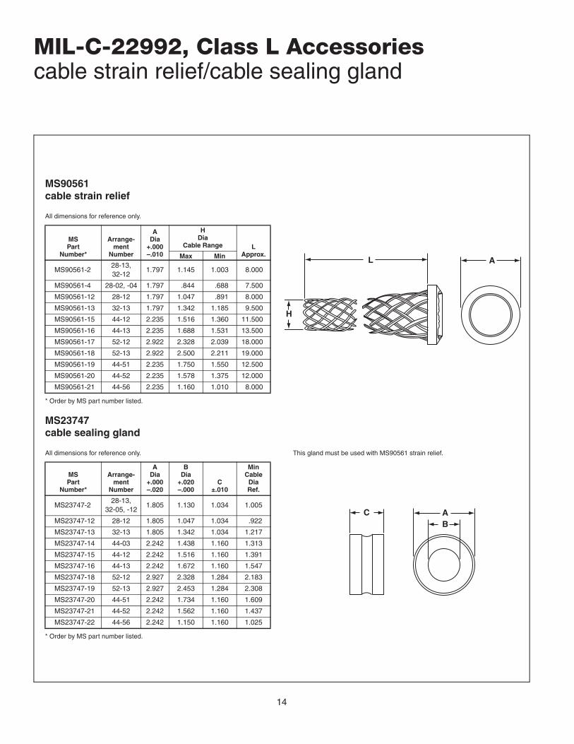
MIL-C-22992, Class L Accessoriescable strain relief/cable sealing gland
MS90561cable strain relief
All dimensions for reference only.
* Order by MS part number listed.
MSPart
Number*
Arrange-ment
Number
ADia
+.000–.010
HDia
Cable Range LApprox.Max Min
MS90561-228-13,32-12
1.797 1.145 1.003 8.000
MS90561-4 28-02, -04 1.797 .844 .688 7.500
MS90561-12 28-12 1.797 1.047 .891 8.000
MS90561-13 32-13 1.797 1.342 1.185 9.500
MS90561-15 44-12 2.235 1.516 1.360 11.500
MS90561-16 44-13 2.235 1.688 1.531 13.500
MS90561-17 52-12 2.922 2.328 2.039 18.000
MS90561-18 52-13 2.922 2.500 2.211 19.000
MS90561-19 44-51 2.235 1.750 1.550 12.500
MS90561-20 44-52 2.235 1.578 1.375 12.000
MS90561-21 44-56 2.235 1.160 1.010 8.000
MS23747cable sealing gland
All dimensions for reference only. This gland must be used with MS90561 strain relief.
* Order by MS part number listed.
MSPart
Number*
Arrange-ment
Number
ADia
+.000–.020
BDia
+.020–.000
C±.010
MinCable
DiaRef.
MS23747-228-13,
32-05, -121.805 1.130 1.034 1.005
MS23747-12 28-12 1.805 1.047 1.034 .922
MS23747-13 32-13 1.805 1.342 1.034 1.217
MS23747-14 44-03 2.242 1.438 1.160 1.313
MS23747-15 44-12 2.242 1.516 1.160 1.391
MS23747-16 44-13 2.242 1.672 1.160 1.547
MS23747-18 52-12 2.927 2.328 1.284 2.183
MS23747-19 52-13 2.927 2.453 1.284 2.308
MS23747-20 44-51 2.242 1.734 1.160 1.609
MS23747-21 44-52 2.242 1.562 1.160 1.437
MS23747-22 44-56 2.242 1.150 1.160 1.025
H
L A
C AB

15
MIL-C-22992, Class L Accessoriesprotective covers
MS90563 protective coversused with: MS90555 wall mount receptacle
MS90557 cable connecting receptacleAll dimensions for reference only.
* To complete MS part number, add letter C (Conductive) for AC or N(Non-conductive) for DC connector assemblies.
MSPart
Number*
UsewithShellSize
A ThreadClass 2B
.1428P-.2857LDouble Stub
B DiaRef
CApprox.
ForMS90555
ForMS90557
MS90563-1( ) 28 2.000 .177 .177 6.000
MS90563-3( ) 32 2.250 .209 – 4.500
MS90563-4( ) 32 2.250 – .177 6.000
MS90563-7( ) 44 3.000 .281 .281 7.500
MS90563-11( ) 52 3.500 .281 .281 7.500
MS90564 protective coversused with: MS90556 straight plug
MS90558 wall mount plugAll dimensions for reference only.
* To complete MS part number, add letter C (Conductive) for AC or N(Non-conductive) for DC connector assemblies.
MS PartNumber*
UsewithShellSize
A ThreadClass 2A (Plated)
.1428P-.2857LDouble Stub
B DiaRef
CApprox.
JMax
ForMS90556
ForMS90558
MS90564-1( ) 28 2.000 .177 .177 7.500 2.266
MS90564-3( ) 32 2.250 – .209 6.000 2.266
MS90564-4( ) 32 2.250 .177 – 7.500 2.266
MS90564-7( ) 44 3.000 .281 .281 8.500 2.484
MS90564-11( ) 52 3.500 .281 .281 8.500 2.484
A
GASKET
.969MAX
C
B
J
A
RIVET
C
B

16
MIL-C-22992, Class Linstallation instructions
Complete installation instructions (L-1014) for Class L connectors are available onrequest. Reproduced below are condensed assembly instructions to familiarize theuser with the installation procedure and tooling required.
Cable Preparation (MS90556 and MS90557 connectors only)The following table shows the standard wire color coding, generator terminal mark-ings, and connector contact identification used with Class L connectors.
Standardized Generator Wiring and Connections
Step 1) Determine cable lay to facilitate alignment of contacts and insert holeswithout wire crossing.
Step 2) Strip cable jacket to dimension shown. Avoid cutting or nicking individualconductor insulation.
GeneratorTerminal Marking Current
ContactDesignation
ConductorCircuit Wire Color
+ (POS)– (NEG) ground
28Vdc28Vdc
AN
PositiveNegative
BlackWhite
L1L2L3L0G (or Gnd)
ACACACACAC
ABCNG
Phase APhase BPhase CNeutral
Safety grounding
BlackRedBlue (Commercial may be orange)WhiteGreen (Commercial may be bare)
ConnectorSize
DInches
Approx.
28 3.000
32 3.000
44 4.250
52 5.000
Note
Some insert arrangements require that two or more ground wires be termi-nated into one contact. Dimension D must therefore be increased to permit routing these wires around the larger conductors.
Step 3) Install connector components in the order shown in the applicable assem-bly view illustrated on pages17 and 18.
Step 4) Strip insulation of individual conductors to 3/4 inch from end of conductor.
D SEENOTE
OUTERJACKET

17
2 1
5 4 3
MS90555 Connector
MS90556 Connector
MIL-C-22992, Class Linstallation instructions
Wall Mount Receptacle Components:1. Shell2. Insert Assembly, Socket3. Contact, Socket4. Grommet Assembly, Socket5. Nut, Retaining6. Protective Cap Assembly (Not Shown)7. Flange Gasket (Not Shown)
Straight Plug Components:1. Shell and Coupling Nut Assembly2. Insert Assembly, Pin3. Contact, Pin4. Spacer Assembly, Pin5. Back Adapter6. Gland Washer7. Gland8. Cable Grip9. Gland Nut
10. Lockwasher (3 each)11. Screw (3 each)12. Protective Cap Assembly (Not Shown)
Note: On shell size 32 connectors, item #6 (Gland Washer) is contained within item #5 (Back Adaper).
18
2
5 4 3 1
9 8 7 6 5
11 10
4 3 2 1
MIL-C-22992, Class Linstallation instructions
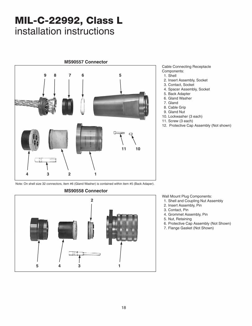
Cable Connecting ReceptacleComponents:1. Shell2. Insert Assembly, Socket3. Contact, Socket4. Spacer Assembly, Socket5. Back Adapter6. Gland Washer7. Gland8. Cable Grip9. Gland Nut
10. Lockwasher (3 each)11. Screw (3 each)12. Protective Cap Assembly (Not shown)
Wall Mount Plug Components:1. Shell and Coupling Nut Assembly2. Insert Assembly, Pin3. Contact, Pin4. Grommet Assembly, Pin5. Nut, Retaining6. Protective Cap Assembly (Not Shown)7. Flange Gasket (Not Shown)
Note: On shell size 32 connectors, item #6 (Gland Washer) is contained within item #5 (Back Adaper).
MS90557 Connector
MS90558 Connector

19
MIL-C-22992, Class Linstallation instructions
Contact Installation
Step 1) Insert stripped conductors in contact wirewells.If contact bushing is used, insert conductor in bushingand bushing in contact wirewell. If two or more groundwires are inserted into a single contact, make sure allwires are fully seated in wirewell.
Step 2) Select correct crimping tool, locater and diecombination from the table for contacts to be installed.With conductor or contact bushing in place, insert contactinto tool. Close crimping die fully to form a uniform crimp.
* Available from Pico Crimping Tools Co.,9832 Jersey Ave.Santa Fe Springs, CA 90670Phone: 805-388-5510
If crimping tools are available, contacts may be affixed toconductors by soldering. Use rosin-alcohol solder flux, agood grade of 60/40 solder and a 500 watt soldering ironor probe type resistance soldering equipment. Pre-tinconductors before soldering. Solder must not be presenton shoulder or retention area of contact.
ContactPart
NumberSize Type Crimping
Tool* Locator* Die* RemovalTool
M39029/48-327M39029/49-335M39029/48-328
4/04/0
4/0N
PSP
Pico Model400B or400B-1
4297-1 414DA-4/0N-1 MS90562-1
M39029/48-323M39029/49-333M39029/48-324
1/01/0
1/0N
PSP
Pico Model400B or400B-1
4297-3 414DA-1/0N MS90562-3
M39029/48-320M39029/49-331M39029/48-321M39029/48-322M39029/49-332
44
4N4G4G
PSPPS
Pico Model400B or400B-1
4297-5 414DA-4N MS90562-5
M39029/48-317M39029/49-329M39029/48-318M39029/48-319M39029/49-330
66
6N6G6G
PSPPS
Pico Model400B or400B-1
4297-6 414DA-6N MS90562-6
Connector Assembly
Step 1) If inserts are not already positioned in the con-nector shell, align large tab on insert with large slot inshell and push insert in until it bottoms in shell.
Step 2) Apply a thin coating of Dow Corning DC-4 lubri-cant to the periphery of contact holes in spacer or grom-met assembly. Push contacts into rear of spacer orgrommet assembly until locked into contact retainerbushing.
Step 3) Align contacts with proper holes in insert. Smallkey of insert must be aligned with appropriate keyway inspacer or grommet assembly. Slide contacts into insertholes until spacer or grommet assembly butts againstinsert. A thin film of Dow Corning DC-4 lubricant appliedto the periphery of insert contact holes will provide maxi-mum sealing efficiency.
Step 4) Assemble accessories to connector. The backadapter “O” ring should have a very thin film of DowCorning DC-4 lubricant applied. Outer surfaces only ofgland should be lubricated with a thin film of UniTempGrease EP. Avoid getting grease on inside surfaces ofgland and on cable jacket.
Step 5) Tighten retaining nut or gland nut on shell oradapter. A metal-to-metal seating condition is desireable,but may not be attainable with maximum cable diameters.
Contact Removal
Step 1) Loosen all rear accessories and slide back alongcable.
Step 2) Remove spacer or grommet assembly with con-tacts from connector insert.
Step 3) Using the appropriate size contact removal tool,push tool over front of contact until it bottoms in spacer orgrommet assembly hole. This will open contact retainingbushing and allow contact to be removed from the spaceror grommet assembly from the rear. When using jacketedcable, all contacts should be released from contact reten-tion bushings before removal from spacer or grommetassembly is accomplished.