„motion“homepages.laas.fr/nic/movie/workshop/slides/lothar.teske.pdflothar teske / toulouse /...
TRANSCRIPT
„MOTION“IN VIRTUAL DEVELOPMENT
PROCESS
Lothar TeskeToulouse / 07.01.2005

Lothar Teske / Toulouse / 07.01.2005 / 2
Product Development ProcessContents
1 Milestones
2 Development Partner
3 Network
4 Data Management
5 Synchronization Process
6 Development Tools
7 Summary

Lothar Teske / Toulouse / 07.01.2005 / 3
Future Targets in theVehicle Development Process
Mule Alpha Beta 1 Gamma Pilot
Simulation
Beta 2HW Phases
Virtual Phases
PastPast
EngineeringEngineeringStartStart
StylStyl. / Pack.. / Pack.FreezeFreeze
ReleaseRelease Start ofStart ofProductionProduction
ValidationValidationMuleMule
Integrated Virtual EngineeringStyl., Design, DMU, CAE, ME, Plants, ...Validation
EngineeringEngineeringStartStart
StylStyl. / Pack.. / Pack.FreezeFreeze
ReleaseRelease Start ofStart ofProductionProduction
Mission
Mission
HW PhasesStructure Integration Validation PilotMule
Initial ConceptStructure Integration ValidationTodayToday StylStyl. / Pack.. / Pack.
FreezeFreezeReleaseRelease Start ofStart of
ProductionProductionEngineeringEngineering
StartStart
44Fast to MarketFast to Market44Workload ReductionWorkload Reduction44Prototype ReductionPrototype Reduction
Lothar Teske / Toulouse / 07.01.2005 / 4
Milestones in the Development Process
EngineeringEngineeringStartStart
Styling / PackageStyling / PackageFreezeFreeze ReleaseRelease StartStart
ProductionProduction
ArchitectureIntegration
Design, Test
Validation
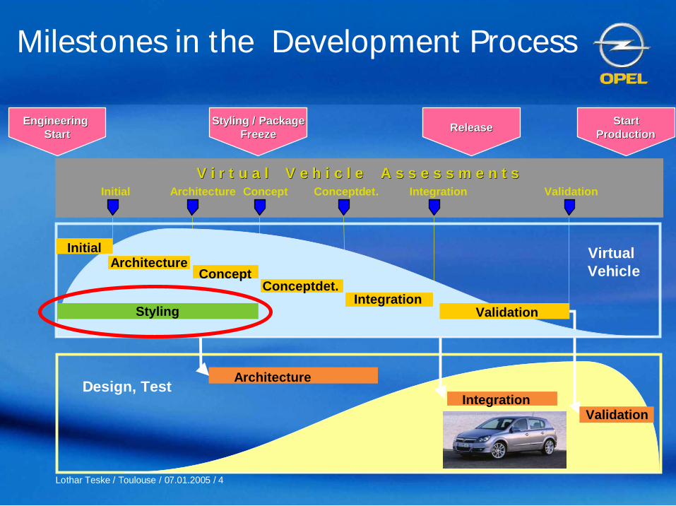
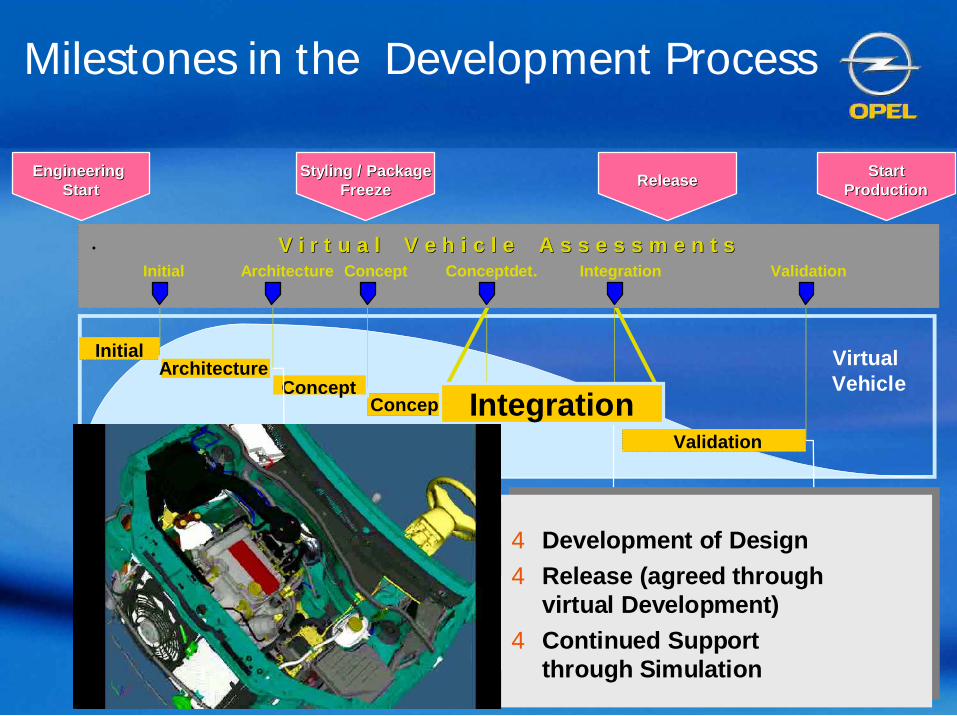
Initial Concept ValidationIntegrationConceptdet.ArchitectureV i r t u a l V e h i c l e A s s e s s m e n t sV i r t u a l V e h i c l e A s s e s s m e n t s
Initial
IntegrationConceptdet.
Validation
VirtualVehicle
Styling
ArchitectureConcept

Lothar Teske / Toulouse / 07.01.2005 / 5
Role of Design in theDevelopment Process
2
5
4 6
1 9
2 8
3 7Math
SurfaceRelease
12
3
Competition
of up to
3 Teams
Kickoff
AlternativeDevelopment Styling ConceptStyling Theme
Alternatives
VR supports Development in Clay
Lothar Teske / Toulouse / 07.01.2005 / 6
Architecture
ConceptInitial
IntegrationConceptdet.
Validation
VirtualVehicle
IntegrationDesign, Test
Validation
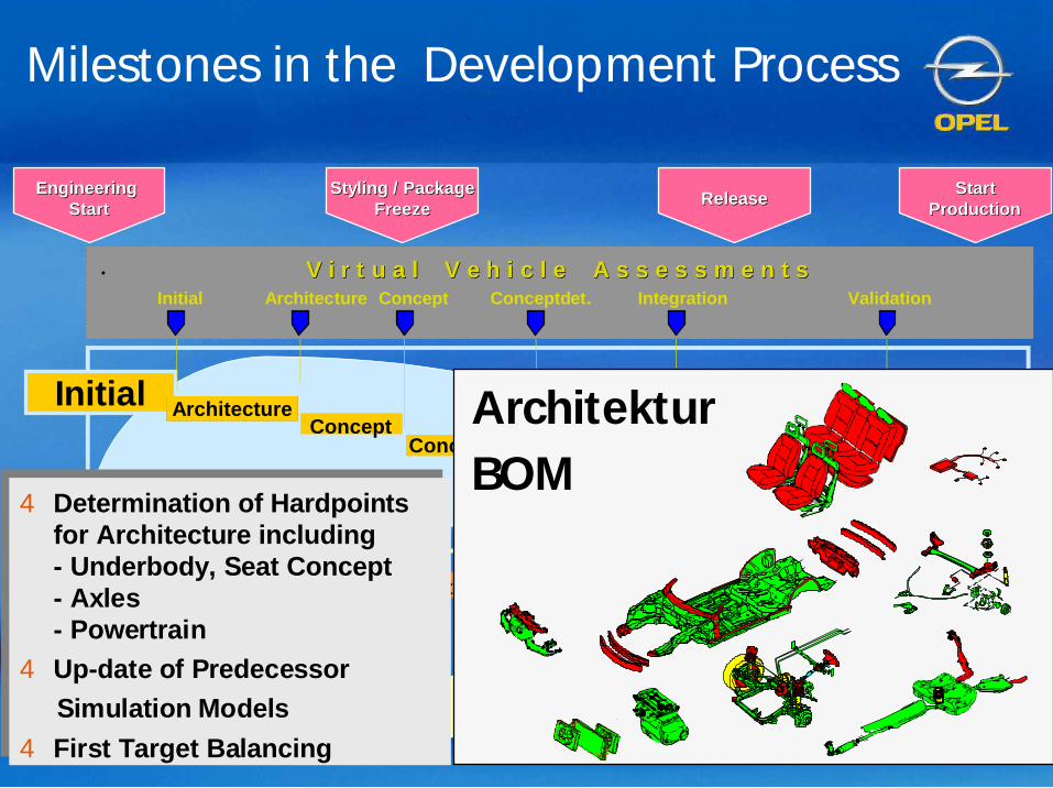
Architecture
4 Determination of Hardpointsfor Architecture including- Underbody, Seat Concept- Axles- Powertrain
4 Up-date of PredecessorSimulation Models
4 First Target Balancing
4 Determination of Hardpointsfor Architecture including- Underbody, Seat Concept- Axles- Powertrain
4 Up-date of PredecessorSimulation Models
4 First Target Balancing
Initial Concept ValidationIntegrationConceptdet.Architecture
EngineeringEngineeringStartStart
Styling / PackageStyling / PackageFreezeFreeze ReleaseRelease StartStart
ProductionProduction
V i r t u a l V e h i c l e A s s e s s m e n t sV i r t u a l V e h i c l e A s s e s s m e n t s
Milestones in the Development Process
ArchitekturBOM

Lothar Teske / Toulouse / 07.01.2005 / 7
Concept
Initial
IntegrationConceptdet.
Validierung
VirtualVehicleArchitecture
Initial Concept ValidationIntegrationConceptdet.Architecture
EngineeringEngineeringStartStart
Styling / PackageStyling / PackageFreezeFreeze ReleaseRelease StartStart
ProductionProduction
V i r t u a l V e h i c l e A s s e s s m e n t sV i r t u a l V e h i c l e A s s e s s m e n t s
Milestones in the Development Process
ArchitectureIntegration
Design, Test
Validation
4 Architecture Development4 Design and Release
of Mule Cars4 First Determination of
Hardpoints in Styling Studio
4 Architecture Development4 Design and Release
of Mule Cars4 First Determination of
Hardpoints in Styling Studio

Lothar Teske / Toulouse / 07.01.2005 / 8
InitialArchitecture
IntegrationConceptdet.
Validation
VirtualVehicleConcept
Initial Concept ValidationIntegrationConceptdet.Architecture
EngineeringEngineeringStartStart
Styling / PackageStyling / PackageFreezeFreeze ReleaseRelease StartStart
ProductionProduction
V i r t u a l V e h i c l e A s s e s s m e n t sV i r t u a l V e h i c l e A s s e s s m e n t s
Milestones in the Development Process
ArchitectureIntegration
Design, Test
Validation
4 Pre-Release of Styling4 Integration of Requirements from
Styling,Performance,Package,Manufacturing etc.
4 Pre-Release of Styling4 Integration of Requirements from
Styling,Performance,Package,Manufacturing etc.
Lothar Teske / Toulouse / 07.01.2005 / 9
Concept
InitialArchitecture
IntegrationValidation
VirtualVehicleConceptdetail
Initial Concept ValidationIntegrationConceptdet.Architecture
EngineeringEngineeringStartStart
Styling / PackageStyling / PackageFreezeFreeze ReleaseRelease StartStart
ProductionProduction
V i r t u a l V e h i c l e A s s e s s m e n t sV i r t u a l V e h i c l e A s s e s s m e n t s
Milestones in the Development Process
ArchitectureIntegration
Design, Test
Validation
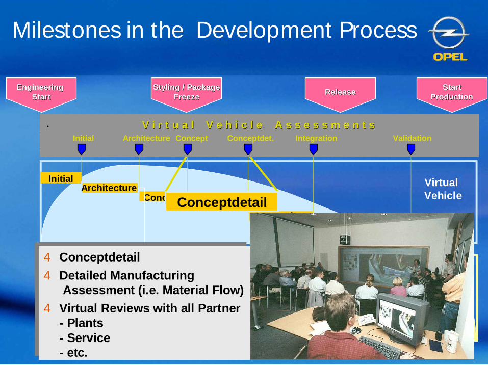
4 Conceptdetail4 Detailed Manufacturing
Assessment (i.e. Material Flow)4 Virtual Reviews with all Partner
- Plants- Service- etc.
4 Conceptdetail4 Detailed Manufacturing
Assessment (i.e. Material Flow)4 Virtual Reviews with all Partner
- Plants- Service- etc.
Lothar Teske / Toulouse / 07.01.2005 / 10
Concept
InitialArchitecture
Conceptdet.
Validation
VirtualVehicle
Integration
Initial Concept ValidationIntegrationConceptdet.Architecture
EngineeringEngineeringStartStart
Styling / PackageStyling / PackageFreezeFreeze ReleaseRelease StartStart
ProductionProduction
V i r t u a l V e h i c l e A s s e s s m e n t sV i r t u a l V e h i c l e A s s e s s m e n t s
Milestones in the Development Process
ArchitectureIntegration
Design, Test
Validation
4 Development of Design4 Release (agreed through
virtual Development)4 Continued Support
through Simulation
4 Development of Design4 Release (agreed through
virtual Development)4 Continued Support
through Simulation

Lothar Teske / Toulouse / 07.01.2005 / 11
Architektur
Konzept
InitialArchitektur
IntegrationKonzeptdet.
VirtualVehicle
IntegrationKonstruktion, Test
Validation
Validation
Initial Concept ValidationIntegrationConceptdet.Architecture
EngineeringEngineeringStartStart
Styling / PackageStyling / PackageFreezeFreeze ReleaseRelease StartStart
ProductionProduction
V i r t u a l V e h i c l e A s s e s s m e n t sV i r t u a l V e h i c l e A s s e s s m e n t s
4 Validation of Simulation Models4 Support for necessary late
Product-/Part Changes4 Virtual Plant
4 Validation of Simulation Models4 Support for necessary late
Product-/Part Changes4 Virtual Plant
Milestones in the Development Process

Lothar Teske / Toulouse / 07.01.2005 / 12
PlatformPE Body
PE Chassis
PE Thermal
Electric/Electronic
VehicleIntegration
VehicleSimulation
Noise &Vibration
SafetySupplier Eng.
Supplier
Test &Validation
ServiceEngineering
VehicleDevelopment
& Trim
MEAC
MEP
MEB
Plants
GM/ FIATPowertrain
Development Partner

Lothar Teske / Toulouse / 07.01.2005 / 13
Architecture CAD CAMStyling Dimensions DieVirtualFactoryCAE/CAT
Common Visualization Tool
ParasolidData Management (Product & Process)Data Management (Product & Process)
Service andProcess
Documentation
DesignReviews
ME Process-Simulation
SuppliersPurchasing
Finance
Visual ConceptReviews
GlobalDatabaseSystem
Data ManagementIntegrated Systems & Data Formats

Lothar Teske / Toulouse / 07.01.2005 / 14
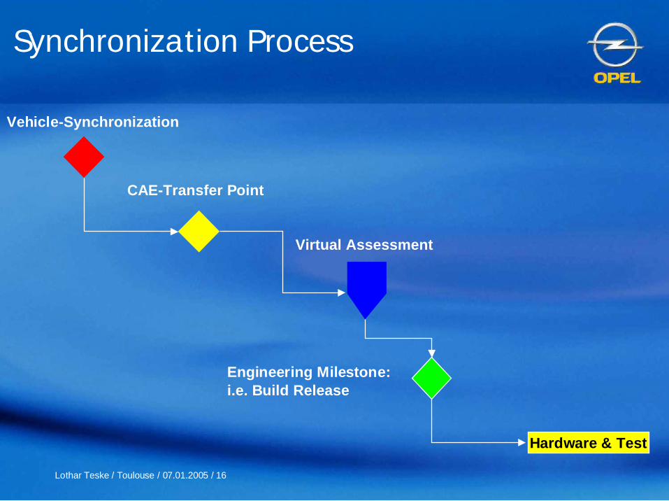
Synchronization Process
Engineering Milestone:i.e. Build Release
Virtual Assessment
Vehicle-Synchronization
Test
Initial Concept ValidationIntegrationConceptdet.Architecture
EngineeringEngineeringStartStart
Styling / PackageStyling / PackageFreezeFreeze ReleaseRelease StartStart
ProductionProduction
V i r t u a l V e h i c l e A s s e s s m e n t sV i r t u a l V e h i c l e A s s e s s m e n t s

Lothar Teske / Toulouse / 07.01.2005 / 15
Engineering Milestone:i.e. Build Release
Virtual Assessment
Vehicle-Synchronization
Hardware & Test Hardware & Test
Synchronization Process
Initial Concept ValidationIntegrationConceptdet.Architecture
EngineeringEngineeringStartStart
Styling / PackageStyling / PackageFreezeFreeze ReleaseRelease StartStart
ProductionProduction
V i r t u a l V e h i c l e A s s e s s m e n t sV i r t u a l V e h i c l e A s s e s s m e n t s
Lothar Teske / Toulouse / 07.01.2005 / 16
Engineering Milestone:i.e. Build Release
Vehicle-Synchronization
Virtual Assessment
CAE-Transfer Point
Hardware & Test
Synchronization Process
Lothar Teske / Toulouse / 07.01.2005 / 17
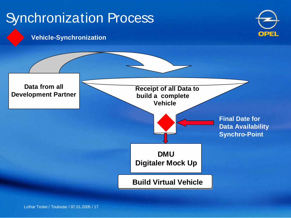
Vehicle-Synchronization
Receipt of all Data tobuild a complete
Vehicle
Build Virtual Vehicle
Data from allDevelopment Partner
Final Date forData AvailabilitySynchro-Point
DMUDigitaler Mock Up
Synchronization Process

Lothar Teske / Toulouse / 07.01.2005 / 18
Vehicle Synchronization
Synchronization Process
Lothar Teske / Toulouse / 07.01.2005 / 19
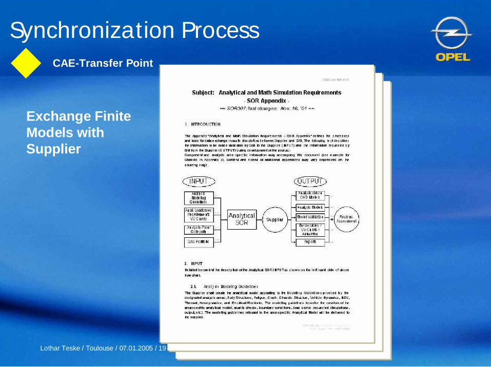
CAE-Transfer Point
Exchange FiniteModels withSupplier
Synchronization Process

Lothar Teske / Toulouse / 07.01.2005 / 20
CAE-Transfer Punkt
Å Modeling GuidelinesÅÅ Modeling GuidelinesModeling Guidelines É Virtual Vehicle ReportÉÉ Virtual VehicleVirtual Vehicle ReportReport
0 1 2 3
XYZ
Ç Standardized S/W PortfolioÇÇ StandardizedStandardized S/W PortfolioS/W Portfolio
Synchronization Process
Lothar Teske / Toulouse / 07.01.2005 / 21
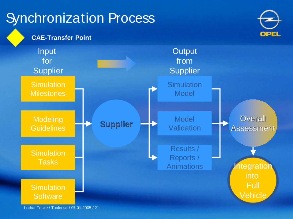
CAE-Transfer Point
SimulationMilestones
ModelingGuidelines
SimulationTasks
SimulationSoftware
Inputfor
Supplier
Outputfrom
Supplier
SimulationModel
ModelValidation
Results /Reports /
Animations
SupplierSupplier
IntegrationintoFull
Vehicle
OverallOverallAssessmentAssessment
Synchronization Process
Lothar Teske / Toulouse / 07.01.2005 / 22
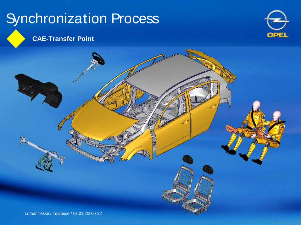
CAE-Transfer Point
Synchronization Process

Lothar Teske / Toulouse / 07.01.2005 / 23
Virtual Assessment
Timing
VIniVAVirtual Initial Vehicle AssessmentVAVA Virtual Architecture Vehicle AssessmentVCVA Virtual Concept Vehicle AssessmentVSVA Virtual Structure Vehicle AssessmentVIVA Virtual Integration Vehicle AssessmentVPVA Virtual Product/Process Validation Vehicle Assessment Synchronization
Program SOP 1. Quarter 2002 2. Quarter 2002 3. Quarter 2002 4. Quarter 2002 1. Quarter 2003 2. Quarter 2003
Proj 1 03VPVA
7.8.18.7.
Proj 2 04VPVA
6.12.8.11.
Proj 3 04VCVA 2
22.2.
VIVA
9.8.
VSVA
26.4.18.1. 12.7. 20.6.22.2.
Proj 4 05VCVA
16.8.
VIVA
7.2.
VSVA
15.11.12.7. 13.12.27.9.
Proj 5 05VCVA
19.7.
VIVA
14.3.
VSVA
18.12.17.5. 8.11. 14.2.23.8.21.6.
Proj 6 06VIniVA
31.1.
VAVA
18.7.13.6.
Proj 7 07
t.b.d.
t.b.d.
decision
Synchronization Process

Lothar Teske / Toulouse / 07.01.2005 / 24
Virtual Assessment
Data Maturity
Maturaty Definition
A Surface, Volume, Weight,Inertia,
4 Typical section, Layout
3 Surface model, Solid model(without or some radius,partwise based, Conceptcompletely clear, not 100%matched)
2 Solid models, Surface models(completely matched, withradius)
1 Solid model (high degree ofintegration, e.g. tooling data)
Synchronization Process

Lothar Teske / Toulouse / 07.01.2005 / 25
Virtual Assessment
DevelomentStatus
DevelomentStatus BenchmarkBenchmark
Load CaseLoad Case
SimulationResult
SimulationResult
AnalyzeType
AnalyzeType
NameSim. / Meas.
NameSim. / Meas.
SubsystemSubsystem TargetTargetPredecessorPredecessor
VILV VCV VSV VIV VVV
Status virtual Prototype Vectra MY 2002RohkarosserieGesamtsteifigkeit
Hersteller OPEL OPEL OPEL OPEL OPEL OPEL A BTyp J2900 J3200 NB J3200 NB J3200 NB J3200 NB J3200 NBModelljahr 1996 2004 2004 2004 2004 2004 1998 1997Entwicklungsphase 1996 FORDERUNG VlnlV VCV VSV VIV VVV PROD. PROD.Messung/Berechnung (S/V) 1996 IO SSTS§ S S S V S V VTORSION (mit Hilfsrahmen)
Steifigkeit mit Scheibe (kNm/deg) 11,0 16,0 (SSTS) 15,7 16,8 13,3 14,9 20,5 14,7Stei figkei t ohne Scheibe (kNm/deg) 6,1 11,0 DEV 9,9 8,9 8,9 9,2 11,3 10,7
Diagonale Maßänderungen (ohne Scheibe) 1,18
Frontscheibenöffnung (mm) 1,37 1,00 DEV 0,19 1,03 1,10 1,07 1,07 1,14Heckklappenöffnung (mm) 1,28 0,75 DEV 0,17 0,73 0,85 0,72 0,82 0,51Heckscheibenöffnung (mm) 2,09 1,00 DEV 0,03 1,88 1,00 1,25 1,03 0,93
Diagonale Maßänderungen (mit Scheibe) 121,4
Frontscheibenöffnung (mm) 0,07 0,15 DEV 0,18 0,18 0,19 0,20 0,12 0,28Vordertüröffnung (mm) 0,26 0,25 3.2.1.6.1.1.2 0,19 0,19 0,24 0,22 0,13 0,30Hintertüröffnung (A) (mm) 0,35 0,25 3.2.1.6.1.1.2 0,24 0,24 0,26 0,24 0,21 0,36Heckklappenöffnung (mm) 0,64 0,30 DEV 0,26 0,26 0,44 0,30 0,33 0,17Heckscheibenöffnung (mm) 0,08 0,20 DEV 0,24 0,24 0,23 0,38 0,21 0,27
BIEGUNG ( mit Scheibe, mit Hilfsrahmen )Steifigkeit Schweller (kN/mm) 12,0 16,0 3.2.1.6.1.1.1 19,0 20,2 18,9 21,3 21,5 18,5Stei figkei t 1. Querträger (kN/mm) 5,8 6,0 3.2.1.6.1.1.1 9,3 9,3 8,6 7,3 8,7 6,1Stei figkei t 2. Querträger (kN/mm) 4,8 5,0 3.2.1.6.1.1.1 8,0 8,0 6,8 6,8 8,2 4,1Steifigkeit Vorderrahmen (kN/mm) 11,2 10,0 3.2.1.6.1.1.1 10,6 10,6 8,6 11,4 14,7 6,2Steifigkeit Heck (kN/mm) 3,0 3,0 3.2.1.6.1.1.1 3,5 3,5 3,1 2,5 2,1 2,4Querverformung Seitenwand ( Heckab. ) (mm) 0,68 0,80 3.2.1.6.1.1.1 0,5 1,54 0,48Diagonalen - mit ScheibeVordertür Öffnung ( A ) (mm) 0,12 0,10 3.2.1.6.1.1.1 0,10 0,10 0,18 0,18 0,09 0,05Vordertür Öffnung ( B ) (mm) 0,57 0,40 3.2.1.6.1.1.1 0,25 0,25 0,34 0,32 0,32 0,44Hintertür Öffnung (A) (mm) 0,41 0,40 3.2.1.6.1.1.1 0,17 0,17 0,11 0,16 0,16 0,35Hintertür Öffnung (B) (mm) 0,03 0,10 3.2.1.6.1.1.1 0,03 0,03 0,03 0,07 0,01 0,06
MASSPDT 4.1 Unterboden (kg) 104,5 116,7 3.2.2.2 124,2 124,2 112,3 NA NAPDT 4.2 Aufbau (kg) 133,8 153,2 3.2.2.2 175,6 175,6 151,0 NA NABIW total 1) (IO-MASSE) (kg) 255,5 289,9 3.2.2.2 320,9 320,9 291,4 281,9 299,8 270,8
BENDING (with Glas)
(kN/mm)Stiffness Rocker -- > 12,0 16,0 3.2.1.6.1.1.1 20,219,0 18,9 21,3 21,5 18,5
Standardized Load Cases
Synchronization Process
Lothar Teske / Toulouse / 07.01.2005 / 26
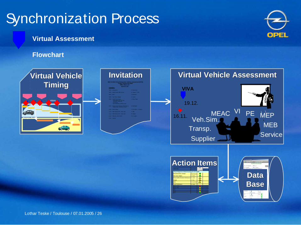
Virtual Assessment
Flowchart
Action ItemsAction ItemsVIVA
Acti on Item Res pons ible Assessme nt12. 12.2001
Due Da te
Virtual Integration V ehicle Assessm ent, 12.12.2001Body Data Sta tus, changes
S.Rosenplä nterM. Geyrhofer
Rear Door, Tailga te A. Nauerz
Body-In-White Structure Performan ce B. Justen
Fatigue U. Jung
NVH D. Jennewein
Crash Performanc e B. Justen
Danner Front 17.01.2002
Danner Rear 17.01.2002
Side 17.01.2002
Front 17.01.2002
Rear 17.01.2002
InvitationInvitationDELTA 3301 Virtual Integration Vehicle Assessment (VIVA)
Friday, August 9 th, 2002N55I Room 112
09:00- 11:30AGENDA:
09:00 Introduction K. Hieronimus
09:05 Master Model 008 Cont ent M. Siegel / T. Pohl
09:20 DMU P. Bernhard
09:35 Door Rear, Tailgate O. Czech
09:45 Crash Perform ance J. Perez -Freije- High-speed rear, AZT rear- Side ECE, Side Pole
- Front OD B - Belt Anchora ge, Shift ing Load
10:3 0 Body-in-whit e Structure Performan ce D. Warrington - Global static / dynamics / mass
10:50 Body Fatigue T. Tra n-Quoc / A. Nauerz
11:10 MEP Assessment Rear End A. Wild
11:15 MEB Assessment Rear End M. Gasper
11:20 Wrap Up, Action Items K.-H. Lepper
11:30 Adjourn
DataDataBaseBase
Virtual VehicleVirtual VehicleTimingTiming
VSVA
.
Design, Test
VIVA
19.12.
16.11. MEPPEMEAC VIVeh.Sim.
Virtual Vehicle AssessmentVirtual Vehicle Assessment
Supplier
MEBService
Transp.
Synchronization Process
Lothar Teske / Toulouse / 07.01.2005 / 27
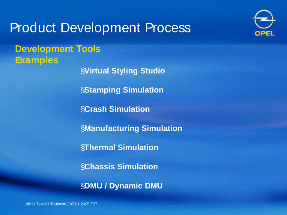
§Virtual Styling Studio
§Stamping Simulation
§Crash Simulation
§Manufacturing Simulation
§Thermal Simulation
§Chassis Simulation
§DMU / Dynamic DMU
Product Development ProcessDevelopment ToolsExamples

Lothar Teske / Toulouse / 07.01.2005 / 28
Development ToolsVirtual Styling Studio

Lothar Teske / Toulouse / 07.01.2005 / 29
Development ToolsVirtual Styling Studio

Lothar Teske / Toulouse / 07.01.2005 / 30
Development ToolsVirtual Styling Studio

Lothar Teske / Toulouse / 07.01.2005 / 31
Development StatusDevelopment Status Release StatusRelease Status
WrinklesWrinkles
ThinningThinning
Development ToolsStamping Simulation

Lothar Teske / Toulouse / 07.01.2005 / 32
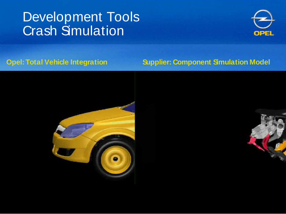
Development ToolsCrash Simulation
NEW ASTRA
´98 ASTRA
Number of Elements in Crash Model
Component ´98 ASTRA new ASTRABody-In-White 76.972 744.366Hang-On Parts 10.733 213.243Chassis 20.090 108.739Misc.* 6.619 332.087
Total 114.414 1.398.435* Trim, IP, Pedals, Dummies, Spotwelds, ...

Lothar Teske / Toulouse / 07.01.2005 / 33
´98 ASTRA
Component ´98 ASTRA new ASTRABody-In-White 76.972 744.366Hang-On Parts 10.733 213.243Chassis 20.090 108.739Misc.* 6.619 332.087
Total 114.414 1.398.435* Trim, IP, Pedals, Dummies, Spotwelds, ...
• Detailed Model of Interior Trim(IP, Seats, Steeringsystem,Pedals, Door Trim, …)
• Prediction of Crash Behavior ofComponents
NEW ASTRA
Development ToolsCrash Simulation
Number of Elements in Crash Model
Lothar Teske / Toulouse / 07.01.2005 / 34
Supplier: Component Simulation ModelOpel: Total Vehicle Integration
Development ToolsCrash Simulation

Lothar Teske / Toulouse / 07.01.2005 / 35
Development ToolsManufacturing Simulation
• Material Flow
Layout
Ergonomics
Lothar Teske / Toulouse / 07.01.2005 / 36
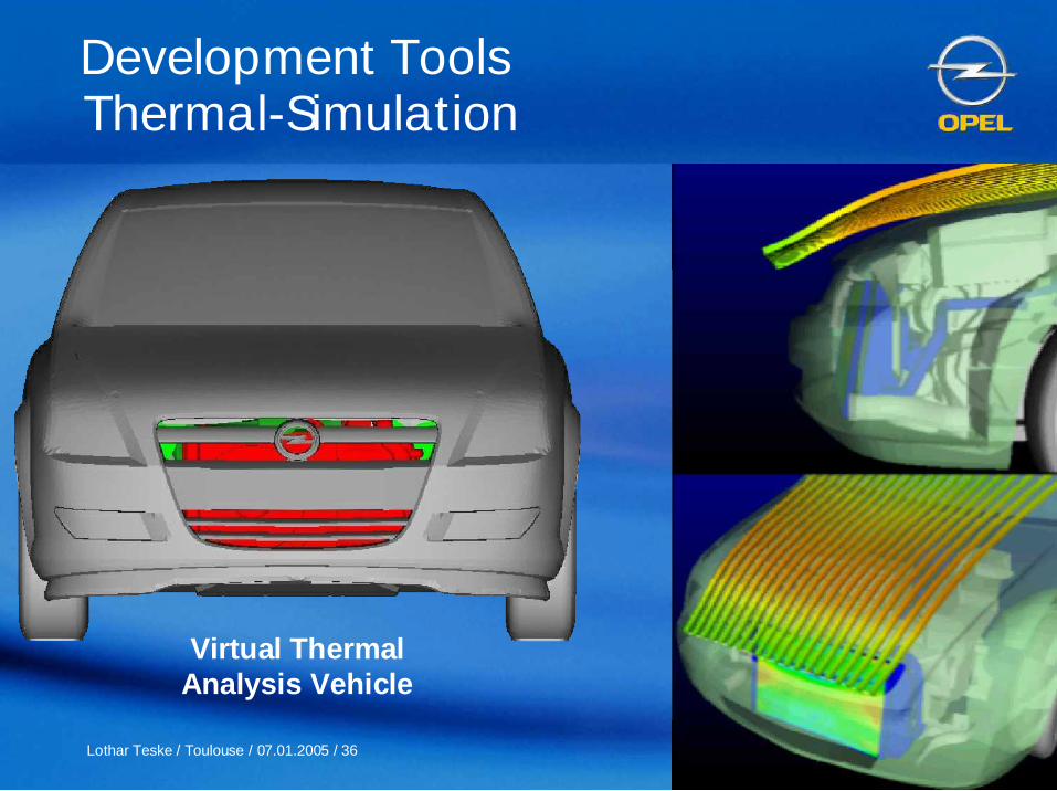
Thermal-Simulation
Virtual ThermalAnalysis Vehicle
Development Tools

Lothar Teske / Toulouse / 07.01.2005 / 37
Development ToolsThermal Simulation
Lothar Teske / Toulouse / 07.01.2005 / 38
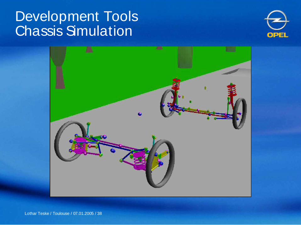
Development ToolsChassis Simulation

Lothar Teske / Toulouse / 07.01.2005 / 39
Development ToolsChassis Simulation

Lothar Teske / Toulouse / 07.01.2005 / 40
Development ToolsDynamic DMU
Static
DM
U
Dyna
mischer
DM
U
VisM
ockup
dyn. Clearance-Analyse
ClearanceProtocol
SweptVolume
dyn. Envelope -Geometry
Motion &Movie
Animation
MovementSimulation
GeometryPoints
MovementData
GeometryCondensation
3-DGeometry
EnvelopeGeometry

Lothar Teske / Toulouse / 07.01.2005 / 41
Development ToolsDMU

Lothar Teske / Toulouse / 07.01.2005 / 42
Development ToolsDynamic DMU i.e. Chassis

Lothar Teske / Toulouse / 07.01.2005 / 43
Development ToolsDynamic DMU i.e. Engine Movement

Lothar Teske / Toulouse / 07.01.2005 / 44
§ Short product cycles and fast trend changes in the markets will forcethe automotive industry to realize shorter development time frames.
§ The shorter timescales and resulting higher development work loading willlead to a further push towards the utilization of virtual methods in order tomeet increased pressure on costs and timing.
§ In this shortened process simultaneous, handling of latest, synchronizeddata releases by all development partners involved must be ensured.
§ The vehicle manufacturers will concentrate to a much greater degree oncoordination and integration within the vehicle development process.
§The development of integrated modules will become more and more theresponsibility of specialist suppliers.
Product Development ProcessSummary
Lothar Teske / Toulouse / 07.01.2005 / 45