ammonia industry—^today and...
TRANSCRIPT

PETROCHEMICAL DEVELOPMENTS SPECIALREPORT
Ammonia industry— t̂odayand tomorrowInnovations in technology and best practices facilitateeconomic survival for global operating companies
M. P. SUKUMARAN NAIR, FACT Ltd., Cochin, Kerala, India
The ammonia industry provides nitrogenous fertilizers fromhydrocarbon-based feedstocks. The first ammonia processwas developed 90 years ago. Over time, technology and
new equipment have improved operating costs and enabled build-ing large plants. Yet, most ammonia facilities use natural gas (NG)as a feedstock. Likewise, the ammonia process is an energy-inten-sive operation. Higher energy and feedstock costs have adverselyimpacted the profitability of older, smaller operating facilities.
Demand for ammonia and fertilizers by developing countriesincreases annually. However, higher operating costs devastate theprofitability of ammonia plants. Technology can be a solution tothis industry. New developments are reducing operating costs andfacilitating the use of other feedstock over natural gas.
TECHNOLOGY UPDATEOn the technology iront, the ammonia plant flowsheet and equip-
ment layout has endured minor changes from the original processingroute developed in the 1960s. This processing method is accepted asthe most efficient and economic route for ajiimonia production (Fig.5). However, every processing stage and unit operation has undergonesignificant and considerable improvements and unique innovations.These modifications improved the operating economics, increasedprocessing efficiencies, lowered environmentai burdens, upgradedoperational safety and reduced total plant/operation risks.
Feedstock sulfur removal . Feedstock NG and light hydro-carbons invariably contain small quantities of sulfur compounds,which are mostly downstream process catalysts. Consequently,these compounds are removed from the feed gas by hydrogenat-ing it to 350-400°C. The sulfur compounds are converted intohydrogen sulfide (H2S) in a desulfurizer, in the presence of cobaltmolybdenum (CoMo) catalyst. The H2S is adsorbed on palletizedzinc oxide to form zinc sulfide. The hydrogen, normally providedby the synthesis section, and the zinc sulfide remain in the adsorp-tion bed, which deactivates over time and must be replaced.
The desulfurization reaction is initiated by the hydrogenationstep. Organic sulfur compounds are converted into H^S andquantitatively absorbed on palletized zinc oxide:
ZnO + HjS -ZnS + H^O
This catalyst is manufactured from high-purity raw materials,essentially free of arsenic and chlorine that may poison down-stream catalysts. The sulfur pickup rate is very dependent on
temperature, porosity and surface area ofthe zinc oxide pellets. Anormal service life for desulfurization catalyst is 3-7 years.
Adiabat ic pre-ref o r m i n g . This process eases the burden ofendothermic tubular reforming. Adiabatic pre-reformmg improvesthe efficiency ofthe total reforming process and eliminates manyproblems encountered in conventional tubular steam reformers.Pre-reformer catalyst is nickel (Ni) based on magnesium alu-mina spinel oxide. It is characterized by high-reforming activity,improved tolerance for sulfur and greater resistance to carbon for-mation at low steam-to-carbon ratios. Such catalysts are availablefor hea^y hydrocarbon feedstock from NG to naphtha.
Tubular re forming . The desulfurized feed gas contains lessthan 0.1 parts per million (ppm) sulfur and is mixed with super-heated process steam. This mixture is heated to 500-600°G andintroduced to the primary reformer. 1 he reformer is usually arectangular-tubular furnace in which the feedstock-steam mixtureis heated using externally fired burners. The primary reformertubes contain Ni catalyst and are externally heated to support theendothermic reaction.
Typical reformer oudet temperatures range between 815°Cand9OO''C to minimize the GH4 slip. Reformer-exit GH4 equilibriumis favored by higher tube oudet temperature, higher steam-to-gasratio and lower exit pressure. All have tremendous technologicaland economic implications. A 5.5°C rise in the tube outlet tem-perature can reduce the feed input by 1.3% and yield an equalincrease of steam generated in the waste-heat recovery section.Metallurgical limitations of tubes, endothermic heat requirementsand economics of downstream pressure operations limit choices.
Steam-to-carbon ratio—the molar ratio of steam-to-reactivecarbon contained in the hydrocarbon maintained in the primaryreformer—varies from 2.8 to 3.4 with NG to naphtha. A highersteam-to-carbon ratio drives the reaction closer to the equilibriumand reduces hydrocarbon slip:
CH, + H , 0 -> CO + 3H,
-CO.
AH = + 206.3 KJ/mol
AH--4l.2KJ/mol
Two important developments in the reforming technologyoccurred regarding catalyst and metallurgy ofthe reformer tubes.Both developments are driven to increase adaptability to varyingfeedstock slates and increased energy efficiency. Continued
HYDROCARBON PROCESSING APRIL 2006 47

SPECIALREPORT PETROCHEMICAL DEVELOPMENTS
Experienced petrochemical—ammonia
The ammonia industry is a vital key in the productionof nitrogenous fertiiizers. It is one of the most developedsegments of the petrochemical processing industry. Eversince the invention of the Haber-Bosch process in 1913 andsubsequent developments spanning over 90 years in themodern ammonia industry, fixation of atmospheric nitrogenas ammonia and its subsequent conversion to agrochemicalscontribute to meet 40% of the world's protein needs. Globalammonia production in 2004 reached 141.4 million met-ric tons (MM metric tons), 90% of v /̂hich is directly used tomanufacture mineral fertilizers (Table 1). Fertilizer demand isprojected to increase 1.6%/yrfrom 2004 to 2010, and growthis occurring in developing nations of Asia-Pacific and in Rus-sia (Tables 1 and 2).
The ammonia industry consumes around 1.2% of theworld's energy resources (Fig. 1). Over the past three decades,significant improvements in the energy efficiency, safety andenvironmental friendliness of ammonia production havebeen achieved. Thus, the specific energy consumption, wastegeneration, greenhouse gas (GHG) emissions and accidentrate in the ammonia industry are trending downward.
Global ammonia trade has also increased significantly.Worldwide ammonia production increased by 7% in 2004;availability was in short supply in the inter-regional tradedue to capacity constraints and rising maritime-freight rates.Major production centers are the Former Soviet Union (FSU)and the Middle East where natural gas supplies are abun-dant (Table 1). Major ammonia importers are India and theUS. Nearly 62% of the 8.476 MM metric tons of ammoniaexported from the Middle East is sent to India. Last year, USdemand for imports increased (Table 2).
Price. The price for ammonia is highly volatile, with the lowestrecorded price of $106 (CFR India) per ton in October/Decem-ber 2002, and the highest as $326.27 (CFR India) in January/March 2004 (Fig. 2). The average price ranges between $117and $304 (CFR India). In 2003, approximately 13.776 MM met-ric tons of liquid ammonia was traded globally.
Major exporters are the Middle East (Saudi Arabia, Bah-rain and UAE), Former Soviet Union (Russia and Ukraine),Canada, Germany, The Netherlands, Indonesia and Trinidad.India, South Korea, Western Europe, Jordan, Latin Americaand the US imported the bulk of the ammonia produced inother countries.
Natural gas (NG), predominantly methane (CH4) is the bestfeedstock for ammonia production. A recent survey shows that71% ofthe world's ammonia capacity is based on NG. Otherfeedstock includes naphtha, LPG and refinery gases (5.6%),fuel oil and liquid residues (3.7%) and coal, coke and coke ovengas (19%). Developments for gasification suggest that coal isa potential prime feedstock for ammonia, especially due tounprecedented price increases for oil and NG. Continued
14
l e
1987 1991 1995 1998Year
2000 2004
Average energy consumption of ammonia facilities—1987to 2004.
350. 300
.gg250« | 2 0 0g | 1 5 0
'97 '98 "99 '00 '01 '02 '03 '04 '05Year
Ammonia pricing from 1996 to 2005.
A very high and stable catalytic activity is needed for favorableheat transfer and lower pressure drop in the tubes. It is possibleto significantly increase throughput under constant pressure dropand stable tube-wall temperatures. The carrier for the catalystmust have good mechanical strength, and the catalyst requireslarge surface area. Alkali-promo ted catalysts prevent carbon for-mation in the steam reformer and minimizes hot-band formationwhen reforming naphtha or NG.
Developments in furnace-tube metallurgy. Thereformer tubes, which are usually designed to limit creep-rupturelife to 100,000 hours, operate under severe conditions of an oxi-dizing environment. These processing conditions include a veryhot atmosphere containing corrosive oxides of sulfur, nitrogen andparticulates. The tube material is aiso under strain of carburizationand metal dusting, and is subjected to extensive cyclic thermal andpressure shock loadings. Thus, the tube construction materialsmust have proven mechanical strength, high-temperature corro-sion resistance and amenability to casting and welding. Moreover,they must be easily available at affordable costs.
The new alloys, such as HK 40 and a wide variety of modernsuper alloys, are possible construction materials for furnace tubes.Cast alloys are the prime choice; they tolerate significantly higherconcentrations of carbon, silicon, tungsten, molybdenum, etc.,which are added to enhance mechanical properties and increasecorrosion resistance. Within the modern ammonia processing, themetal working ofthe cast tubes has become more difficult.
Another elevated-temperature degradation process for austen-itic stainless steels is sensitization caused by precipitating chro-mium carbides preferentially at grain boundaries. It may occurduring fabrication from the heat of welding, improper heat treat-ment or through service exposure.
48 APRIL 2006 HYDROCARBON PROCESSING

PETROCHEMICAL DEVELOPMENTS SPECIALREPORT
Year
FIG. 3 " India's ammonia production from 1993 to 2004.
Tube failures in primary reformers are attributed to creeprupture, stress rupture, bowing or hot bands. Common failurecauses of reformer tubes include: over firing, thermal shocks,steam condensation over the catalyst, and impact of thermal andpressure cycling from frequent startups and shutdowns. Hence,monitoring the health ofthe tube is a vital aspect of reformeroperations. Regular assessment ofthe tube-wall temperature,maintaining a well-defined burner flame geometry and ensur-ing even flow through the tubes can achieve a better servicelife for the tube. The physical condition ofthe tubes shouldbe assessed during annual turnarounds through nondestruc-tive testing (NDT) methods; for creep detection, monitoringmethods include eddy current, ultrasonic or laser profilometrymethods.
Presently, the economic choice of tube metallurgy is based onlife cycle costs. Several reformers are revamped using improvedmetallurgy ofthe tube material with increased creep-rupturestrength and improved carburization resistance and drasticallyreduced plant outage. It has been well-established that it is morecost-effective to specify a material that will provide an extendedlife for areas that are difficult to repair—-or in components thatwould cause major shutdowns due to failure, such as the primaryreformer tubes, tn these situations, the original cost ofthe mate-rial is insignificant compared to the lost production resulting fromthe component failure.
The gas-heated reformer or the tandem reformer replaces thetubular reformer with a heat exchanger applying tubes filled with thereforming catalyst. Effluents from the secondary reformer provide
NG is also traded around globally in the form of liquefiednatural gas (LNG) and piped through cross-country pipe-lines. Major exporters of LNG are located in the Middle East,Russia, Southeast Asia, Australia, Algeria, Nigeria, Canadaand Mexico. Major LNG importers include Japan, EuropeanUnion, US, South Korea and Taiwan. Most long-distance NGpipelines are located in Europe and North America.
NG enjoyed a price advantage over other feedstocks fora long time due to restricted availability at close proxim-ity to oil fields, huge investments needed for liquefaction,transport of the cryogenic liquid, re-gasification and pipelineinfrastructure at the consumer's end. This situation has slowlychanged as increasing demand for NG has facilitated theconstruction of LNG terminals in different countries.
Compressed natural gas (CNG) is slowly emerging as alow-cost feedstock for ammonia plants. The technology forCNG capture, transport and delivery is proven. In addition,investments to capture and compress NG from stranded gasfields are lower than for LNG terminals.
Transport of CNG is simple and easy to implement. Ship-ping CNG is cheaper than LNG for distances up to 3,500 km.At greater distances, the shipping costs for CNG exceed LNGexpenses, thus making LNG more attractive as the transportmedia—more gas (three times the volume of gas) per ship-ment. With the ensured availability of CNG, coastal ammoniaplants based on naphtha or fuel oil may find it feasible tochange feedstocks to regain financial viability.
INDIAThe Indian ammonia industry has an installed annual
capacity of 12.8 MM metric tons, and the production during2003-04 was 12.53 MM metric tons (Fig. 3). Nearly 61% ofthe ammonia produced in India is based on NG. Of the 38plants, 35 are now operating and three are closed due to lackof viability under the new fertilizer pricing policy. Fifteenplants operate in the private sector, 14 in the public sectorand six in the cooperative sector. Besides a domestic produc-tion of 12.595 MM metric tons, India imported around 1.33MM metric tons of ammonia during 2003-04 (Table 2).
Supply and balance. International Fertilizer IndustryAssociation (IFA), based in Paris, estimated that the globalnitrogen supply and demand balance will remain tight inthe short term but will expand into a surplus situation insubsequent years. In terms of cumulative demand oversupply (total capability of ammonia), the growth in supplyis forecast at 2.5%/y compared with an annual growth indemand of 1.5%. A surplus is expected to emerge by 2006and to increase substantially by 2009, assuming that allannounced capacity projects are completed in time. How-ever, the growth rate of this surplus will start to decelerateby the end of the decade.
Between 2005 to 2009, new projects and expansions willadd about 24 MM metric tons of urea capacity, of which 60%will be located in consuming countries. In terms of regional
HYDROCARBON PROCESSING APRIL 2006 49

SPECIALREPORT PETROCHEMICAL DEVELOPMENTS
distribution. West Asia wil l contribute ciose to half of the
new capacity additions during this period, foilowed by China
with a 35% contribution and the remaining 15% will come
mostly from Russia and India.
The higher cost of NG prevailing in North America, West-
ern and Central Europe, Northeast Asia and India provide
no incentives for investments in modern, large and cost-
competitive capacity in the region. Instead, gas-rich regions
of West Asia, Russia and the Caribbean continue to provide
strong business perspectives for sustained investments. In
addition, several plants remain idle in the US and India due
to high feedstock cost for gas or liquid.
Due to recent hikes in crude oi! pricing, feedstock prices
for ammonia produaion—NG and naphtha—have increased
considerably. In India, the prevailing NG price along the HBJ
pipeline is $3-4.5 per MMBtu, whereas that of fuel oil is
$11 per MMBtu and for naphtha in the range of $14-15 per
MMBtu (Fig. 4). Increasing liquid feedstock prices have put
tremendous pressure on naphtha- and fuel oil-based plants
in India. Some plants are closed; others operate while incur-
ring heavy losses.
China and India, major importers of urea until the late
1990s, developed indigenous production capabilities and
stopped imports. China began exporting 1 MM metric tons
of urea by 2001. Global capacity buildup curtailed due to
loss of export markets to India and China. The situation is
slowly changing, and imports to India, restated in 2003,
may increase due to the likely closure of nearly 3 MM metric
tons of urea capacity fol lowing the changes in the fertilizer
pricing policy.
China does not have proven NG sources or easy access to
LNG. However, it is the largest coal producer in the world.
Hence, China continues its ammonia expansion program by
planning 10 coal-based plants to produce 3.7 MM metric tpy
of ammonia. In contrast, two major Indian coal-based ammo-
nia plants, which contributed significant expertise to coal
gasification technology, were shut down due to cost. From
the international scenario, technology will play a pivotal role
that will ensure the growing needs of fertilizers.
Other feedstocks for ammonia manufacture include light
hydrocarbons such as liquefied petroleum gas (LPG), fuel
oil, refinery residues and coal. These feedstocks have yet to
be proven for technical and commercial viability in modern
large-capacity plants.
Current t r e n d . The ammonia industry is construct ing
higher-capacity single-stream plants. Single-stream plants
with capacities ranging between 2,500 metric tpd and 3,000
metric tpd are operational. Capacities up to 5,000 tpd are
being planned by major technology suppliers. This achieve-
ment is possible through the continuous efforts to optimize
and improve ammonia synthesis technology. The benefits for
larger units include the advantages from economy-of-scale.
Doubling the size of a single-train unit can potentially reduce
the capital-related production costs by 20%. HP
Natural gas
ZnO *-
H2O,fuel
Air, ^power
Heat,power ^
Power • •
Power ^
Desulfurization
Primary reformer
+Secondary reformer
Shift conversion
i•CO2 removal
+Mettianation
Compression
+Ammonia synthesis
INH3
^ Z n S
^ Flue-gas
»-Heat
»"Heat
Condensate^ CO2
Heat, purge/flash gas
n C . 5 Ammonia process flow sheet using natural gas reforming.
the hear energy for the reforming reaction. Although this methodhas several advantages over the conventional tubular reformer, it is
yet to gain acceptance in modern large-capacity plants.
Flue gas leaving the radiant box has a temperature of 1,100°C.Only 50-60% ofthe heat supplied is directly used within the pro-
cess. The remaining enthalpy from the flue gas is recovered in the
flue-gas heat-recovery train to pre-heat the incoming feedstock,
generate steam, superheat steam and for other process require-
ments. The flue gas leaves the convection section and is vented
to atmosphere at 1 00-200°C, which is the main emission source
from the plant, h contains mainly carbon dioxide (CO2) and smallamounts of nitrogen oxides (NOJ, carbon monoxide (CO) andsulfur dioxide (SO2).
Secondary re forming . Secondary reforming is partial oxi-
dation of residual CH/, from the primary reformer. Hot processair is added through a specially designed burner into the reactor,
in which internal combustion occurs. The extent of primaryreforming is adjusted so that the air supplied to the secondary
reformer meets the heat balance and stoichiometric synthesis gasrequirement. The gas/air mixture is then passed over a Ni-con-taining catalyst where the reforming reaction proceeds to near
completion:
2CH4 + O2 (4-4N2) -> 2CO + 4H2O (+4N2)
AH =-71.4 KJ/mol
The secondary reforming catalyst is nickel oxide on aluminasupport and has a high thermal resistance and stable activity. Exit
gases exit from the secondary reformer at 950-1,000°C with most
50 APRIL 2006 HYDROCARBON PROCESSING

PETROCHEMICAL DEVELOPMENTS
TABLE 1. World ammonia situation—2003
Production
Country
China
India
US
Russia
Ukraine
Canada
Trinidad
Indonesia
Others
MM metric ton
30.207
12.595
8.768
9.113
3.934
3.646
3.574
4.254
32.70
Major exports
Country 1
Russia
Trinidad
Ukraine
Indonesia
Canada
Qatar
Saudi Arabia
VIM metric ton
2.4999
3.251
1.467
1.257
0.674
0.349
0.372
The Netherlands 0.476
Others 3.431
Major imports
Country MM metric ton
US
India
South Korea
France
Belgium
Others
5.415
1.085
0.841
0.609
0.477
5.35
World total 108.79 World 13.777 World 13.777
ofthe hydrocarbon in the feed converted toCO, CO2 and hydrogen (Hi) together wichadded nitrogen. The process gas is cooledto 35O-4OO°C in a process heat-recoverysteam boiler or boiler feedwater heater.
CO conversion. The cooled reformedgas contains 12-15% CO, with the bal-ance as H2, nitrogen (Ni), CO2 and smallamounts of argon and CH4 (dry basis).Most of the CO is converted to CO2 hypassing the process gas through a bed ofiron oxide/chromium oxide catalyst at370—400°C in a high-temperature con-verter and then over a copper oxide/zincoxide catalyst at about 200-220''C in alow-temperature converter. The residualCO content ofthe gas is 0.2-0.4%:
CO + H2O -> CO2 + H2
AH = -41.2 KJ/mol
Now, the gas contains mainly H2, N2.CO2 and excess process steam that wassupplied at the primary reforming stage.Most ofthe steam is condensed by coolingthe gas before it enters the CO2-removaIsystem. The condensate normally contains1,500-2,000 ppm ammonia and 800-1,200 ppm methanol (CH3OH), as wellas some CO2 and catalyst dust, etc. In olderplants, the process condensate is stripped ina column in which low-pressure (LP) steamis at the bottom. A mixture of steam andgases is vented to the atmosphere, while thestripped condensate after polishing is usedas boiler feedwater.
Medium-temperature shift (MTS) cata-lysts now replace standard high-temperatuirshift (HTS) catalysts in ammonia and hydro-gen plants operating at very low steam-to-car-bon ratios. Most low-temperature shifi: (LTS)catalysts in the market have high resistance
TABLE 2. Indian ammoniaimports—2003-04
Country
Qatar
Saudi Arabia
Iran
Bangladesh
UAE
Others
Total
MM metric ton
0.328
0.226
0.116
0.151
0.094
0.411
1.326
to water and chlorine poisoning. Recently,the methanol byproduct formation acrossLTS catalysts has become an environmen-tal issue. New-generation LTS catalysts arecapable of reducing methanol formation. Anew development in the HTS-shift converteris a specially designed boiler embedded in thecatalyst beds for in situ heat removal; thus, thereactor is very efficient.
CO2 removal, lhe economics of hydro-gen and ammonia manufacturing plantsheavily depend on the efficiency and reli-ability of CO2-removal systems. Over thelast 30 years of technology development,several innovations for this processingstep have increased absorption efficiency,reduced CO2 slip to ppmv, reduced energyrequirements to regenerate CO2, effec-tively reduce corrosion of plant equip-ment, emergence of nontoxic and envi-ronmentally friendly solvent systems andactivators for absorption, a shift fromphysical and chemical modes fot absorp-tion to a combination of both, improve-ments in mass transfer through better gas-liquid contact, and so on.
The converted gas usually contains 18-22% CO2, which is removed by chemicalor physical absorption process. The solvents
Bornas Stateof the Art
VISIT OUR BOOTH
OTC iVlAY
^3017 AT
2006
Series TSB Subsea ValveR.O.V. Interface API 17D
Emergency Shut-Down Valve
andmanufacturer of
Pipeline Ball valvesand Control System for:
-Subsea Systems-Emergency Shut
Dawn l/a/i/es-High pressure/carrasive
Ser\/ice-Modular dauhle hiack
and hieed Vali/es
ABV S.r.l.ViadiCoselli, 13/15
55060 Coselli - LUCCA. Italyphone +39.0583.403587
fax +39.0583.949920wv^w.abvvalves.com
e-mail: [email protected]
Select 91 at vwinw. HydrocarbonProcessing.com/RS
SPECIALREPORT PETROCHEMICAL DEVELOPMENTS
Power Air Heavy oil
Airseparation
unit
Gasification
Soot removal/recovery
Sulfur removal/recovery
HjO1
Heatpower
Shift conversion
CO2 removal
Liquid N^ wash
Power'
Power
Fuel
Compression
Ammonia synthesis
NH3
Auxiliary boiler
Heat
Slag
Sulfur
Heat
Condensate
CO;
Fuel gas
Heat, flashgas
Fuel gas
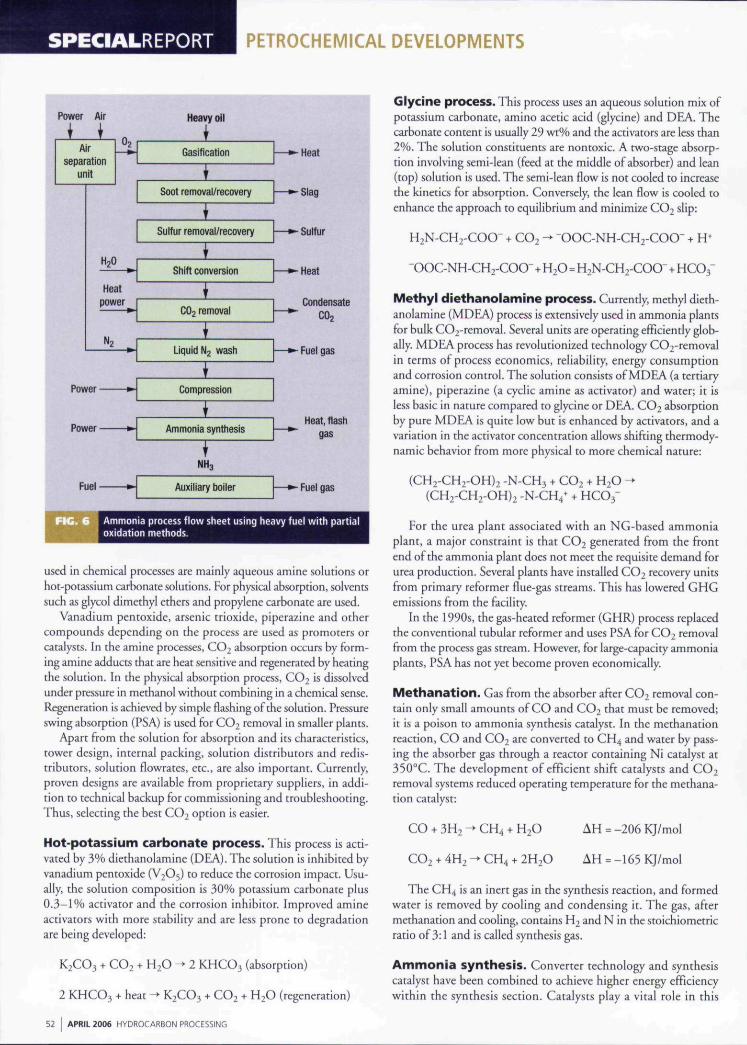
Ammonia process flow sheet using heavy fuel with partialoxidation methods.
used in chemical processes are mainly aqueous amine solutions orhot-potassium carbonate solutions. For physical absorption, solventssuch as glycol dimethyl ethers and propylene carbonate are used.
Vanadium pentoxide, arsenic trioxide, piperazine and othercompounds depending on the process are used as promoters orcatalysts. In the amine processes, CO2 absorption occurs by form-ing amine adducts that are heat sensitive and regenerated by heatingthe solution. In the physical absorption process, CO2 is dissolvedunder pressure in methanol without combining in a chemical sense.Regeneration is achieved by simple flashing of the solution. Pressureswing absorption (PSA) is used for CO2 removal in smaller plants.
Apart from the solution for absorption and its characteristics,tower design, internal packing, solution distributors and redis-tributors, solution flowrates, etc., are also important. Currently,proven designs are available from proprietary suppliers, in addi-tion to technical backup for commissioning and troubleshooting.Thus, selecting the best CO^ option is easier.
Hot-potassium carbonate process. This process is acti-vated by 3% diethanolaminc (DEA). The solution is inhibited byvanadium pentoxide {V2O5) to reduce the corrosion impact. Usu-ally, the solution composition is 30% potassium carbonate plus0 .3 -1% activator and the corrosion inhibitor. Improved amineactivators with more stability and are less prone to degradationarc being developed:
K2CO3 + CO2 + H2O -»• 2 KHCO3 (absorption)
2 KHCO3 + heat ^ K2CO3 + CO2 + H2O (regeneration)
Glycine process . This process uses an aqueous solution mix ofpotassium carbonate, amino acetic acid (glycine) and DEA. Thecarbonate content is usually 29 wt% and the activators are less than2%. The solution constituents are nontoxic. A two-stage absorp-tion involving semi-lean (feed at the middle of absorber) and lean(top) solution is used. The semi-lean flow is not cooled to increasethe kinetics for absorption. Conversely, the lean flow is cooled toenhance the approach to equilibrium and minimize CO2 slip:
H2N-CH2-COO- + CO2 -> OOC-NH-CH2-COO- -I- H*
^OOC-NH-CH2-COO- + H2O=H2N-CH2-COO-+HCO3-
Methyl diethanolamine process. Currently, methyl dieth-anolamine (MDEA) process is extensively used in ammonia plantsfor bulk CO2-removal. Several units are operating efficiently glob-ally. MDEA process has revolutionized technology C02-^removal
in terms of process economics, reliability, energy consumptionand corrosion control. The solution consists of MDEA (a tertiaryamine), piperazine (a cyclic amine as activator) and water; it isless basic in nature compared to glycine or DEA. CO2 absorptionby pure MDEA is quite low but is enhanced by activators, and avariation in the activator concentration allows shifting thermody-namic behavior from more physical to more chemical nature:
-N-CH3 -h CO2 -t- H2O-N-CH4* + HCO3-
For the urea plant associated with an NG-based ammoniaplant, a major constraint is that CO2 generated from the frontend ofthe ammonia plant does not meet the requisite demand forurea production. Several plants have installed CO2 recovery unitsfrom primary reformer flue-gas streams. This has lowered GHGemissions from the facility.
in the 1990s, the gas-heated reformer (GHR) process replacedthe conventional tubular reformer and uses PSA for CO2 removalfrom the process gas stream. However, for large-capacity ammoniaplants, PSA has not yet become proven economically.
M e t h a n a t i o n . Gas from the absorber after CO2 removal con-tain only small amounts of CO and CO2 that must be removed;it is a poison to ammonia synthesis catalyst. In the methanationreaction, CO and CO2 are converted to CH4 and water by pass-ing the absorber gas through a reactor containing Ni catalyst at35O''C. The development of efficient shift catalysts and CO2removal systems reduced operating temperature for the methana-tion catalyst:
CO + 3H2 -^ CH4 + H2O AH = -206 KJ/mol
CO2 + 4H2 -* CH4 + 2H2O AH = -165 KJ/mol
The CH4 is an inert gas in the synthesis reaction, and formedwater is removed by cooling and condensing it. The gas, aftermethanation and cooling, contains H2 and N in the stoichiometricratio of 3:1 and is called synthesis gas.
Ammonia synthesis. Converter technology and synthesiscatalyst have been combined to achieve higher energy efficiencywithin the synthesis section. Catalysts play a vital role in this
52 APRIL 2006 HYDR0CAR80N PROCESSING

PETROCHEMICAL DEVELOPMENTS SPECIALREPORT
developmenr. Most plants have installed pre-reduced catalyst tominimize startup time.
Synthesis gas is compressed to 100-200 bars using centrifugalcompressors, usually driven by high-pressure (HP) steam turbines.The reaction uses an iron catalyst at 35O-55O''C. Ammonia for-mation reaction is exothermic; thus, generated heat is used fotprocess steam production. Only 20-30% ofthe synthesis gas isconverted with each pass through the converter; thus, a recyclingloop is required to separate ammonia from the converter effluentand for admitting fresh makeup gas. During this operation, inertgases, contained in the synthesis gas (argon, methane, etc.), buildup in the synthesis loop and are maintained by a continuous purgeof 10-15%. The purge gas is cooled to separate NH3, scrubbedwith water to remove remaining ammonia, and used as fuel in thereformer or sent for hydrogen recovery.
Condensing product ammonia is achieved by a refrigerationsystem, and product ammonia is sent to the storage. The hquefiedproduct ammonia is either used directly in downstream plantsor stored in tanks. These tanks are usually fully refrigerated withcapacities ranging between 10,000 to 50,000 metric ton, pressur-ized spheres (3,000 metric ton) and bullets (20 metric ton)
= -91.8KJ/mol
The ammonia reaction equilibrium is favored by low tem-perature and high pressure. Catalyzed reaction rates are increasedby higher temperatures and pressure. Result: Most ammoniasynthesis loops use converters with multiple beds with inter-bedcooling.
A breakthrough in ammonia synthesis technology is the devel-opment of ruthenium metal-based catalyst on a proprietary gra-phitic structure. It has an intrinsic activity up to 20 times higherthan the conventional iroti-based catalyst. This catalyst can main-tain higher activity at low temperature and pressure, and operatesover a wide range of H2/N2 ratios.
Another development in ammonia-catalyst technology is thegranular wustite (non-stoichiometric ferrous oxide) catalyst withpromoters as Ca, aluminum, potassium, and rare-earth elementswith higher activity at low temperature and pressure, faster reduc-tion rates and increased mechanical strength and resistance topoisons.
Modern ammonia converters are designed on the radial-flowconcept, which has inherently low pressure drop, high conver-sion per pass, heat removal between catalyst beds and enableusing smaller sized catalyst. Thus, the recirculation rate andloop pressure drop remain low, reducing power requirementsfor compression. Most older plants are retrofitted with thenew converter baskets to save energy and reduce strain on loopequipment.
The ammonia purge gas recovery (PGR) system recoversconsiderable volumes of Hj that are otherwise lost as fuel to thefurnace. Designs based on both cryogenic technology and hol-low-fiber membranes have been successful. The former is moreefficient in recovering H2 from the purge, and the latter requiresa lower capital investment.
Partial oxidation of hydrocarbon or coal. Partial oxida-tion processes using heavy fuel oil, vacuum residue from petro-leum refining or coal offer an alternative route for ammoniaproduction. Process economics and investment depend on the
availability, cost and quality of feedstocks and oxygen. Otherfactors include environmental issues as disposal and treatmentof process byproducts and wastewater.
If the feedstock is heavy fuel oil with high-sulfur contentor coal, non-catalytic partial oxidation, at 50 bar pressure andl,400°C, is applied tor gasification (Fig. 6). Steam is added to thegasifier to moderate the gasification temperature. A cryogenic air-separation unit supplies oxygen and nitrogen to the process.
Reacting hydrocarbons with oxygen in the gasifiet producesCO and H2, as well as some CO2, CH4 and soot. Heat is recov-ered from the hot and dusty gases in a specially designed boiler.Soot from the process gas is removed by scrubbing it with waterand separated as a carbon slurry. Sulfur compounds in the feedare converted to H2S and separated from the process gas, usinga selective absorption agent (which could be the same as in theCO2 removal). Regenerated H2S is then converted to elementalsulfur by the Claus sulfur recovery process.
CO is then converted to CO2 by the water-shift reactionupon passing through two iron-catalyst beds with intermedi-ate cooling. The CO2 is removed by an absorption agent asin the reforming route. The residual traces of CO and CO2are removed in the final gas purification by a liquid nitrogenwash. Pure synthesis gas is generated; more N2 is added toprovide the stoichiometric H2/N2 ratio for ammonia produc-tion. The produced synthesis gas contains only H2 and N^—noinerts, Consequently, no purge for the ammonia synthesis loopis needed. Result: Loop efficiency is better than the steam-reforming process.
Coal. In coal gasification, the main stages are coal grinding,slurry preparation and slurry pulverization, in addition to thoserequired for the heavy fuel-oil processing. Higher initial invest-ment is needed. Higher energy consumption renders coal gas-ification as unviable. Still, efforts are underway to overcomethese disadvantages and capitalize on mega capacities; both arepartially driven by higher pricing for crude oil.
Co-production of ammonia. Gasification of residuesfrom refining operations is well-proven and established; severalinstallations, located in different countries, exist. This pro-cess involves non-catalytic partial oxidation of feedstocks withoxygen from an associated air-separation process to producesynthesis gas—a mixture of CO, H2 and smaller quantities ofCO2, H2S, soot, etc. Hot gases from the gasifier are cooled andcogenerate process steam by quenching it with water to removedust and particulate matter. Hydrogen sulfide is separated byMEA or glycol wash.
The recovered H2S and carbonyl sulfides (COS) are sent tothe Claus reaction; sulfur is recovered in the elemental form,which can be used for sulfuric acid or fertilizer production. Theentire sulfur in the residue is fixed as plant nutrient.
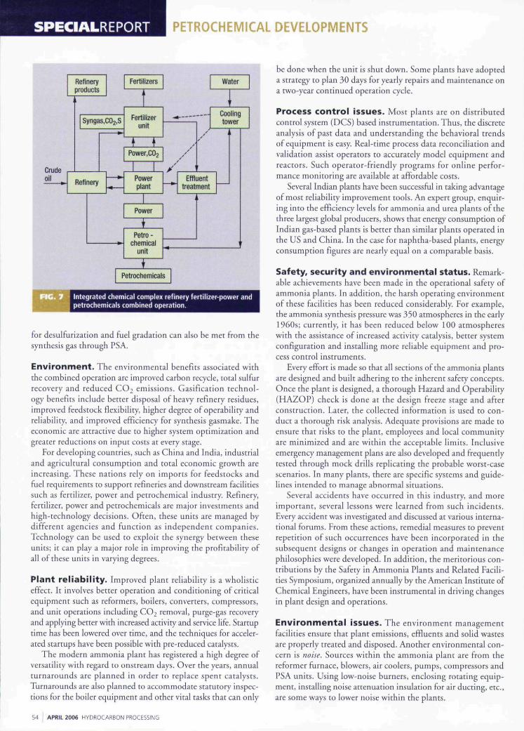
Synthesis gas generated from the process is similar to thatfrom other partial oxidation processes using furnace oil (FO) orlow-sulfur heavy stock (LSHS). Besides ammonia synthesis, itcan also be used for methanol manufacture or power generationin the integrated gasification and combined cycle mode (Fig.7). For ammonia synthesis, the CO in the gas is converted toCO2 and is stripped off. Produced H2 is mixed with N2 fromair separation in a wash column to the specification for theammonia synthesis gas. The refinery hydrogen requirement
HYDROCARBON PROCESSING APRIL 2006 53
SPECIALREPORT PETROCHEMICAL DEVELOPMENTS
Refineryproducts
I
oil
Svngas,C02,S
Refinery
».
Fertilizers
Fertilizerunit
S—r!Powerplant
Power
Petro -chemical
unit
> '
Water
•
Coolingtower
Effluenttreatment
Petrochemicals
Integrated chemical complex refinery fertilizer-power andpetrochemicals combined operation.
for desuifurization and fuel gradation can also be met from thesynthesis gas through PSA.
Environment. The environmental benefits associated withthe combined operation are improved carbon recycle, total sulfurrecovery and reduced COi emissions. Gasification technol-ogy benefits mclude better disposal ot hea\y refinery residues,improved feedstock flexibility, higher degree of operability andreliability, and improved efficiency for synthesis gasmake. Theeconomic are attractive due to higher system optimization andgreater reductions on input costs at every stage.
For developing countries, such as China and India, industrialand agricultural consumption and total economic growth areincreasing. These nations rely on imports for feedstocks andfuel requirements to support refineries and downstream facilitiessuch as fertilizer, power and petrochemical industry. Refinery,fertilizer, power and petrochemicals are major investments andhigh-technology decisions. Often, these units are managed bydifferent agencies and function as mdependent companies.Technology can be used to exploit the synergy between theseunits; it can play a major role in improving the profitability ofall of these units in varying degrees.
Plant reliability. Improved plant reliability is a wholisticeffect. It involves better operation and conditioning of criticalequipment such as reformers, boilers, converters, compressors,and unit operations including CO2 removal, purge-gas recoveryand applying better with increased activity and service life. Startuptime has been lowered over time, and the techniques for acceler-ated startups have been possible with pre-reduced catalysts.
The modern ammonia plant has registered a high degree ofversatility with regard to onstream days. Over the years, annualturnarounds are planned in order to replace spent catalysts.Turnarounds are also planned to accommodate statutory inspec-tions for the boiler equipment and other vital tasks that can only
be done when the unit is shut down. Some plants have adopteda strategy to plan 30 days for yearly repairs and maintenance ona two-year continued operation cycle.
Process control issues. Most plants are on distributedcontrol system (DCS) based instrumentation. Thus, the discreteanalysis of past data and understanding the behavioral trendsof equipment is easy. Real-time process data reconciliation andvalidation assist operators to accurately model equipment andreactors. Such operator-friendly programs for online perfor-mance monitoring are available at affordable costs.
Several Indian plants have been successful in taking advantageof most rehabihty improvement tools. An expert group, enquir-ing into the efficiency levels for ammonia and urea plants of thethree largest global producers, shows that energy consumption ofIndian gas-based plants is better than similar plants operated inthe US and China. In the case for naphtha-based plants, energyconsumption figures are nearly equal on a comparable basis.
Safety, security and environmental status. Remark-able achievements have been made in the operational safety ofammonia plants. In addition, the harsh operating environmentof these facilities has been reduced considerably. For example,the ammonia synthesis pressure was 350 atmospheres in the early1960s; currently, it has been reduced below 100 atmosphereswith the assistance of increased activity catalysis, better systemconfiguration and installing more reliable equipment and pro-cess control instruments.
Every effort is made so that all sections ofthe ammonia plantsare designed and built adhering to the inherent safety concepts.Once the plant is designed, a thorough Hazard and Operability(HAZOP) check is done at the design freeze stage and afterconstruction. Later, the collected information is used to con-duct a thorough risk analysis. Adequate provisions are made toensure that risks to the plant, employees and local communityare minimized and are within the acceptable limits. Inclusiveemergency management plans are also developed and frequentlytested through mock drills replicating the probable worst-casescenarios. In many plants, there are specific systems and guide-lines intended to manage abnormal situations.
Several accidents have occurred in this industry, and moreimportant, several lessons were learned from such incidents.Every accident was investigated and discussed at various interna-tional forums. From these actions, remedial measures to preventrepetition of such occurrences have been incorporated in thesubsequent designs or changes in operation and maintenancephilosophies were developed. In addition, the meritorious con-tributions by the Safety in Ammonia Plants and Related Facili-ties Symposium, organized annually by the American Institute ofChemical Engineers, have been instrumental in driving changesin plant design and operations.
Environmental issues . The environment managementfacilities ensure that plant emissions, effluents and solid wastesare properly treated and disposed. Another environmental con-cern is noise. Sources withm the ammonia plant are from thereformer furnace, blowers, air coolers, pumps, compressors andPSA units. Using low-noise burners, enclosing rotating equip-ment, installing noise attenuation insulation for air ducting, etc.,are some ways to lower noise within the plants.
54 APRIL 2006 HYDROCARBON PROCESSING

PETROCHEMICAL DEVELOPMENTS SPECIALREPORT
Management of hazardous waste materials has become amajor concern due to environmental issues. Major hazardouswastes generated from ammonia manufacturing operationsare primarily byproducts and/or spent catalysts consisting ofnickel, molybdenum, zinc, copper, vanadium, chromium,palladium, platinum, rhodium, etc. Other wastes includespent carbon from purification operations, and arsenic- andvanadium-bearing residues from CO2-removal operations. Inammonia plants, waste byproducts that require special disposalprocedures are chromium-bearing sludges from cooling watertreatment, chemical sludge from reactors, effluent and waste-water treatment plant, waste oil fromequipment, workshops and electricalinstallations, etc. There are earnest effortsfrom industry to voluntarily undertakesafe disposal of such waste materials inspecially designed treatment, storage anddisposal facilities.
Plant security is also a prime interestissue due to threats from worldwide ter-rorism. There is a growing need for moredetailed security guidelines to be adopted.These guidelines may be issued by profes-sional industrial organizations or by fed-eral government agencies.
Management outlook has also under-gone a paradigm shift. Lessons learnedfrom past failures, systematically investi-gating all failures for systems and equip-ment, practicing risk-based inspecticmprocedures and adopting reliability-cen-tered maintenance techniques are someofthe methods now practiced as standardoperating policies. On the operator's side,online performance monitoring is also acommonly adopted practice for streamlin-ing plant performance against the targets.Predictive trouble shooting and preventive
maintenance of equipment have been very successful in reducingplant outages.
Based on the operating experience and research, commonproblems encountered in plants are addressed to achieve a reli-able, efficient and sustainable operation. These efforts identitybest operating practices, explore retrofit options available andsuggest management methods for abnormal situations, and, thus,achieve total plant optimization. The driving force of productionand innovation within the ammonia industry is to become energyefficient, demonstrate environmental quality and yield economic/profitable operations in the global markets. HP
Or. M. P. Sukumaran Nairis the chief superintendent produc-tion at the Cochin Division facilitiesof The Fertilizers and Chemicais Tra-vancore (FACT) Ltd., India's pioneer
fertilizer and chemical manufacturing and engineer-ing consultancy organisation. He was the manag-ing director of the state-owned chior alkali major,Travancore Cochin Chemicais Ltd.. Cochin. iHe hoidsBS degrees in chemistry and chemicai engineeringand a postgraduate degree in ecology and environ-ment. Dr. Nair also holds an MBA and a doctorate inenvironmental management. He joined FACT in 1971and IS weli-experienced in process plant design andoperation, troubieshooting and management in theHPI, Dr, Nair is a fellow of the Institution of Engineers(India), was the chairman of the Institution of Engi-neers (india), Cochin, and a member of the AlChE.He IS also a member of severai expert advisory com-mittees to the central and state governments and haspublished over 50 papers. He is listed in the Marquis,Who's Who in the World and by the InternationalBiographical Centre, Cambridge, England, and canbe reached by e-mail: mpsn@vsnl com.
o
s
The Hallikainen
Vapour Pressure
Analyser from ATAC -
quality, reliability and
accuracy are built-in,
and fully
supported
by an
ISO 9001:2000
accredited
engineering
company, worldwide.
The Hallikainen
Vapour Pressure
Analyser correlates to
ASTM D323/DI267/
D519I.
Contact ATAC now
and let the pressure off
all your analyser needs.
THE MASTERS IN ANALYSIS
Analytical Technology and Control Ltd
Broadway, Market Lavington, Devizes,Wilts SN10 5RQ UK
Tel: +44(0) 1380 818411 Fax: +44(0) 1380 812733
E-mail: [email protected] Website: www.atacuk.com
Select 92 at www.HvdrocarbonProcessing.com/RS55
