amm master bridge v1 - xilinx - all programmable · 10 port descriptions ... the xilinx®...
TRANSCRIPT

AMM Master Bridge v1.0
LogiCORE IP Product Guide
Vivado Design SuitePG287 April 4, 2018

AMM Master Bridge v1.0 2PG287 April 4, 2018 www.xilinx.com
Table of ContentsIP Facts
Chapter 1: OverviewFeature Summary. . . . . . . . . . . . . . . . . . . . . . . . . . . . . . . . . . . . . . . . . . . . . . . . . . . . . . . . . . . . . . . . . . 6Applications . . . . . . . . . . . . . . . . . . . . . . . . . . . . . . . . . . . . . . . . . . . . . . . . . . . . . . . . . . . . . . . . . . . . . . 6Unsupported Features. . . . . . . . . . . . . . . . . . . . . . . . . . . . . . . . . . . . . . . . . . . . . . . . . . . . . . . . . . . . . . 6Licensing and Ordering . . . . . . . . . . . . . . . . . . . . . . . . . . . . . . . . . . . . . . . . . . . . . . . . . . . . . . . . . . . . . 7
Chapter 2: Product SpecificationStandards . . . . . . . . . . . . . . . . . . . . . . . . . . . . . . . . . . . . . . . . . . . . . . . . . . . . . . . . . . . . . . . . . . . . . . . . 8Performance. . . . . . . . . . . . . . . . . . . . . . . . . . . . . . . . . . . . . . . . . . . . . . . . . . . . . . . . . . . . . . . . . . . . . . 8Resource Utilization. . . . . . . . . . . . . . . . . . . . . . . . . . . . . . . . . . . . . . . . . . . . . . . . . . . . . . . . . . . . . . . . 9Parameter Descriptions . . . . . . . . . . . . . . . . . . . . . . . . . . . . . . . . . . . . . . . . . . . . . . . . . . . . . . . . . . . . 10Port Descriptions . . . . . . . . . . . . . . . . . . . . . . . . . . . . . . . . . . . . . . . . . . . . . . . . . . . . . . . . . . . . . . . . . 11
Chapter 3: Designing with the CoreClocking. . . . . . . . . . . . . . . . . . . . . . . . . . . . . . . . . . . . . . . . . . . . . . . . . . . . . . . . . . . . . . . . . . . . . . . . . 13Resets . . . . . . . . . . . . . . . . . . . . . . . . . . . . . . . . . . . . . . . . . . . . . . . . . . . . . . . . . . . . . . . . . . . . . . . . . . 13Arbitration . . . . . . . . . . . . . . . . . . . . . . . . . . . . . . . . . . . . . . . . . . . . . . . . . . . . . . . . . . . . . . . . . . . . . . 13Bridge Operation . . . . . . . . . . . . . . . . . . . . . . . . . . . . . . . . . . . . . . . . . . . . . . . . . . . . . . . . . . . . . . . . . 16
Chapter 4: Design Flow StepsCustomizing and Generating the Core . . . . . . . . . . . . . . . . . . . . . . . . . . . . . . . . . . . . . . . . . . . . . . . . 18Constraining the Core . . . . . . . . . . . . . . . . . . . . . . . . . . . . . . . . . . . . . . . . . . . . . . . . . . . . . . . . . . . . . 21Simulation . . . . . . . . . . . . . . . . . . . . . . . . . . . . . . . . . . . . . . . . . . . . . . . . . . . . . . . . . . . . . . . . . . . . . . 22Synthesis and Implementation . . . . . . . . . . . . . . . . . . . . . . . . . . . . . . . . . . . . . . . . . . . . . . . . . . . . . . 22Packaging Avalon Master Interface . . . . . . . . . . . . . . . . . . . . . . . . . . . . . . . . . . . . . . . . . . . . . . . . . . 22Creating an IP Integrator Design . . . . . . . . . . . . . . . . . . . . . . . . . . . . . . . . . . . . . . . . . . . . . . . . . . . . . 24
Chapter 5: Example DesignOverview . . . . . . . . . . . . . . . . . . . . . . . . . . . . . . . . . . . . . . . . . . . . . . . . . . . . . . . . . . . . . . . . . . . . . . . 25Implementing the Example Design. . . . . . . . . . . . . . . . . . . . . . . . . . . . . . . . . . . . . . . . . . . . . . . . . . . 26Simulating the Example Design. . . . . . . . . . . . . . . . . . . . . . . . . . . . . . . . . . . . . . . . . . . . . . . . . . . . . . 27
Send Feedback

AMM Master Bridge v1.0 3PG287 April 4, 2018 www.xilinx.com
Appendix A: DebuggingFinding Help on Xilinx.com . . . . . . . . . . . . . . . . . . . . . . . . . . . . . . . . . . . . . . . . . . . . . . . . . . . . . . . . . 28Debug Tools . . . . . . . . . . . . . . . . . . . . . . . . . . . . . . . . . . . . . . . . . . . . . . . . . . . . . . . . . . . . . . . . . . . . . 29
Appendix B: Additional Resources and Legal NoticesXilinx Resources . . . . . . . . . . . . . . . . . . . . . . . . . . . . . . . . . . . . . . . . . . . . . . . . . . . . . . . . . . . . . . . . . . 30Documentation Navigator and Design Hubs . . . . . . . . . . . . . . . . . . . . . . . . . . . . . . . . . . . . . . . . . . . 30References . . . . . . . . . . . . . . . . . . . . . . . . . . . . . . . . . . . . . . . . . . . . . . . . . . . . . . . . . . . . . . . . . . . . . . 30Revision History . . . . . . . . . . . . . . . . . . . . . . . . . . . . . . . . . . . . . . . . . . . . . . . . . . . . . . . . . . . . . . . . . . 31Please Read: Important Legal Notices . . . . . . . . . . . . . . . . . . . . . . . . . . . . . . . . . . . . . . . . . . . . . . . . 32
Send Feedback

AMM Master Bridge v1.0 4PG287 April 4, 2018 www.xilinx.com Product Specification
IntroductionThe Xilinx® LogiCORE™ multi-master AMM Master Bridge IP core connects AMM masters with AXI4 slaves. It converts traffic from the Avalon masters to AXI4-compatible traffic. Hence, it is also referred to as Avalon Memory Mapped (AMM) to AXI Bridge. This IP allows up to eight AMM masters to connect to an AXI slave.
Features• Supports 32, 64, 128, 256, 512, or 1,024-bits
data width on both AXI and Avalon sides.• Supports up to 1,024 burst count on Avalon
side.• AXI4 compliant.• Optional linear incremental of byte-enables
from LSB support for last data beat in a burst.
• Optional read only or write only support• Optional pipelining support for read
transactions.• Supports up to eight Avalon masters.• Round-robin arbitration for master
requests.• Up to 64-bit address support.• Error response indication separate for read
and write transactions along the corresponding master ID.
IP Facts
LogiCORE™ IP Facts TableCore Specifics
Supported Device Family(1)
UltraScale+™ FamiliesUltraScale™ Families
Zynq® UltraScale+ MPSoC7 Series FPGAs
Supported User Interfaces AXI4, Avalon
Resources Performance and Resource Utilization web page
Provided with CoreDesign Files VerilogExample Design VerilogTest Bench N/AConstraints File Xilinx Design Constraints (XDC)Simulation Model Not Provided
Supported S/W Driver N/A
Tested Design Flows(2)
Design Entry Vivado® Design Suite
Simulation For supported simulators, see theXilinx Design Tools: Release Notes Guide.
Synthesis Vivado Synthesis
SupportProvided by Xilinx at the Xilinx Support web page
Notes: 1. For a complete list of supported devices, see the Vivado IP
catalog.2. For the supported versions of the tools, see the
Xilinx Design Tools: Release Notes Guide.
Send Feedback

AMM Master Bridge v1.0 5PG287 April 4, 2018 www.xilinx.com
Chapter 1
OverviewThe top-level block diagram for the Xilinx® LogiCORE™ IP AMM Master Bridge with four Avalon masters support is shown in Figure 1-1. The Avalon traffic is arbitrated inside the bridge and generates one AXI4 master command at a time. The bridge functions as an Avalon slave on the Avalon interface and as an AXI4 master on the AXI4 interface. Figure 1-1 has for four Avalon masters and the bridge supports up to eight Avalon masters.
X-Ref Target - Figure 1-1
Figure 1-1: AMM Master Bridge Top-Level Block Diagram
Send Feedback

AMM Master Bridge v1.0 6PG287 April 4, 2018 www.xilinx.com
Chapter 1: Overview
Feature Summary• Supports 32, 64, 128, 256, 512, or 1,024-bits data width on both AXI and Avalon sides.• Supports up to 1,024 burst count on Avalon side.• AXI4 compliant.• Optional linear incremental of byte-enables from LSB support for last data beat in a
burst.• Optional read only or write only support• Optional pipelining support for read transactions.• Supports up to eight Avalon masters.• Round-robin arbitration for master requests.• Up to 64-bit address support.• Error response indication separate for read and write transactions along the
corresponding master ID.
ApplicationsWith no additional difficulty to you, the AMM Master Bridge helps connect available Avalon masters to the AXI4 slave peripherals in the Vivado® Design Suite.
Unsupported Features• Fixed wait states and fixed latencies are not supported.• No data width conversion that is, data width on AXI and Avalon side are the same.• No support for unaligned addresses.• No word addressing.• No partial/sparse byte-enables except for last beat.• No support for lock feature of Avalon.• No support for optional Response channel of the Avalon interface.• Only supports data width aligned address.
Send Feedback

AMM Master Bridge v1.0 7PG287 April 4, 2018 www.xilinx.com
Chapter 1: Overview
Licensing and OrderingThis Xilinx LogiCORE IP module is provided at no additional cost with the Xilinx Vivado Design Suite under the terms of the Xilinx End User License.
Information about other Xilinx LogiCORE IP modules is available at the Xilinx Intellectual Property page. For information about pricing and availability of other Xilinx LogiCORE IP modules and tools, contact your local Xilinx sales representative.
Send Feedback

AMM Master Bridge v1.0 8PG287 April 4, 2018 www.xilinx.com
Chapter 2
Product Specification
Standards• Processor Interface, AXI4: see the Vivado Design Suite: AXI Reference Guide (UG1037)
[Ref 6]• Avalon Interface Specifications [Ref 2]
PerformanceFor full details about performance and resource utilization, visit the Performance and Resource Utilization web page.
The performance characterization of this core was compiled using the margin system methodology. The details of the margin system characterization methodology are described in the Vivado Design Suite User Guide: Designing With IP (UG896) [Ref 11].
LatencyTable 2-1 shows the read and write latency.
Table 2-1: Latency
Function Parameter Latency
Readavs_read to axi_arvalid 9
axi_rvalid to avs_readdatavalid 0
Writeavs_write to axi_awvalid 9
avs_write to axi_wvalid 11
Send Feedback

AMM Master Bridge v1.0 9PG287 April 4, 2018 www.xilinx.com
Chapter 2: Product Specification
ThroughputTable 2-2 shows the throughput with data width 32-bit at 200 MHz (theoretical bandwidth = 6.4 Gb/s).
Resource UtilizationFor full details about performance and resource utilization, visit the Performance and Resource Utilization web page.
The approximate estimation of resources to use for this IP is the sum of the resources of the AXI DataMover IP and ~200 LUTs when configured for four Avalon masters.
Table 2-2: ThroughputChannel
Throughput BL = 1 BL = 8 BL = 16 BL = 32 BL = 64 BL = 256 BL = 512 BL = 1024
Read 14.2%0.908
88%5.632
93.62%5.99
96.7%6.18
98.32%6.29
99.57%6.37
99.78%6.38
99.89%6.39
Write 9.98%0.638
46.97%3.00
63.92%4.09
77.99%4.99
87.63%5.6
96.59%6.18
98.26%6.28
99.12%6.34
Send Feedback

AMM Master Bridge v1.0 10PG287 April 4, 2018 www.xilinx.com
Chapter 2: Product Specification
Parameter DescriptionsTable 2-3 shows the AMM Master Bridge parameters.
Table 2-3: Parameter DescriptionsParameter Default Value Range Description
C_AVA_ADDR_WIDTH 32 1 to 64 Address width of AMM address channel
C_AVA_DATA_WIDTH 32 32 to 1,024 Data width of AXI and AMM channels. Valid values are 32, 64, 128, 256, 512, and 1,024
C_ENABLE_PIPELINE 0 1, 0
Supports pipelining of read requests when 1.0 = pipeline disabled1 = pipeline enabled. Up to 16 read commands are pipelined.
C_MODE 2 0 to 20 = supports only read1 = supports only write2 = supports both read and write
C_NUM_MASTERS 1 1 to 8 Number of Avalon masters to support
C_AVA_BYTEENABLES 0 1, 0
Supports partial byte enables in a specific pattern for last data beat when 1.0 = disable byte enables1 = enable byte enables
Send Feedback

AMM Master Bridge v1.0 11PG287 April 4, 2018 www.xilinx.com
Chapter 2: Product Specification
Port DescriptionsTable 2-4 shows the AMM Master Bridge signals.
Table 2-4: AMM Master Bridge Interface SignalsSignal Name Interface Presence I/O Width Description
clk Clock M I 1 AXI clockaresetn Reset M I 1 AXI reset
write_error Error M O 1 Error indication in write command issued from a master.
write_error_valid Error M O 1 Write error is valid only when this signal is 1.
write_error_master_ID Error M O 3Error corresponds to this particular masters write command. Values from 0 to 8.
read_error Error M O 1 Error indication in read command issued from a master.
read_error_valid Error M O 1 Read error is valid only when this signal is 1.
read_error_master_ID Error M O 3Error corresponds to this particular masters read command. Values from 0 to 8.
m_axi_* AXI4 master M – – Master AXI ports to control AXI
slave.
Send Feedback

AMM Master Bridge v1.0 12PG287 April 4, 2018 www.xilinx.com
Chapter 2: Product Specification
avs_address_s#
Avalon slave
M I C_AVA_ADDR_WIDTH Avalon address channel
avs_byteenable_s# O I C_AVA_DATA_WIDTH/8Byte enables for write. This signal is present when C_BYTEENABLES = 1 & C_MODE > 0.
avs_write_s# O I 1Write indication from Avalon. Present only when write is supported. (CMODE = 1 or 2.
avs_read_s# O I 1Read indication from Avalon. Present only when C_MODE = 0 or 2.
avs_writedata_s# O I C_AVA_DATA_WIDTH Write data. Present only when C_MODE = 1 or 2.
avs_waitrequest_s# M O 1 Waitrequest to Avalon master
avs_readdata_s# O O C_AVA_DATA_WIDTH Read data output. Present only when C_MODE = 0 or 2.
avs_readdatavalid_s# O O 1Read data valid indication to Avalon master. Present only when C_MODE = 1 or 2.
avs_burstcount_s# M I 11 Burst count for commands
Notes: 1. [# is from 0 to {C_NUM_MASTERS - 1)];2. O in the “Presence” column of table indicates Optional signal and M indicates mandatory signals.
Table 2-4: AMM Master Bridge Interface Signals (Cont’d)
Signal Name Interface Presence I/O Width Description
Send Feedback
AMM Master Bridge v1.0 13PG287 April 4, 2018 www.xilinx.com
Chapter 3
Designing with the CoreThis chapter includes guidelines and additional information to facilitate designing with the core.
ClockingThe IP has a single clock domain, clk and the AXI4 and Avalon interfaces are clocked with the same clock.
ResetsThe system has an active-Low reset, aresetn. The reset has to be synchronous with clk. The same reset signal must be used by the Avalon masters as well as the AXI4 slave for the system to function properly. Separate resets to these systems can result in unexpected behavior.
ArbitrationRead and write requests from multiple Avalon masters are granted access in a round-robin mode. An Avalon master never issues a read and write request simultaneously. The arbitration is done separately for read and write channels and are independent of each other. The behavior of the arbitration logic is explained as follows:
Send Feedback

AMM Master Bridge v1.0 14PG287 April 4, 2018 www.xilinx.com
Chapter 3: Designing with the Core
A round-robin arbitration logic is used between the masters which requested a read or write transaction. The process of arbitration is as explained here:
• A Request is a vector created based on the Masters that have issued a request. A separate vector is created for reads and writes.
• Assume that Master2, Master3, and Master7 have issued a read/write request at the same time. The Request Vector has a value of 01000110.
In the first cycle of arbitration, Master2 is used, followed by Master3 and Master7.
• If Master5 requests a read/write while Master3 is underway, Master5 is used before Master7.
• If Master2 requests a read/write after it was used, then the new request is handled only after using all requests from Masters 3 to 7.
X-Ref Target - Figure 3-1
Figure 3-1: Arbitration Flow
Idle
Arbitrate
Grant Write Access to
Master [X]
Write Flow
Write_Requests[3:0]
Write Command – Completed
Idle
Arbitrate
Grant Read Access to
Master [X]
Read Flow
Read_Requests[3:0]
Command Completion
Command Pipelined
Pipeline
Support
Yes
No
wait_request_read_b
wait_request_write_bwait_request_b
X19466-063017
Send Feedback

AMM Master Bridge v1.0 15PG287 April 4, 2018 www.xilinx.com
Chapter 3: Designing with the Core
Read ArbitrationWhen the Bridge is configured to enable Pipeline, each read request is accepted and saved in a FIFO. A new read request is accepted even before the previous read data is produced.
Assume that Master2, Master3, and Master7 have issued a read requests at the same time. The Request Vector has a value of 01000110.
• Read address and burst count from Masters 2, 3, and 7 are queued into a FIFO in three consecutive cycles.
• The requests are processed from a FIFO in the same order. First, the read request for Master2 followed by Master3 and Master7.
• Meanwhile, the FIFO keeps accepting the read commands from master until the depth is full.
• The AXI4 read data is available in the same order.
If the bridge is configured without Pipelining, then a new read request is accepted only after the complete read data is provided for the precious read request.
Assume that Master2, Master3, and Master7 have issued a read requests at the same time.
• At first, read request of Master2 is processed.• The read request from Master3 is accepted only when the entire data for Master2 has
been read and sent to Avalon.• Similarly, the request from Master7 is processed only after request from Master3 is
completed.X-Ref Target - Figure 3-2
Figure 3-2: Read Arbitration Flow
wait request (Grant) m0, m1, m2
Command
Generator
Read
Command
MUX
Stream to Data
Converter
Read Data
DeMUX
Read Arbitration Logic
MM2S
DataMover
IO2 IO1 IO0
Read IO FIFOselect
read address, burstcount m0
m1
m2
Read request_m0
Read request_m1
Read request_m2
readdata and valid m0
m1
m2
Read Data Stream m_axi_(read)
m_axi_rdata
X19467-063017
Send Feedback

AMM Master Bridge v1.0 16PG287 April 4, 2018 www.xilinx.com
Chapter 3: Designing with the Core
Write ArbitrationAs Avalon does not support pipelining of writes, the Bridge waits for each write to be completed before accepting the next write command from the same or other Masters.
Assume that Master2, Master3, and Master5 have issued a write requests at the same time.
• At first, the write request of Master2 is accepted and processed.• After completion of write of Master2, the bridge accepts the write request of Master3.• Request from Master5 is accepted only after completion of the write of Master3.
Bridge OperationThe AMM Master Bridge uses the Xilinx® AXI DataMover LogiCORE IP Product Guide (PG022) [Ref 4] to convert the Avalon transaction to AXI4. The Bridge extracts the necessary information from the Avalon transaction and forms a command for the AXI DataMover. The data transfer on the AXI4 is handled by AXI DataMover.
Command GeneratorThe AXI DataMover accepts a command in a specific format containing the address and number of bytes to transfer. Separate commands are generated for read and write. When the Bridge is enabled with Pipelining, multiple read commands are posted to the AXI DataMover.
X-Ref Target - Figure 3-3
Figure 3-3: Write Arbitration Flow
wait request (Grant) m0, m1, m2
Command
Generator
Write
Command
MUX
Write Data
DeMUX
Write
Arbitration Logic
S2MM
DataMover
select
address, burstcount m0
m1
m2
Write request_m0
Write request_m1
Write request_m2
writedata and byte enables m0
m1
m2
m_axi_(write)
m_axi_wdata
Wired Logic
Comparator
Data to Stream Converter
Counter TLAST
X19468-063017
Send Feedback

AMM Master Bridge v1.0 17PG287 April 4, 2018 www.xilinx.com
Chapter 3: Designing with the Core
Address
The AMM Master Bridge supports Avalon Address width from 1 to 64. If the Avalon address width is < 32, then the AXI4 address width is fixed to 32 by padding the required MSB with zeros. The Bridge supports only data width aligned address. Issuing Avalon transaction with unaligned address results in undefined behavior.
Bytes to Transfer
The bytes to transfer is calculated using the burst_count and Data_width.
When the Bridge is configured with C_BYTE_ENABLES = 0, the ByteEnable bits on the Avalon interface are ignored.
When the Bridge is configured with C_BYTE_ENABLES = 1, the only ByteEnable bits on the last data beat of the Avalon interface are not ignored. Further, a sparse byteenable is only allowed on the last data beat in a specific pattern. Any other combination results in undefined behavior.
For example for a data width of 32-bits, the last byte-enables can only take values of 0001, 0011, 0111, or 1111. All the other patterns cause undefined behavior.
Error LogicThis IP has an error generation logic to indicate a SLVERROR, DECERROR, or INTERROR on the AXI response. The IP generates one error response per command which lasts for one clock only generating a valid indication and also the master ID from which the error causing command is issued. The master IDs are from 0 to 7 indicating the eight masters, s0 to s7 respectively.
Write and read commands have separate error indications. Both are self-clearing in a clock cycle. Error = 0 indicates no error and Error = 1 implies an error on the AXI response.
The error responses from two read or two write commands issued by a master are in order. While the error response for a read and write can come out of order.
Send Feedback
AMM Master Bridge v1.0 18PG287 April 4, 2018 www.xilinx.com
Chapter 4
Design Flow StepsThis chapter describes customizing and generating the core, constraining the core, and the simulation, synthesis and implementation steps that are specific to this IP core. More detailed information about the standard Vivado® design flows and the IP integrator can be found in the following Vivado Design Suite user guides:
• Vivado Design Suite User Guide: Designing IP Subsystems using IP Integrator (UG994) [Ref 10]
• Vivado Design Suite User Guide: Designing with IP (UG896) [Ref 11]• Vivado Design Suite User Guide: Getting Started (UG910) [Ref 12]• Vivado Design Suite User Guide: Logic Simulation (UG900) [Ref 13]
Customizing and Generating the CoreThis section includes information about using Xilinx tools to customize and generate the core in the Vivado Design Suite.
If you are customizing and generating the core in the Vivado IP integrator, see the Vivado Design Suite User Guide: Designing IP Subsystems using IP Integrator (UG994) [Ref 10] for detailed information. IP integrator might auto-compute certain configuration values when validating or generating the design. To check whether the values do change, see the description of the parameter in this chapter. To view the parameter value, run the validate_bd_design command in the Tcl console.
You can customize the IP for use in your design by specifying values for the various parameters associated with the IP core using the following steps:
1. Select the IP from the Vivado IP catalog.2. Double-click the selected IP or select the Customize IP command from the toolbar or
right-click menu.
For details, see the Vivado Design Suite User Guide: Designing with IP (UG896) [Ref 11] and the Vivado Design Suite User Guide: Getting Started (UG910) [Ref 12].
Note: Figures in this chapter are an illustration of the Vivado Integrated Design Environment (IDE). The layout depicted here might vary from the current version.
Send Feedback

AMM Master Bridge v1.0 19PG287 April 4, 2018 www.xilinx.com
Chapter 4: Design Flow Steps
Figure 4-1 shows the AMM Master Bridge Vivado IDE main configuration screen.
The following settings are generally applicable:
• Component Name – The component name is used as the base name of output files generated for the module. Names must begin with a letter and must be composed from characters: a to z, 0 to 9 and "_".
• Avalon Address Width – This parameter specifies the address width of avs_address ports. Select a value to match the Avalon master address width. The width of the AXI address ports is derived from this parameter. AXI_Address_Width is 32 when the Avalon address width is < 32 and equals the Avalon address width when it is > 32. Table 4-1 shows an example of the Avalon and AXI address widths.
Table 4-1: Avalon and AXI Address Width Information:
• Data Width – Specifies the width of data buses of AXI and Avalon interfaces. Same data width for AXI and Avalon interface.
• ByteEnable Support – Avalon write transactions support byteenables for last data beat of a transfer when this parameter is enabled. When disabled, optional byteenable port of the Avalon is removed.
X-Ref Target - Figure 4-1
Figure 4-1: AMM Master Bridge Customize IP
Avalon Address AXI Address0x4 0x00000004
0x40000004 0x400000040x2440000008 0x2440000008
Send Feedback

AMM Master Bridge v1.0 20PG287 April 4, 2018 www.xilinx.com
Chapter 4: Design Flow Steps
• Pipelining – Avalon read commands are accepted and saved in a FIFO when pipelining is enabled. The pipeline depth is 16.
• Number of Avalon Masters – Specifies the number of Avalon slave interfaces for the bridge.
• Mode of Operation – Bridge can also support only read or only write transactions.
All the parameters specified in the customization are applicable to all the Avalon slave interfaces of the bridge. Different parameters cannot be specified for different slave interfaces.
User ParametersTable 4-2 shows the relationship between the fields in the Vivado IDE and the User Parameters (which can be viewed in the Tcl Console).
Output GenerationFor details, see the Vivado Design Suite User Guide: Designing with IP (UG896) [Ref 11].
Table 4-2: Vivado IDE Parameter to User Parameter RelationshipParameter Default Value Range Description
C_AVA_ADDR_WIDTH 32 1 to 64 Address width of Avalon MM address channel
C_AVA_DATA_WIDTH 32 32, 64, 128, 256, 512, or 1024 Data width of AXI and AVM MM channels
C_ENABLE_PIPELINE 0 1, 0
Supports pipelining of read requests when 1.0 = pipeline disabled1 = pipeline enabled. Up to 16 read commands are pipelined
C_MODE 2 0 to 20 = supports only read1 = supports only write2 = supports both read and write
C_NUM_MASTERS 1 1 to 8 Number of Avalon masters to support
C_AVA_BYTEENABLES 0 1, 0
Supports partial byte enables in a specific pattern for last data beat when 1.0 = disable byte enables1 = enable byte enables
Send Feedback

AMM Master Bridge v1.0 21PG287 April 4, 2018 www.xilinx.com
Chapter 4: Design Flow Steps
Constraining the CoreThis section contains information about constraining the core in the Vivado Design Suite.
Required ConstraintsThis section is not applicable for this IP core.
Device, Package, and Speed Grade SelectionsThis section is not applicable for this IP core.
Clock FrequenciesThis section is not applicable for this IP core.
Clock ManagementThis section is not applicable for this IP core.
Clock PlacementThis section is not applicable for this IP core.
BankingThis section is not applicable for this IP core.
Transceiver PlacementThis section is not applicable for this IP core.
I/O Standard and PlacementThis section is not applicable for this IP core.
Send Feedback

AMM Master Bridge v1.0 22PG287 April 4, 2018 www.xilinx.com
Chapter 4: Design Flow Steps
SimulationFor comprehensive information about Vivado simulation components, as well as information about using supported third-party tools, see the Vivado Design Suite User Guide: Logic Simulation (UG900) [Ref 13].
IMPORTANT: For cores targeting 7 series FPGAs or Zynq-7000 devices, UNIFAST libraries are not supported. Xilinx IP is tested and qualified with UNISIM libraries only.
Synthesis and ImplementationFor details about synthesis and implementation, see the Vivado Design Suite User Guide: Designing with IP (UG896) [Ref 11].
Packaging Avalon Master InterfaceFor system migration, the Avalon Master IP has to be packaged for Vivado using the Avalon bus interface (Figure 4-2). This allows Avalon IP to integrate with the Vivado IP integrator system.
To package the Avalon slave IP, follow the steps mentioned in the Vivado Design Suite Tutorial: Creating and Packaging Custom IP (UG1119) [Ref 9].
X-Ref Target - Figure 4-2
Figure 4-2: AMM Master Bridge Packaging
Send Feedback

AMM Master Bridge v1.0 23PG287 April 4, 2018 www.xilinx.com
Chapter 4: Design Flow Steps
Figure 4-3 shows the bus interface with one Avalon slave interface.
Figure 4-4 shows the bus interface with eight Avalon slave interface.
X-Ref Target - Figure 4-3
Figure 4-3: AMM Master Bridge with One Avalon Slave interface
X-Ref Target - Figure 4-4
Figure 4-4: AMM Master Bridge with Eight Avalon Slave interface
Send Feedback
AMM Master Bridge v1.0 24PG287 April 4, 2018 www.xilinx.com
Chapter 4: Design Flow Steps
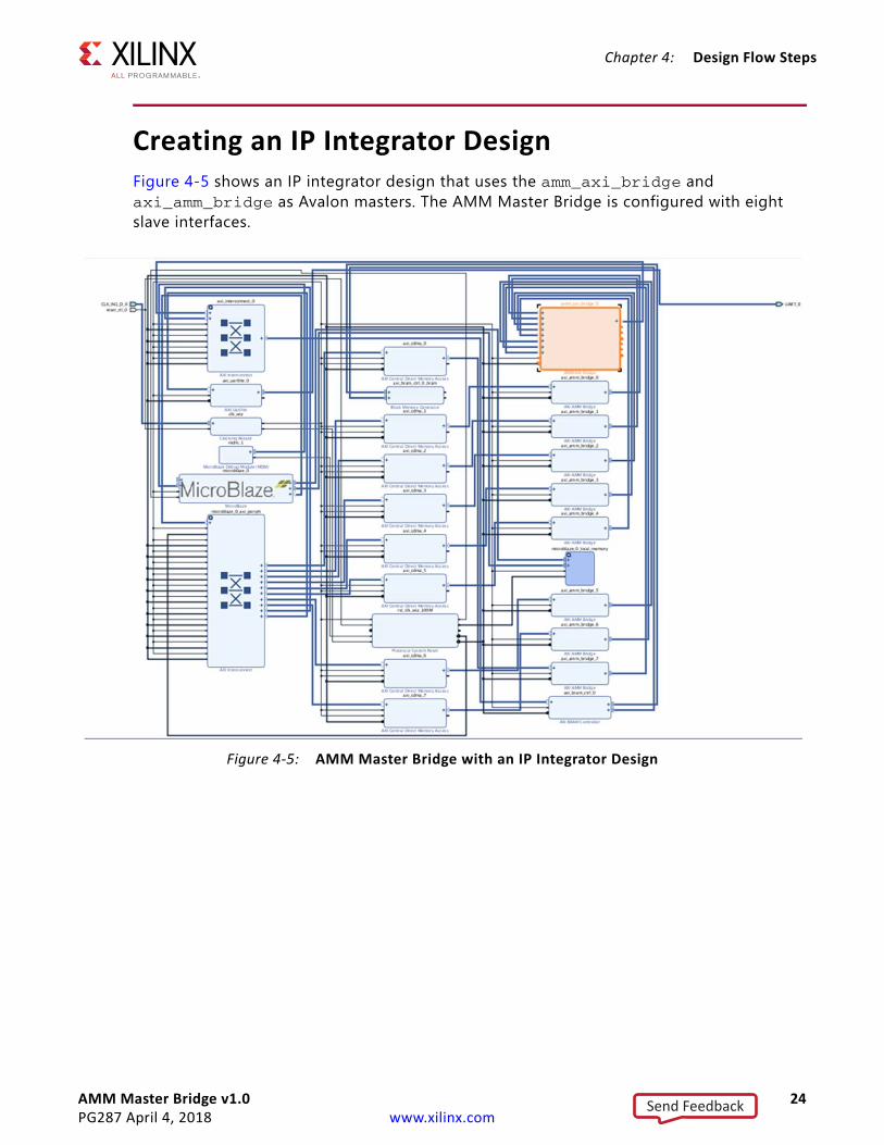
Creating an IP Integrator DesignFigure 4-5 shows an IP integrator design that uses the amm_axi_bridge and axi_amm_bridge as Avalon masters. The AMM Master Bridge is configured with eight slave interfaces.
X-Ref Target - Figure 4-5
Figure 4-5: AMM Master Bridge with an IP Integrator Design
Send Feedback

AMM Master Bridge v1.0 25PG287 April 4, 2018 www.xilinx.com
Chapter 5
Example DesignThis chapter contains information about the example design provided in the Vivado® Design Suite.
OverviewThe example design demonstrates the functioning of the AMM Master Bridge. An Avalon Master is modeled to generate the write and read transactions from a specified address location. The read data is then compared with the write data. Each master writes and reads from the different address location of the memory. If the read and write data for each master matches, the test is said to be completed successfully.
The example design contains the following:
• An instance of AMM Master Bridge as DUT• Selected number of modeled Avalon masters for each slave interface of DUT• AXI block RAM controller to act as AXI slave to the AXI Bridge• XPM single port RAM as memory block• Clocking wizard and reset generator for generating clock and synchronous reset for the
systemNote: The Avalon master and the example design are not generic configurations. The Avalon master and example design are generated based on IP configuration of DUT. Any changes in the models are not recommended. The Avalon slave in the example design works only with the corresponding bridge configuration.
Send Feedback

AMM Master Bridge v1.0 26PG287 April 4, 2018 www.xilinx.com
Chapter 5: Example Design
Implementing the Example DesignAfter following the steps described in Chapter 4, Customizing and Generating the Core, implement the example design using the following instructions:
1. Right-click the core in the Hierarchy window, and select Open IP Example Design.2. A new window pops up, asking you to specify a directory for the example design. Select
a new directory or keep the default directory.3. A new project is automatically created in the selected directory and it is opened in a new
Vivado IDE window.4. In the Flow Navigator (left pane), click Run Implementation and follow the directions.
Example Design Directory StructureIn the current project directory, a new project named <component_name>_ex is created and the files are generated in <component_name>_example.src/sources_1/ip/<component_name>/ directory. This directory and its subdirectories contain all the source files that are required to create the AMM Master Bridge example design.
X-Ref Target - Figure 5-1
Figure 5-1: AMM Master Bridge Example Design
Reset Generator
axi_*
Clocking Wizard
AXI Block RAM Controller
+
XPM RAM
Checker
Bridge
status
Avalon Master 1
Avalon Master 2
Avalon Master 3
test result
ava_axi_master1
ava_axi_master2
ava_axi_master3
X19718-081817
Send Feedback

AMM Master Bridge v1.0 27PG287 April 4, 2018 www.xilinx.com
Chapter 5: Example Design
The example design directory is created in imports/. It contains the following generated example design top files:
• <component_name>_exdes.v – Top-level HDL file for the example design• ava_master.v – Example design for the Avalon master model
Simulating the Example DesignUsing the example design delivered as part of the AMM Master Bridge, you can quickly simulate and observe the behavior of the core.
Setting up the SimulationThe Xilinx simulation libraries must be mapped to the simulator. To set up the Xilinx simulation models, see the Vivado Design Suite User Guide: Logic Simulation (UG900) [Ref 13]. To switch simulators, click Simulation Settings in the Flow Navigator (left pane). In the Simulation options list, change Target Simulator.
The example design supports functional (behavioral) and post-synthesis simulations. For information how to run simulation, see the Vivado Design Suite User Guide: Logic Simulation (UG900) [Ref 13].
Simulation ResultsThe simulation script compiles the Avalon Master Bridge example design and supporting simulation files. It then runs the simulation and checks that it completed successfully.
If the test passes, the following message is displayed:
Test Completed Successfully
If the test hangs, the following message is displayed:
Test Failed: Done not receive in 6 ms
If the test fails, the following message is displayed:
Test Failed
Send Feedback

AMM Master Bridge v1.0 28PG287 April 4, 2018 www.xilinx.com
Appendix A
DebuggingThis appendix includes details about resources available on the Xilinx Support website and debugging tools.
Finding Help on Xilinx.comTo help in the design and debug process when using the AMM Master Bridge, the Xilinx Support web page contains key resources such as product documentation, release notes, answer records, information about known issues, and links for obtaining further product support.
DocumentationThis product guide is the main document associated with the AMM Master Bridge. This guide, along with documentation related to all products that aid in the design process, can be found on the Xilinx Support web page or by using the Xilinx Documentation Navigator.
Download the Xilinx Documentation Navigator from the Downloads page. For more information about this tool and the features available, open the online help after installation.
Answer Records Answer Records include information about commonly encountered problems, helpful information on how to resolve these problems, and any known issues with a Xilinx product. Answer Records are created and maintained daily ensuring that users have access to the most accurate information available.
Answer Records for this core can be located by using the Search Support box on the main Xilinx support web page. To maximize your search results, use proper keywords such as
• Product name• Tool message(s)• Summary of the issue encountered
A filter search is available after results are returned to further target the results.
Send Feedback

AMM Master Bridge v1.0 29PG287 April 4, 2018 www.xilinx.com
Appendix A: Debugging
For the AMM Master Bridge Master Answer Record see Xilinx Answer 69656
Technical SupportXilinx provides technical support at the Xilinx Support web page for this LogiCORE™ IP product when used as described in the product documentation. Xilinx cannot guarantee timing, functionality, or support if you do any of the following:
• Implement the solution in devices that are not defined in the documentation.• Customize the solution beyond that allowed in the product documentation. • Change any section of the design labeled DO NOT MODIFY.
To contact Xilinx Technical Support, navigate to the Xilinx Support web page.
Debug ToolsThere are many tools available to address AMM Master Bridge design issues. It is important to know which tools are useful for debugging various situations.
Vivado Design Suite Debug FeatureThe Vivado® Design Suite debug feature inserts logic analyzer and virtual I/O cores directly into your design. The debug feature also allows you to set trigger conditions to capture application and integrated block port signals in hardware. Captured signals can then be analyzed. This feature in the Vivado IDE is used for logic debugging and validation of a design running in Xilinx devices.
The Vivado logic analyzer is used with the logic debug IP cores, including:
• ILA 2.0 (and later versions)• VIO 2.0 (and later versions)
See the Vivado Design Suite User Guide: Programming and Debugging (UG908) [Ref 15].
Send Feedback
AMM Master Bridge v1.0 30PG287 April 4, 2018 www.xilinx.com
Appendix B
Additional Resources and Legal Notices
Xilinx ResourcesFor support resources such as Answers, Documentation, Downloads, and Forums, seeXilinx Support.
Documentation Navigator and Design HubsXilinx® Documentation Navigator provides access to Xilinx documents, videos, and support resources, which you can filter and search to find information. To open the Xilinx Documentation Navigator (DocNav):
• From the Vivado® IDE, select Help > Documentation and Tutorials.• On Windows, select Start > All Programs > Xilinx Design Tools > DocNav.• At the Linux command prompt, enter docnav.
Xilinx Design Hubs provide links to documentation organized by design tasks and other topics, which you can use to learn key concepts and address frequently asked questions. To access the Design Hubs:
• In the Xilinx Documentation Navigator, click the Design Hubs View tab.• On the Xilinx website, see the Design Hubs page.Note: For more information on Documentation Navigator, see the Documentation Navigator page on the Xilinx website.
ReferencesThese documents provide supplemental material useful with this product guide:
1. Instructions on how to download the ARM® AMBA® AXI specifications are at ARM AMBA Specifications. See the:
Send Feedback

AMM Master Bridge v1.0 31PG287 April 4, 2018 www.xilinx.com
Appendix B: Additional Resources and Legal Notices
° AMBA AXI4 Protocol Specification
° AMBA4 AXI4-Stream Protocol Specification2. Avalon Interface Specifications 3. AMM Slave Bridge LogiCORE IP Product Guide (PG258)4. AXI DataMover LogiCORE IP Product Guide (PG022)5. 7 Series FPGAs Data Sheet: Overview (DS180)6. Vivado Design Suite: AXI Reference Guide (UG1037)7. Xilinx Software Development Kit User Guide: System Performance Analysis (UG1145)8. System Performance Analysis of an All Programmable SoC (XAPP1219)9. Vivado Design Suite Tutorial: Creating and Packaging Custom IP (UG1119)10. Vivado Design Suite User Guide: Designing IP Subsystems using IP Integrator (UG994)11. Vivado Design Suite User Guide: Designing with IP (UG896)12. Vivado Design Suite User Guide: Getting Started (UG910)13. Vivado Design Suite User Guide: Logic Simulation (UG900)14. ISE to Vivado Design Suite Migration Guide (UG911)15. Vivado Design Suite User Guide: Programming and Debugging (UG908)16. Vivado Design Suite User Guide: Implementation (UG904)
Revision HistoryThe following table shows the revision history for this document.
Date Version Revision04/04/2018 1.0 Changed existing title ‘Avalon Memory Mapped to AXI Bridge v1.0’ to ‘AMM
Master Bridge v1.0’.10/04/2017 1.0 Initial Xilinx release.
Send Feedback

AMM Master Bridge v1.0 32PG287 April 4, 2018 www.xilinx.com
Appendix B: Additional Resources and Legal Notices
Please Read: Important Legal NoticesThe information disclosed to you hereunder (the “Materials”) is provided solely for the selection and use of Xilinx products. To the maximum extent permitted by applicable law: (1) Materials are made available "AS IS" and with all faults, Xilinx hereby DISCLAIMS ALL WARRANTIES AND CONDITIONS, EXPRESS, IMPLIED, OR STATUTORY, INCLUDING BUT NOT LIMITED TO WARRANTIES OF MERCHANTABILITY, NON-INFRINGEMENT, OR FITNESS FOR ANY PARTICULAR PURPOSE; and (2) Xilinx shall not be liable (whether in contract or tort, including negligence, or under any other theory of liability) for any loss or damage of any kind or nature related to, arising under, or in connection with, the Materials (including your use of the Materials), including for any direct, indirect, special, incidental, or consequential loss or damage (including loss of data, profits, goodwill, or any type of loss or damage suffered as a result of any action brought by a third party) even if such damage or loss was reasonably foreseeable or Xilinx had been advised of the possibility of the same. Xilinx assumes no obligation to correct any errors contained in the Materials or to notify you of updates to the Materials or to product specifications. You may not reproduce, modify, distribute, or publicly display the Materials without prior written consent. Certain products are subject to the terms and conditions of Xilinx’s limited warranty, please refer to Xilinx’s Terms of Sale which can be viewed at https://www.xilinx.com/legal.htm#tos; IP cores may be subject to warranty and support terms contained in a license issued to you by Xilinx. Xilinx products are not designed or intended to be fail-safe or for use in any application requiring fail-safe performance; you assume sole risk and liability for use of Xilinx products in such critical applications, please refer to Xilinx’s Terms of Sale which can be viewed at https://www.xilinx.com/legal.htm#tos.AUTOMOTIVE APPLICATIONS DISCLAIMERAUTOMOTIVE PRODUCTS (IDENTIFIED AS “XA” IN THE PART NUMBER) ARE NOT WARRANTED FOR USE IN THE DEPLOYMENT OF AIRBAGS OR FOR USE IN APPLICATIONS THAT AFFECT CONTROL OF A VEHICLE (“SAFETY APPLICATION”) UNLESS THERE IS A SAFETY CONCEPT OR REDUNDANCY FEATURE CONSISTENT WITH THE ISO 26262 AUTOMOTIVE SAFETY STANDARD (“SAFETY DESIGN”). CUSTOMER SHALL, PRIOR TO USING OR DISTRIBUTING ANY SYSTEMS THAT INCORPORATE PRODUCTS, THOROUGHLY TEST SUCH SYSTEMS FOR SAFETY PURPOSES. USE OF PRODUCTS IN A SAFETY APPLICATION WITHOUT A SAFETY DESIGN IS FULLY AT THE RISK OF CUSTOMER, SUBJECT ONLY TO APPLICABLE LAWS AND REGULATIONS GOVERNING LIMITATIONS ON PRODUCT LIABILITY.© Copyright 2017-2018 Xilinx, Inc. Xilinx, the Xilinx logo, Artix, ISE, Kintex, Spartan, Virtex, Vivado, Zynq, and other designated brands included herein are trademarks of Xilinx in the United States and other countries. All other trademarks are the property of their respective owners.
Send Feedback