american association for laboratory accreditation · used, 2subject to the guidance on rounding...
TRANSCRIPT

American Association for Laboratory Accreditation
G118: Guidance for Defining the Scope of Accreditation for Calibration Laboratories
Document Revised: February 4, 2016
Page 1 of 34
L:\Guidance\G118 – Guidance for Defining the Scope of Accreditation for Calibration Laboratories
G118: Guidance for Defining the Scope of Accreditation for Calibration Laboratories
February 2016
2016 by A2LA. All rights reserved. No part of this document may be reproduced in any form or by any means without the prior written permission of A2LA.
American Association for Laboratory Accreditation
G118: Guidance for Defining the Scope of Accreditation for Calibration Laboratories
Document Revised: February 4, 2016
Page 2 of 34
L:\Guidance\G118 – Guidance for Defining the Scope of Accreditation for Calibration Laboratories
Table of Contents
I. Introduction and scope .................................................................................................. 3 II. Flexibility and responsiveness .................................................................................... 3 III. Contents of calibration scopes of accreditation ....................................................... 4 IV. Recommended descriptors ............................................................................................ 6 V. Use of the word “generate” on scopes of accreditation ........................................... 7 VI. The use of the International System of units (SI) and other systems of units . 7 VII. Model scope of accreditation ........................................................................................ 9 VIII. APPENDICES .................................................................................................................. 11 APPENDIX A: Hardness ......................................................................................................... 11 APPENDIX B: Dimensional testing ...................................................................................... 23 APPENDIX C: Durometer ....................................................................................................... 29 APPENDIX D: Adjustable threaded ring gages ................................................................. 30 IX. Definitions ............................................................................................................................ 31 Document Revision History .................................................................................................... 34
American Association for Laboratory Accreditation
G118: Guidance for Defining the Scope of Accreditation for Calibration Laboratories
Document Revised: February 4, 2016
Page 3 of 34
L:\Guidance\G118 – Guidance for Defining the Scope of Accreditation for Calibration Laboratories
I. Introduction and scope The scope of accreditation of a calibration laboratory is the official and detailed statement of the activities for which the laboratory is accredited. The formulation and assessment of the scope of accreditation represents the core of the accreditation process. The role of the Accreditation Body is to ensure (to an adequate degree of confidence) that the laboratory has the competence to offer the service defined in the scope1. Scopes of accreditation serve two purposes:
a) To define the specific areas of a laboratory’s activities which are covered by the laboratory’s accreditation (it is recognized that other activities may be undertaken by a laboratory for which it has not sought public recognition of its competence);
b) To provide the user of an accredited laboratory with a clear description of the
specific calibrations covered by the accreditation; The purpose of this document is to address sources of variability to the extent possible so that all calibration scopes have the same general appearance and level of detail and to outline the requirements for scopes of accreditation. II. Flexibility and responsiveness Assessors and staff need to consider the level of detail included in each scope of accreditation to ensure that there is a practical balance between the amount of information needed by the users of our accredited laboratories and flexibility on the part of accredited laboratories to offer their services within appropriate scopes of their recognized competence. Too much detail in scopes results in unnecessary demands for constant changes in scopes of accreditation, resulting in processing delays on our end and unwarranted restriction of competent services to laboratory users. Too little detail can result in a laboratory offering accredited calibration service in an area in which it has not been assessed. In determining the appropriate balance between detail of scopes and flexibility, consideration should be given to the ability of individual labs to update or modify generic methods or to implement new methods (to take account of technological progress or to satisfy changing needs of clients), provided that such changes do not involve significant deviation from the scope and are made only after proper notification to the accreditation body. Above all, the fundamental considerations relating to the format and information content of scopes have to do with the objectives of having a scope in the first place: the needs of the accredited laboratory and its users which bear on the necessity for consistency following
1 ILAC – G18:04/2010 Guideline for the Formulation of Scopes of Accreditation for Laboratories
American Association for Laboratory Accreditation
G118: Guidance for Defining the Scope of Accreditation for Calibration Laboratories
Document Revised: February 4, 2016
Page 4 of 34
L:\Guidance\G118 – Guidance for Defining the Scope of Accreditation for Calibration Laboratories
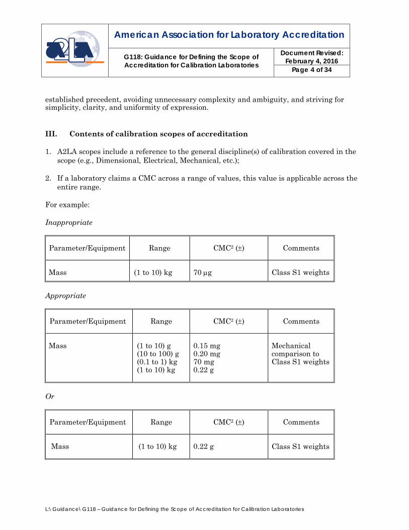
established precedent, avoiding unnecessary complexity and ambiguity, and striving for simplicity, clarity, and uniformity of expression. III. Contents of calibration scopes of accreditation 1. A2LA scopes include a reference to the general discipline(s) of calibration covered in the
scope (e.g., Dimensional, Electrical, Mechanical, etc.);
2. If a laboratory claims a CMC across a range of values, this value is applicable across the entire range.
For example: Inappropriate
Parameter/Equipment Range
CMC2 (±)
Comments
Mass
(1 to 10) kg
70 µg
Class S1 weights
Appropriate
Parameter/Equipment
Range
CMC2 (±)
Comments
Mass
(1 to 10) g (10 to 100) g (0.1 to 1) kg (1 to 10) kg
0.15 mg 0.20 mg 70 mg 0.22 g
Mechanical comparison to Class S1 weights
Or
Parameter/Equipment
Range
CMC2 (±)
Comments
Mass
(1 to 10) kg
0.22 g
Class S1 weights

American Association for Laboratory Accreditation
G118: Guidance for Defining the Scope of Accreditation for Calibration Laboratories
Document Revised: February 4, 2016
Page 5 of 34
L:\Guidance\G118 – Guidance for Defining the Scope of Accreditation for Calibration Laboratories
Per ILAC-P14:01/2013, particular care should be taken when the measurand covers a range of values. This is generally achieved through employing one or more of the following methods for expression of the uncertainty:
• A single value, which is valid throughout the measurement range. • A range. In this case a calibration laboratory should have proper assumption
for the interpolation to find the uncertainty at intermediate values. • An explicit function of the measurand or a parameter. • A matrix where the values of the uncertainty depend on the values of the
measurand and additional parameters. • A graphical form, providing there is sufficient resolution on each axis to obtain at
least two significant figures for the uncertainty.
3. The numerical value of the expanded uncertainty is given to, at most, two significant figures. Further the following applies:
1) The numerical value of the measurement result shall in the final statement be rounded to the least significant figure in the value of the expanded uncertainty assigned to the measurement result. 2) For the process of rounding, the usual rules for rounding of numbers shall be used, subject to the guidance on rounding provided i.e in Section 7 of the GUM2.
4. “Generate” is only used for electrical and microwave/RF disciplines in scopes of accreditation. See section V for more information.
5. Both the International System of units (SI) and US Industry accepted-unit symbols are allowed on scopes, however, unit symbols that are defined in a test method (for example - ASTM) are written exactly as specified in the test method and individual variations are not permitted.
6. When a laboratory lists a specification, or standard method on the scope of
accreditation, if the entirety of the specification or standard method cannot be adhered to when performing the calibration the limitation of the specification or standard method is included on the scope of accreditation.
2 Evaluation of measurement data – Guide to the expression of uncertainty in measurement JCGM 100:2008 (GUM 1995 with minor corrections).
American Association for Laboratory Accreditation
G118: Guidance for Defining the Scope of Accreditation for Calibration Laboratories
Document Revised: February 4, 2016
Page 6 of 34
L:\Guidance\G118 – Guidance for Defining the Scope of Accreditation for Calibration Laboratories
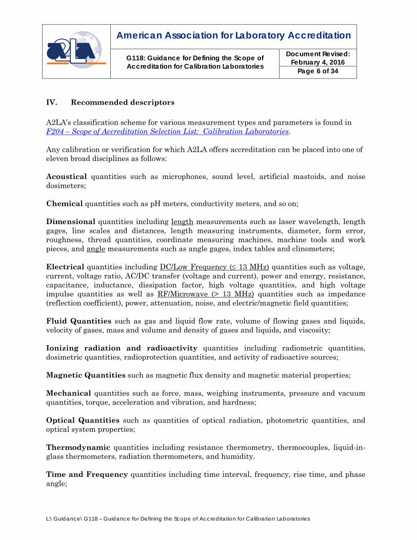
IV. Recommended descriptors A2LA’s classification scheme for various measurement types and parameters is found in F204 – Scope of Accreditation Selection List: Calibration Laboratories. Any calibration or verification for which A2LA offers accreditation can be placed into one of eleven broad disciplines as follows: Acoustical quantities such as microphones, sound level, artificial mastoids, and noise dosimeters; Chemical quantities such as pH meters, conductivity meters, and so on; Dimensional quantities including length measurements such as laser wavelength, length gages, line scales and distances, length measuring instruments, diameter, form error, roughness, thread quantities, coordinate measuring machines, machine tools and work pieces, and angle measurements such as angle gages, index tables and clinometers;
Electrical quantities including DC/Low Frequency (≤ 13 MHz) quantities such as voltage, current, voltage ratio, AC/DC transfer (voltage and current), power and energy, resistance, capacitance, inductance, dissipation factor, high voltage quantities, and high voltage impulse quantities as well as RF/Microwave (> 13 MHz) quantities such as impedance (reflection coefficient), power, attenuation, noise, and electric/magnetic field quantities;
Fluid Quantities such as gas and liquid flow rate, volume of flowing gases and liquids, velocity of gases, mass and volume and density of gases and liquids, and viscosity;
Ionizing radiation and radioactivity quantities including radiometric quantities, dosimetric quantities, radioprotection quantities, and activity of radioactive sources;
Magnetic Quantities such as magnetic flux density and magnetic material properties; Mechanical quantities such as force, mass, weighing instruments, pressure and vacuum quantities, torque, acceleration and vibration, and hardness;
Optical Quantities such as quantities of optical radiation, photometric quantities, and optical system properties; Thermodynamic quantities including resistance thermometry, thermocouples, liquid-in-glass thermometers, radiation thermometers, and humidity.
Time and Frequency quantities including time interval, frequency, rise time, and phase angle;

American Association for Laboratory Accreditation
G118: Guidance for Defining the Scope of Accreditation for Calibration Laboratories
Document Revised: February 4, 2016
Page 7 of 34
L:\Guidance\G118 – Guidance for Defining the Scope of Accreditation for Calibration Laboratories
Any question concerning how a measurement not listed above should be classified can be answered simply by identifying the measurand or unit of measure. For example, calibration of electrical temperature indicators/controllers is sometimes placed under the “thermodynamic” section, but since the measurand is, for example, voltage, the proper classification is under “electrical”. V. Use of the word “generate” on scopes of accreditation Scopes of accreditation, particularly in the electrical field, currently use the word “generate” to describe a laboratory’s ability to generate a quantity with a certain level of uncertainty. For example, “DC Volts – Generate” has been taken to mean that a laboratory can generate one or several multiples and/or submultiples of a volt and that its representation of this quantity is accurate to within the claimed level of uncertainty. Thus, laboratories with this capability can calibrate devices used to measure DC Volts. Although this usage is most prevalent in electrical scopes of accreditation, the same idea is not extended to other disciplines where the inadequacy of this concept for describing a laboratory’s calibration capabilities would not be clear. As such, the use of the “generate” term is only currently used for the electrical and microwave/RF disciplines in scopes of accreditation. Other considerations will be made on a case-by case basis upon written request from the laboratory. VI. The use of the International System of units (SI) and other systems of units This section provides information on issues relating to punctuation and layout of unit and quantity symbols on scopes of accreditation. International System of units NIST Special Publications 330, The International System of Units (SI), and 811, Guide for the Use of the International System of Units (SI) as well as ASTM SI10 American National Standard for Use of the International System of Units(SI): The Modern Metric System, are the primary guidance documents for the use of the SI system of units on A2LA scopes of accreditation. A2LA follows the principles of these documents as closely as possible, however, it is recognized that some obsolete system of units (e.g. inch-pound) is so deeply embedded in American society that it is impossible to present scopes of accreditation solely in terms of the SI. Therefore, it is necessary to strike a balance between best practice (exclusive use of the SI) and practical necessities. The units of the SI and those units recognized for use with the SI are used to express the values of quantities. Equivalent values in other units are given in parentheses following values in acceptable units when deemed necessary for the intended audience.
American Association for Laboratory Accreditation
G118: Guidance for Defining the Scope of Accreditation for Calibration Laboratories
Document Revised: February 4, 2016
Page 8 of 34
L:\Guidance\G118 – Guidance for Defining the Scope of Accreditation for Calibration Laboratories
Abbreviations such as sec (for either s or second), cc (for either cm3 or cubic centimeter), or mps (for either m/s or meter per second), are avoided and only standard unit symbols, SI prefix symbols, unit names, and SI prefixes are used.
The combinations of letters “ppm,” “ppb,” and “ppt,” and the terms part per million, part per billion, and part per trillion, and the like, as well as the use of scientific notation with quantity symbols, should not be used to express the values of quantities. Where it is absolutely necessary to use these terms (or their abbreviations), these are defined in the laboratory’s scope of accreditation. The use of scientific notation with quantity symbols are used to express the value of frequency quantities.
NOTE: An Example of how “ppm” is equivalent to “µX/X” are noted below, where (10-6) = μ
(micro) and (10-12) = p (pico):
3 ppm on 1 V range = 3 μV/V: 3 ppm = 3 · (10-6) of 1 V per 1 V range
= 3 · (10-6) · [1 V/1 V] = 3 · μ · [V/V] = 3 μV/V
For frequency parameters, a fixed point is listed in the range column and the CMC is listed as either X parts in 10xx of the value of the range or with the quantity symbol for frequency.
Note: An Example of how a CMC of 2 parts in 1011 at 10 MHz equals 0.2 mHz:
2 parts in 1011 of 10 MHz means 0.2 mHz:
2 parts in 1011 = 2 · (10-11) · [10·106 Hz]
= 2 · (10-11) · [107 Hz] = 2 ·10-4 Hz = 0.20 mHz
Other systems of units Because there are no official symbols or abbreviations in the English customary systems, A2LA applies the SI rules to the use of English symbols3. Test method-specific unit symbols
3 See http://www.unc.edu/~rowlett/units/ for the original exposition of this policy and an exhaustive list of abbreviations for the English customary units. This web site is the basis for this section of this document.
American Association for Laboratory Accreditation
G118: Guidance for Defining the Scope of Accreditation for Calibration Laboratories
Document Revised: February 4, 2016
Page 9 of 34
L:\Guidance\G118 – Guidance for Defining the Scope of Accreditation for Calibration Laboratories
Unit symbols that are defined in, for example, ASTM test methods are written exactly as specified in the test method with no individual variations. The principles explained above applies to the use of any unit symbol defined in a test method. VII. Model scope of accreditation The following pages present a model scope of accreditation for a fictitious calibration laboratory. This model scope illustrates the principles of this document and also shows instances where it was necessary to compromise those principles (e.g., use of the inch-pound system of units) based on established practice in a particular industry.
SCOPE OF ACCREDITATION TO ISO/IEC 17025:2005
& ANSI/NCSL Z540-1-1994 | |
SOME CALIBRATION LAB, INC. Street Address
City, State—Zip Contact Name----------Phone:--123 456 7890
| |CALIBRATION
| | Valid To:--Month xy, 200z Certificate Number:--abce.fg | In recognition of the successful completion of the A2LA evaluation process, accreditation is granted to this laboratory to perform the following calibrations1: | I.--Dimensional |
| Parameter/Equipment
|
| Range
|
| CMC 2, 3, 4 (±)
|
| Comments
| | Gage Blocks
| (Up to 4.0) in
| (2.0 + L) µin
| Master gage blocks |
| Outside Micrometers –
| | | (Up to 1.0) in
| | | 0.48R µin
| | | Gage blocks |
| |
American Association for Laboratory Accreditation
G118: Guidance for Defining the Scope of Accreditation for Calibration Laboratories
Document Revised: February 4, 2016
Page 10 of 34
L:\Guidance\G118 – Guidance for Defining the Scope of Accreditation for Calibration Laboratories
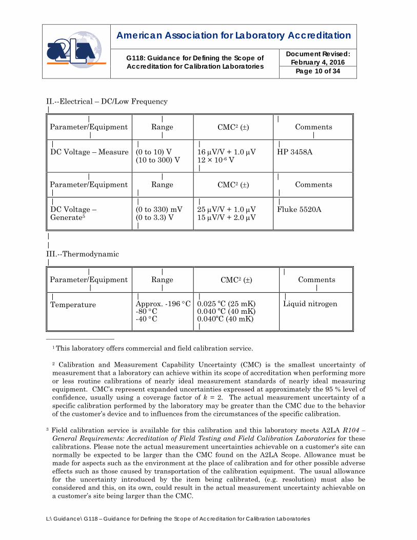
II.--Electrical – DC/Low Frequency |
| Parameter/Equipment
|
| Range
|
CMC2 (±)
| Comments
| | DC Voltage – Measure
| (0 to 10) V (10 to 300) V
| 16 µV/V + 1.0 µV 12 × 10-6 V |
| HP 3458A
| Parameter/Equipment |
| Range
|
CMC2 (±)
| Comments
| | DC Voltage – Generate5
| (0 to 330) mV (0 to 3.3) V |
| 25 µV/V + 1.0 µV 15 µV/V + 2.0 µV
| Fluke 5520A
| | III.--Thermodynamic |
| Parameter/Equipment
|
| Range
|
CMC2 (±)
| Comments
| | Temperature
| Approx. -196 °C -80 °C -40 °C
| 0.025 ºC (25 mK) 0.040 ºC (40 mK) 0.040ºC (40 mK) |
| Liquid nitrogen
____________________ 1 This laboratory offers commercial and field calibration service. 2 Calibration and Measurement Capability Uncertainty (CMC) is the smallest uncertainty of measurement that a laboratory can achieve within its scope of accreditation when performing more or less routine calibrations of nearly ideal measurement standards of nearly ideal measuring equipment. CMC’s represent expanded uncertainties expressed at approximately the 95 % level of confidence, usually using a coverage factor of k = 2. The actual measurement uncertainty of a specific calibration performed by the laboratory may be greater than the CMC due to the behavior of the customer’s device and to influences from the circumstances of the specific calibration.
3 Field calibration service is available for this calibration and this laboratory meets A2LA R104 – General Requirements: Accreditation of Field Testing and Field Calibration Laboratories for these calibrations. Please note the actual measurement uncertainties achievable on a customer's site can normally be expected to be larger than the CMC found on the A2LA Scope. Allowance must be made for aspects such as the environment at the place of calibration and for other possible adverse effects such as those caused by transportation of the calibration equipment. The usual allowance for the uncertainty introduced by the item being calibrated, (e.g. resolution) must also be considered and this, on its own, could result in the actual measurement uncertainty achievable on a customer’s site being larger than the CMC.

American Association for Laboratory Accreditation
G118: Guidance for Defining the Scope of Accreditation for Calibration Laboratories
Document Revised: February 4, 2016
Page 11 of 34
L:\Guidance\G118 – Guidance for Defining the Scope of Accreditation for Calibration Laboratories
4 In the statement of CMC, L is the numerical value of the nominal length of the gage block in inches, R is the numerical value of the resolution of the micrometer in micro inches, and D is the numerical value of the nominal diameter of the gage in inches.
5 The stated measured values are determined using the indicated instrument (see Comments). This capability is suitable for the calibration of the devices intended to measure or generate the measured value in the ranges indicated. CMC are expressed as either a specific value that covers the full range or as a fraction/percentage of the reading plus a fixed floor specification.
The CMCs on this example scope are not intended to be typical or representative or otherwise desirable uncertainties, they are shown merely for illustrative purposes.|
VIII. APPENDICES
APPENDIX A: Hardness Direct verification is calibration of each of the significant features of the testing machine and includes the force and depth indication. The verification of the dimensional features of the indenter is by direct measurement and by performance testing / indirect verification (for Rockwell only). Although repeatability and error are distinct measurands with generally different uncertainties, scopes of accreditation reference only the uncertainty of a single hardness measurement taken in the course of these verifications. Indirect Verification of Rockwell hardness The scope of accreditation for the indirect verification of Rockwell hardness testers includes the following information:
• the scales the lab is able to verify; • the CMC for a single hardness measurement; • reference to the indirect verification of Rockwell hardness testers by the method
of ASTM E18. • for each scale, three ranges are indicated (low, middle, and high) with
corresponding CMCs.
When indirectly verifying a portable tester, the ASTM document E110 is used. Care is taken to ensure the portable tester is not a comparative tester that electronically converts or uses charts to convert test values to hardness numbers. A tester can only meet E110 if it has the same test parameters as those specified in E10 and E18.

American Association for Laboratory Accreditation
G118: Guidance for Defining the Scope of Accreditation for Calibration Laboratories
Document Revised: February 4, 2016
Page 12 of 34
L:\Guidance\G118 – Guidance for Defining the Scope of Accreditation for Calibration Laboratories
Sample 1 - scope of accreditation for the indirect verification of Rockwell hardness testers.
Parameter/Equipment
Range CMC (±) Comments
Indirect Verification of Rockwell Hardness Testers
HRC:
Low Medium High
0.31 HRC 0.32 HRC 0.37 HRC
Indirect verification per ASTM E18
Parameter/Equipment
Range CMC (±) Comments
Indirection Verification of Superficial Hardness Testers
HRW:
Low Medium High
0.31 HRW 0.32 HRW 0.37 HRW
Indirect verification per ASTM E18
Notes:
1) There is no need to list the actual hardness values of the reference blocks (generic reference to the range is sufficient) since this creates an unnecessary need to update the scope of accreditation if new blocks are obtained. Only if the lab wishes to update the CMCs should it be necessary to revise the scope when new blocks are obtained.
Direct Verification for Rockwell hardness The scope of accreditation for the direct verification of Rockwell hardness testers contains the following information: Verification of the test force:
• the range of forces the lab can verify; • the associated CMC’s; • a reference to E4.
Note: At this point in time, the error component of force cannot be converted to hardness values. All hardness uncertainties are calculated using indirect verification from uncertainty annex shown in ASTM E18. Verification (direct) of the indenter (optional):
• the feature(s) measured; • its associated CMC.

American Association for Laboratory Accreditation
G118: Guidance for Defining the Scope of Accreditation for Calibration Laboratories
Document Revised: February 4, 2016
Page 13 of 34
L:\Guidance\G118 – Guidance for Defining the Scope of Accreditation for Calibration Laboratories
• where only a performance test for the indenter is made, the scope will simply note, “Indenters are verified only through the performance test.”
Carbide balls
• Hardness of the ball (using, ASTM E384 or ISO 6507 Vickers) • Geometry of the ball • Density of the ball
Note: All or some of the above may be determined by other laboratories if they are accredited.
Verification of the depth-measuring device.
• range of verification of the depth-measuring device; • the CMC; • the method of verification.
Note: In many cases, depth verification cannot be performed in the field because of tester incompatibilities. It may be necessary to list those types of testers which can be verified directly in the field.
If a laboratory is accredited for a partial direct verification, this fact is noted on the scope so that potential customers will know that an accredited, full direct verification is not available. Sample 2 - scope of accreditation for the direct verification of a Rockwell Hardness Tester
Parameter/Equipment
Range
CMC(±)
Comments
Direct Verification of Rockwell Hardness Testers -
Verification of the test force
Diamond indenter
Carbide ball indenter
150 kgf See E18, ISO 6507 Tip Radius Angle Straightness of the generatric line of the cone Hardness Radius
1.0 kgf 1.0 µm 0.10 degrees 1.0 µm 12 HV 1.0 µm
Direct verification method per ASTM E18 Verification of the test force is by load cell per the method of ASTM E4 The dimensional characteristics of the diamond indenter

American Association for Laboratory Accreditation
G118: Guidance for Defining the Scope of Accreditation for Calibration Laboratories
Document Revised: February 4, 2016
Page 14 of 34
L:\Guidance\G118 – Guidance for Defining the Scope of Accreditation for Calibration Laboratories
Verification of the depth-measuring device
Density (0 to 4) mm
0.10 gcm-3 0.30 µm
Notes:
1) Ranges need to be specified for the parameters of a direct verification. The nominal value of every feature is specified in E18.
2) CMCs are required for the verification of the force indication and verification of the depth-measuring device. If the dimensional characteristics of the diamond indenter are verified, then uncertainties need to be specified as well as measurement method, but no ranges.
Standardization of test blocks: Several features of standardized test blocks are specified in E18. The following features are considered to be trivially easy to verify and therefore do not warrant accreditation: block thickness, block surface area4, demagnetization. Sample 3 - scope of accreditation for the calibration of standardized Rockwell and Rockwell Superficial test blocks
Parameter/Equipment
Range
CMC(±)
Comments
Calibration of Standardized Rockwell Hardness and Rockwell Superficial Hardness Test Blocks:
Mean hardness value (HRC scale)
HRC:
Low Medium High
0.37 HRC 0.32 HRC 0.30 HRC
ASTM E18
Notes:
1) Verification of the dimensional characteristics of test blocks is not generally found on scopes of accreditation. In those cases, the scope should note that flatness, parallelism, and surface roughness are not verified and that the calibration is a limited calibration.
4 However, certificates for blocks that exceed the 4 in2 surface area limitation of E18 cannot bear the A2LA accredited symbol.

American Association for Laboratory Accreditation
G118: Guidance for Defining the Scope of Accreditation for Calibration Laboratories
Document Revised: February 4, 2016
Page 15 of 34
L:\Guidance\G118 – Guidance for Defining the Scope of Accreditation for Calibration Laboratories
2) If the block calibration laboratory is not in full compliance with the block geometry specifications of E18, that calibration will not be listed on the scope.
Indirect Verification of Vickers Hardness The scope of accreditation for the indirect verification of Vickers hardness testers includes the following information:
• levels of hardness for which the lab has standardized test blocks; • a reference to the indirect verification by the method of ASTM E384; • the CMC given in terms of HV.
Sample 4 - scope of accreditation for the indirect verification of Vickers hardness testers
Parameter/Equipment
Range
CMC(±)
Comments
Indirect Verification of Vickers Hardness Testers
(100 to 240) HV (>240 to 600) HV >600 HV
5.0 HV 8.0 HV 12 HV
Indirect verification per ASTM E384
Direct Verification of Vickers Hardness The scope of accreditation for the direct verification of Vickers hardness testers includes the following information:
1) Verification of the test force:
• the range of forces the lab can verify; • the associated CMC. • a reference to E4
2) Verification of the indenter.
Unlike Rockwell diamond indenters, E92 does not specify a performance test for Vickers indenters. Therefore, each of the dimensions specified in E92 must be checked either by direct measurement or by projection. These features are: a) angle between opposite faces of the pyramid; b) inclination of the four faces to the axis of the pyramid; c) junction of indenter faces for indenters used in routine testing; d) junction of indenter faces for indenters used for calibrating standardized test
blocks; e) angles of the quadrilateral formed by the intersection of the four faces of the
indenter with a plane perpendicular to the axis of the indenter.

American Association for Laboratory Accreditation
G118: Guidance for Defining the Scope of Accreditation for Calibration Laboratories
Document Revised: February 4, 2016
Page 16 of 34
L:\Guidance\G118 – Guidance for Defining the Scope of Accreditation for Calibration Laboratories
All laboratories wishing to be accredited for the direct verification of Vickers hardness testers are accredited for items a – c and e. Laboratories wishing to be accredited for the direct verification of Vickers hardness testers used for the calibration of standardized test blocks are accredited for at least items a, b, d, e or obtain from an accredited source a directly verified indenter.
3) Verification of the measuring microscope.
• the CMC; • an indication of the method of verification.
Laboratories that cannot perform each of these verifications are not normally be accredited for the direct verification of Vickers hardness testers. If a laboratory is accredited for a partial direct verification, this fact is noted on the scope so that potential customers will know that an accredited, full direct verification is not available. Sample 5 - scope of accreditation for the direct verification of a Vickers hardness tester
Parameter/Equipment
Range
CMC(±)
Comments
Direct Verification of Vickers Hardness Testers –
Verification of the test force Verification of the dimensional characteristics of the indenter:
Angle between opposite faces of the pyramid Inclination of the faces to the axis of the pyramid Junction of indenter faces for indenters used in routine testing
5 kgf
1.0 kgf 7.0’ 7.0’ 0.25 mm
Direct verification method per ASTM E92 Verification of the test force is by load cell per the method of ASTM E4 Verification of these dimensional features is by optical projection.

American Association for Laboratory Accreditation
G118: Guidance for Defining the Scope of Accreditation for Calibration Laboratories
Document Revised: February 4, 2016
Page 17 of 34
L:\Guidance\G118 – Guidance for Defining the Scope of Accreditation for Calibration Laboratories
Junction of indenter faces for indenters used for calibrating standardized test blocks Angles of the quadrilateral formed by the intersection of the four faces of the indenter with a plane perpendicular to the axis of the indenter
Verification of the device for measuring indentation diagonals
(0 to 200) µm
0.12 mm 3.0’ 0.28 µm
Notes:
1) Ranges need to be specified for the parameters of a direct verification except for force (since not every lab will necessarily be capable of verifying the entire force range). The nominal value of every other feature is specified in E92.
Standardization of test blocks: Several dimensional features of standardized test blocks are specified in E92 but the only non-trivial block geometry such as surface roughness, flatness and thickness are demonstrated. Sample 6 - scope of accreditation for the calibration of standardized Vickers test blocks
Parameter/Equipment
Range
CMC(±)
Comments
Calibration of Standardized Vickers Test Blocks
(100 to 240) HV (>240 to 600) HV >600 HV
4.0 HV 6.0 HV 10 HV
ASTM E384
Indirect Verification of Brinell Hardness The scope of accreditation for the indirect verification of Brinell hardness testers includes the following information:
• specification of each of the conditions the laboratory is accredited to verify; • a reference to the indirect verification by ASTM E10.
American Association for Laboratory Accreditation
G118: Guidance for Defining the Scope of Accreditation for Calibration Laboratories
Document Revised: February 4, 2016
Page 18 of 34
L:\Guidance\G118 – Guidance for Defining the Scope of Accreditation for Calibration Laboratories
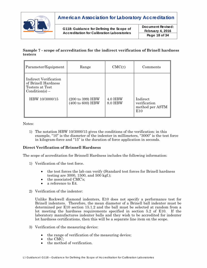
Sample 7 - scope of accreditation for the indirect verification of Brinell hardness testers
Parameter/Equipment
Range
CMC(±)
Comments
Indirect Verification of Brinell Hardness Testers at Test Condition(s) – HBW 10/3000/15
(200 to 399) HBW (400 to 600) HBW
4.0 HBW 8.0 HBW
Indirect verification method per ASTM E10
Notes:
1) The notation HBW 10/3000/15 gives the conditions of the verification: in this example, “10” is the diameter of the indenter in millimeters, “3000” is the test force in kilogram-force and “15” is the duration of force application in seconds.
Direct Verification of Brinnell Hardness The scope of accreditation for Brinnell Hardness includes the following information:
1) Verification of the test force.
• the test forces the lab can verify (Standard test forces for Brinell hardness testing are 3000, 1500, and 500 kgf.);
• the associated CMC’s; • a reference to E4.
2) Verification of the indenter:
Unlike Rockwell diamond indenters, E10 does not specify a performance test for Brinell indenters. Therefore, the mean diameter of a Brinell ball indenter must be determined per E10 section 15.1.2 and the ball must be selected at random from a lot meeting the hardness requirements specified in section 5.2 of E10. If the laboratory manufactures indenter balls and they wish to be accredited for indenter lot hardness certifications, then this will be a separate line item on the scope.
3) Verification of the measuring device:
• the range of verification of the measuring device; • the CMC; • the method of verification.
American Association for Laboratory Accreditation
G118: Guidance for Defining the Scope of Accreditation for Calibration Laboratories
Document Revised: February 4, 2016
Page 19 of 34
L:\Guidance\G118 – Guidance for Defining the Scope of Accreditation for Calibration Laboratories
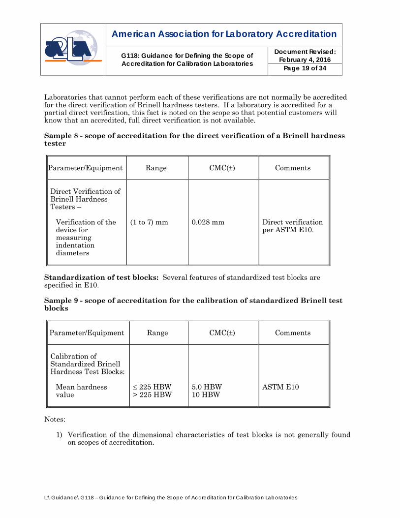
Laboratories that cannot perform each of these verifications are not normally be accredited for the direct verification of Brinell hardness testers. If a laboratory is accredited for a partial direct verification, this fact is noted on the scope so that potential customers will know that an accredited, full direct verification is not available. Sample 8 - scope of accreditation for the direct verification of a Brinell hardness tester
Parameter/Equipment
Range
CMC(±)
Comments
Direct Verification of Brinell Hardness Testers –
Verification of the device for measuring indentation diameters
(1 to 7) mm
0.028 mm
Direct verification per ASTM E10.
Standardization of test blocks: Several features of standardized test blocks are specified in E10. Sample 9 - scope of accreditation for the calibration of standardized Brinell test blocks
Parameter/Equipment
Range
CMC(±)
Comments
Calibration of Standardized Brinell Hardness Test Blocks:
Mean hardness value
≤ 225 HBW > 225 HBW
5.0 HBW 10 HBW
ASTM E10
Notes:
1) Verification of the dimensional characteristics of test blocks is not generally found on scopes of accreditation.

American Association for Laboratory Accreditation
G118: Guidance for Defining the Scope of Accreditation for Calibration Laboratories
Document Revised: February 4, 2016
Page 20 of 34
L:\Guidance\G118 – Guidance for Defining the Scope of Accreditation for Calibration Laboratories
Indirection Verification of Microindentation Hardness (Knoop and Vickers) The scope of accreditation for the indirect verification of microindentation hardness testers (Knoop and Vickers) includes the following information:
• levels of hardness for which the lab has standardized test blocks; • a reference to the indirect verification by the method of ASTM E384; • the CMC given in terms of HV or HK.
Sample 10 - scope of accreditation for the indirect verification of microindentation hardness testers
Parameter/Equipment
Range
CMC(±)
Comments
Indirect Verification of Microindentation Hardness Testers (Knoop and Vickers)
(100 to 250) HK (250 to 650) HK >650 HK
(100 to 240) HV
3.0 HK 8.0 HK 12 HK 7.0 HV
Indirect verification method per ASTM E384
Direct Verification of Microindentation Hardness (Knoop and Vickers) The scope of accreditation for the direct verification of microindentation hardness testers (Knoop and Vickers) includes the following information:
1) Verification of the indenter:
The features to be verified on the Vickers and Knoop indenters are:
a) Vickers: face angles, offset, inclination of the faces to the axis of the indenter. b) Knoop: indenter constant, included longitudinal edge angle, included
transverse edge angle, offset, inclination of the faces to the axis of the indenter.
2) Force verification:
• the range of forces the lab can verify; • associated CMC’s; • a reference to E4.
3) Measuring microscope verification:
• The CMC’s;
American Association for Laboratory Accreditation
G118: Guidance for Defining the Scope of Accreditation for Calibration Laboratories
Document Revised: February 4, 2016
Page 21 of 34
L:\Guidance\G118 – Guidance for Defining the Scope of Accreditation for Calibration Laboratories
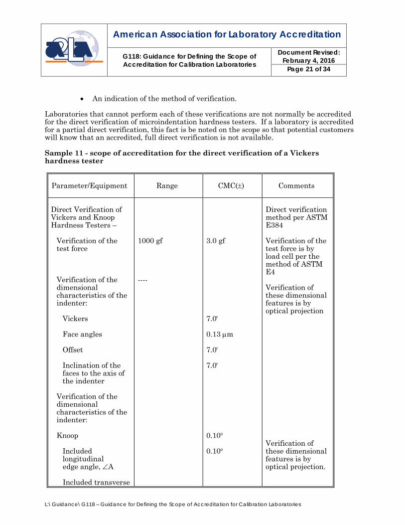
• An indication of the method of verification. Laboratories that cannot perform each of these verifications are not normally be accredited for the direct verification of microindentation hardness testers. If a laboratory is accredited for a partial direct verification, this fact is be noted on the scope so that potential customers will know that an accredited, full direct verification is not available. Sample 11 - scope of accreditation for the direct verification of a Vickers hardness tester
Parameter/Equipment
Range
CMC(±)
Comments
Direct Verification of Vickers and Knoop Hardness Testers –
Verification of the test force
Verification of the dimensional characteristics of the indenter:
Vickers Face angles Offset Inclination of the faces to the axis of the indenter
Verification of the dimensional characteristics of the indenter: Knoop
Included longitudinal
edge angle, ∠A Included transverse
1000 gf ----
3.0 gf 7.0′ 0.13 µm 7.0′ 7.0′ 0.10° 0.10°
Direct verification method per ASTM E384 Verification of the test force is by load cell per the method of ASTM E4 Verification of these dimensional features is by optical projection Verification of these dimensional features is by optical projection.
American Association for Laboratory Accreditation
G118: Guidance for Defining the Scope of Accreditation for Calibration Laboratories
Document Revised: February 4, 2016
Page 22 of 34
L:\Guidance\G118 – Guidance for Defining the Scope of Accreditation for Calibration Laboratories
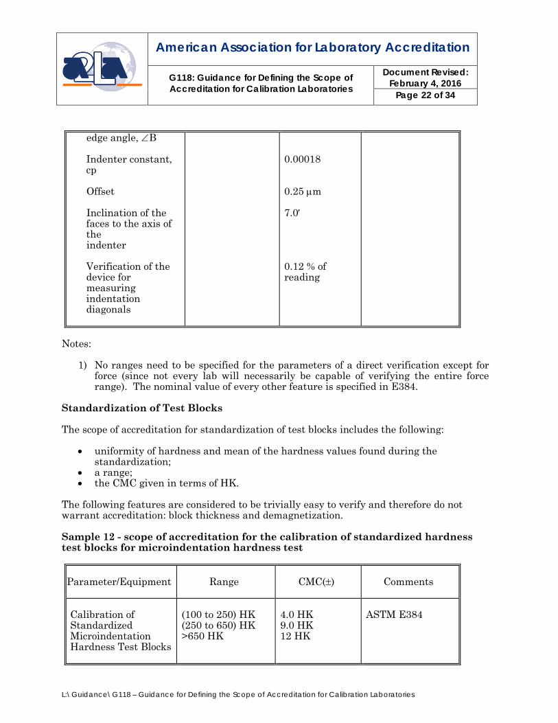
edge angle, ∠B
Indenter constant, cp
Offset Inclination of the
faces to the axis of the
indenter
Verification of the device for measuring indentation diagonals
0.00018 0.25 µm 7.0′ 0.12 % of reading
Notes:
1) No ranges need to be specified for the parameters of a direct verification except for force (since not every lab will necessarily be capable of verifying the entire force range). The nominal value of every other feature is specified in E384.
Standardization of Test Blocks The scope of accreditation for standardization of test blocks includes the following:
• uniformity of hardness and mean of the hardness values found during the standardization;
• a range; • the CMC given in terms of HK.
The following features are considered to be trivially easy to verify and therefore do not warrant accreditation: block thickness and demagnetization. Sample 12 - scope of accreditation for the calibration of standardized hardness test blocks for microindentation hardness test
Parameter/Equipment
Range
CMC(±)
Comments
Calibration of Standardized Microindentation Hardness Test Blocks
(100 to 250) HK (250 to 650) HK >650 HK
4.0 HK 9.0 HK 12 HK
ASTM E384
American Association for Laboratory Accreditation
G118: Guidance for Defining the Scope of Accreditation for Calibration Laboratories
Document Revised: February 4, 2016
Page 23 of 34
L:\Guidance\G118 – Guidance for Defining the Scope of Accreditation for Calibration Laboratories
APPENDIX B: Dimensional testing Some of the organizations accredited under the Mechanical field of testing for dimensional testing are actually performing calibration measurements as part (or all) of the measurements that they make. This situation is especially prevalent in dimensional measurement laboratories using coordinate measuring machine (CMMs) to perform their measurements. When the dimensional measurement laboratory is measuring what is commonly referred to as "hard tooling” or fixed gauges, there are times when that measured tool is going to be used by the laboratory's customer as the reference standard to measure their own parts. In those cases, the dimensional measurement laboratory is serving as a link in the traceability chain and is treated by A2LA and our assessors as a calibration laboratory. In these situations the requirements found in R205 – Specific Requirements: Calibration Laboratory Accreditation Program are applied in order to accredit the dimensional measurement organization for this service. It is understood that some of the dimensional measurements are performed as a small part of the mechanical scope or calibration scope of accreditation and that much of the work is taking measurements of automotive parts, for example, to ensure an appropriate fit on the automobile; this is considered dimensional testing. If a situation arises where a mechanical testing organization desires to include dimensional testing capability for which the unit under test does serve as link in the traceability chain on their scope of accreditation or a calibration organization desires to include dimensional testing capability for which the unit under test does not serve as link in the traceability chain, A2LA will accredit the organization without requiring them to hold a separate Scope of Accreditation. 1. For all dimensional testing parameters for which the unit under test does serve as link
in the traceability chain:
• The CAB meets the requirements of A2LA R205 - Specific Requirements: Calibration Laboratory Accreditation Program.
• A footnote identifying that the organization meets A2LA R205 - Specific Requirements: Calibration Laboratory Accreditation Program for the types of dimensional tests listed and is considered equivalent to that of a calibration is included in the scope of accreditation. Furthermore this is also identified on the test report.

American Association for Laboratory Accreditation
G118: Guidance for Defining the Scope of Accreditation for Calibration Laboratories
Document Revised: February 4, 2016
Page 24 of 34
L:\Guidance\G118 – Guidance for Defining the Scope of Accreditation for Calibration Laboratories
Example Mechanical Testing Scope or Calibration Scope presentation when the dimensional test does serve as a link in the traceability chain: I. Dimensional Testing/Calibration1
Parameter/Equipment
Range
CMC2, 4 (±)
Comments
One Dimensional3 –
Length Radius
Up to 6 in Up to 6 in
0.32 millinch 0.28 millinch
Optical comparator
Length Standards (1D)3
(0.01 to 25) in
(75 + 2.0L) μin
CMM
___________________________________________________________ 1 This laboratory offers commercial dimensional testing/calibration service. 2 Calibration and Measurement Capability Uncertainty (CMC) is the smallest uncertainty of measurement that a laboratory can achieve within its scope of accreditation when performing more or less routine calibrations of nearly ideal measurement standards or nearly ideal measuring equipment. CMC’s represent expanded uncertainties expressed at approximately the 95 % level of confidence, usually using a coverage factor of k = 2. The actual measurement uncertainty of a specific calibration performed by the laboratory may be greater than the CMC due to the behavior of the customer’s device and to influences from the circumstances of the specific calibration.
3 This laboratory meets R205 – Specific Requirements: Calibration Laboratory Accreditation Program for the types of dimensional tests listed above and is considered equivalent to that of a calibration. 4 In the statement of CMC, L is the numerical value of the nominal length of the device expressed in inches.
American Association for Laboratory Accreditation
G118: Guidance for Defining the Scope of Accreditation for Calibration Laboratories
Document Revised: February 4, 2016
Page 25 of 34
L:\Guidance\G118 – Guidance for Defining the Scope of Accreditation for Calibration Laboratories
2. For all dimensional testing parameters for which the unit under test does not serve as link in the traceability chain the following applies for the presentation of the scope:
• The parameter, range, and Technique and/or Test Method (Standard) are
identified on the scope (3 column scope).
• Units for Angle measurements degrees, minutes and seconds, use the following corresponding symbols: °, ’, ’’
• Normally the range cannot begin with zero. Instead “Up to” or a number greater than zero is used.
• For Parameters, each word is capitalized.
• For Techniques, only first word is capitalized.
• For the process of rounding, the usual rules for rounding of numbers shall be used, subject to the guidance on rounding provided i.e in Section 7 of the GUM5.
• The following footnote is included in the scope of accreditation “This test is not equivalent to that of a calibration.” Furthermore, this is also identified in the test report.
• Use of the term “length” requires a qualifier.
5 Evaluation of measurement data – Guide to the expression of uncertainty in measurement JCGM 100:2008 (GUM 1995 with minor corrections).
American Association for Laboratory Accreditation
G118: Guidance for Defining the Scope of Accreditation for Calibration Laboratories
Document Revised: February 4, 2016
Page 26 of 34
L:\Guidance\G118 – Guidance for Defining the Scope of Accreditation for Calibration Laboratories
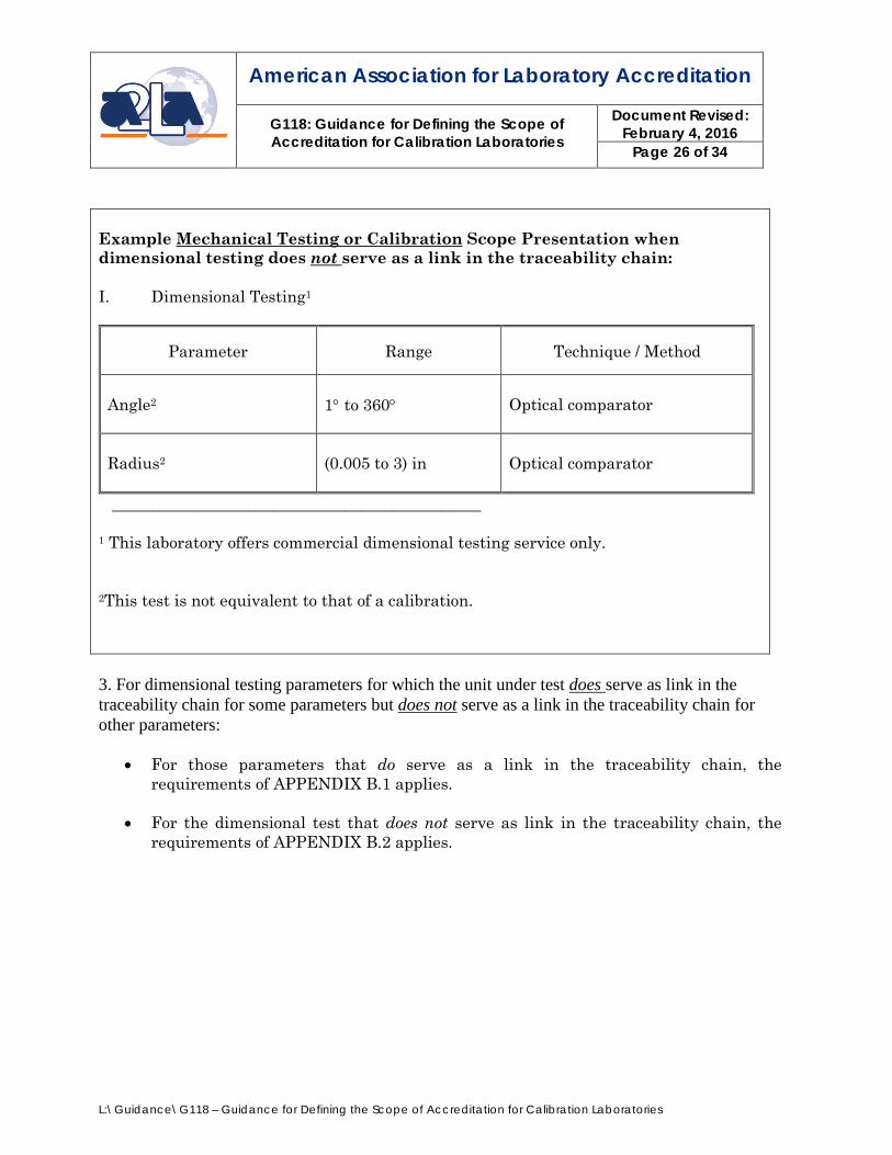
Example Mechanical Testing or Calibration Scope Presentation when dimensional testing does not serve as a link in the traceability chain: I. Dimensional Testing1
Parameter Range Technique / Method
Angle2
1° to 360°
Optical comparator
Radius2
(0.005 to 3) in
Optical comparator
______________________________________________ 1 This laboratory offers commercial dimensional testing service only.
2This test is not equivalent to that of a calibration.
3. For dimensional testing parameters for which the unit under test does serve as link in the traceability chain for some parameters but does not serve as a link in the traceability chain for other parameters:
• For those parameters that do serve as a link in the traceability chain, the
requirements of APPENDIX B.1 applies.
• For the dimensional test that does not serve as link in the traceability chain, the requirements of APPENDIX B.2 applies.

American Association for Laboratory Accreditation
G118: Guidance for Defining the Scope of Accreditation for Calibration Laboratories
Document Revised: February 4, 2016
Page 27 of 34
L:\Guidance\G118 – Guidance for Defining the Scope of Accreditation for Calibration Laboratories
Example Scope Presentation when dimensional testing does and does not serve as a link in the traceability chain: I. Dimensional Testing/Calibration1
Parameter/Equipment
Range
CMC2 (±)
Comments
Length Standards (1D)3
Up to 25 in
(75 + 2.0L) μin
CMM
Gridplates (2D)3
(6 x 8) in
(60 + 5.0L) μin
Vision CMM
Fixture Gages (3D)3
(20 x 25 x 15) in
(200 + 5.0L) μin
CMM
II. Dimensional Testing4
Parameter Range Technique/ Method
Angle5
1° to 360°
Optical comparator
Workpiece Measurement5
1D 2D 3D 1D 2D
Up to 25 in (20 x 25) in (20 x 25 x 15) in Up to 8 in (6 x 8) in
CMM CMM CMM Vision CMM Vision CMM
___________________________________________________________ 1 This laboratory offers commercial dimensional testing/calibration service. 2 Calibration and Measurement Capability Uncertainty (CMC) is the smallest
American Association for Laboratory Accreditation
G118: Guidance for Defining the Scope of Accreditation for Calibration Laboratories
Document Revised: February 4, 2016
Page 28 of 34
L:\Guidance\G118 – Guidance for Defining the Scope of Accreditation for Calibration Laboratories
uncertainty of measurement that a laboratory can achieve within its scope of accreditation when performing more or less routine calibrations of nearly ideal measurement standards or nearly ideal measuring equipment. CMC’s represent expanded uncertainties expressed at approximately the 95 % level of confidence, usually using a coverage factor of k = 2. The actual measurement uncertainty of a specific calibration performed by the laboratory may be greater than the CMC due to the behavior of the customer’s device and to influences from the circumstances of the specific calibration. 3 This laboratory meets R205 – Specific Requirements: Calibration Laboratory Accreditation Program for the types of dimensional tests listed above and is considered equivalent to that of a calibration. Note: This footnote must be identified with a parameter. 4 This laboratory offers commercial dimensional testing service only. 5 This test is not equivalent to that of a calibration. Note: This footnote must be identified with a parameter. 6 In the statement of CMC, L is the numerical value of the nominal length of the device measured in inches.
American Association for Laboratory Accreditation
G118: Guidance for Defining the Scope of Accreditation for Calibration Laboratories
Document Revised: February 4, 2016
Page 29 of 34
L:\Guidance\G118 – Guidance for Defining the Scope of Accreditation for Calibration Laboratories
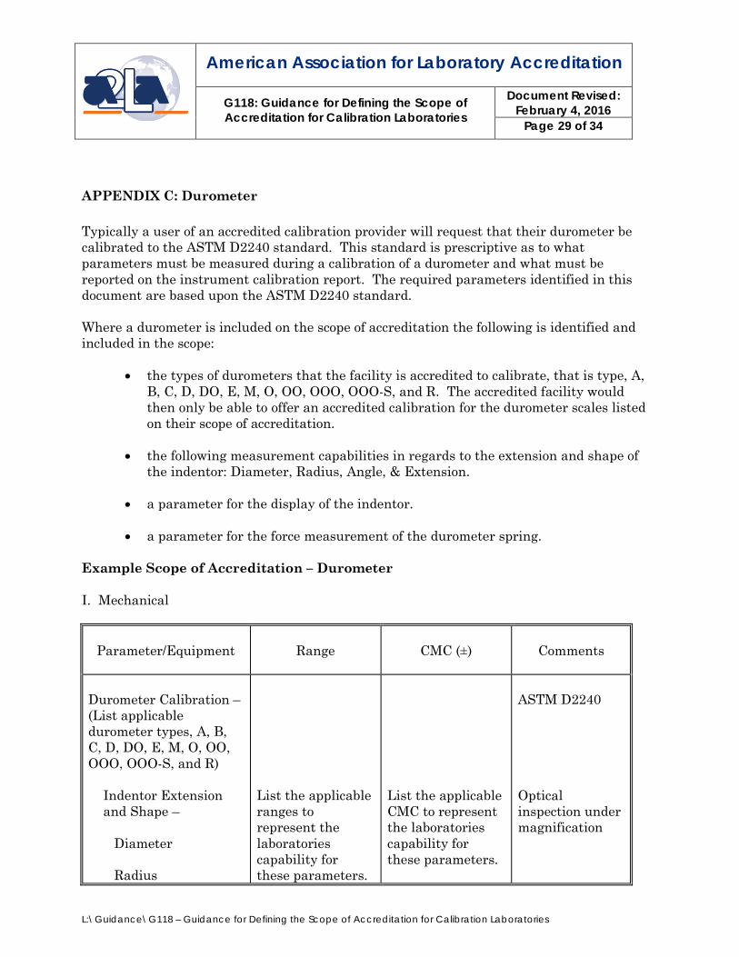
APPENDIX C: Durometer Typically a user of an accredited calibration provider will request that their durometer be calibrated to the ASTM D2240 standard. This standard is prescriptive as to what parameters must be measured during a calibration of a durometer and what must be reported on the instrument calibration report. The required parameters identified in this document are based upon the ASTM D2240 standard. Where a durometer is included on the scope of accreditation the following is identified and included in the scope:
• the types of durometers that the facility is accredited to calibrate, that is type, A, B, C, D, DO, E, M, O, OO, OOO, OOO-S, and R. The accredited facility would then only be able to offer an accredited calibration for the durometer scales listed on their scope of accreditation.
• the following measurement capabilities in regards to the extension and shape of
the indentor: Diameter, Radius, Angle, & Extension. • a parameter for the display of the indentor. • a parameter for the force measurement of the durometer spring.
Example Scope of Accreditation – Durometer I. Mechanical
Parameter/Equipment
Range
CMC (±)
Comments
Durometer Calibration – (List applicable durometer types, A, B, C, D, DO, E, M, O, OO, OOO, OOO-S, and R)
Indentor Extension and Shape –
Diameter Radius
List the applicable ranges to represent the laboratories capability for these parameters.
List the applicable CMC to represent the laboratories capability for these parameters.
ASTM D2240 Optical inspection under magnification
American Association for Laboratory Accreditation
G118: Guidance for Defining the Scope of Accreditation for Calibration Laboratories
Document Revised: February 4, 2016
Page 30 of 34
L:\Guidance\G118 – Guidance for Defining the Scope of Accreditation for Calibration Laboratories
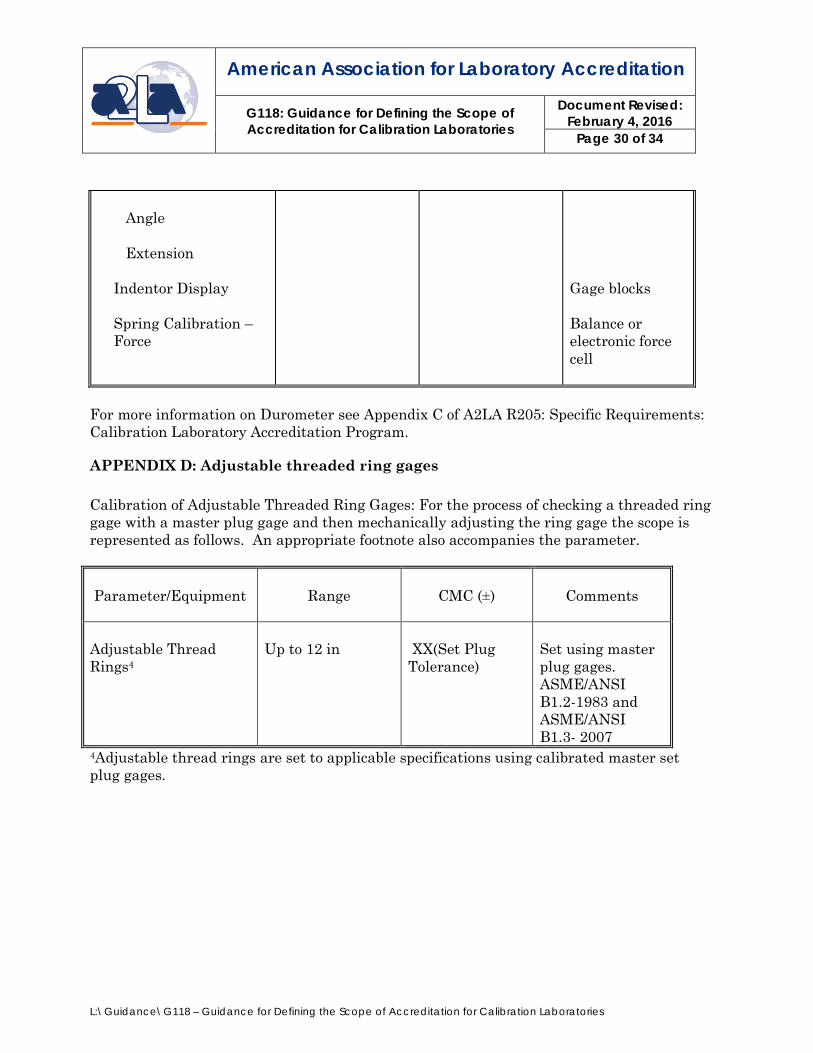
Angle Extension
Indentor Display
Spring Calibration – Force
Gage blocks Balance or electronic force cell
For more information on Durometer see Appendix C of A2LA R205: Specific Requirements: Calibration Laboratory Accreditation Program.
APPENDIX D: Adjustable threaded ring gages Calibration of Adjustable Threaded Ring Gages: For the process of checking a threaded ring gage with a master plug gage and then mechanically adjusting the ring gage the scope is represented as follows. An appropriate footnote also accompanies the parameter.
Parameter/Equipment
Range
CMC (±)
Comments
Adjustable Thread Rings4
Up to 12 in
XX(Set Plug Tolerance)
Set using master plug gages. ASME/ANSI B1.2-1983 and ASME/ANSI B1.3- 2007
4Adjustable thread rings are set to applicable specifications using calibrated master set plug gages.

American Association for Laboratory Accreditation
G118: Guidance for Defining the Scope of Accreditation for Calibration Laboratories
Document Revised: February 4, 2016
Page 31 of 34
L:\Guidance\G118 – Guidance for Defining the Scope of Accreditation for Calibration Laboratories
IX. Definitions For the purpose of these Requirements, the relevant terms and definitions given in ISO/IEC 17000 and the VIM apply. General definitions related to quality are given in Q9000, whereas ISO/IEC 17000 gives definitions specifically related to standardization, certification and laboratory accreditation. Where different definitions are given in Q9000, the definitions in ISO/IEC 17000 and VIM are preferred. Best Existing Device6: is defined as a device to be calibrated that is commercially or otherwise available for customers, even if it has a special performance (stability) or has a long history of calibration. Calibration and Measurement Capability Uncertainty (CMC)7: a CMC is a calibration and measurement capability available to customers under normal conditions:
a) as described in the laboratory’s scope of accreditation granted by a signatory to the ILAC Arrangement; or
b) as published in the BIPM8 key comparison database (KCDB) of the CIPM MRA9.
Conformity Assessment Body (CAB): a body that performs conformity assessment services and that can be the object of accreditation. Note: Whenever the word “CAB” is used, it applies to both the applicant and accredited CABs unless otherwise specified. Measurement Uncertainty: “Measurement uncertainty” refers to the measurement uncertainty calculation developed to demonstrate how the claimed Calibration and Measurement Capability (CMC) was derived for the scope of accreditation. It does not refer to the measurement uncertainty calculated as part of the measurement as reported on a calibration certificate.
It is further understood to mean “expanded uncertainty”, as defined in the GUM, expressed at approximately the 95 % level of confidence using a coverage factor of k = 2.
6 Adapted from ILAC P14:01/2013 ILAC Policy for Uncertainty in Calibration 7 Per the CIPM MRA-D-04, Calibration and Measurement Capabilities in the context of the CIPM MRA, Version 4 October 2013. 8 For the BIPM KCDB see http://kcdb.bipm.org/AppendixC/country_list_search.asp?page=1&pge=4&CountSelected=US&type=T 9 For the CIPM MRA see http://www.bipm.org/en/cipm-mra/

American Association for Laboratory Accreditation
G118: Guidance for Defining the Scope of Accreditation for Calibration Laboratories
Document Revised: February 4, 2016
Page 32 of 34
L:\Guidance\G118 – Guidance for Defining the Scope of Accreditation for Calibration Laboratories
Metrological Traceability10: property of a measurement result whereby the result can be related to a reference through a documented unbroken chain of calibrations, each contributing to the measurement uncertainty. X. References R105 - Requirements When Making Reference to A2LA Accredited Status P102 - A2LA Policy on Metrological Traceability P109 - Technical Consensus Decisions from the Measurement Advisory Committee (MAC) R101 - General Requirements: Accreditation of ISO/IEC 17025 Laboratories R103 - General Requirements: Proficiency Testing for ISO/IEC 17025 Laboratories - 2013 R104 - General Requirements: Accreditation of Field Testing and Field Calibration
Laboratories APLAC TC 004 12/06: Method of Stating Test and Calibration Results and Compliance with Specifications ANSI/ISO/ASQ Q9000:2000, Quality management systems – Fundamentals and vocabulary. ANSI/NCSL Z540-1-1994, Part I, Calibration Laboratories and Measuring and Test Equipment- General Requirements. ANSI/NCSL Z540-2-1997, U.S. Guide to the Expression of Uncertainty in Measurement. BIPM JCGM 200:2012, International vocabulary of metrology - Basic and general concepts and associated (VIM) 3rd edition (2008 version with minor corrections). CIPM MRA-D-04, Calibration and Measurement Capabilities in the context of the CIPM MRA Version 4 October 2013 BIPM JCGM 100:2008, Evaluation of measurement data – Guide to the expression of uncertainty in measurement (GUM 1995 with minor corrections). ILAC-P8:07/2006, ILAC Mutual Recognition Arrangement (Arrangement): Supplementary Requirements and Guidelines for the Use of Accreditation Symbols and for Claims of Accreditation Status by Accredited Laboratories 10 Per JCGM 200:2012 International vocabulary of metrology – Basic and general concepts and associated terms (VIM) 3rd edition.

American Association for Laboratory Accreditation
G118: Guidance for Defining the Scope of Accreditation for Calibration Laboratories
Document Revised: February 4, 2016
Page 33 of 34
L:\Guidance\G118 – Guidance for Defining the Scope of Accreditation for Calibration Laboratories
ILAC P10:01/2013, ILAC Policy on Traceability of Measurement Results. ILAC P14:01/2013 ILAC Policy for Uncertainty in Calibration ILAC G8:03/2009, Guidelines on Assessment and Reporting of Compliance with Specification. ISO/IEC 17025:2005, General requirements for the competence of testing and calibration laboratories. ISO/IEC 17000: Conformity assessment – Vocabulary and general principles. ISO/IEC 17043:2010 - Conformity assessment -- General requirements for proficiency testing. NIST Technical Note 1297, Guidelines for Evaluating and Expressing the Uncertainty of NIST Measurement Results, Taylor, Barry N., Kuyatt, Chris E., U.S. Government Printing Office, Washington, D.C., 1993. UKAS, The Expression of Uncertainty and Confidence in Measurement (M3003), 2007. ANSI/NCSL Z540.3-2006, Sub-clause 5.3, Requirements for the Calibration of Measuring and Test Equipment.
American Association for Laboratory Accreditation
G118: Guidance for Defining the Scope of Accreditation for Calibration Laboratories
Document Revised: February 4, 2016
Page 34 of 34
L:\Guidance\G118 – Guidance for Defining the Scope of Accreditation for Calibration Laboratories
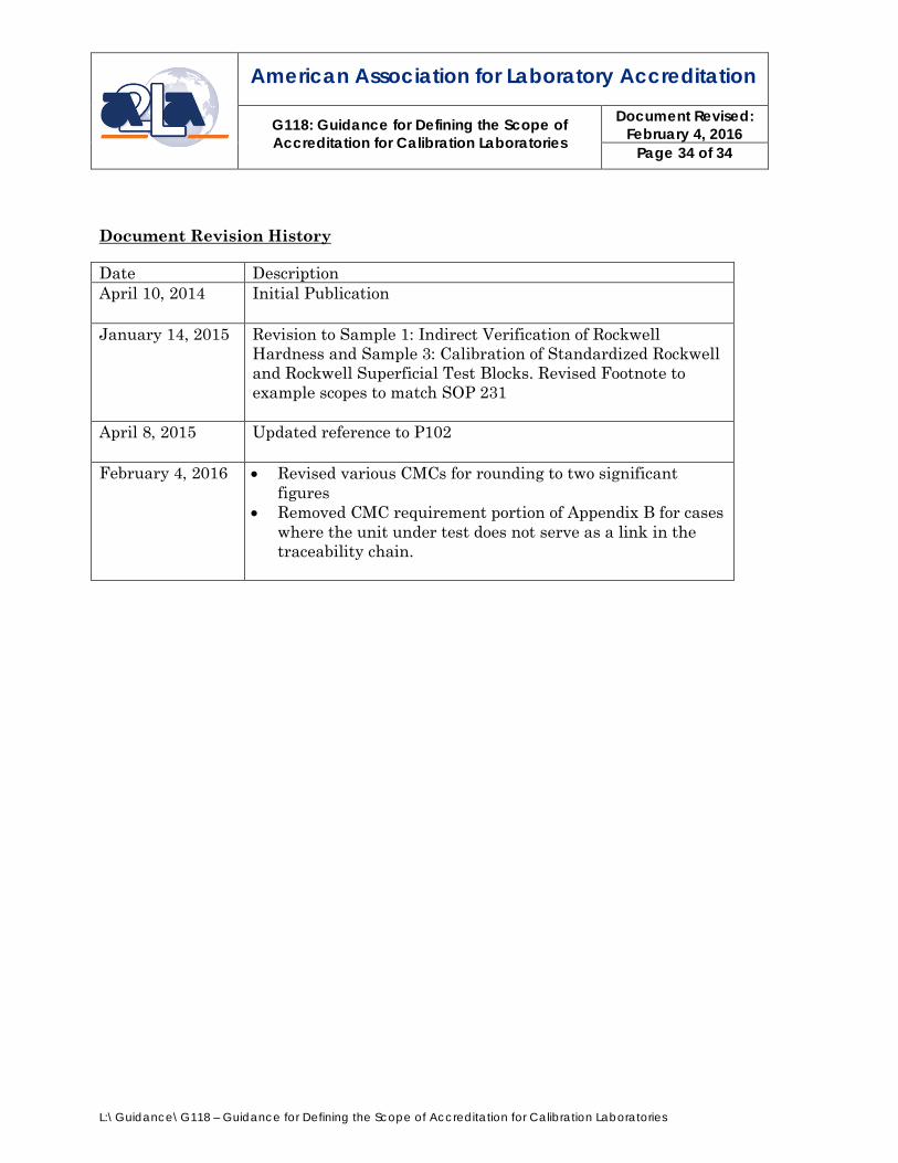
Document Revision History Date Description April 10, 2014 Initial Publication
January 14, 2015 Revision to Sample 1: Indirect Verification of Rockwell
Hardness and Sample 3: Calibration of Standardized Rockwell and Rockwell Superficial Test Blocks. Revised Footnote to example scopes to match SOP 231
April 8, 2015 Updated reference to P102
February 4, 2016 • Revised various CMCs for rounding to two significant figures
• Removed CMC requirement portion of Appendix B for cases where the unit under test does not serve as a link in the traceability chain.