amer sassila_portfolio (iit works)
TRANSCRIPT

Amer SassilaArchitectural Portfolio

Table of ContentsEntrepreneurship Academy- Building Information- Site Infl uence on Building Design- Priorities- Plans and Building Geometry- Sections and Elevations- Sustainability Strategies: -Double Envelope and Cross Ventilation -Double Envelope, Stack Effect, Thermal Lag -Glare Mitigation with Wood Slat Pattern on Facade- Material Selection for Thermal Resistance- Calculations - Heating - Cooling, Electrical, and Plumbing Fixtures Count- Systems Path Throughout the Building- Process Work and Final Physical ModelP-Chord Market- Building Information- Site Information- Orthographic Drawings- Detailed Section- Extensive Roof Filtration System- Aquaponic and Indoor Garden Diagrams- Climate Analysis- Passive Heating Strategies- Passive Cooling Strategies- Process Work and Final Physical ModelPompidou Centre Structural Analysis Model- Summary- Stress Gradient (East Side)- Stress Gradient (North Side)- Theoretical Calculation of the Vertical Loads, Reactions, Shear and Moment on the Structure- Theoretical Calculation of the Vertical Loads, Reactions, Shear and Moment on the Structure- Reference Plan- The Physical Model

Entrepreneurship Academy
Statement of IntentThe main objective of this design is to create an Entrepreneurship Acad-emy that encourages its pupilsto interact with each other, with the insti-tution’s neighboring Maker’s Institution, and with Uptown. The purpose of this objective is to provide spaces that encourages its occupants to become proactive,engaging and successful in their endeavors. To do so, we provide the offi ce sector as the mainprogram that works like a womb for ideas. The education sector is the source of growth of the ideas,like a booster or catalyst. Additional supporting program including lobby space to welcome people of all backgrounds in open arms, commercial space, recreational space for multipurpose use, residential space, and the new-ly designed Clifton Avenue Plaza that serves to encourage entrepreneur-ship and unite the surrounding institutions while simultaneously providing an iconic identity to the Uptown neighborhood.
Floor Area Work/Education Space - Level 1- Commercial Space (1 unit) = 1620 ft2
- Lobby Space (Institution) = 6044 ft2
- Lobby Space (Residential) = 840 ft2
Total Area = 6,884 ft2
Work/Education Space - Level 2- Open Offi ce Space = 11,688 ft2
- Education Space (classrooms included) = 7844 ft2
Total Area = 19,532 ft2
Work/Education Space - Level 3- Open Offi ce Space = 11,688 ft2
- Education Space (classrooms included) = 5224 ft2
Total Area = 16,912 ft2
Work/Education Space - Level 4- Open Offi ce Space = 11,688 ft2
- Education Space (classrooms included) = 5944 ft2
Total Area = 17,632 ft2
Auditorium (per 1 quantity) = 2400 ft2
Residential Recreation Floor (Level 5) = 9350 ft2
Residential Unit East = 807 ft2
Residential Unit West = 711 ft2
Residential Unit SW/SE = 625 ft2
Residential Unit NE = 945 ft2
Residential Unit NW = 810 ft2
Wall Area (Transparent = T , Opaque = O)- Commercial Space = 3240 ft2 (T), 3240 ft2 (O)- Education Space = 15,530 ft2 (T), 2678 ft2 (O)- Work Space = 14,616 ft2 (T), 1080 ft2 (O)- Residential Lobby = 1065 ft2 (T), 213 ft2 (O)- Education Space = 14,616 ft2 (T), 1080 ft2 (O)- Residential Unit East = 240 ft2 (T), 830 ft2 (O)- Residential Unit West = 240 ft2 (T), 750 ft2 (O)- Residential Unit SW/SE = 500 ft2 (T), 500 ft2 (O)- Residential Unit NE = 620 ft2 (T), 620 ft2 (O)- Residential Unit NW = 570 ft2 (T), 570 ft2 (O)
Building Information
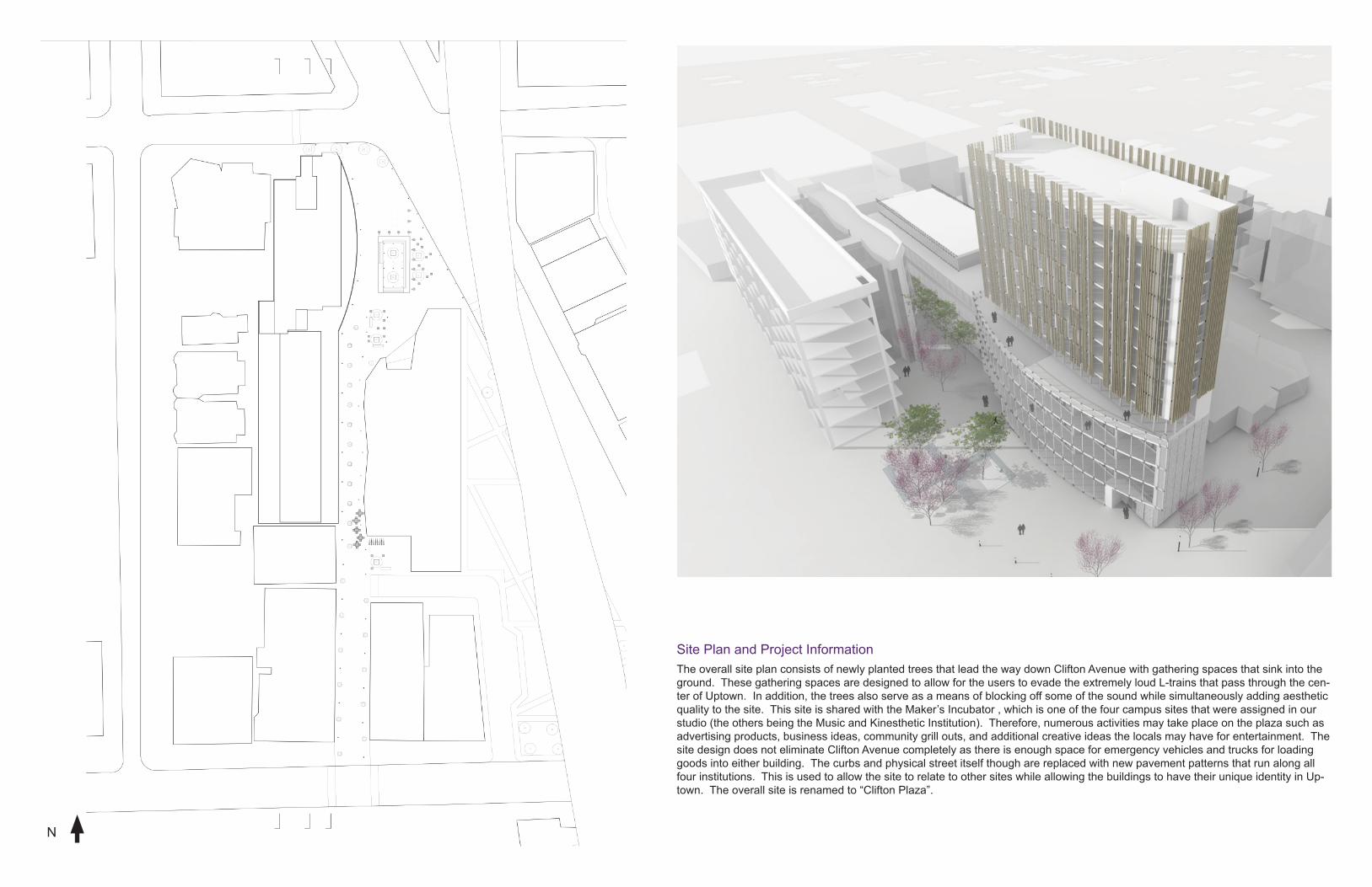
Site Plan and Project InformationThe overall site plan consists of newly planted trees that lead the way down Clifton Avenue with gathering spaces that sink into the ground. These gathering spaces are designed to allow for the users to evade the extremely loud L-trains that pass through the cen-ter of Uptown. In addition, the trees also serve as a means of blocking off some of the sound while simultaneously adding aesthetic quality to the site. This site is shared with the Maker’s Incubator , which is one of the four campus sites that were assigned in our studio (the others being the Music and Kinesthetic Institution). Therefore, numerous activities may take place on the plaza such as advertising products, business ideas, community grill outs, and additional creative ideas the locals may have for entertainment. The site design does not eliminate Clifton Avenue completely as there is enough space for emergency vehicles and trucks for loading goods into either building. The curbs and physical street itself though are replaced with new pavement patterns that run along all four institutions. This is used to allow the site to relate to other sites while allowing the buildings to have their unique identity in Up-town. The overall site is renamed to “Clifton Plaza”.
N

Site Infl uence on Building Design
Site InformationThe site is located in Uptown on the north side of the city of Chicago. The surrounding sites outside the overall Uptown context consist of Lincoln Square, Lakeview, Sheridan Park, and Little Vietnam. The region used to be the home of theatre production before Hollywood. Remnants of the theatre remain when experiencing Uptown through series of facades that are shaped with well crafted classical ornaments. Key markers in the area are the Aragon Ballroom, the Uptown Theatre, the Riviera Theatre, Green Mill Cocktail Lounge, the Arcadia Ballroom and numerous types of restaurants on Broad-way. All these theatres and restaurants indicate a lively nightlife of the area, producing a lot of noise in the area. In addition to the loud and lively music is the CTA Redline L-train path that cuts right through Uptown.
Overlap of Major Program
Sunlight Exposure
Sound Level
Public vs. Private

Inspiring and Toasty Spaces - to provide comfort to the users and visitors
Gathering and Overlapping Spaces - one space is for all
Welcoming Entrance - greeting people with the design
Priorities
1.) Inspiring and Toasty Spaces
2.) Gathering and Overlapping Spaces
3.) Welcoming Entrances
4.) Relating to the Other Institutions on Campus
5.) Enterprising

Relating to Other Institutions on Campus - Clifton Plaza with the Maker’s Incubator
Enterprising - using the Residential as a means of affordable Housing and Real Estate for the neighborhood.
Priorities
1.) Inspiring and Toasty Spaces
2.) Gathering and Overlapping Spaces
3.) Welcoming Entrances
4.) Relating to the Other Institutions on Campus
5.) Enterprising

Building Plans and Geometry
N
B1
Parking Ramp 1Parking Spaces 2Auditorium 3Convention Space 4Bookstore 5Telecommunication 6Fire Control Room 7Restrooms 8Residential Elevator 9Institution Elevator 10MEP Room 11
L1
Institution Entrance 1Residential Entrance 2Grand Staircase 3Coffee Shop 4Leisure/Study Space 5Commercial Units 6Security Room 7Residential Elevator 8Institution Elevator 9Fire Exits 10
L2
Classrooms 1Offi ces 2Conference Rooms 3Administration Offi ces 4Library Commons 5Grand Staircase 6Residential Elevator 7Institution Elevator 8Restrooms 9Fire Exits 10MEP Room 11
L6 - L13
Typical Unit East 1Typical Unit West 2Southeast Unit 3Southwest Unit 4Northeast Unit 5Northwest Unit 6Residential Elevator 7Fire Exits 8
L3 - L4
Classrooms 1Offi ces 2Conference Rooms 3Administration Offi ces 4Grand Staircase 5Residential Elevator 6Institution Elevator 7Restrooms 8Fire Exits 9MEP Room 10
L5
Recreation Garden 1Residential Elevator 2Fire Exits 3Outdoor Terrace 4
B1
L1
L2
L3
L4
L5
L6 - L13
1
2
3
4
3
5
6 7
8 811
10 9
12
43
5
6
7
8
10
96666610
10
1
24
35
6 78
10
9
1010 33
2 2 2 2 2
2 2 2 2 2 2
1 1
1
24
3
5 67
8
9
33
2 2 2 2 2
2 2 2 2 2 2
1 111
9
99
8
1
24
3
5 67
8
9
33
2 2 2 2 2
2 2 2 2 2 2
1 111
99
8
1
11
10
10
12
3
3
4
1 1 1 1
2 2 2 2
3
4
5
6
78
8

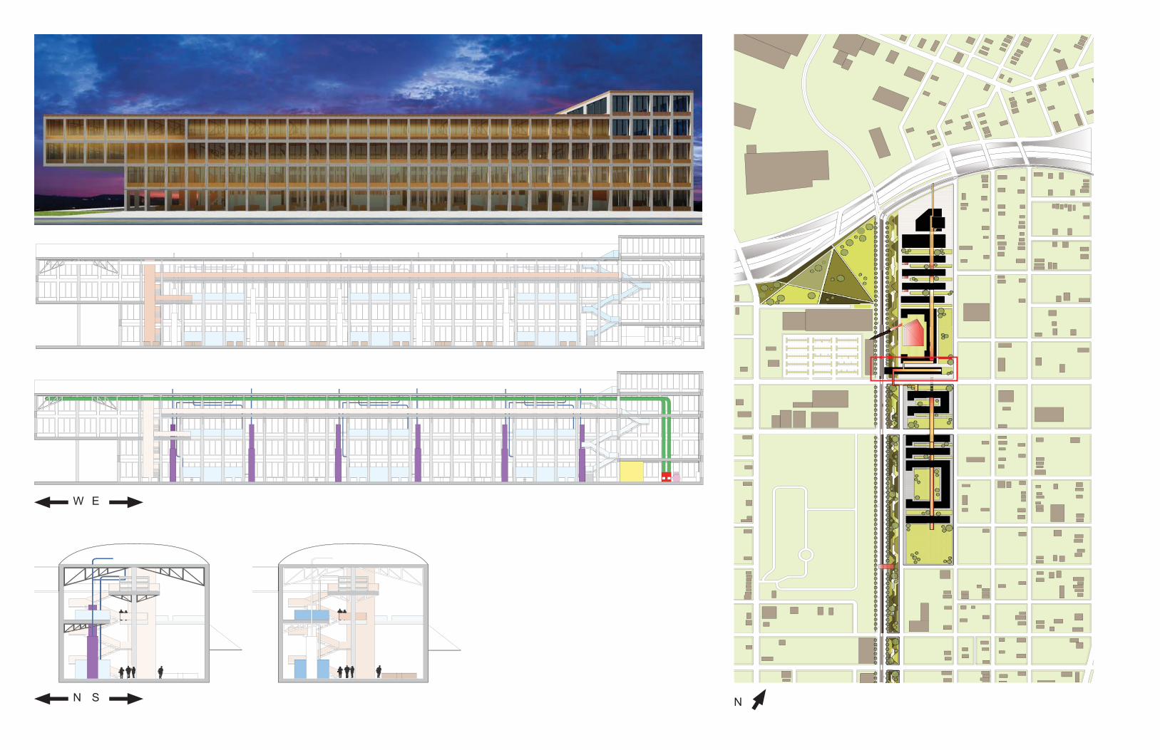
Sections and Elevations
NS
NS
EW
SN
WE

Sustainability Strategy: Double Envelope and Cross-Ventilation
Double Glass EnvelopeThe purpose of the double glass facade is to allow for cross ventilation during any season of work. In addition, because the air traveling through will be closer to room temperature due to being barricading the wind chill, the double glass envelope will enable the building to use less energy to heat the space. This will be because the change in temperature from facade to space will be less.

Sustainability Strategy: Double Envelope, Stack Effect, Thermal Lag
Stack Effect Enabling the stack effect in the institution will allow for further energy reduction especially during the winter hours. Although glass has an extremely low R-value, the radiant heat generated from the sunlight will allow opaque material inside to absorb the radiant ener-gy. Through thermal lag, the heat rises to the top, resulting to the stack effect in which the windows in the atriums of the institution will open to exhaust the air. When the forecast indicates no sunlight, at the very least the double glass facade can still keep the tempera-ture change less.

Sustainability Strategy: Glare Mitigation with Wood Slat Pattern on Facade
Wood SlatsThe slats not only allow for beautiful aesthetic covering of the building, but also function to mitigate glare for the residents when the sun is on the east and west. Wooden slats were selected to indicate architectural innovation as a theme for the institution. This is because there is the typical brick, steel, concrete and glass fa-cades that exist all around Chicago. The wood gives the space a unique identity to Uptown as well as to the city. These slats are not structural and are bolted to the concrete facade.

Commercial Walls- Double Pane Glazing w/ Thermal Break Aluminum Frame w/ Low -e coat = 0.51 U- Aluminum Metal Panel = 1 R- CMU Wall = 2 R- Cellular Polyisocyanurate (CFC) Insulation Board = 7.04 R/inch- Film = 0.1 R
Education Walls- Double Pane Glazing w/ Thermal Break Aluminum Frame w/ Low -e coat = 0.51 U- Single Pane 1/4” thick Acrylic Aluminum Frame (2nd Layer of Double Skin) = 0.96 U- Aluminum Metal covering of Base = 1 R- Cellular Polyisocyanurate (CFC) Insulation Board = 7.04 R/inch
Offi ce Walls- Double Pane Glazing w/ Thermal Break Aluminum Frame w/ Low -e coat = 0.51 U- Single Pane 1/4” thick Acrylic Aluminum Frame (2nd Layer of Double Skin) = 0.96 U- Aluminum Metal covering of Base = 1 R- Cellular Polyisocyanurate (CFC) Insulation Board = 7.04 R/inch
Residential Walls- Double Pane Glazing w/ Thermal Break Aluminum Frame w/ Low -e coat = 0.51 U- Single Pane 1/4” thick Acrylic Aluminum Frame (operable window) = 0.96 U- Hem Fir Wood Slats = 1.35 R/inch- Cement Fiber Board Panels (Shredded Wood w/ Portland Cement = 2 R- Vapor Barrier = 0.1 R- Cellular Polyisocyanurate (CFC) Insulation Board = 7.04 R/inch
Roof- 8” thick Concrete Slab = (0.1 R/inch)- Cellular Polyisocyanurate (CFC) Insulation Board = 7.04 R/inch- Vapor Barrier = 0.1 R
Auditorium- 12” thick Concrete Slab = (0.1 R/inch)- Cellular Polyisocyanurate (CFC) Insulation Board = 7.04 R/inch- Gypsum Fiber Concrete = 0.6 R
Material Selection for Thermal Resistance
Exterior Facade Material
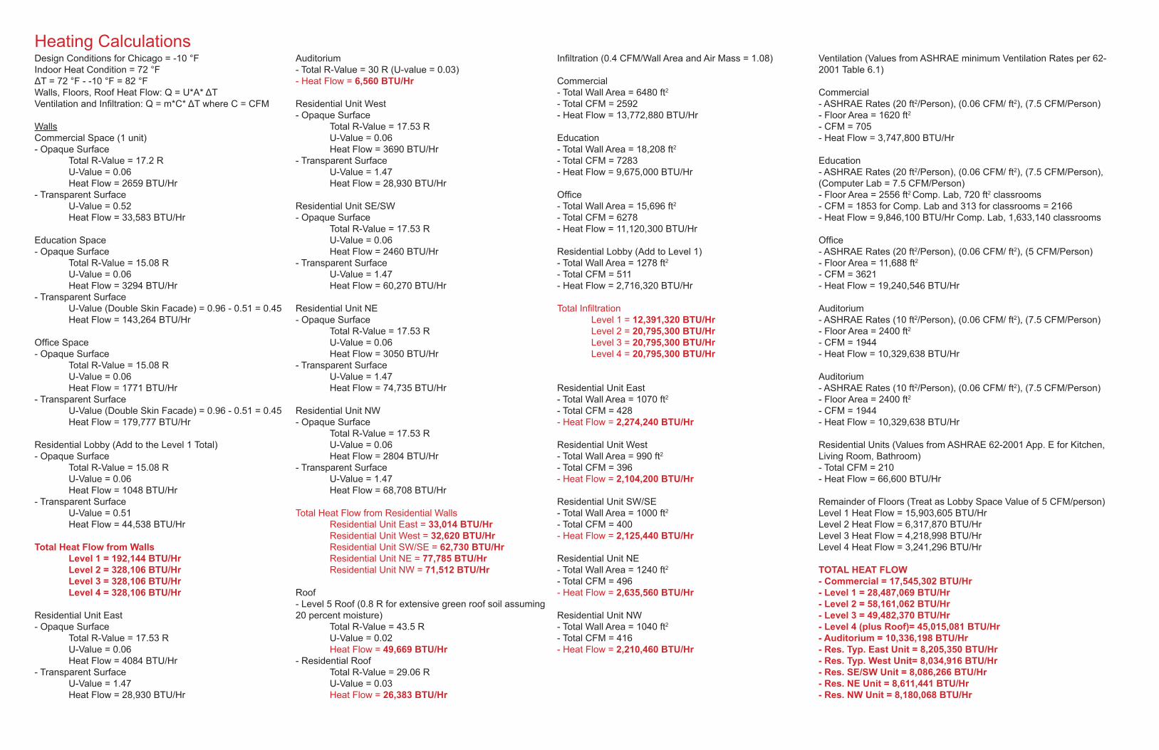
Heating CalculationsDesign Conditions for Chicago = -10 °FIndoor Heat Condition = 72 °FΔT = 72 °F - -10 °F = 82 °FWalls, Floors, Roof Heat Flow: Q = U*A* ΔTVentilation and Infi ltration: Q = m*C* ΔT where C = CFM
WallsCommercial Space (1 unit)- Opaque Surface Total R-Value = 17.2 R U-Value = 0.06 Heat Flow = 2659 BTU/Hr- Transparent Surface U-Value = 0.52 Heat Flow = 33,583 BTU/Hr
Education Space- Opaque Surface Total R-Value = 15.08 R U-Value = 0.06 Heat Flow = 3294 BTU/Hr- Transparent Surface U-Value (Double Skin Facade) = 0.96 - 0.51 = 0.45 Heat Flow = 143,264 BTU/Hr
Offi ce Space- Opaque Surface Total R-Value = 15.08 R U-Value = 0.06 Heat Flow = 1771 BTU/Hr- Transparent Surface U-Value (Double Skin Facade) = 0.96 - 0.51 = 0.45 Heat Flow = 179,777 BTU/Hr
Residential Lobby (Add to the Level 1 Total)- Opaque Surface Total R-Value = 15.08 R U-Value = 0.06 Heat Flow = 1048 BTU/Hr- Transparent Surface U-Value = 0.51 Heat Flow = 44,538 BTU/Hr
Total Heat Flow from Walls Level 1 = 192,144 BTU/Hr Level 2 = 328,106 BTU/Hr Level 3 = 328,106 BTU/Hr Level 4 = 328,106 BTU/Hr
Residential Unit East- Opaque Surface Total R-Value = 17.53 R U-Value = 0.06 Heat Flow = 4084 BTU/Hr- Transparent Surface U-Value = 1.47 Heat Flow = 28,930 BTU/Hr
Auditorium- Total R-Value = 30 R (U-value = 0.03)- Heat Flow = 6,560 BTU/Hr
Residential Unit West- Opaque Surface Total R-Value = 17.53 R U-Value = 0.06 Heat Flow = 3690 BTU/Hr- Transparent Surface U-Value = 1.47 Heat Flow = 28,930 BTU/Hr
Residential Unit SE/SW- Opaque Surface Total R-Value = 17.53 R U-Value = 0.06 Heat Flow = 2460 BTU/Hr- Transparent Surface U-Value = 1.47 Heat Flow = 60,270 BTU/Hr
Residential Unit NE- Opaque Surface Total R-Value = 17.53 R U-Value = 0.06 Heat Flow = 3050 BTU/Hr- Transparent Surface U-Value = 1.47 Heat Flow = 74,735 BTU/Hr
Residential Unit NW- Opaque Surface Total R-Value = 17.53 R U-Value = 0.06 Heat Flow = 2804 BTU/Hr- Transparent Surface U-Value = 1.47 Heat Flow = 68,708 BTU/Hr
Total Heat Flow from Residential Walls Residential Unit East = 33,014 BTU/Hr Residential Unit West = 32,620 BTU/Hr Residential Unit SW/SE = 62,730 BTU/Hr Residential Unit NE = 77,785 BTU/Hr Residential Unit NW = 71,512 BTU/Hr
Roof- Level 5 Roof (0.8 R for extensive green roof soil assuming 20 percent moisture) Total R-Value = 43.5 R U-Value = 0.02 Heat Flow = 49,669 BTU/Hr- Residential Roof Total R-Value = 29.06 R U-Value = 0.03 Heat Flow = 26,383 BTU/Hr
Infi ltration (0.4 CFM/Wall Area and Air Mass = 1.08)
Commercial- Total Wall Area = 6480 ft2
- Total CFM = 2592- Heat Flow = 13,772,880 BTU/Hr
Education- Total Wall Area = 18,208 ft2
- Total CFM = 7283- Heat Flow = 9,675,000 BTU/Hr
Offi ce- Total Wall Area = 15,696 ft2
- Total CFM = 6278- Heat Flow = 11,120,300 BTU/Hr
Residential Lobby (Add to Level 1)- Total Wall Area = 1278 ft2
- Total CFM = 511- Heat Flow = 2,716,320 BTU/Hr
Total Infi ltration Level 1 = 12,391,320 BTU/Hr Level 2 = 20,795,300 BTU/Hr Level 3 = 20,795,300 BTU/Hr Level 4 = 20,795,300 BTU/Hr
Residential Unit East - Total Wall Area = 1070 ft2
- Total CFM = 428- Heat Flow = 2,274,240 BTU/Hr
Residential Unit West - Total Wall Area = 990 ft2
- Total CFM = 396- Heat Flow = 2,104,200 BTU/Hr
Residential Unit SW/SE- Total Wall Area = 1000 ft2
- Total CFM = 400- Heat Flow = 2,125,440 BTU/Hr
Residential Unit NE- Total Wall Area = 1240 ft2
- Total CFM = 496- Heat Flow = 2,635,560 BTU/Hr
Residential Unit NW- Total Wall Area = 1040 ft2
- Total CFM = 416- Heat Flow = 2,210,460 BTU/Hr
Ventilation (Values from ASHRAE minimum Ventilation Rates per 62-2001 Table 6.1)
Commercial- ASHRAE Rates (20 ft2/Person), (0.06 CFM/ ft2), (7.5 CFM/Person)- Floor Area = 1620 ft2
- CFM = 705- Heat Flow = 3,747,800 BTU/Hr
Education- ASHRAE Rates (20 ft2/Person), (0.06 CFM/ ft2), (7.5 CFM/Person), (Computer Lab = 7.5 CFM/Person)- Floor Area = 2556 ft2 Comp. Lab, 720 ft2 classrooms- CFM = 1853 for Comp. Lab and 313 for classrooms = 2166- Heat Flow = 9,846,100 BTU/Hr Comp. Lab, 1,633,140 classrooms
Offi ce- ASHRAE Rates (20 ft2/Person), (0.06 CFM/ ft2), (5 CFM/Person)- Floor Area = 11,688 ft2
- CFM = 3621- Heat Flow = 19,240,546 BTU/Hr
Auditorium- ASHRAE Rates (10 ft2/Person), (0.06 CFM/ ft2), (7.5 CFM/Person)- Floor Area = 2400 ft2
- CFM = 1944- Heat Flow = 10,329,638 BTU/Hr
Auditorium- ASHRAE Rates (10 ft2/Person), (0.06 CFM/ ft2), (7.5 CFM/Person)- Floor Area = 2400 ft2
- CFM = 1944- Heat Flow = 10,329,638 BTU/Hr
Residential Units (Values from ASHRAE 62-2001 App. E for Kitchen, Living Room, Bathroom)- Total CFM = 210- Heat Flow = 66,600 BTU/Hr
Remainder of Floors (Treat as Lobby Space Value of 5 CFM/person)Level 1 Heat Flow = 15,903,605 BTU/HrLevel 2 Heat Flow = 6,317,870 BTU/HrLevel 3 Heat Flow = 4,218,998 BTU/HrLevel 4 Heat Flow = 3,241,296 BTU/Hr
TOTAL HEAT FLOW- Commercial = 17,545,302 BTU/Hr - Level 1 = 28,487,069 BTU/Hr- Level 2 = 58,161,062 BTU/Hr- Level 3 = 49,482,370 BTU/Hr- Level 4 (plus Roof)= 45,015,081 BTU/Hr- Auditorium = 10,336,198 BTU/Hr- Res. Typ. East Unit = 8,205,350 BTU/Hr- Res. Typ. West Unit= 8,034,916 BTU/Hr- Res. SE/SW Unit = 8,086,266 BTU/Hr- Res. NE Unit = 8,611,441 BTU/Hr- Res. NW Unit = 8,180,068 BTU/Hr

Electrical Calculations Plumbing Fixture CalculationsCooling CalculationsDesign Conditions for Chicago = 95 °FIndoor Heat Condition = 68 °FΔT = 95 °F - 68 °F = 27 °F
Indoor Gains Values (From Table F.3)Indoor Heat Gain = Heat Gain Values * Floor Area- Commercial = 13.9 (People + Equipment), 0.6 (Electrical Light)- Education = 3.4 (People + Equipment), 0.6 (Electrical Light)- Apartments = 2 (People + Equipment), 0.7 (Electrical Light)
Outdoor Gains (T = Transparent, O = Opaque) Window Gains = [TOTAL (T) / TOTAL Floor Area] x 21 Opaque Gains = [TOTAL (O) / TOTAL Floor Area] x 25 Infi ltration = [TOTAL(T + O) / TOTAL Floor Area] x 1.9 Ventilation = [TOTAL CFM / TOTAL Floor Area] x 27
TOTAL Indoor Heat Gain (TOTAL Indoor + TOTAL Outdoor)- Commercial = 23,518 BTU/Hr - Level 1 = 26, 037 BTU/Hr- Level 2 = 75,409 BTU/Hr- Level 3 = 65,463 BTU/Hr- Level 4 = 68,195 BTU/Hr- Res. Typ. East Unit = 2200 BTU/Hr- Res. Typ. West Unit= 1964 BTU/Hr- Res. SE/SW Unit = 1736 BTU/Hr- Res. NE Unit = 2590 BTU/Hr- Res. NW Unit = 2229 BTU/Hr
Electrical Power = (Watts/Area) * AreaVoltage = 277 VTotal Current = Power/Voltage
Commercial (1.7 W/ ft2 Lighting, 1.7 W/ ft2 Equip., 8 W/ ft2 HVAC) Total Power = 18,144 W Total Current = 66 A
Education (1.3 W/ ft2 Lighting, 1.7 W/ ft2 Equip., 8 W/ ft2 HVAC)- Level 1 Total Power = 73,915 W Total Current = 267 A- Level 2 Total Power = 84,715 W Total Current = 306 A- Level 3 Total Power = 56,419 W Total Current = 204 A- Level 4 Total Power = 64,195 W Total Current = 232 A
Machine Room-less Elevator Power = ([Force x distance] / time) Elevator mass = 1400 lb, acceleration = 32.2 ft/s2
D1 (Institution) = 62 ft, D2 (Residential) = 158 ft T1 (Institution) = *[200 ft/s] / 62 ft = 3 s = 0.75 s per fl oor T2 (Residential) = *[500 ft/s] / 158 ft = 3 s = 0.38 s per fl oor Elevator 1 Power = 15,027 W (3757 W per fl oor) Elevator 2 Power = 15,027 W (9392 W per fl oor) Elevator 1 Current = 54 A (13.5 A per fl oor) Elevator 2 Current = 54 (34 A per fl oor)
Residential (3 W/ ft2 Lighting, 1.5 W/ ft2 Equip., 5 W/ ft2 HVAC)- Typical East Unit Total Power = 7667 W Total Current = 28 A- Typical West Unit Total Power = 6755 W Total Current = 25 A- SE/SW Unit Total Power = 5938 W Total Current = 22 A- NE Unit Total Power = 8978 W Total Current = 32 A- NW Unit Total Power = 7695 W Total Current = 28 A
Auditorium Total Power = 20,160 W Total Current = 73 A
* = standard speed of elevator per fl oor number
Per Section 890.810 & Section 890 Appendix A Table BTotal People = Total Floor Area / Floor Area/PersonAssume 50 percent men and 50 women of Total People
Commercial (per unit) Value from Code = 100 ft2/Person Total People = 16 (8 men and 8 women)
Offi ce (per Floor from Level 2 - Level 4) Value from Code = 200 ft2/Person Total People = 58 (29 men and 29 women)
Education - Level 1 Value from Code = 50 ft2/Person Total People = 136 (68 men and 68 women)- Level 2 Value from Code = 50 ft2/Person Total People = 156 (78 men and 78 women)- Level 3 Value from Code = 50 ft2/Person Total People = 104 (52 men and 52 women)- Level 4 Value from Code = 50 ft2/Person Total People = 118 (59 men and 59 women)
Auditorium (Add to Level 1) Value from Code = 50 ft2/Person Total People = 48 (24 men and 24 women)
* Residential = 1 WC, 1 LAV, 1 Sink, 1 Shower per unit
TOTAL Plumbing Fixtures per Floor/Program- Commercial = 1 WC, 1 LAV, 1 Sink- Level 1 = 8 WC, 2 UR, 8 LAV, 1 SS, 2 DF- Level 2 = 7 WC, 3 UR, 8 LAV, 1 SS, 2 DF- Level 3 = 7 WC, 3 UR, 8 LAV, 1 SS, 2 DF- Level 4 = 7 WC, 3 UR, 8 LAV, 1 SS, 2 DF- Residential (8 levels x 12 units/level = 96 units total= 1 WC, 1 LAV, 1 Sink, 1 Shower per unit
TOTAL Count = 125 WC, 11 UR, 128 LAV, 100 SS, 8 DF

Systems Path Throughout the Building
Legend
Air Handling Unit
Air Supply
Air Return
Water Supply
Stormwater Runoff
Fire System Control Room
Utility Line from Transformer
Telecommunications Room
Power Panel
Conduit Path
Chilled Water
Hot Water
Fire Sprinklers
B1
L1
L2 (L3 and L4 same with additional classrooms)
NS

Process Work and Final Physical Model


P-Chord Market
Initial Building Area: 120,000 sq. ft. (60 ft x 500 ft x 4 levels)
Proposed Design Square Footage: 50,175 sq. ft including indoor garden (23,775 excluding roof top)Spacing between the bays: 15 bays
Program Area Summary: Indoor farming facility with an indoor and outdoor market place. The spine element is functioning as an indoor agricultural production and fi sh domestication.
Site & Context Description: The region around downtown Detroit consists of numerous farm lands as agriculture contributes $91.4 billion dollars to the state economy according to most recent data from USDA.
Budget & Constraints: Exterior shell is the set limit.
Activity Space Description: Restaurants (4500 sq. ft. which 40% is kitchen, storage, cooking, preparation; 60% is dining room)on each end of the building; bathrooms (120 sq. ft each) are located just underneath the restaurant; loading dock (3600 sq. ft) con-sists of mechanical, electrical, and market storage space. The indoor farm representing the spine (~20 ft x 400 ft = ~8475 sq. ft.) is held above the market where it is accessible to the pub-lic during the seasonal market operating hours. The north end contains three 7,500 cubic ft aquaponic tanks (6.5” thick acryllic glass) for Tilapia on the fi rst level while the three 3,750 cubic ft (3” thick acryllic glass) on the third level are for the rainbow trout and chinook salmon. Roof top is a green roof which also serves as a natural water fi ltering mechanism streaming towards the fi sh tank. The market area is 22,800 sq.ft of space. The 5th level (offi ce space), 4th level (authorized garden space), and 2nd level (gallery space) are all 3600 sq. ft. each. The extensive green roof system serves as a fi lter for the aquaponic tanks as water pumps out from tanks through green roof. The roof also has a retractable glass cover for the winter seasons in order to shield roof top from freezing temperatures while still operating as a fi lter.
Client and User Description: The users of the space will be farmers, USDA researchers, zoologists, and of course the gener-al public during the seasonal market operation.
Project Goals and Priorities: Keeping the existing exterior struc-ture to retain the Packard Identity while re-designing the interior to successfully establish a seasonal market place and full-time farm.
Estimated Air Quantity for space: 75 degrees nearly all day; approximately 9,030,042.518 cfm of air needed for space
Building Information

The Packard Automotive Plant is a former automobile-manufac-turing factory in Detroit, Michigan where luxury Packard cars were made by the Packard Motor Car Company and later by the Stude-baker-Packard Corporation.
The 3,500,000-square-foot, plant was designed by Albert Kahn Associates using Trussed Concrete Steel Company products. It is located on 40 acres of land on East Grand Boulevard on the city’s east side. It included the fi rst use of reinforced concrete in the Unit-ed States for industrial construction in the automobile industry.
Packard Plant’s building number 10 during expansion circa 1911The Packard plant was opened in 1903 and at the time was consid-ered the most modern automobile manufacturing facility in the world with skilled craftsmen involved in over eighty trades. The factory complex closed in 1958, though other businesses operated on the premises or used it for storage until the late 1990s.
A number of the outer buildings were in use by businesses up through the early 2000s. In 2010, the last remaining tenant, Chemi-cal Processing, announced its intention to vacate the premises after 52 years. As of March 2012, however, Chemical Processing remains on the premises.
Since its abandonment, the plant has been a haven for graffi ti van-dals, urban explorers, paintballers and auto scrappers, and much of the wiring and other building material has been scavenged. In one incident, vandals pushed a dump truck from the fourth fl oor. Karen Nagher, the executive director of the nonprofi t organization Preservation Wayne, stated that she was irked to see people come from “all over the world” to poke around Detroit. “Piece by piece, they’re disassembling those buildings, making it harder and harder to restore them”.
Despite many years of neglect and abuse, the reinforced concrete structures remain mostly intact and structurally sound. Portions of the upper fl oors of several small sections in various buildings have collapsed or been partly demolished and lay in ruins in the wake of several aborted attempts at demolition over the years.
The City of Detroit has pledged legal action to have the property demolished or secured. Dominic Cristini, whose claim of ownership is disputed, was said to be conducting construction surveys in ad-vance of full-scale demolition as of early 2012.On February 5, 2013 it was reported that aluminum letter placards spelling the Nazi Slogan “Arbeit macht frei” (work makes free) were placed in the windows of the E. Grand Boulevard bridge. Communi-ty volunteers promptly removed the letters.In April 2013, it was announced that AMC’s Low Winter Sun would be fi lming around the location.
Sources: - http://en.wikipedia.org/wiki/Packard_Automotive_Plant- Olsen 2002, p. 38 “In 1905 Kahn and Julius designed the Packard Plant number 10 using steel-reinforced concrete, the fi rst such application for an industrial plant”.- Smith 1994, p. 59 “Together they built ten works buildings for Packard, Plant No. 10 (1905) be-ing the fi rst reinforced concrete structure in the automobile industry, notable for its lengths of open space between columns and the good lighting from near-fl oor-to-ceiling windows”.- Darley 2003, p. 82 “The example of fl exibility that he chose to illustrate was Albert Kahn’s build-ing of 1905 for Packard in Detroit, building No. 10, the fi rst to use the Kahn reinforced concrete system successfully, which has been effortlessly extended by an additional two stories in 1911”.
Site Information
N

New Buildings
Old Buildings
Demolished BuildingsMarket/RestaurantCommunity CenterResidencesHostel
Tram Station/Information CenterInspiration CenterCo-Op Work/Display SpaceMusic Forum
Spine
N

Building plans and geometry
P-Chord MarketThe P-Chord market in Detroit is a rehabilitation of an old car factory. The existing structure is kept and the new building is inserted in the old skeleton. The grid of 15x15’ is maintained, and the structural frame of columns and slabs, 2’ by 2’ is also kept.The market consists of an immense open space, with several
accompanying programs on both ends, and a connection between them.The accompanying programs are a restaurant, but also an exhibition
The roof of the market building is treated as a green roof, with cultures on it. A small section of the end section is also a garden, but a closed, more private one this time.
The building is well oriented, with a prominent north-south direction. The south facing wall is more open and allows for sun to illuminate the space, while the northern wall is much less permeable, all the while
480’
60’
Building Plans and Geometry
P-Chord Market
Level 1Market
Bathrooms
Surveillance Offi ce
Mechanical/Electrical
Loading Dock
Elevator
Level 2Workshop Showroom
Elevator
Level 3P-Chord Garden Restaurant
Staff Access Strip
Elevator
Level 4Indoor Farm (Spine)
Staff Access Area
Elevator
Level 5Fridge Space
Work Space
Extensive Green Roof Filter
Elevator
NSN
EW
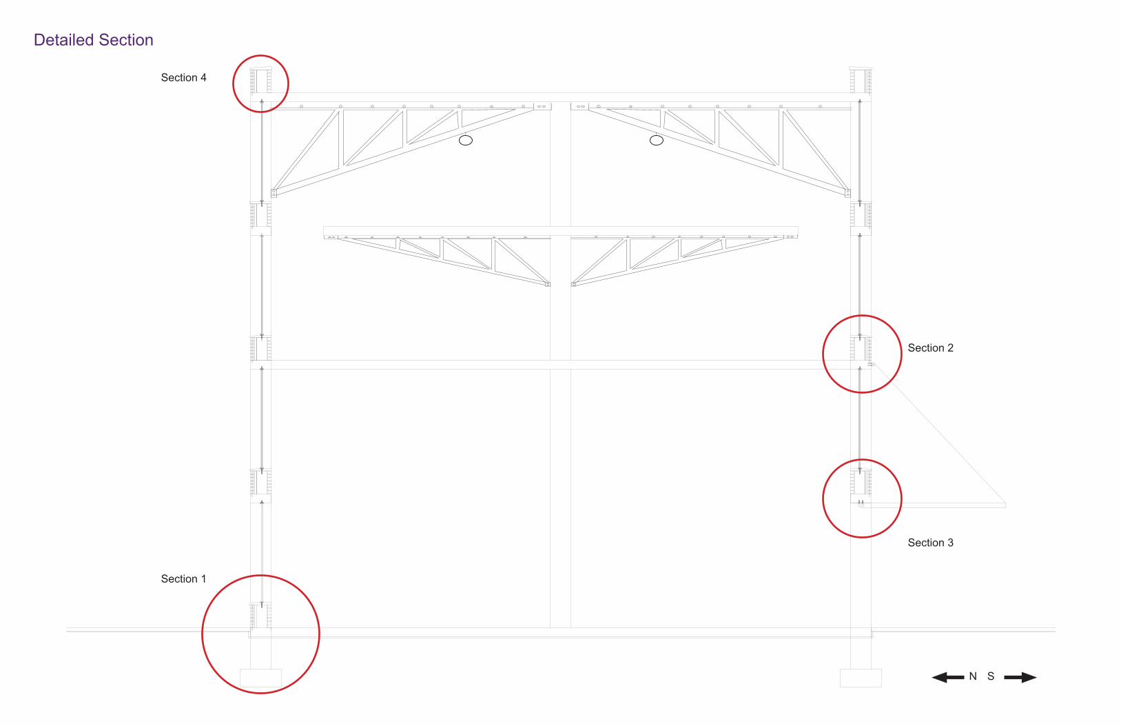
Detailed Section
Section 1
Section 2
Section 3
Section 4
SN

Detailed Section (Continued)
Section 1 - Building Base Anchor
Section 2 - Garage Door Pulley Section 3 - Garage Door Anchor Section 4 - Roof Parapet
Triple Pane Glass
Alumninum Mullion with Thermal Break
Vapor Barrier
2” Polystyrene Board Insulation
4” x 8” Low Density Brick w/ 3/8” Concave Finish Mortar, Rein-forced by #4 Rebar
1-1/2” Air Space
Existing Concrete Wall
Stone Finish Sill Cover
Anchor Bolt
Existing Concrete Footing
Garage Door Garage Pin Connection
Garage Pulley
Order of Materials of Opaque Wall from Outside to Inside
4” x 8” Low Density Brick w/ 3/8” Concave Finish Mortar, Rein-forced by #4 Rebar
Existing Concrete Column
OutsideInside Inside
Outside
Inside
Outside
For roof top details, see next page (Extensive Green Roof Filtration System)
Soil Soil

Extensive Green Roof Filtration System


General Growing Tips
All of these plants require well-draining soil, which means you will either need to use a pot with holes in the bottom or pile up some stones in the bottom of your pot before adding soil (so that the water can drain through the stones). If you choose to use a pot with holes in the bottom, be sure to put a shallow drainage container under the pot so the water doesn’t drain onto your fl oor, shelf, or windowsill.For each of these plants, feel free to purchase potting mix at a garden center or make your own (You can also choose whether or not you want to stick with organic soils). Each plant grows best in a slightly different soil environment, but this general potting mix recipe will help get you started. Many of these plants grow best in areas that receive lots of sunlight and remain fairly warm throughout the day. Sunny WINDOWS are extremely helpful for growing plants indoors. However, if you don’t have sunny windows (or if the area is a low temperature), grow lights will be your new best friend — they help maintain optimal light and tem-perature conditions for plants regardless of outside weather or indoor conditions.
http://greatist.com/health/best-plants-to-grow-indoors
Avocado
Carrot
Garlic Green
Lemon
Mandarin Orange
Microgreen
Mushroom
Salad Green
Scallion
Tomato
Basil Leaves
Chives
Cilantro
Ginger
Mint Leaves
Rosemary
Interior DH exterior fan location
Carbon Filter FANS: Pull Air
Vent
Exhaust fan: controls humidity
CO2 Controlled Sealed EnvironmentCool air goes through the hood w/ out contacting the air in the space, keeping CO2 locked in for maximum yields. It is necessary to have a dehumidifi er or an exhaust fan.
Proper air fl ow for a space brings cool air and exhausts hot air out. The carbon fi lter eliminates odor before leaving the growing space.
Indoor Garden DiagramsHow an Aquaponic Works
Fish Tank
Grow Bed
WaterWater pumped through the grow bed (roof top) and fi ltered by plants and then returned to the fi sh tank.
PlantsPlants absorb the nitrates as nutrients. Plants are usually suspended on fl oating raft platforms. In the case of the market place, they are on rooted in the rooftop on top of gravel.
BacteriaNaturally occurring bacteria convert ammo-nia into nitrites and then eventually into nitrates.
H
O
O
OxygenFish breathe in oxygen and breathe out carbon dioxide. Plants absorbed the harmful ammonia byproducts such as nitrates leaving root-cleansed water to return to the fi sh tank.
FishFish are fed food and produce ammonia-rich waste. When the fi sh grow to market size, they can be sold and replaced with new fi sh reared from the eggs.


Climate analysis
WindsOne of the particularities of the site is its northwestern winds in the winter and southeastern ones in the summer. Coincidently, the building is aligned on these axes, and the further development of cross ventilation hugely improved with the favorable winds on the main facades in both winter (protected) and summer (more open).
Design ConditionsThe design conditions for this project in Detroit, Michigan are as follow (Table B.1);Winter Dry-Bulb : 8.4 °FSummer Dry-Bulb : 85.8 °F
Sun position is as follows :
Winter solstice : 25°
Climate Analysis
Winds
Design Conditions

Passive heating strategies
Thermal MassThe building being open on the south end, we used this to our advantage by having the connecting bridge supported by massive supports acting as thermal masses, instead of the pre existing columns. In the winter, the sun’s angle is 25°, allowing it to penetrate the building and warming the material of the supports, that can then be released later during the evening to keep the place warm.During the summer, on the other hand, the
thermal masses are kept under shadow and therefore do not create any unnecessary heat during the already warm days.
Green RoofOn the roof there is a green roof that also acts as a thermal mass during the winter. This is possible because in the winter, there is a greenhouse placed on top of the building, allowing the heat to get trapped, and redirected towards the rest of the building. The massive roof slab together with the soil act as a very good thermal mass.During the summer this doesn’t happen; the greenhouse isn’t present anymore, and the heat collected by the green roof is released in the air without getting trapped and without making its way into the rest of the building.
Passive Heating Strategies
Thermal Mass
Green Roof

Passive cooling strategies
Cross VentilationThe market building being very long and
cross ventilation. The building is also very well oriented with the winds, receiving southeastern winds in the summer and northwestern winds in the winter. By opening it up on the south end and western end, air circulates very well, and maintains the whole area well ventilated.
Evaporative Cooling
strategy has been developed. With a combination of cross ventilation, and due to the position of the pond and vegetation, passive evaporative cooling is possible by bringing in moist air and therefore
building.The micro climate generated by the elements permits a natural ventilation of the space. This could be reinforced with a mechanical fan, but it would lose its passive
Passive Cooling Strategies
Cross Ventilation
Evaporative Cooling

Process Work and Final Physical Model


Pompidou Centre Structural Analysis ModelThe primary structural system used for the Pompidou is the cross-braced structural system. The secondary structural system is the moment frame where the trusses support the slabs. The reason it uses the cross-braced method is to help stabilize the series of moment frames of the long span trusses that act as beams span-ning approximately 157 feet (48 meters) across. The depth of the beam is 7 feet, which brings the span-to-depth ratio of the truss beams to 22.6 feet-to-1 foot. The maximum span a beam may span prior to the start of bend-ing deformation is 20 feet per 1 foot of depth. Furthermore, the fact that the beams are K-series trusses means that there is less surface area of the beam, making the structural system even more fi nancially economical.
Although the span-to-depth ratio of the trusses are slightly above the theoretical maximum of 20:1, the reason why these beams are able to get by this is from the support of the gerberettes. These elements are pinned to the inner and outer columns while also being pinned to the trusses. As a result, when the slab’s mass presses down on the trusses, the gerberettes respond to these forces by transferring the load forces to the inner column in compression while simultaneously transferring the loads to the outer columns in tension. This balances the tension and compression forces, bringing the overall structure to a pure equilibrium.
The typical and simpler yet least fi nancially economical way to construct the Pompidou would be to design the structure with much thicker columns without gerberettes. This means that the overall structure would be a moment frame with shears walls serving as the secondary system. The columns of the Pompidou are approxi-mately 138 feet (42 meters) tall. The maximum height a fi xed column may go prior to buckling is 50 feet tall per 1 foot depth. Theoretically, if the column goes 138 feet tall, the minimum depth the column may go is 2.76 feet assuming they are not hollow steel sections. For circular hollow steel sections, the columns may reach higher altitude with less depth at 70 feet tall per 1 foot depth. For the case of the Pompidou, the minimum depth the column would need theoretically is 1.97 feet depth rather than 2.75 feet of depth. This structure uses circular hollow steel columns to maximize the height while using less material and providing maximum resistance to buckling, resulting in lower eccentricity and lower bending moment.
The structure resists lateral loads is from the series of cross-braces used on the longer sides of the structure with each brace set pinned to the outer columns. This helps provide higher stability to the thinner outer columns with less material. There are three total sets of cross-braces per shorter side and six total per fl oor with the exception of the fi rst fl oor. The cross-braces on the shorter sides of the Pompidou are placed at the ends and middle of the trusses from levels 2-6. On the fi rst level, the cross-braces are placed in between the inner and outer columns. The middle cross-braces are pinned to the truss chords only while the end braces are pinned to the truss chords and the gerberettes. The reason why there are less cross braces on the shorter ends in comparison to the longer ends is due to the shorter side being nearly 3 times shorter. This means less bracing is required to stabilize the overall structure due to proportional ratio. As a result, because the tension forces are also resisting the lateral loads, there is no need for a load-bearing wall to be constructed.
The cross-braces on the shorter sides are also used to resist torsion because they contribute additional tension forces to hold the columns from moving in a perpendicular direction from the moment connections. Torsion occurs when two perpendicular forces move in perpendicular directions from each other on the structure. In relation to the structure, the use of all structural elements fabricated into completely closed circular hollow steel improves the resistance to torsion by allowing the stress to travel freely in a radial direction. The easier the path of movement for stress in a geometry, the higher the resistance.
Although the most powerful tool in structural design is geometry, material is also a major contributor to the structural stability of the Pompidou. Steel is a unique material that possesses strong compressive and tensile properties. Therefore, it is very strong in resisting all four types of forces. Its modulus of elasticity is 29,000,000 pounds per inch squared. Due to its strength, there is no need to add more material than necessary and waste additional money, energy and material.
In conclusion, what makes this structure successful is the way the system works. It works like a domino ef-fect where forces are transferred from one element to another very freely to the foundation, resulting in higher resistance to all types of forces. It did not need to have a redundant amount of material. Rather, most of the structural is based off its material geometry, connection locations, and the elements being sized to its appropri-ate proportion.
Summary

Stress Gradient (East Side)
Tensile Forces = RedCompressive Forces = Blue

Stress Gradient (North Side)
Tensile Forces = RedCompressive Forces = Blue
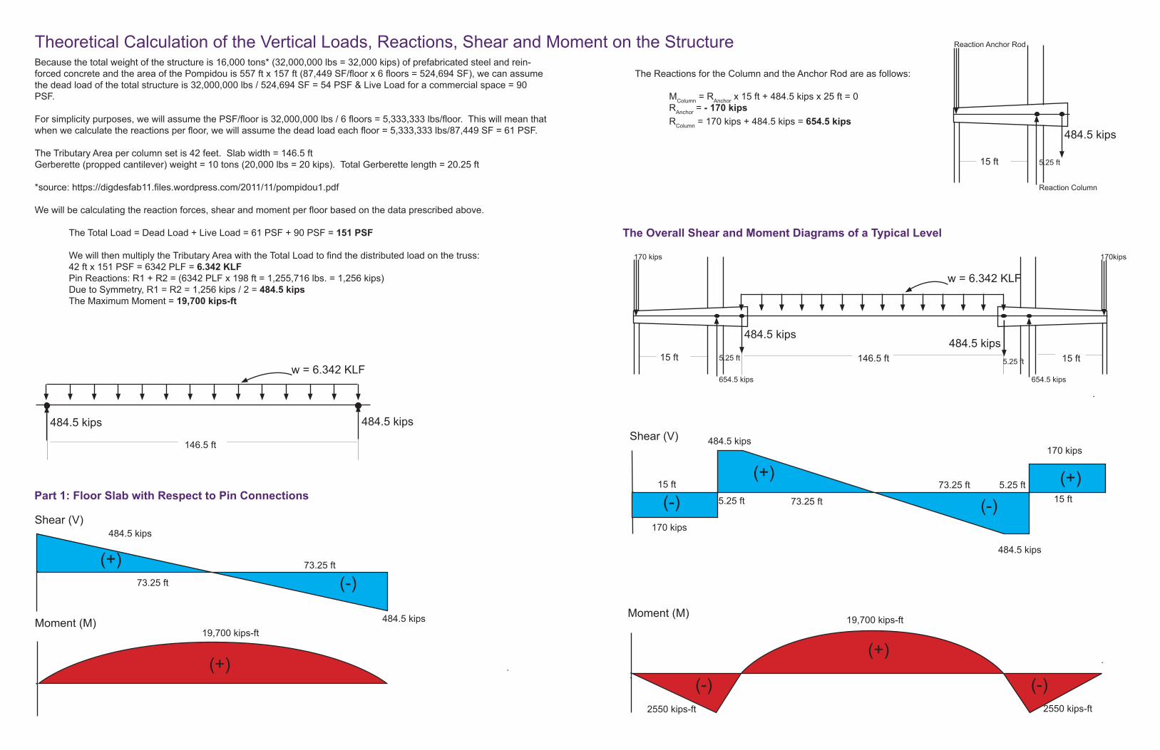
Because the total weight of the structure is 16,000 tons* (32,000,000 lbs = 32,000 kips) of prefabricated steel and rein-forced concrete and the area of the Pompidou is 557 ft x 157 ft (87,449 SF/fl oor x 6 fl oors = 524,694 SF), we can assume the dead load of the total structure is 32,000,000 lbs / 524,694 SF = 54 PSF & Live Load for a commercial space = 90 PSF.
For simplicity purposes, we will assume the PSF/fl oor is 32,000,000 lbs / 6 fl oors = 5,333,333 lbs/fl oor. This will mean that when we calculate the reactions per fl oor, we will assume the dead load each fl oor = 5,333,333 lbs/87,449 SF = 61 PSF.
The Tributary Area per column set is 42 feet. Slab width = 146.5 ftGerberette (propped cantilever) weight = 10 tons (20,000 lbs = 20 kips). Total Gerberette length = 20.25 ft
*source: https://digdesfab11.fi les.wordpress.com/2011/11/pompidou1.pdf
We will be calculating the reaction forces, shear and moment per fl oor based on the data prescribed above.
The Total Load = Dead Load + Live Load = 61 PSF + 90 PSF = 151 PSF
We will then multiply the Tributary Area with the Total Load to fi nd the distributed load on the truss: 42 ft x 151 PSF = 6342 PLF = 6.342 KLF Pin Reactions: R1 + R2 = (6342 PLF x 198 ft = 1,255,716 lbs. = 1,256 kips) Due to Symmetry, R1 = R2 = 1,256 kips / 2 = 484.5 kips The Maximum Moment = 19,700 kips-ft
w = 6.342 KLF
146.5 ft
484.5 kips
Shear (V)
Moment (M)19,700 kips-ft
73.25 ft
73.25 ft
484.5 kips
Part 1: Floor Slab with Respect to Pin Connections
484.5 kips
(-)(+)
(+)
w = 6.342 KLF
146.5 ft
484.5 kips
5.25 ft5.25 ft 15 ft15 ft
170 kips 170kips
654.5 kips 654.5 kips
Shear (V)
Moment (M) 19,700 kips-ft
73.25 ft
73.25 ft
484.5 kips
484.5 kips
(-)
(+)
(-)
(+)
2550 kips-ft
The Overall Shear and Moment Diagrams of a Typical Level
5.25 ft5.25 ft
170 kips
170 kips
484.5 kips
5.25 ft15 ft
Reaction Anchor Rod
Reaction Column
The Reactions for the Column and the Anchor Rod are as follows:
MColumn = RAnchor x 15 ft + 484.5 kips x 25 ft = 0 RAnchor = - 170 kips RColumn = 170 kips + 484.5 kips = 654.5 kips
15 ft15 ft
(+) (+)(-)(-)
2550 kips-ft
(+)
(-) (-)
484.5 kips
Theoretical Calculation of the Vertical Loads, Reactions, Shear and Moment on the Structure
484.5 kips
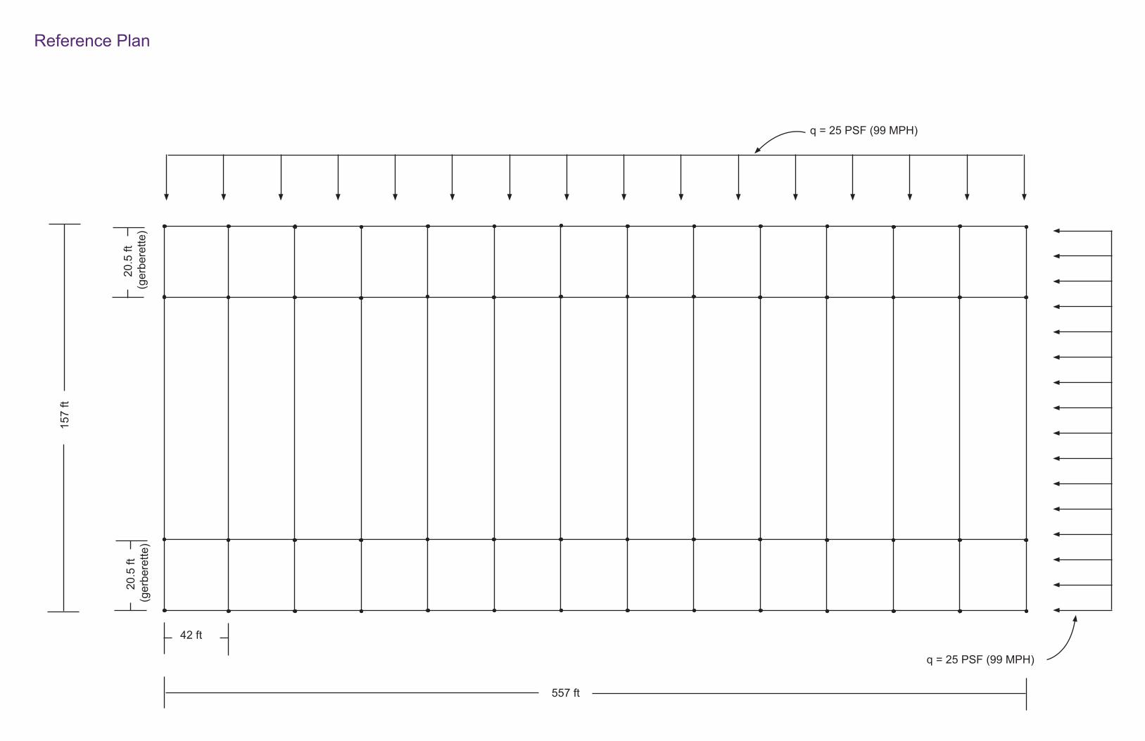
42 ft
157
ft
557 ft
Reference Plan
q = 25 PSF (99 MPH)
q = 25 PSF (99 MPH)
2
0.5
ft(g
erbe
rette
)
20.
5 ft
(ger
bere
tte)
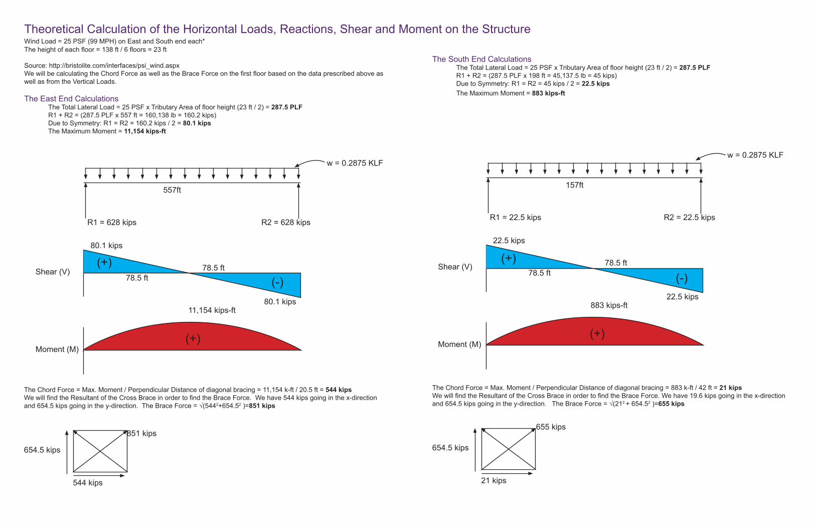
Theoretical Calculation of the Horizontal Loads, Reactions, Shear and Moment on the Structure Wind Load = 25 PSF (99 MPH) on East and South end each*The height of each fl oor = 138 ft / 6 fl oors = 23 ft
Source: http://bristolite.com/interfaces/psi_wind.aspxWe will be calculating the Chord Force as well as the Brace Force on the fi rst fl oor based on the data prescribed above as well as from the Vertical Loads.
The East End CalculationsThe Total Lateral Load = 25 PSF x Tributary Area of fl oor height (23 ft / 2) = 287.5 PLFR1 + R2 = (287.5 PLF x 557 ft = 160,138 lb = 160.2 kips)Due to Symmetry: R1 = R2 = 160.2 kips / 2 = 80.1 kipsThe Maximum Moment = 11,154 kips-ft
w = 0.2875 KLF
R1 = 628 kips R2 = 628 kips
Shear (V)
Moment (M)
80.1 kips
80.1 kips11,154 kips-ft
78.5 ft78.5 ft
20.5 ft
544 kips
654.5 kips
557ft
The Chord Force = Max. Moment / Perpendicular Distance of diagonal bracing = 11,154 k-ft / 20.5 ft = 544 kipsWe will fi nd the Resultant of the Cross Brace in order to fi nd the Brace Force. We have 544 kips going in the x-direction and 654.5 kips going in the y-direction. The Brace Force = √(5442+654.52 )=851 kips
851 kips
(-)(+)
(+)
The South End CalculationsThe Total Lateral Load = 25 PSF x Tributary Area of fl oor height (23 ft / 2) = 287.5 PLFR1 + R2 = (287.5 PLF x 198 ft = 45,137.5 lb = 45 kips)Due to Symmetry: R1 = R2 = 45 kips / 2 = 22.5 kipsThe Maximum Moment = 883 kips-ft
w = 0.2875 KLF
R1 = 22.5 kips R2 = 22.5 kips
Shear (V)
Moment (M)
22.5 kips
22.5 kips883 kips-ft
78.5 ft78.5 ft
20.5 ft
21 kips
654.5 kips
157ft
The Chord Force = Max. Moment / Perpendicular Distance of diagonal bracing = 883 k-ft / 42 ft = 21 kipsWe will fi nd the Resultant of the Cross Brace in order to fi nd the Brace Force. We have 19.6 kips going in the x-direction and 654.5 kips going in the y-direction. The Brace Force = √(212 + 654.52 )=655 kips
655 kips
(-)(+)
(+)

The Physical Model
TransversalBracing
LongitudinalBracing
While very systematic, the model needed to defl ect and each component had to be assembled separately and tested for reactions. The trusses were each assembled by elements to allow for an acceptable defl ection. In total, 84 trusses were built and assembled separately. There were about 1200 separate compression chords, which were tied together with fi shing string to simulate the tension steel cable to allow for visible defl ection.
The trusses were then pin connected to the gerberettes, which in turn were pin-connected to the columns. Temporary bracing and support had to be built before the fi nal string bracing was assembled. Without the tension cables, the gerberettes would thrust upwards under the weight of the trusses. Once the tension cables are in place, the model is still very unstable because it is not braced, neither longitudinally nor transversely. Temporary bracing was put in place in the middle section of the model while everything was attached.
Putting the fi nal bracing together was the crucial part as it strengthened the whole model overall. And while the separate parts were delicate, once everything is braced, the structure felt much more solid.
The process that was tideous was preparing, testing and building different elements. After the success of the fi rst set of trusses, all the elements were prepared in advance. This expedited the construction of the model.
Model Construction

Centre Pompidou

TensionCompression
GerberetteDetail