amendments to the technical specifications (volume 1-c2 ... information.pdf · tender documents lot...
TRANSCRIPT
Madhya Bhotekoshi Jalavidyut Co. Ltd. Maharajgunj, Kathmandu Nepal
Middle Bhotekoshi Hydroelectric Project Tender Documents Lot 1
Addendum No. 1
Lahmeyer International GmbH
in association with TMS, Nepal
May 2013
MADHYA BHOTEKOSHI JALAVIDYUT COMPANY LIMITED
Middle Bhotekoshi Hydroelectric Project (102 MW)
ADDENDUM NO 1
Additional Information (for Section 12 Changes to Volume 3 – Hydromechanical
Specification Page 19 – A.2 Gantry Monorail Crain)
Lot 1: Civil and Hydro-Mechanical Works (EPC Contract)
Contract Identification No.: MBJCL/MBKHEP/068/69/EPC-1
Madhya Bhotekoshi Jalavidyut Co. Ltd. Maharajgunj, Kathmandu Nepal
Middle Bhotekoshi Hydroelectric Project Bidding Documents Lot 1
Volume 3: Hydromechanical Equipment
Lahmeyer International
in association with TMS, Nepal
Page 1
17. MONORAIL GANTRY CRANE
17.1 Description, Requirements and Data
17.1.0 General
The monorail gantry crane, 5.0 m in span, is intended for installation, operation and removal
of the tailrace stoplogs. The lifting capacity is assumed to be 50 kN subject to the weight of
the stoplogs plus friction. The base of the crane portal shall be designed for passing through
tailrace stoplog section having a width of 3.25 m and a clear height of 1.50 m. The monorail
gantry crane shall be mounted at elevation 925.60 m asl. The monorail gantry crane with the
hoist shall be designed for outdoor operation. The hoist shall be pendent control.
The hoist shall be mounted on the trolley. This trolley shall be mounted on an additionally
monorail. The hoist shall be equipped with single rope drums and one hook for pulley blocks
with an incorporated non-turning lifting hook. The necessary mechanically operated lifting
beam for operation of the tailrace stoplog shall be designed and supplied by the crane
manufacturer. The power supply to the crane shall be through slip rings and the conductors
arranged on the upstream (u/s) side of the crane.
The main dimensions and the arrangement of the monorail gantry crane are shown in the
relevant drawings.
17.1.1 Limits of Supply
With the Civil Works
The Contractor shall provide drawings for any block-outs required for second stage concrete
and supply all first stage anchor plates to be embedded in the first stage concrete. The
second stage embedded parts shall be installed and secured by the Contractor and the
subsequent embedment in concrete shall also be performed by the Contractor.
With the low voltage power supply
All required cabling and equipment to the weatherproof main terminal box (included)
mounted on the outside of the powerhouse. The Lot 2 Contactor shall provide 220V DC
supply to the main terminal box.
17.1.2 Design and Operating Conditions
The monorail gantry crane shall be designed in every respect to safely meet all the
requirements of the power plant, project and relevant standards.
Madhya Bhotekoshi Jalavidyut Co. Ltd. Maharajgunj, Kathmandu Nepal
Middle Bhotekoshi Hydroelectric Project Bidding Documents Lot 1
Volume 3: Hydromechanical Equipment
Lahmeyer International
in association with TMS, Nepal
Page 2
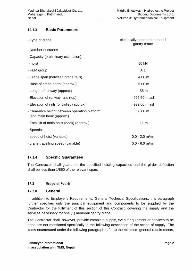
17.1.3 Basic Parameters
- Type of crane electrically operated monorail gantry crane
- Number of cranes
- Capacity (preliminary estimation):
- hoist
- FEM group
1
50 kN
A 1
- Crane span (between crane rails)
- Base of crane portal (approx.)
- Length of runway (approx.)
4.00 m
6.00 m
55 m
- Elevation of runway rails (top)
- Elevation of rails for trolley (approx.)
925.50 m asl
932.00 m asl
- Clearance height between operation platform
and main hook (approx.)
6.00 m
- Total lift of main hoist (hook) (approx.)
- Speeds:
- speed of hoist (variable)
- crane travelling speed (variable)
11 m
0.0 - 2.0 m/min
0.0 - 6.0 m/min
17.1.4 Specific Guarantees
The Contractor shall guarantee the specified hoisting capacities and the girder deflection
shall be less than 1/850 of the relevant span.
17.2 Scope of Work
17.2.0 General
In addition to Employer’s Requirements, General Technical Specifications, this paragraph
further specifies only the principal equipment and components to be supplied by the
Contractor for the fulfilment of this section of this Contract, covering the supply and the
services necessary for one (1) monorail gantry crane.
The Contractor shall, however, provide complete supply, even if equipment or services to be
done are not mentioned specifically in the following description of the scope of supply. The
items enumerated under the following paragraph refer to the minimum general requirements,
Madhya Bhotekoshi Jalavidyut Co. Ltd. Maharajgunj, Kathmandu Nepal
Middle Bhotekoshi Hydroelectric Project Bidding Documents Lot 1
Volume 3: Hydromechanical Equipment
Lahmeyer International
in association with TMS, Nepal
Page 3
but these requirements shall apply to each set to be supplied and any interface equipment
deemed to be necessary between this chapter and other chapters, except where stated
otherwise.
17.2.1 Monorail Gantry Crane Components
The supply shall include the following:
a) one (1) electrically operated monorail gantry crane with hoist;
b) one (1) set of automatic lifting beam; one (1) mechanically operated lifting beam approximately 3 m long, 50 kN lifting capacity for handling, travelling and operation of the mounted stoplog and the stoplog sections;
c) one (1) set of crane rails with all anchorage’s, bumpers, etc.,
d) one (1) set of monorail for suspension of the trolley,
e) one (1) set of electrical feed posts, f) necessary load for load test of the crane (125% of nominal load),
g) all accessories necessary for the gantry crane to be complete and ready for operation when installation is finalised shall be furnished and included in the supply.
17.3 Design, material and workmanship
The design, calculation and manufacture shall be based on FEM standard and relevant
international standards, considering the dimensions, loads and operating conditions as
described and specified in the Particular and General Technical Specification. For calculation
of travelling all friction and dynamic forces and also wind loads shall be considered. The
following wind speeds shall be considered:
In-service design wind speed: 20 m/s equiv. ~ 75 km/h;
Out of service wind speed: 36 m/s equiv. ~130 km/h.
If the wind speed is higher than 75 km/h, the crane shall stop operation, and automatically
electrically operated rail clamps shall fix the crane in its actual position at that time. If the
crane is generally out of operation, the crane shall be positioned and secured in the parking
position. The hoist shall be equipped with load cells for safe operation. The maximum vertical
deflection of the longitudinal or cross beams and the monorail of the monorail gantry crane
caused by nominal load shall not exceed 1/850 of the relevant span. The factor of safety
against overturning under any combination of loadings shall be not less than 2.
Madhya Bhotekoshi Jalavidyut Co. Ltd. Maharajgunj, Kathmandu Nepal
Middle Bhotekoshi Hydroelectric Project Bidding Documents Lot 1
Volume 3: Hydromechanical Equipment
Lahmeyer International
in association with TMS, Nepal
Page 4
17.4 Specific requirements of components
17.4.0 General
The specific requirements indicated hereunder are in addition to and in completion of those
arising from the Contractor’s obligations to supply goods and designs suitable to fulfil the
performance and requirements of the complete supply covered by this section.
17.4.1 Gantry Structure
The gantry structure shall be of welded steel box design, with necessary cross girders and
pairs of legs. Boogies for housing of travelling and driving rollers, wheel break supports, rails,
tongs and stoppers and locking devices to block the gantry in end position shall be provided.
Ventilated compartments for protection of the equipment against weather shall be arranged.
Walkways and ladders shall be installed for access.
17.4.2 Girders
The girders shall be box-type welded from structural steel. The box girder’s inside may be
used for electrical installations. The deflection of the central supporting beam structures
under normal design load shall not exceed 1/850 of the span.
17.4.3 Crane Legs and Sills
The crane legs and sill beams shall be welded structural steel. The crane leg connection to
girders on the upstream side shall be rigid bolt connected and on the downstream side may
be a pivoted pin joint or a semi-rigid bolted joint. Sill beams shall be furnished with skirt
plates to protect the crane drive mechanism, trucks and bumper parts from direct effects of
weather and windborne debris. The manufacturer shall furnish one link at each of the sill
beams for anchoring the crane (against all calculated forces) to the head of the crane rail at
any position on the crane runaway.
17.4.4 Bumpers
Spring or elastometric bumpers shall be provided on each end of the crane sill beams and on
each corner of the trolley. The bumpers shall consist of suitable springs, steel housings and
rams or, alternately, of adequately sized elastometric pads.
17.4.5 Crain Rails
The rails shall be provided over the full length of the Crain travel shall confirms DIN 4132 and
DIN 18800 or equivalent international standards subject to Engineer’s approval with all
holding down bolts, clamps, fishplates, separators, end buffer stops etc., and shall be
gapped at any expansion joints in the concrete. The rail joints are to be cut at 45° to ensure a
smooth load transfer. The rails shall be dismountable and be fixed by rail clamps which
confirm DIN 4132 or equivalent international standards subject to Engineer’s approval.
Madhya Bhotekoshi Jalavidyut Co. Ltd. Maharajgunj, Kathmandu Nepal
Middle Bhotekoshi Hydroelectric Project Bidding Documents Lot 1
Volume 3: Hydromechanical Equipment
Lahmeyer International
in association with TMS, Nepal
Page 5
17.4.6 Mechanically Operated Lifting Beam
The mechanically operated lifting beam shall be mainly consists of a steel frame, lifting lug,
counter weights, guide rollers and balance weight. The steel frame of the lifting beam shall
be a box type steel construction. The hydraulically operated lifting beam shall equip a sensor
for checking if the lifting beam reaches the required position.
17.4.7 Crane Travelling Gear
The separate drive of the crane shall be equipped with a drive motor, closed oil bath
lubricated reduction gear, brake and steel pinion for the travelling roller drive. All the brakes
shall have adequate capacity. The brakes for hoisting when applied shall arrest the motion
and sustain the load up to the test load at any position of the lift. Provision shall be made to
control with safety the lowering of any load up to the test load.
Brakes in other motions shall be capable of bringing the relevant motions of the fully loaded
crane safely to rest in the shortest possible time with the least possible shock, and shall
arrest the motion under all other service conditions.
The various brakes shall be designed to exert a torque equal to 1.5 times of the full load
torque of the motors. The brake torque may be increased if considered necessary by the
manufacturer in order to ensure proper and safe application of the brakes. All electro-
mechanical brake coils shall have continuous ratings.
A minimum of four travelling rollers made of cast steel shall be provided with grease-
lubricated anti-friction bearings.
17.4.8 Hoist
The hoist shall be mounted on the hoist trolley and shall consist of rope drums for pulley
blocks with incorporated a non-turning lifting hook for operation with the hydraulic lifting
beam. The hoist shall be equipped with twist-free ropes.
All deflection and lifting elements which will be operated in the water, i.e. deflection sheaves,
lifting hooks, etc., shall be designed adequately for continuous and reliable operation under
all applicable conditions. The hoist consists of rope drum of welded steel provided with rope
grooves and equipped with bearings, winding motor, closed oil bath lubricated reduction
gear, hoist brake for normal operation actuated by electro-aggregates, additional safety
brake normally with retarded action other than the main brake operation, overload protection,
load cell, galvanised steel wire ropes Warrington Seal type, steel pulley case with rope pulley
and a hook of forged steel provided with a thrust bearing. The manual release of the brakes
shall be possible in case of emergency. The wire rope ends shall be fitted with standard
sleeve clamps.
The trolley housing shall be of steel construction and the covering palates having a thickness
of not less than 3 mm. Inside of the housing shall be isolated with heat resistant material. A
lockable doors and windows shall be provided.
Madhya Bhotekoshi Jalavidyut Co. Ltd. Maharajgunj, Kathmandu Nepal
Middle Bhotekoshi Hydroelectric Project Bidding Documents Lot 1
Volume 3: Hydromechanical Equipment
Lahmeyer International
in association with TMS, Nepal
Page 6
17.4.9 Power Supply
The power to the crane shall be supplied through a conductor together with slip rings. The
slip ring consists with carbon brushes shall be in contact with the conductor during full travel
length of the gantry crane. A main terminal box for power infeed with a separate disconnect
switch for the crane shall be installed on the downstream side on the middle of the
Powerhouse structure. Feeding of this main terminal box will be by Lot 2.
17.4.10 Control and Monitoring
The controls shall be equipped with an emergency mushroom switch for tripping of the main
circuit breaker, with a key switch acting on the main circuit breaker with overload warning
lights for the hoist, and with a slack rope warning light ampere meter, and an indicating
instrument for the depth of the relevant stoplog elements during operation.
The crane shall be equipped with control circuit transformers, motor starters and thermal
overload protection for each motor. Adjustable limit switches of inductive type actuating the
circuit breaker shall be provided for limitation of the lifting and lowering range of the lifting
beam with an additional safety limit switch for the highest hook position.
The hoists of the crane shall also be equipped with a cut-off switch for loads exceeding the
rated capacity. The main and auxiliary hoists shall be equipped additionally with a slack rope
switch, in order to prevent further lowering of the load with slack ropes. Controls and
commands for electro-hydraulic locking installation of lifting beams shall be mounted on the
control board as well.
17.4.11 Crane Controls
All operating manoeuvres shall be made from the pendent control. All control devices shall
be weather-proof and dust tight.
The control desk shall also include the following:
A main voltage switch lockable in the open position,
A warning horn and its push button control,
Switches controlling lighting of the operating cabin, the working area and the lifting mechanism.
A control box having all the control functions of the crane shall be mounted on the
downstream sill beam of the crane to facilitate the short time operation of crane from the
level of the railway. This box shall be provided with lock and keys and shall be weather-proof.
17.4.12 Switchboard
The switchboard containing all elements required for the travelling and lifting operations shall
be installed on the downstream sill beam of the travelling monorail gantry crane, near the
cable winding drum. The switchboard shall be watertight and shall, as a general rule, include

Madhya Bhotekoshi Jalavidyut Co. Ltd. Maharajgunj, Kathmandu Nepal
Middle Bhotekoshi Hydroelectric Project Bidding Documents Lot 1
Volume 3: Hydromechanical Equipment
Lahmeyer International
in association with TMS, Nepal
Page 7
all necessary switchgears, relays and instruments for the power distribution, control,
monitoring, signalling and protection of the crane.
17.4.13 Wiring
All wiring on the crane and on its component assemblies shall be completed at the
Contractor’s plant, except that wiring shall not be installed where it would be disturbed by or
for shipment.
However, a sufficient quantity of cable and associated materials of the proper sizes and
types shall be included with the shipment to permit completion of the crane wiring in the field.
Electrical wiring within the equipment shall be neatly arranged, properly supported, and
terminated so that all external connections can be made to terminal blocks inside the
equipment, or in terminal boxes. Control circuits and power circuits shall be completely
separated by use of divided or separate terminal boxes.
Marking strips shall have wire designations as used on the wiring diagram, or as designated
by the Engineer/Employer. No more than 2 wires shall be connected to any one terminal
block screw.
17.4.14 Lighting and Convenience Outlets
Outdoor lighting of the gantry crane shall include minimum:
2 watertight swivelling 400 W high pressure sodium flood lights located in such a position that they can illuminate the rail track of the monorail gantry crane;
4 watertight swivelling 400 W high pressure sodium flood lights in order to illuminate the hoisting operations.
A total of six 230-volt convenience outlets shall be provided; one at each leg and two at the
operator’s station.
17.4.15 Fire Protection
Provision shall be made for two (2) portable dry powder fire extinguishers of approximately 6
kg weight fitted in the following locations:
inside the main hoist housing,
at the main switchboard.
The instructions for use shall be clearly marked on each of these extinguishers.
17.4.16 Corrosion Protection
The corrosion protection shall be as detailed in the Annex 1 - Painting Schedule, General
Technical Specification.
Madhya Bhotekoshi Jalavidyut Co. Ltd. Maharajgunj, Kathmandu Nepal
Middle Bhotekoshi Hydroelectric Project Bidding Documents Lot 1
Volume 3: Hydromechanical Equipment
Lahmeyer International
in association with TMS, Nepal
Page 8
17.5 Shop assembly and Test
The crane shall be completely assembled at the shop respectively divided into suitable sub-
assemblies to allow final inspection and performance of functional tests.
In particular, the following tests shall be carried out under the supervision of the Employer’s
Representative:
Checking of the main dimensions.
Operational test of all drives, including measurement of operating speeds and load switch adjustments.
Function tests of the complete control system, measurement of stator winding insulation resistance on all driving motors, voltage test and insulation test on electrical installations.
The test equipment and instrumentation has to be provided by the Contractor. When test
equipment has passed the tests to the Employer/ Engineer’s satisfaction, the equipment can
be disassembled touch-up painted and packed for shipment.
17.6 Installation
The Contractor is responsible for the total installation of the gantry cranes. He shall furnish all
materials and devices required for supporting and holding parts in position while the concrete
is being placed.
The Contractor shall perform the following for the installation of each gantry crane:
Install all second stage concrete embedded items of the crane rail system.
Install all non-embedded parts.
Prepare a permanent record of elevations, clearances, tolerances and similar measurements established at the time of erection. This record shall be checked and if necessary supplemented by additional measurements taken by the Contractor at the direction of the Engineer / Employer before the crane is commissioned.
Finish painting equipment as specified in the General Technical Specifications.
17.7 Tests on completion
After completion of the installation work at Site, dry and wet tests shall be performed in
accordance with the Conditions of Contract, Particular Conditions of Contract and the
General Technical Specifications.
The tests on completion shall consist of pre-commissioning tests and commissioning tests.
Madhya Bhotekoshi Jalavidyut Co. Ltd. Maharajgunj, Kathmandu Nepal
Middle Bhotekoshi Hydroelectric Project Bidding Documents Lot 1
Volume 3: Hydromechanical Equipment
Lahmeyer International
in association with TMS, Nepal
Page 9
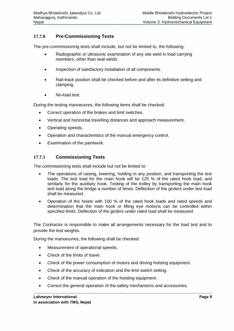
17.7.0 Pre-Commissioning Tests
The pre-commissioning tests shall include, but not be limited to, the following:
Radiographic or ultrasonic examination of any site weld in load carrying members, other than seal welds.
Inspection of satisfactory installation of all components.
Rail-track position shall be checked before and after its definitive setting and clamping.
No-load test.
During the testing manoeuvres, the following items shall be checked:
Correct operation of the brakes and limit switches,
Vertical and horizontal travelling distances and approach measurement,
Operating speeds,
Operation and characteristics of the manual emergency control,
Examination of the paintwork.
17.7.1 Commissioning Tests
The commissioning tests shall include but not be limited to:
The operations of raising, lowering, holding in any position, and transporting the test loads. The test load for the main hook will be 125 % of the rated hook load, and similarly for the auxiliary hook. Testing of the trolley by transporting the main hook test load along the bridge a number of times. Deflection of the girders under test load shall be measured.
Operation of the hoists with 100 % of the rated hook loads and rated speeds and determination that the main hook or lifting eye motions can be controlled within specified limits. Deflection of the girders under rated load shall be measured.
The Contractor is responsible to make all arrangements necessary for the load test and to
provide the test weights.
During the manoeuvres, the following shall be checked:
Measurement of operational speeds.
Check of the limits of travel.
Check of the power consumption of motors and driving hoisting equipment.
Check of the accuracy of indication and the limit switch setting.
Check of the manual operation of the hoisting equipment.
Correct the general operation of the safety mechanisms and accessories.
Madhya Bhotekoshi Jalavidyut Co. Ltd. Maharajgunj, Kathmandu Nepal
Middle Bhotekoshi Hydroelectric Project Bidding Documents Lot 1
Volume 3: Hydromechanical Equipment
Lahmeyer International
in association with TMS, Nepal
Page 10
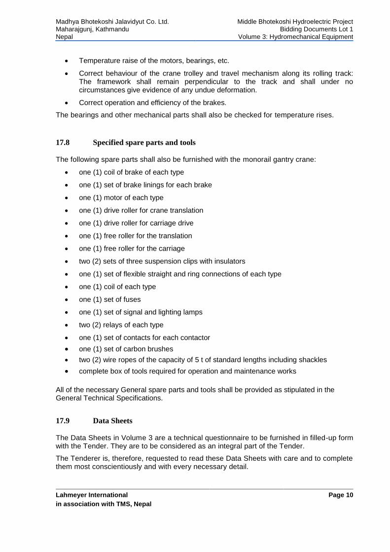
Temperature raise of the motors, bearings, etc.
Correct behaviour of the crane trolley and travel mechanism along its rolling track: The framework shall remain perpendicular to the track and shall under no circumstances give evidence of any undue deformation.
Correct operation and efficiency of the brakes.
The bearings and other mechanical parts shall also be checked for temperature rises.
17.8 Specified spare parts and tools
The following spare parts shall also be furnished with the monorail gantry crane:
one (1) coil of brake of each type
one (1) set of brake linings for each brake
one (1) motor of each type
one (1) drive roller for crane translation
one (1) drive roller for carriage drive
one (1) free roller for the translation
one (1) free roller for the carriage
two (2) sets of three suspension clips with insulators
one (1) set of flexible straight and ring connections of each type
one (1) coil of each type
one (1) set of fuses
one (1) set of signal and lighting lamps
two (2) relays of each type
one (1) set of contacts for each contactor
one (1) set of carbon brushes
two (2) wire ropes of the capacity of 5 t of standard lengths including shackles
complete box of tools required for operation and maintenance works
All of the necessary General spare parts and tools shall be provided as stipulated in the General Technical Specifications.
17.9 Data Sheets
The Data Sheets in Volume 3 are a technical questionnaire to be furnished in filled-up form with the Tender. They are to be considered as an integral part of the Tender.
The Tenderer is, therefore, requested to read these Data Sheets with care and to complete them most conscientiously and with every necessary detail.
Madhya Bhotekoshi Jalavidyut Co. Ltd. Maharajgunj, Kathmandu Nepal
Middle Bhotekoshi Hydroelectric Project Bidding Documents Lot 1
Volume 3: Hydromechanical Equipment
Lahmeyer International GmbH
In association with TMS, Nepal
Page i
LOT 1
VOLUME 3
HYDROMECHANICAL EQUIPMENT
TECHNICAL DATA SHEETS
17: MONORAIL GANTRY CRANE
Table of Contents
17. MONORAIL GANTRY CRANE .................................................................................................................. 1
17.1 MANUFACTURER ....................................................................................................................................... 1
17.2 HOISTING MECHANISM .............................................................................................................................. 1
17.2.1 Main Hoist ........................................................................................................................................ 1
17.3 TRAVELLING MECHANISM .......................................................................................................................... 1
17.3.1 Gantry .............................................................................................................................................. 1
17.3.2 Trolley .............................................................................................................................................. 2
17.4 PAINTING .................................................................................................................................................. 3
17.5 WEIGHTS .................................................................................................................................................. 3
17.6 TRANSPORTATION ..................................................................................................................................... 3
Madhya Bhotekoshi Jalavidyut Co. Ltd. Maharajgunj, Kathmandu Nepal
Middle Bhotekoshi Hydroelectric Project Bidding Documents Lot 1
Volume 3: Hydromechanical Equipment
Lahmeyer International GmbH
In association with TMS, Nepal
Page 1
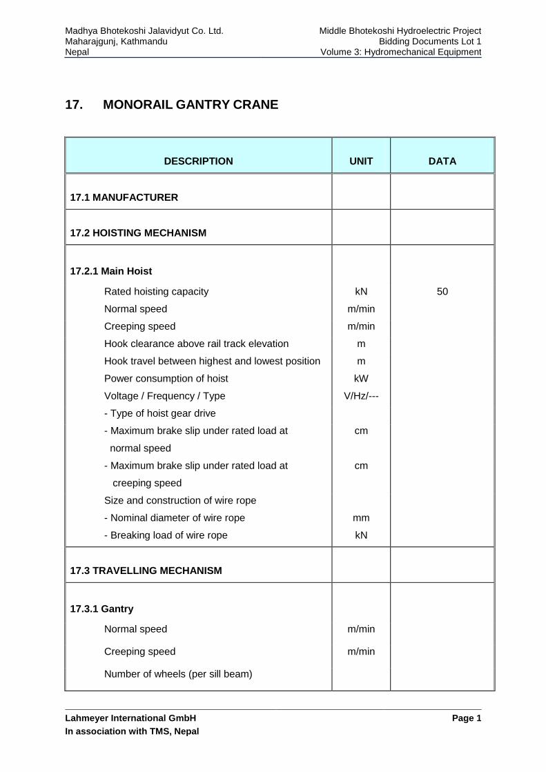
17. MONORAIL GANTRY CRANE
DESCRIPTION
UNIT
DATA
17.1 MANUFACTURER
17.2 HOISTING MECHANISM
17.2.1 Main Hoist
Rated hoisting capacity kN 50
Normal speed m/min
Creeping speed m/min
Hook clearance above rail track elevation m
Hook travel between highest and lowest position m
Power consumption of hoist
Voltage / Frequency / Type
kW
V/Hz/---
- Type of hoist gear drive
- Maximum brake slip under rated load at
normal speed
cm
- Maximum brake slip under rated load at
creeping speed
cm
Size and construction of wire rope
- Nominal diameter of wire rope mm
- Breaking load of wire rope kN
17.3 TRAVELLING MECHANISM
17.3.1 Gantry
Normal speed m/min
Creeping speed m/min
Number of wheels (per sill beam)
Madhya Bhotekoshi Jalavidyut Co. Ltd. Maharajgunj, Kathmandu Nepal
Middle Bhotekoshi Hydroelectric Project Bidding Documents Lot 1
Volume 3: Hydromechanical Equipment
Lahmeyer International GmbH
In association with TMS, Nepal
Page 2
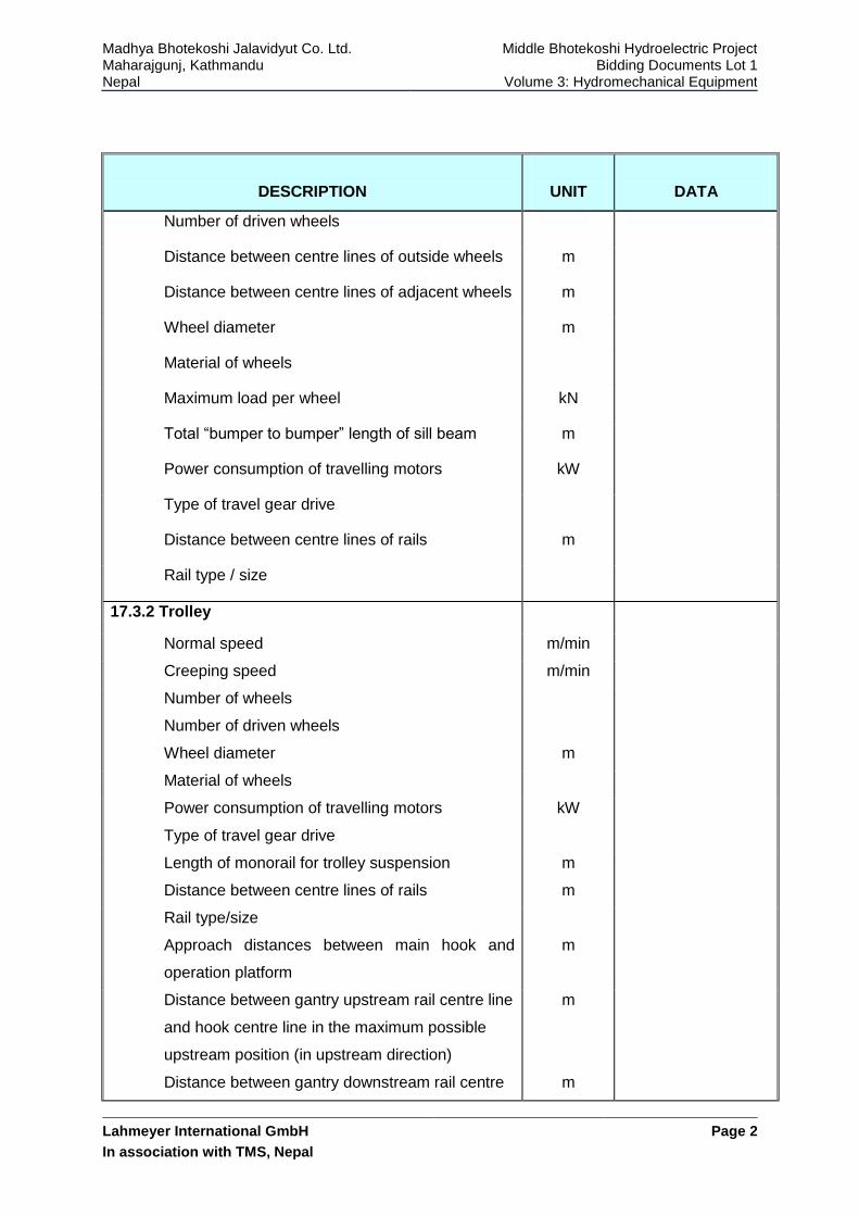
DESCRIPTION
UNIT
DATA
Number of driven wheels
Distance between centre lines of outside wheels m
Distance between centre lines of adjacent wheels m
Wheel diameter m
Material of wheels
Maximum load per wheel kN
Total “bumper to bumper” length of sill beam m
Power consumption of travelling motors kW
Type of travel gear drive
Distance between centre lines of rails m
Rail type / size
17.3.2 Trolley
Normal speed m/min
Creeping speed m/min
Number of wheels
Number of driven wheels
Wheel diameter m
Material of wheels
Power consumption of travelling motors kW
Type of travel gear drive
Length of monorail for trolley suspension
Distance between centre lines of rails
m
m
Rail type/size
Approach distances between main hook and
operation platform
m
Distance between gantry upstream rail centre line
and hook centre line in the maximum possible
upstream position (in upstream direction)
Distance between gantry downstream rail centre
m
m
Madhya Bhotekoshi Jalavidyut Co. Ltd. Maharajgunj, Kathmandu Nepal
Middle Bhotekoshi Hydroelectric Project Bidding Documents Lot 1
Volume 3: Hydromechanical Equipment
Lahmeyer International GmbH
In association with TMS, Nepal
Page 3
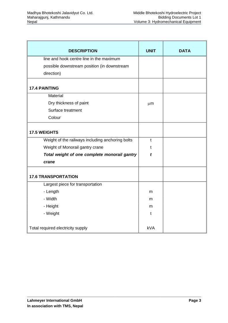
DESCRIPTION
UNIT
DATA
line and hook centre line in the maximum
possible downstream position (in downstream
direction)
17.4 PAINTING
Material
Dry thickness of paint
Surface treatment
Colour
m
17.5 WEIGHTS
Weight of the railways including anchoring bolts t
Weight of Monorail gantry crane
Total weight of one complete monorail gantry
crane
t
t
17.6 TRANSPORTATION
Largest piece for transportation
- Length m
- Width m
- Height m
- Weight
Total required electricity supply
t
kVA