amd iv ms gpa-072-15 supervisory control and data...
TRANSCRIPT
Multi-Step Bid GPA-072-15 Supervisory Control and Data Acquisition (SCADA) System D. Fejeran Page 2 of 12
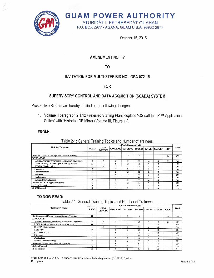
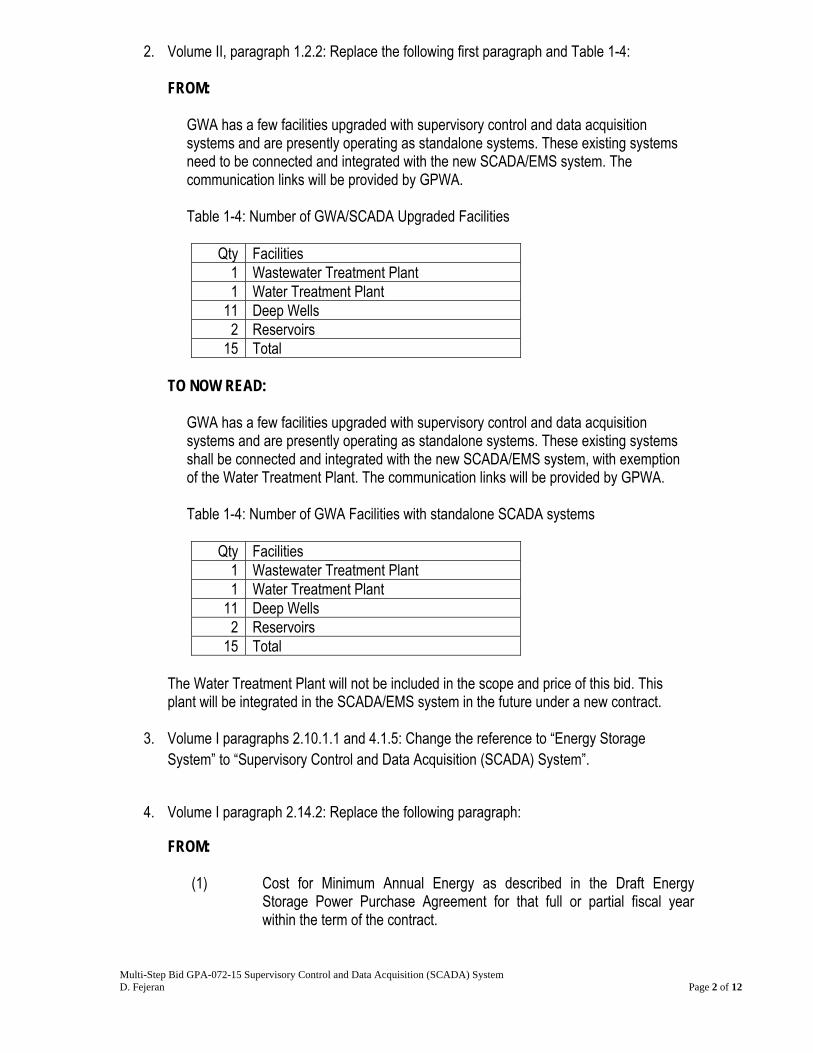
2. Volume II, paragraph 1.2.2: Replace the following first paragraph and Table 1-4:
FROM:
GWA has a few facilities upgraded with supervisory control and data acquisition systems and are presently operating as standalone systems. These existing systems need to be connected and integrated with the new SCADA/EMS system. The communication links will be provided by GPWA.
Table 1-4: Number of GWA/SCADA Upgraded Facilities
Qty Facilities
1 Wastewater Treatment Plant 1 Water Treatment Plant
11 Deep Wells 2 Reservoirs
15 Total TO NOW READ:
GWA has a few facilities upgraded with supervisory control and data acquisition systems and are presently operating as standalone systems. These existing systems shall be connected and integrated with the new SCADA/EMS system, with exemption of the Water Treatment Plant. The communication links will be provided by GPWA. Table 1-4: Number of GWA Facilities with standalone SCADA systems
Qty Facilities
1 Wastewater Treatment Plant 1 Water Treatment Plant
11 Deep Wells 2 Reservoirs
15 Total The Water Treatment Plant will not be included in the scope and price of this bid. This plant will be integrated in the SCADA/EMS system in the future under a new contract.
3. Volume I paragraphs 2.10.1.1 and 4.1.5: Change the reference to “Energy Storage System” to “Supervisory Control and Data Acquisition (SCADA) System”.
4. Volume I paragraph 2.14.2: Replace the following paragraph:
FROM:
(1) Cost for Minimum Annual Energy as described in the Draft Energy Storage Power Purchase Agreement for that full or partial fiscal year within the term of the contract.

Multi-Step Bid GPA-072-15 Supervisory Control and Data Acquisition (SCADA) System D. Fejeran Page 3 of 12
TO NOW READ:
(1) Cost of the Software.
5. Volume II, paragraph 1.2.1: Delete the following last two sentences in the first paragraph:
However, due to funding limitations, GWA has broken down Phase A into multiple implementations. The initial SCADA Phase A-1 will consist of a new central SCADA/EMS system connected and integrated with existing and new SCADA upgraded water and wastewater facilities.
6. Volume II, paragraph 1.2.1: Replace the following sentence of second paragraph:
FROM:
The GWA SCADA Master Plan provides requirements inclusive for this Bid. TO NOW READ:
The GWA SCADA Master Plan is provided for Contractor information only.
7. Volume II, paragraph 1.2.2, third bullet item: Change the second sentence: FROM:
The system consisted of a PLC and communication equipment at each site and one master SCADA server. This system does not interact with other systems.
TO NOW READ:
The system consisted of a PLC and communication equipment at each site and one master SCADA server that will be de-commissioned.
8. Volume II, paragraph 1.2.3: Replace the following:
FROM:
GWA has several upcoming capital improvement projects that will be upgrading 120 additional water and wastewater facilities with programmable logic controllers (or remote terminal units), communications, and field instrumentation. These new SCADA upgraded facilities need to be connected and integrated with the new SCADA/EMS system. The communication links will be provided by GPWA.
Table 1-5: Number of GWA Facilities Scheduled for SCADA Upgrades
Qty Facilities
77 Wastewater Pump Stations 33 Deep Wells

Multi-Step Bid GPA-072-15 Supervisory Control and Data Acquisition (SCADA) System D. Fejeran Page 4 of 12
5 Reservoirs 3 Water Booster Pump Stations 1 Master Meter 1 Pressure Regulating Valve
120 Total
TO NOW READ:
GWA has several capital improvement projects that will be upgrading 67 additional water and wastewater facilities with programmable logic controllers (or remote terminal units), communications, and field instrumentation. These new SCADA upgraded facilities shall be connected and integrated with the new SCADA/EMS system. The communication links will be provided by GPWA.
Table 1-5a: Number of New GWA Facilities Scheduled for SCADA Upgrades
Qty Facilities
20 Wastewater Pump Stations 33 Deep Wells 5 Reservoirs 3 Water Booster Pump Stations 5 Master Meter 1 Pressure Regulating Valve
67 Total
The planned build-out of the GWA SCADA Master Plan for the remaining 331 water and wastewater facilities will be priced in the bid as an additive bid item. Should GWA choose to award the additive bid, the Contractor shall add the database points, SCADA screens and reports for 331 future facilities in the new SCADA/EMS system. The negotiations, physical connections and integrations of 331 future facilities to the SCADA/EMS system shall be performed in the future under a new contract. Table 1-5b: Number of Future GWA Facilities scheduled for SCADA
Qty Facilities 58 Wastewater Pump Stations 76 Deep Wells 32 Reservoirs 33 Water Booster Pump Stations 60 Master Meter 72 Pressure Regulating Valve
331 Total
9. Volume II, section 1.3: Add a third paragraph using the following:

Multi-Step Bid GPA-072-15 Supervisory Control and Data Acquisition (SCADA) System D. Fejeran Page 5 of 12
The communications shall include support for existing GWA video systems to provide remote access to CCTV/security equipment. Large stations are expected to store video locally and allow limited access to files remotely. Smaller stations shall provide data management to accept images produced by local video system and store in data warehouse area associated with the affected site for retrieval by operations staff.
10. Volume II, paragraph 1.4.2: Change first two sentences of third paragraph: FROM:
Data in the new SCADA/EMS system shall be geographically referenced. Contractor shall bring in the map from the ArcMap GIS into the new SCADA/EMS system to maintain one single consistent map.
TO NOW READ:
Data in the new SCADA/EMS system shall be geographically referenced. Contractor shall use the maps from the ArcGIS for the new SCADA/EMS system to maintain one single consistent map.
11. Volume II, paragraph 3.1.E.d: Replace the following: FROM:
Delivery of a Multi-Screen Video Wall system for the GWA Systems Control Center
TO NOW READ: Delivery of two (2) each wall-mounted 85” LED 2160p 4K Ultra HDTV
12. Volume II, paragraph 3.1.F.g: Replace the following: FROM:
Complete and seamless integration and installation of CONTRACTOR-supplied Multi-Screen Video Wall system for the GWA Systems Control Center
TO NOW READ: Complete and seamless integration and installation of two (2) each CONTRACTOR-supplied wall-mounted 85” LED 2160p 4K Ultra HDTV into the operator stations with the ability to drive the HDTV image from any operator station.
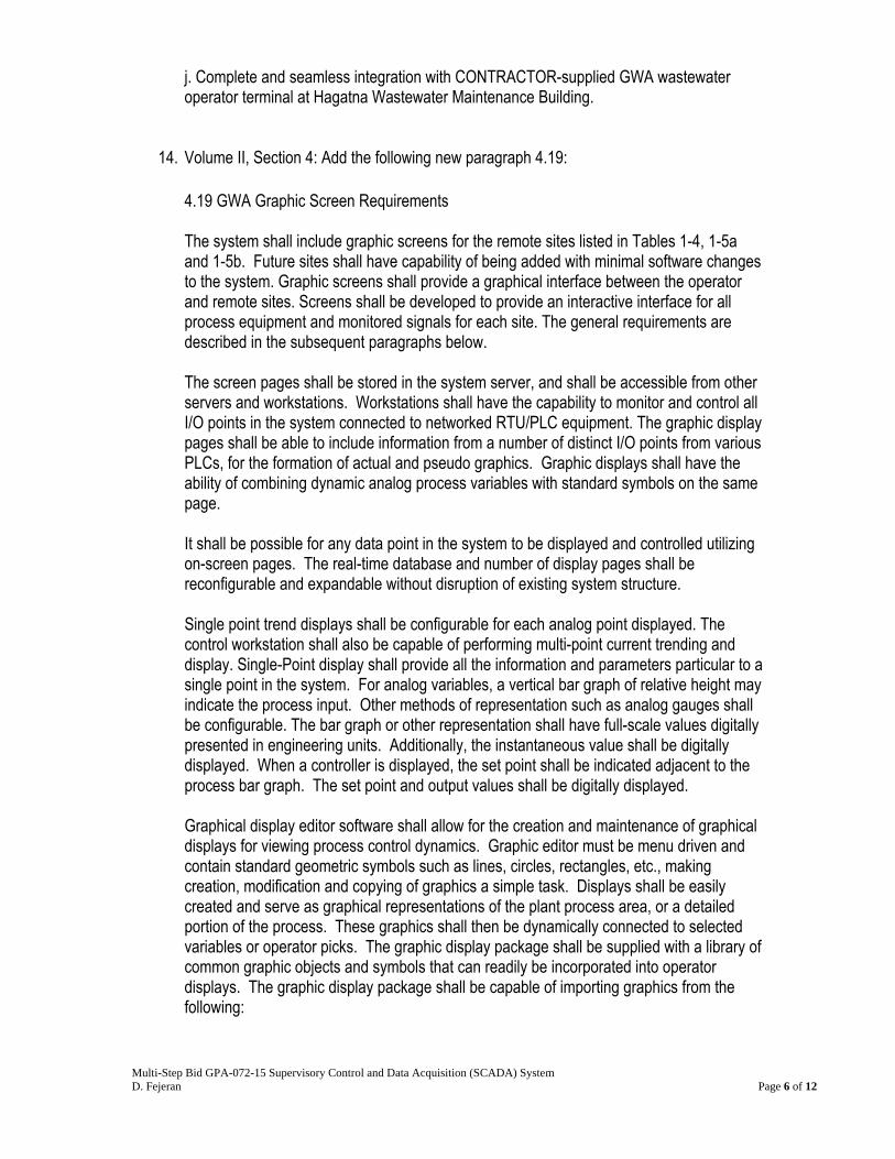
13. Volume II, paragraph 3.1.F: Add the following new item (j):
Multi-Step Bid GPA-072-15 Supervisory Control and Data Acquisition (SCADA) System D. Fejeran Page 6 of 12
j. Complete and seamless integration with CONTRACTOR-supplied GWA wastewater operator terminal at Hagatna Wastewater Maintenance Building.
14. Volume II, Section 4: Add the following new paragraph 4.19: 4.19 GWA Graphic Screen Requirements The system shall include graphic screens for the remote sites listed in Tables 1-4, 1-5a and 1-5b. Future sites shall have capability of being added with minimal software changes to the system. Graphic screens shall provide a graphical interface between the operator and remote sites. Screens shall be developed to provide an interactive interface for all process equipment and monitored signals for each site. The general requirements are described in the subsequent paragraphs below. The screen pages shall be stored in the system server, and shall be accessible from other servers and workstations. Workstations shall have the capability to monitor and control all I/O points in the system connected to networked RTU/PLC equipment. The graphic display pages shall be able to include information from a number of distinct I/O points from various PLCs, for the formation of actual and pseudo graphics. Graphic displays shall have the ability of combining dynamic analog process variables with standard symbols on the same page. It shall be possible for any data point in the system to be displayed and controlled utilizing on-screen pages. The real-time database and number of display pages shall be reconfigurable and expandable without disruption of existing system structure. Single point trend displays shall be configurable for each analog point displayed. The control workstation shall also be capable of performing multi-point current trending and display. Single-Point display shall provide all the information and parameters particular to a single point in the system. For analog variables, a vertical bar graph of relative height may indicate the process input. Other methods of representation such as analog gauges shall be configurable. The bar graph or other representation shall have full-scale values digitally presented in engineering units. Additionally, the instantaneous value shall be digitally displayed. When a controller is displayed, the set point shall be indicated adjacent to the process bar graph. The set point and output values shall be digitally displayed. Graphical display editor software shall allow for the creation and maintenance of graphical displays for viewing process control dynamics. Graphic editor must be menu driven and contain standard geometric symbols such as lines, circles, rectangles, etc., making creation, modification and copying of graphics a simple task. Displays shall be easily created and serve as graphical representations of the plant process area, or a detailed portion of the process. These graphics shall then be dynamically connected to selected variables or operator picks. The graphic display package shall be supplied with a library of common graphic objects and symbols that can readily be incorporated into operator displays. The graphic display package shall be capable of importing graphics from the following:
Multi-Step Bid GPA-072-15 Supervisory Control and Data Acquisition (SCADA) System D. Fejeran Page 7 of 12
Other drawing packages such as Microstation, and AutoCAD. Microsoft Windows clipboard Objects created by other Microsoft Windows applications via OLE 2.0 or later. Status displays shall indicate the status of discrete contact pairs such as on/off or open/closed. The status text shall be selected during configuration to allow customization to the process. Sequences shall be displayable using status display pages. These shall provide the capability for Owner’s personnel to incorporate text to guide the operator in making control decisions. Up to 16 discrete points shall be displayed. In the active state, text shall be displayed in red. In the inactive state, the text shall be displayed in white. Parameter displays shall indicate the value of selected points in digital form. The status may originate from anywhere in the system database and may be changed by the operator from this display. Each high-resolution trend display shall be made up of a minimum of 240 samples on a horizontal time base. Sampling frequency shall be adjustable from 1 sec. to 60 min. for a time basis of 40 minutes to 1 month, full scale. Resolution of the vertical scale shall be 0.5 percent of range or better. Display range shall be user selectable for each point. A cursor shall be provided to assist in reading values of points along with the time base. Operator control of the cursor shall be accomplished from the keyboard or with the mouse. The identification of points in trend, current values, value, time and data represented by the position of the cursor, engineering units measurement, range and type of value recorded shall be clearly indicated in digital form on each display. The system shall be capable of collecting and storing historical data in files on the Data Historian system hard disk as described elsewhere in this bid. The Data Historian Server and any Workstation shall be capable of displaying any of the historical points. All alarms detected in the instruments communicating with the workstations shall be annunciated both visually on the operator’s CRT display and audibly via the operator’s computer sound system. Upon detection, the tag name of the point in alarm shall turn red and begin blinking. Report editor shall be provided that supports the development of a variety of formats to present system data (digital or analog). The report editor shall allow the selection of data points, range of data and allow calculations for Max/Min/Avg and similar values. Some examples (not specific requirements but supporting information related to the type of graphic screens being described) of graphic screens are provided for reference: Figure 4-2: Graphic Screen Example 1

Multi-Step Bid GPA-072-15 Supervisory Control and Data Acquisition (SCADA) System D. Fejeran Page 8 of 12
Figure 4-2: Graphic Screen Example 2

Multi-Step Bid GPA-072-15 Supervisory Control and Data Acquisition (SCADA) System D. Fejeran Page 9 of 12
15. Appendix A Bid Checklist: Replace the following third line item. Amended Document Receipt Checklist form is attached.
FROM:
Volume III: Energy Storage Contract (Draft) TO NOW READ:
Volume III: Supervisory Control and Data Acquisition (SCADA) System Contract (Draft)
16. Appendix P: Replace the system sizing for the following MMI/Consoles:
FROM:
System Sizing Initial Sizing Ultimate Sizing
GPA GWA GPA GWA No. of dispatcher consoles-local 4-21” LCD
4 4 4
No. of dispatcher consoles-local 3-21” LCD
0 0
No. of dispatcher consoles-local 2*21” LCD
2 4 2 4
No. of dispatcher consoles-local 1-21” LCD
1 1
No. of Remote PC Consoles (Software only)
8 16
No. of Maintenance Consoles 2-21” LCD
2 3 2 4
No. of Engineering Consoles 2-21” LCD
2 2
No. of Projection Mapboard Drivers (Single screen)
3 3 3 3
No. of Map-board Status Points 600 To be determined
600 To be determined
No. of Digital Display (i.e. Time, Frequency, Voltage, Windspeed)
6 1 6 1
TO NOW READ:
System Sizing Initial Sizing Ultimate Sizing
GPA GWA GPA GWA No. of dispatcher consoles-local 4-27” LCD
4 4 0
No. of dispatcher consoles-local 3-27” LCD
0 7 0 7

Multi-Step Bid GPA-072-15 Supervisory Control and Data Acquisition (SCADA) System D. Fejeran Page 10 of 12
No. of dispatcher consoles-local 2-27” LCD
2 0 2 0
No. of dispatcher consoles-local 1-27” LCD
1 1
No. of Remote PC Consoles 2-27” LCD
4 4
No. of Remote PC Consoles (Software only)
8 6 16 12
No. of Maintenance Consoles 3-27” LCD
3 3
No. of Maintenance Consoles 2-27” LCD
2 0 2 0
No. of Engineering Consoles 2-27” LCD
1 1
No. of Projection Mapboard Drivers (Single screen)
3 3 3 3
No. of Map-board Status Points 600 To be determined
600 To be determined
No. of Digital Display (i.e. Time, Frequency, Voltage, Windspeed)
6 1 6 1
17. Appendix P: Replace the system sizing for the following GWA Network Model:
FROM:
System Sizing Initial Sizing Ultimate Sizing GPA GWA GPA GWA
GWA Network Model Water System:
No. of Deep Wells 42 124 No. of Water Treatment Plants 0 6 No. of Springs 0 5 No. of Water Booster Pump Stations 3 40 No. of Reservoirs 7 39 No. of System Meters 1 65 No. of Pressure Regulating Valves 1 73 No. of Water Lines No. of Areas/Zones
Wastewater System: No. of Wastewater Treatment Plants 1 2 No. of Wastewater Sewer Pump Stations
77 78
No. of Wastewater Lines No. of Areas/Zones
Multi-Step Bid GPA-072-15 Supervisory Control and Data Acquisition (SCADA) System D. Fejeran Page 11 of 12
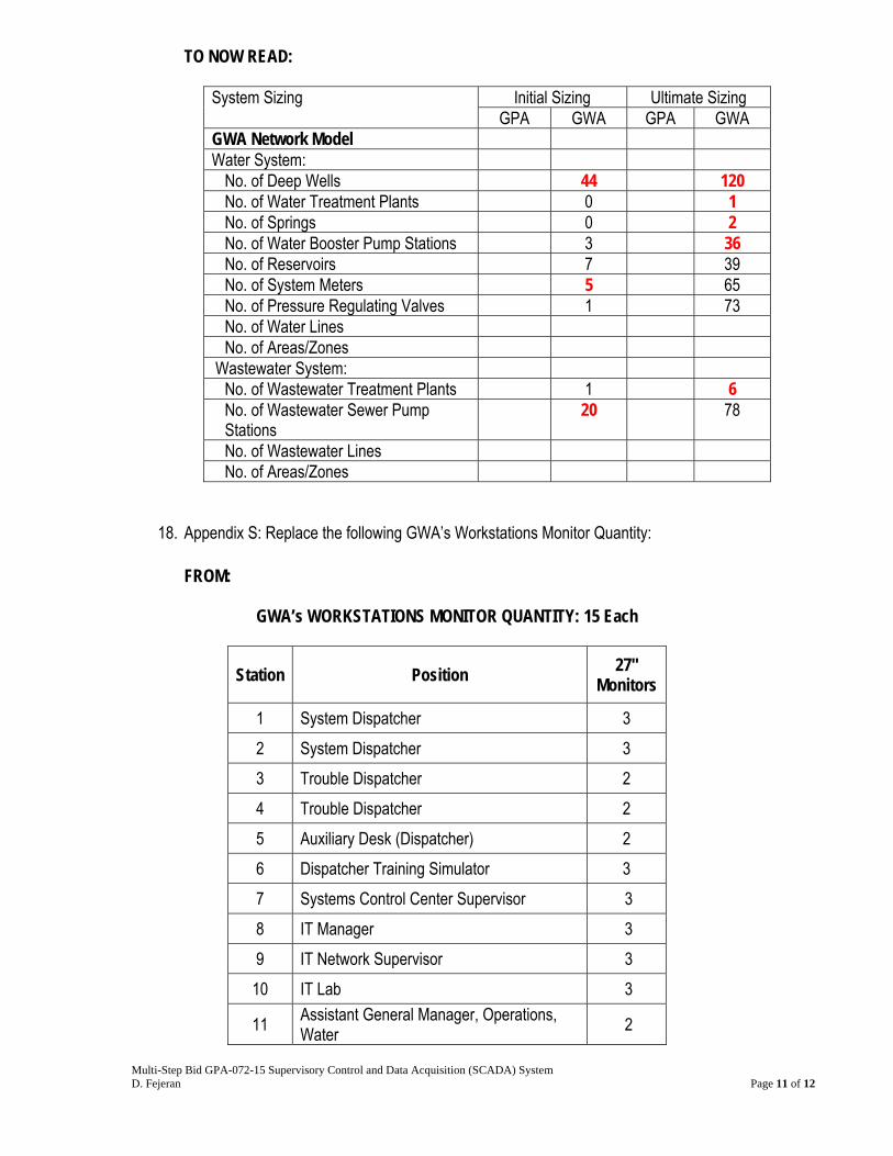
TO NOW READ:
System Sizing Initial Sizing Ultimate Sizing GPA GWA GPA GWA
GWA Network Model Water System:
No. of Deep Wells 44 120 No. of Water Treatment Plants 0 1 No. of Springs 0 2 No. of Water Booster Pump Stations 3 36 No. of Reservoirs 7 39 No. of System Meters 5 65 No. of Pressure Regulating Valves 1 73 No. of Water Lines No. of Areas/Zones
Wastewater System: No. of Wastewater Treatment Plants 1 6 No. of Wastewater Sewer Pump Stations
20 78
No. of Wastewater Lines No. of Areas/Zones
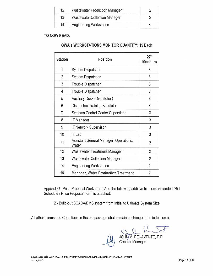
18. Appendix S: Replace the following GWA’s Workstations Monitor Quantity:
FROM:
GWA’s WORKSTATIONS MONITOR QUANTITY: 15 Each
Station Position 27"
Monitors
1 System Dispatcher 3
2 System Dispatcher 3
3 Trouble Dispatcher 2
4 Trouble Dispatcher 2
5 Auxiliary Desk (Dispatcher) 2
6 Dispatcher Training Simulator 3
7 Systems Control Center Supervisor 3
8 IT Manager 3
9 IT Network Supervisor 3
10 IT Lab 3
11 Assistant General Manager, Operations, Water
2