amba axi 29 3_2015
TRANSCRIPT

AMBA AXI PROTOCOL
CONTENTS
Key Features
Objectives
Channel Architecture
Basic Transaction
Signal Descriptions
Addressing Options
Channel Handshake

AMBA AXI PROTOCOL
Key Features
• Separate address/ control and data phases
• Separate read and write channels to enable low-cost
Direct Memory Access
• Burst-based transactions with only start address issued
• Ability to issue multiple outstanding address
• Out – of – order (OOO) transaction completion
• Register slice support for high frequency operation

AMBA AXI PROTOCOL
Objectives
• Be suitable for high-bandwidth and low-latency
designs
• Enable high-frequency operation
• Fit for devices with high initial latency
• Provide flexibility of interconnect architectures
• Be backward-compatible with existing AHB and
APB interfaces.

AMBA AXI PROTOCOL
Channel Architectures
AXI Master AXI Slave
Write Address/ Control
AWREADY
Read Address/ Control
ARREADY
Read Address/ Control
Write data
WREADY
Read data
RREADY
Write Responce
BREADY
Five unidirectional channels
AMBA AXI PROTOCOL
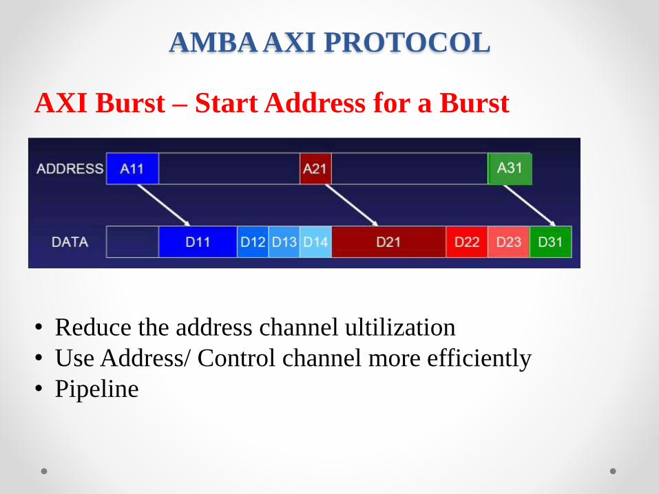
AXI Burst – Start Address for a Burst
• Reduce the address channel ultilization
• Use Address/ Control channel more efficiently
• Pipeline

AMBA AXI PROTOCOL
Outstanding Transactions
• Decouple the fixed link between address and data
• Enable parallel processing of transactions
AMBA AXI PROTOCOL
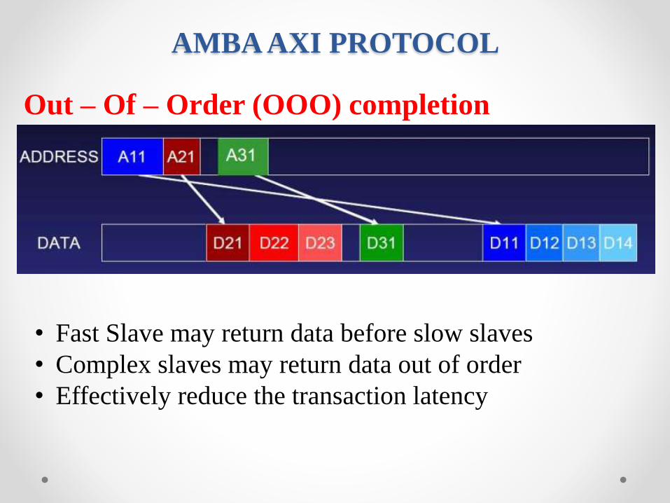
Out – Of – Order (OOO) completion
• Fast Slave may return data before slow slaves
• Complex slaves may return data out of order
• Effectively reduce the transaction latency

AMBA AXI PROTOCOL
Data Interleaving
• Data within a burst is always in order
• Each transaction has a unique ID

AMBA AXI PROTOCOL
Register slices support for high frequency operation ?
Allows maximum frequency of
operation by matching channel
latency to channel delay

AMBA AXI PROTOCOL
Basic TransactionsRead Burst Example
4-beat read burst

AMBA AXI PROTOCOL
Basic TransactionsOverlapping Read Burst Example
3-beat read burst + 2-beat read burst

AMBA AXI PROTOCOL
Basic TransactionsWrite Burst Example
4-beat write burst

AMBA AXI PROTOCOL
Signals DescriptionsSignals of Write Address Channel

AMBA AXI PROTOCOL
Signals DescriptionsSignals of Write Data Channel

AMBA AXI PROTOCOL
Signals DescriptionsSignals of Write Response Channel

AMBA AXI PROTOCOL
Signals DescriptionsSignals of Read Address Channel

AMBA AXI PROTOCOL
Signals DescriptionsSignals of Read Data Channel
AMBA AXI PROTOCOL
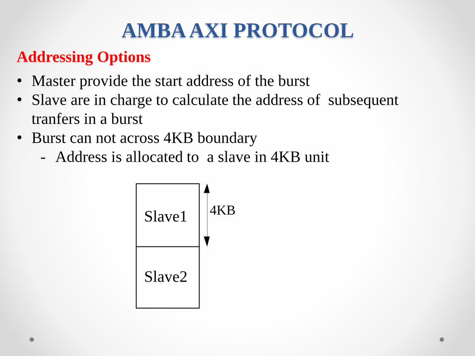
Addressing Options
• Master provide the start address of the burst
• Slave are in charge to calculate the address of subsequent
tranfers in a burst
• Burst can not across 4KB boundary
- Address is allocated to a slave in 4KB unit
Slave1
Slave2
4KB

AMBA AXI PROTOCOL
Addressing Options
• Burst length specifies the number of data
tranfers that occur within each a burst.
• For wrapping burst, the length of the burst
must be 2, 4, 8 or 16 tranfers.
Burst Length

AMBA AXI PROTOCOL
Addressing Options
• Burst size specifies the maximum number of
data bytes to tranfer in each beat, within a
burst.
• For incrementing and wrapping bursts and
tranfer sizes are smaller than the data bus width
- Tranfers are on different byte lanes for
each burst ( driving by write strobe)
• For fixed bursts
- Address remains contant within a burst
- Every tranfer use the same byte lane
Burst Size

AMBA AXI PROTOCOL
Addressing Options
• Fixed burst
- Address remains the same for every tranfer in the burst
- Repeat access to the same location
• Incrementing burst
- Address for the each tranfer in the burst is an increment of the previous address
- The increment value depends on the size of the tranfer
• Wrapping burst
- The start address must be aligned to the size of the tranfer
- The length of the burst must be 2, 4, 8 or 16.
Burst Type

AMBA AXI PROTOCOLAddressing Options
• Start Address : the start address issued by the master
• Number_bytes : the maximum number of bytes in each data
tranfer
• Data_bus_bytes : the number of byte lanes in the data bus
• Aligned_address : the aligned version of the start address
• Burst_length : the total number of data tranfers within a burst
• Address_N : the address of tranfer N within a burst. N is an
integer from 2-16
• Wrap_boundary : the lowest address within a wrapping burst
• INT(x) : the rounded-down integer value x
Burst Adress

AMBA AXI PROTOCOLAddressing Options
• Start Address = ADDR
• Number_bytes = 2^SIZE
• Burst_length = LEN + 1
• Aligned_address = (INT(Start_address / Number_Bytes)) x Number_Bytes
• Address1 = Start_Address
• Address_N = Aligned_address + (N-1) x Number_Bytes
For wrapping burst, the wrap_boundary variable is extended to account for the
wrapping boundary :
• Wrap_boundary = (INT(Start_address / (Number_Bytes x Burst_length))) x
(Number_Bytes x Burst_length)
If Address_N = wrap_boundary + (Number_Bytes x Burst_length), use this equation
• Address_N = Wrap_boundary.
Burst Adress - formulas

AMBA AXI PROTOCOLAddressing Options
• Start_Address = 0x4a ; Burst_size = 3’b010;
• Number_Bytes = 2^SIZE = 2^2 = 4
• Burst_length = 4
• Aligned_address = (INT(Start_address / Number_Bytes)) x Number_Bytes
= (INT( 0x4a / 4) x 4
= 0x48
Example Wrapping Address
• Address_1 = Start_address = 0x4a• Address_2 = Aligned_address + (N-1) x Number_Bytes
= 0x48 + (2-1) x 4= 0x4c
• Address_3 = 0x48 + (3-1) x 4= 0x50
• Wrap_boundary = (INT(Start_address / (Number_bytes x Burst_length))) x (Number_bytes x Burst_length)
= (INT( 0x4a / (4x4)) x (4x4)= 0x40
AMBA AXI PROTOCOL
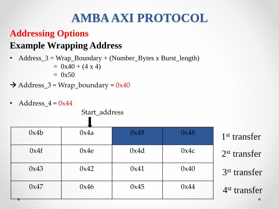
Addressing Options
Example Wrapping Address
• Address_3 = Wrap_Boundary + (Number_Bytes x Burst_length)
= 0x40 + (4 x 4)
= 0x50
Address_3 = Wrap_boundary = 0x40
• Address_4 = 0x44
0x4b 0x4a 0x49 0x48
0x4f 0x4e 0x4d 0x4c
0x43 0x42 0x41 0x40
0x47 0x46 0x45 0x44
1st transfer
2st transfer
3st transfer
4st transfer
Start_address
AMBA AXI PROTOCOL
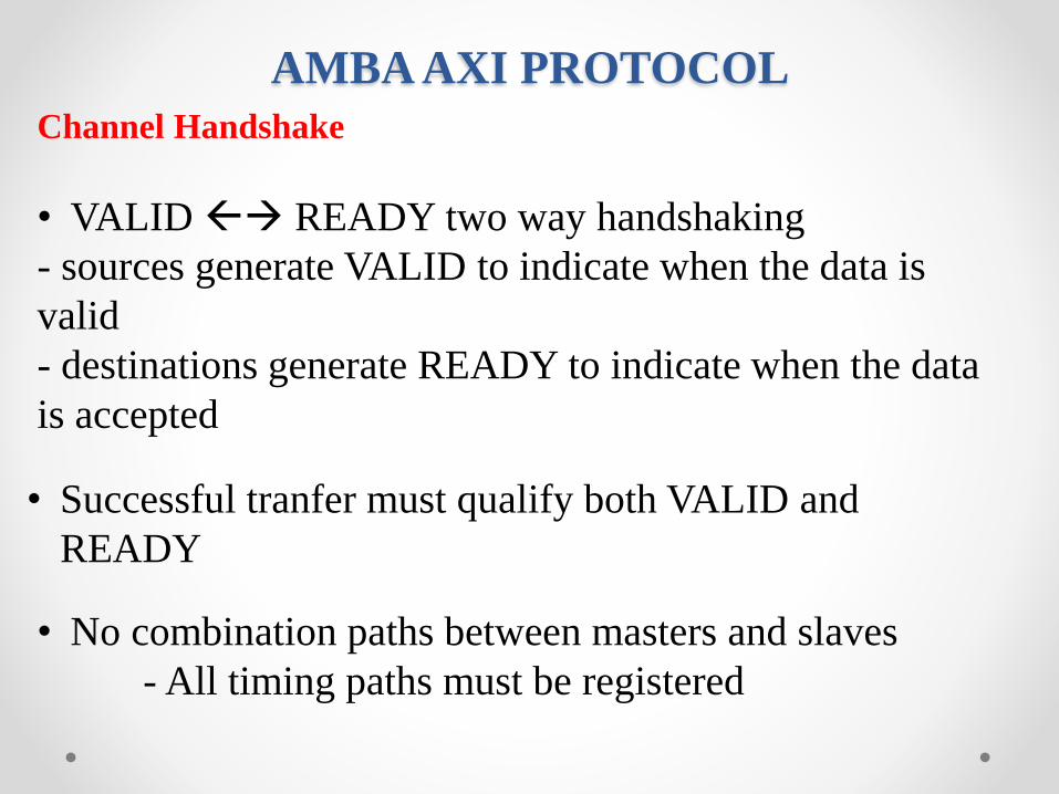
Channel Handshake
• VALID READY two way handshaking
- sources generate VALID to indicate when the data is
valid
- destinations generate READY to indicate when the data
is accepted
• Successful tranfer must qualify both VALID and
READY
• No combination paths between masters and slaves
- All timing paths must be registered

AMBA AXI PROTOCOL
Channel Handshake
Handshaking Timing Diagram
1.VALID before READY handshake.
When the destinations drives the
READY signal high, indicating that it
accepts the data or control information
2.READY before VALID handshake.
This indicates that the destination can
accept the data or control information in a
single cycle
3.READY with VALID handshake.
Both the source and destination happen
to indicate in the same cycle
AMBA AXI PROTOCOL
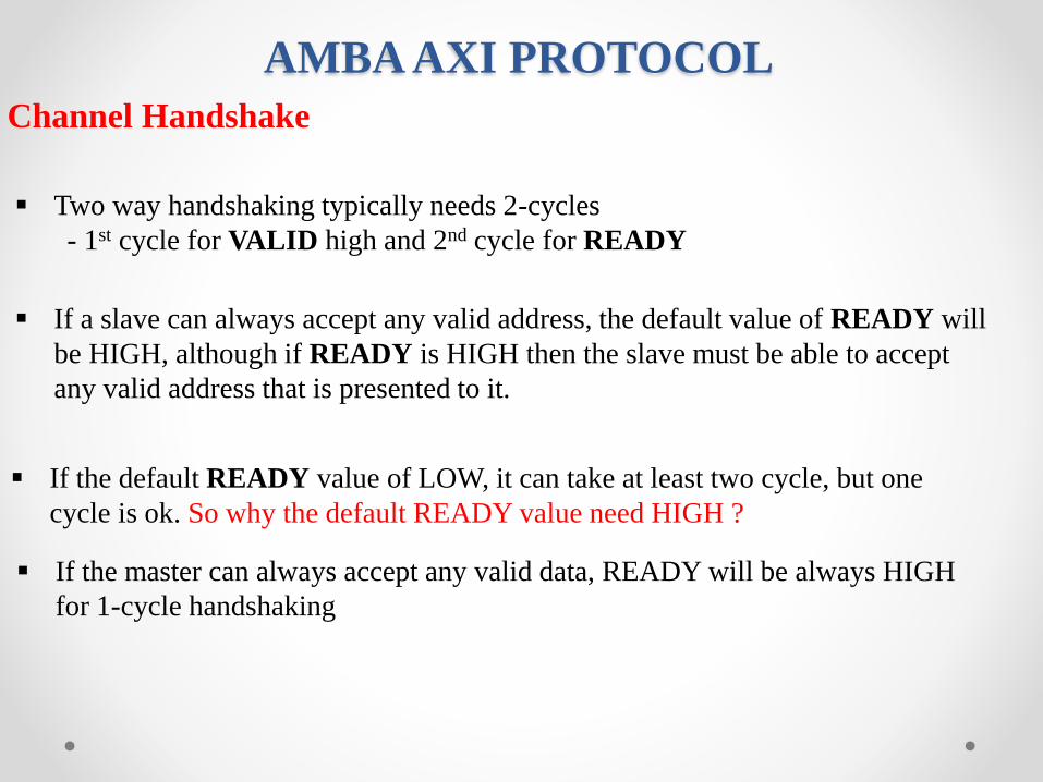
Channel Handshake
Two way handshaking typically needs 2-cycles
- 1st cycle for VALID high and 2nd cycle for READY
If a slave can always accept any valid address, the default value of READY will
be HIGH, although if READY is HIGH then the slave must be able to accept
any valid address that is presented to it.
If the default READY value of LOW, it can take at least two cycle, but one
cycle is ok. So why the default READY value need HIGH ?
If the master can always accept any valid data, READY will be always HIGH
for 1-cycle handshaking

AMBA AXI PROTOCOL
Channel Handshake
Dependency in Read Transactions
ARVALID RVALID
ARREADY RREADY
can wait
must wait
• A slave can wait for ARVALID before asserting ARREADY
• A slave must wait for ARVALID & ARREADY before
asserting RVALID
• A master can wait for RVALID before asserting RREADY

AMBA AXI PROTOCOL
Channel Handshake
Dependency in Write Transactions
• A slave can wait for AWVALID, WVALID or both before asserting
AWREADY
• A slave can wait for AWVALID, WVALID or both before asserting
WREADY
• A slave must wait for WVALID & WREADY before asserting BVALID
• A master can wait for BVALID before asserting BREADY
AWVALID WVALID
AWREADY WREADY
can wait
must wait
BVALID
BREADY
IMPORTANT NOTE :
Master must not wait for
AWREADY to be asserted before
driving WVALID. This could cause a
deadlock condition if the slave is
conversely waitting for WVALID
before asserting AWREADY