am series direct coupled actuator - supercontrols … · am series direct coupled actuator ... 24...
TRANSCRIPT

80
F203
58 /
5 4
3 2
1 -0
1/04
-10M
-IG-S
ubje
ct to
cha
nge.
© B
elim
o Ai
rcon
trols
(USA
), In
c.
AM Series Direct Coupled Actuator
Areas of Application
Versatile and Powerful Minimum 160 in-lb torque in a compact package.
For damper areas up to 40 sq-ft*.
®
3/4" minAV1
1
2
3
4
5
5
4
1
3
1
Kit specification2 ball joints KG8 (20204)Spacer (22127)Crank arm (22165)Front mountingbracket (22167)Rear mountingbracket (20346)
2 Screws M6 x 16 (43600)7 Self-tapping screws 4,2 x 13 (43990)
2
Direct Coupledup to 3/4” standard shaftsor Jackshafts to 1.05”(with K4-1 Clamp)
Mounting withlinkage (ZG-AMaccessory kit)
Short shaftmounting (withAV1 clamp)
Fits Jackshafts also.
Torque: 160 in-lb 133in-lb
Power supply: 24 VAC/DC
Control signal: on-off/floating On/Off
Control signal: proportional 2 to 10 VDC
Control signal: 0… 135Ω or Honeywell®
Electronic Series 900 to 20 V phasecut
Feedback: 2 to 10 VDC
Running time: 150 sec constant
Running time: 110 to 150 sec load dependent
Running time: 100 to 200 sec load dependent
Running time: 16 to 19 sec load dependent
External direction of rotation switch
Conduit fitting
Appliance cable
Built-in auxiliary switches
UL listed, CSA certified, CE
Auxiliary switches and feedback potentiometer ....................................(p.88- 90)Installation instructions ......(p. 91–95) General wiring ..............(p. 93) Start-up and checkout (p. 96)
* 4 in-lb/ft2 damper torque loading. Parallel blade. No edge seals.
AM
24 U
S (p
. 82)
AM
24-S
US
(p. 8
2)
AM
24-S
R U
S (p
. 84)
SM
24-S
US
(p. 8
8)
AM
24-P
C U
S (p
. 86)
AM Series – at a glance

81
F203
58 /
5 4
3 2
1 -0
1/04
-10M
-IG-S
ubje
ct to
cha
nge.
© B
elim
o Ai
rcon
trols
(USA
), In
c.
AM
AM Series Direct Coupled Actuator®
LISTED94D5TEMP. IND ®. EQUIP.
UL
20% more torque than SM.
Fits inside 4” damper frame.
Full stroke overload protection.
Electronic deadband for accuracy and stability (proportional models).
Easy direct coupled mounting, including jackshafts to 1.05”.
Check damper position with clear position indicator.
Set actuator to compensate for damper seal wear andcompression (proportional models).
Constant running time aids control loop tuning (proportional models).
Added flexibility with built-in mechanical stops.
Fully adjustable, built-in auxiliary switches (AM24-S US only).
Auxiliary switch add-on mounts on clamp,includes conduit fitting (SA1 US, SA2 US).
Push button manual override
Easily reverse control direction with switch on housing
3’ cable speeds installations
Micro processor controlled Brushless DC Motor
The Belimo Difference
Customer Commitment.Extensive product range. Competitive project pricing. Application assistance. Same-day shipments. Free technical support. Five year warranty.
Low Installation and Life-Cycle Cost.Easy installation. Accuracy and repeatability. Low power consumption. No maintenance.
Long Service Life.Components tested before assembly. Every product tested before shipment. 20+ years direct coupled actuator design.
A CLOSER LOOK…
©

82
F203
58 /
5 4
3 2
1 -0
1/04
-10M
-IG-S
ubje
ct to
cha
nge.
© B
elim
o Ai
rcon
trols
(USA
), In
c.
AM24 (-S) US On-off/ floating point control, non-spring return, direct coupled, 24 V
ApplicationFor on-off and floating point control of dampers in HVAC sys-tems. Actuator sizing should be done in accordance with thedamper manufacturer’s specifications.
The actuator is mounted directly to a damper shaft up to 3/4”in diameter by means of its universal clamp, or up to a 1.05”jackshaft with the optional K4-1 clamp. A crankarm and sever-al mounting brackets are available for applications where theactuator cannot be direct coupled to the damper shaft.
OperationThe actuator is not provided with and does not require anylimit switches, but is electronically protected against overload.The angle of rotation is mechanically limited to 95°. Whenreaching the damper or actuator end position, the actuatorautomatically stops. The gears can be manually disengagedwith a button on the actuator cover. The position of the actua-tor is indicated by a visual pointer. The anti-rotation strap sup-plied with the actuator will prevent lateral movement.
The AM24-S US version is provided with two built-in auxiliaryswitches. These SPDT switches are provided for safety inter-facing or signaling. The switching function is adjustablebetween 0 and 95°.
Torque min. 160 in-lb, for control of air dampers.
AM24 USAM24-S US
Technical Data AM24 US, AM24-S US
Power supply 24 VAC ± 20% 50/60 Hz 24 VDC ± 10%
Power consumption 2.5 W
Transformer sizing 4.5 VA (Class 2 power source)
Electrical connection 3 ft, 18 GA, appliance cable, 1/2” conduit connector
Overload protection electronic throughout 0 to 95° rotation
Angle of rotation 0-95° adjustable stops
Torque min 160 in-lb [18 Nm]
Direction of rotation reversible with switch “CCW-CW”
Position indication clip-on indicator
Running time 110 to 150 sec. for 0 to 160 in-lb
Manual override external push button
Humidity 5 to 95% RH, non-condensing
Ambient temperature -22°F to +122°F [-30°C to +50°C]
Storage temperature -40°F to +176°F [-40°C to +80°C]
Housing type NEMA 2 (IP54 with cable entry down)
Housing material rating UL94-5V (flammability rating)
Noise level less than 45 dB (A)
Servicing maintenance free
Agency listings UL 873 listed, CSA C22.2 No.24 certified, CE
Quality standard ISO 9001
Weight 2.8 lbs [1.3 kg]
AM24-S US
Auxiliary switches adj. 0° to 95°, 2 x SPDT 3A (0.5A) @24 VAC
8.75" [222]
7.5" [191]1.81" [46]
3.62"[92]
.90"[23]
3.0"[76]
1.77"[45]
K4-2 US (supplied)
1/2" Centered (Default)
3/4" Centered (Field Selectable)
1.05" Centered (Field Selectable)
K4-1 US (optional)
3/4" to 1.05" Adjustable
K4 US (optional)
3/8" to 3/4" Adjustable
Dimensions (All numbers in brackets are metric.)
LISTED94D5TEMP. IND ®. EQUIP.
UL
AM24 US
®
D01
3
©

83
F203
58 /
5 4
3 2
1 -0
1/04
-10M
-IG-S
ubje
ct to
cha
nge.
© B
elim
o Ai
rcon
trols
(USA
), In
c.
AM
12
424 VAC Transformer
The indication of direction is valid for switch position CW.
Blk (1) Common
Wht (2) +
Wht (3) +
AM24 (-S) USCCW CW
Line Volts
–
S1
S2
S3
S4
S5
S6
0° to 95°
0° to 95°
NO
NO
NC
NC
3
4
AM24 (-S) US
AM24 (-S) US On-off/ floating point control, non-spring return, direct coupled, 24 V
AM24 (-S) US - Typical Specification:Control damper actuators shall be electronic direct coupled typewhich require no crank arm and linkage and be capable of directmounting to a jackshaft up to a 1.05” diameter. Actuators shallbe UL and CSA listed, have a 5 year warranty, and be manu-factured under ISO 9001 International Quality ControlStandards. Actuators shall have reversing switch and manualoverride on the cover, and be protected from overload at allangles of rotation. If required, two adjustable SPDT auxiliaryswitches shall be provided (AM24-S US). Actuators shall be asmanufactured by Belimo.
Auxiliary switch wiring for AM24-S US
3
4
2
1 Provide overload protection and disconnect as required.
Actuators may also be powered by 24 VDC.
For end position indication, interlock control, fan startup,etc., AM24-S US incorporates two built-in auxiliary switch-es: 2 x SPDT, 3A (0.5A) @24 VAC, UL listed,adjustable between 0° and 95°.
Meets UL and CSA requirements without the need of an electrical ground connection.
Notes
Wiring diagrams
AccessoriesAV 1 Damper shaft extension for AM AV10-18 Universal shaft extensionK4 US On All Accessories lists in the bookK4-1 US Clamp for 3/4” to 1.05” jackshaftsK4-H Hex shaft clamp, for 3/8”-5/8” shaftsKH-AM CrankarmSA1 US, SA2 US Auxiliary switchesPA… US 140 Ω, 500 Ω, 1000 Ω, 2800 Ω feedback
potentiometers Tool-01 10 mm wrenchZG-AM Crank arm adaptor kitZG-100 Mounting bracket ZG-101 Mounting bracket ZG-103 Mounting bracket ZG-104 Mounting bracketZS-100 Weather shield (metal)ZS-150 Weather shield (polycarbonate)ZS-260 Explosion-proof housingZS-300 NEMA 4X housing
12
424 VAC Transformer
a opena closed
The indication of direction is valid for switch position CW.
Blk (1) Common
Wht (2) +
Wht (3) +
AM24 (-S) USCCW CW
a
Line Volts
–
On-off control
Floating point or on-off control
®
W07
4
W07
6
W07
5

84
F203
58 /
5 4
3 2
1 -0
1/04
-10M
-IG-S
ubje
ct to
cha
nge.
© B
elim
o Ai
rcon
trols
(USA
), In
c.
AM24-SR US Proportional damper actuator, non-spring return, direct coupled, 24 V, for 2 to 10 VDC and 4 to 20 mA control signal
ApplicationFor proportional modulation of dampers in HVAC systems.Actual actuator sizing should be done in accordance with thedamper manufacturer’s specifications.
The actuator is mounted directly to a damper shaft up to 3/4”in diameter by means of its universal clamp, or up to a 1.05”jackshaft with the optional K4-1 clamp. A crankarm and severalmounting brackets are available for applications where theactuator cannot be direct coupled to the damper shaft.
OperationThe actuator operates in response to a 2 to 10 VDC, or, with theaddition of a 500Ω resistor, a 4 to 20 mA control input from anelectronic controller or positioner. A 2 to 10 VDC feedback signalis provided for position indication or master-slave applications.
The actuator has a constant running time of 150 seconds. Afunctional test of the actuator-damper assembly may be doneby pressing in the manual override button, this will activate theactuators test mode and cycle the actuator fully closed andback to control point. The microprocessor will correct for com-pression of tight close-off gaskets with age, providing the actua-tor is not on its mechanical stops.
A 2 to 10 VDC feedback (U) is provided with full 8 volt outputrange proportional to the operational rotation of the damper. Adigital rotation sensing circuit protects the actuator in a stall any-where in its 95° operating range without the need of limit switches.Add on auxiliary switches are easily fastened directly onto theactuator body for signalling and switching functions.
8.75" [222]
7.5" [191]1.81" [46]
3.62"[92]
.90"[23]
3.0"[76]
1.77"[45]
K4-2 US (supplied)
1/2" Centered (Default)
3/4" Centered (Field Selectable)
1.05" Centered (Field Selectable)
K4-1 US (optional)
3/4" to 1.05" Adjustable
K4 US (optional)
3/8" to 3/4" Adjustable
Technical Data AM24-SR US
Power supply 24 VAC, ± 20%, 50/60 Hz 24 VDC, ±10%
Power consumption 2.5 W running, 1.2 W holding
Transformer sizing 5 VA (Class 2 power source)
Operating range Y 2 to 10 VDC, 4 to 20 mA
Input impedance 100kΩ (0.1 mA), 500Ω for 4 to 20mA
Feedback output 'U' 2 to 10 VDC, 0.5 mA max
Electrical connection 3 ft, 18 GA, appliance cable, 1/2” conduit connector
Overload protection electronic throughout 0 to 95° rotation
Torque min 160 in-lb (18 Nm)
Direction of rotation reversible with switch “CCW-CW”CW with a decrease in voltageCCW with a decrease in voltage
Position indication clip on indicator
Manual override external push button
Angle of rotation 0-95° adjustable stops
Running time 150 secs. constant, independent of load
Run time stability ± 5%
Humidity 5 to 95% RH, non-condensing
Operating temperature -22 to +122° F (-30 to +50° C)
Storage temperature -40 to +176° F (-40 to +80° C)
Housing NEMA 2 (IP54 with cable entry down)
Housing material UL 94-5V (flammability rating)
Noise level less than 45 dB (A)
Agency listings UL 873 listed, CSA C22.2 No.24 certified, CE
Quality standard ISO 9001
Servicing maintenance free
Weight 2.8 lbs. (1.3kg.)
Dimensions (All numbers in brackets are metric.)
Torque min. 160 in-lb, for control of air dampers.
LISTED94D5TEMP. IND ®. EQUIP.
UL
AM24-SR US
®
D00
7
©

85
F203
58 /
5 4
3 2
1 -0
1/04
-10M
-IG-S
ubje
ct to
cha
nge.
© B
elim
o Ai
rcon
trols
(USA
), In
c.
AM
AM24-SR USProportional damper actuator, non-spring return, direct coupled,
24 V, for 2 to 10 VDC and 4 to 20 mA control signal
AM24-SR US - Typical Specification:Control damper actuators shall be electronic direct coupledtype which require no crank arm and linkage and be capableof direct mounting to a jackshaft up to a 1.05” diameter.Actuators shall be UL and CSA listed, have a 5 year warran-ty, and be manufactured under ISO 9001 International QualityControl Standards. The actuator must provide proportionaldamper control in response to a 2 to 10 VDC, or, with theaddition of a 500Ω resistor, a 4 to 20 mA control input froman electronic controller or positioner. Actuators shall havereversing switch and gear disengagement button on thecover, and be electronically protected from overload at allangles of rotation. Actuators shall respond to 2 to 10VDCoutput relative to position regardless of the amount of damperrotation. Run time shall be constant and independent oftorque. A 2 to 10 VDC feedback signal shall be provided forposition indication or master-slave applications. Actuatorsshall be as manufactured by Belimo.
Wiring diagrams
2
1 Provide overload protection and disconnect as required.
Actuators may be connected in parallel. Power con-sumption and input impedance must be observed.
Actuator may also be powered by 24 VDC.
The ZG-R01 500Ω resistor converts the 4 to 20 mAcontrol signal to 2 to 10 VDC, up to 2 actuators may be connected in parallel.Only connect common to neg. (—) leg of control circuits.
4
5
3
AccessoriesAV 1 Damper shaft extension for AM AV10-18 Universal shaft extensionK4-1 US Clamp for 3/4” to 1.05” jackshaftsK4-H Hex shaft clamp, for 3/8”-5/8” shaftsKH-AM CrankarmSA1 US, SA2 US Auxiliary switchesPA… US 140 Ω, 500 Ω, 1000 Ω, 2800 Ω feedback
potentiometers PTA-250 Pulse width modulation interfaceTool-01 10 mm wrenchSGA24 Min. and/or man. positioner in NEMA 4 housingSGF24 Min. and/or man. positioner for flush panel mountingZAD24 Digital position indicationZG-R01 500Ω resistor for 0 to 20 mA control signalZG-AM Crank arm adaptor kitZG-100 Mounting bracket ZG-101 Mounting bracket ZG-103 Mounting bracket ZG-104 Mounting bracketZS-100 Weather shieldZS-150 Weather shieldZS-260 Explosion-proof housingZS-300 NEMA 4X housing
®
1
2
3
24 VAC Transformer
Blk (1) Common
Red (2) Hot +
Wht (3) Y Input, 2 to 10V
Wht (5) U Output, 2 to 10V
AM24-SR US
Line Volts
2 to 10 VDC
Control Signal (–)
(+)
–
4
To other actuators
3
5
24 VAC Transformer
Blk (1) Common
Red (2) Hot +
Wht (3) Y Input, 2 to 10V
Wht (5) U Output, 2 to 10V
4 to 20 mAControl Signal
(–)(+)
2 to 10 VDCFeedback Signal
(–)(+)
Ω500Ω
2AM24-SR US
1
Line Volts
–
W07
7

AM24-PC US Proportional damper actuator, non-spring return, direct coupled, 24 V, for 0 to 20 V phasecut control signal
86
F203
58 /
5 4
3 2
1 -0
1/04
-10M
-IG-S
ubje
ct to
cha
nge.
© B
elim
o Ai
rcon
trols
(USA
), In
c.
ApplicationFor proportional modulation of dampers in HVAC systems.Actual actuator sizing should be done in accordance with thedamper manufacturer’s specifications.
The actuator is mounted directly to a damper shaft up to 3/4”in diameter by means of its universal clamp, or up to a 1.05”jackshaft with the optional K4-1 clamp. A crankarm and severalmounting brackets are available for applications where theactuator cannot be direct coupled to the damper shaft.
OperationThe actuator operates in response to 0 to 10 V phasecut controlinput from an electronic controller or positioner. A 2 to 10 VDCfeedback signal is provided for position indication or master-slaveapplications.
The actuator has a constant running time of 150 seconds. Afunctional test of the actuator-damper assembly may be doneby pressing in the manual override button, this will activate theactuators test mode and cycle the actuator fully closed andback to control point. The microprocessor will correct for com-pression of tight close-off gaskets with age, providing the actua-tor is not on its mechanical stops.
A 2 to 10 VDC feedback (U) is provided with full 8 volt outputrange proportional to the operational rotation of the damper. Adigital rotation sensing circuit protects the actuator in a stall any-where in its 95° operating range without the need of limit switches.Add on auxiliary switches are easily fastened directly onto theactuator body for signalling and switching functions.
8.75" [222]
7.5" [191]1.81" [46]
3.62"[92]
.90"[23]
3.0"[76]
1.77"[45]
K4-2 US (supplied)
1/2" Centered (Default)
3/4" Centered (Field Selectable)
1.05" Centered (Field Selectable)
K4-1 US (optional)
3/4" to 1.05" Adjustable
K4 US (optional)
3/8" to 3/4" Adjustable
Technical Data AM24-PC US
Power supply 24 VAC, ± 20%, 50/60 Hz 24 VDC, ±10%
Power consumption 2.5 W running, 1.2 W holding
Transformer sizing 5 VA (Class 2 power source)
Operating range Y 0 to 10 V, phasecut
Input impedance 8kΩ (50 mW)
Feedback output 'U' 2 to 10 VDC, 0.5 mA max
Electrical connection 3 ft, 18 GA, appliance cable, 1/2” conduit connector
Overload protection electronic throughout 0 to 95° rotation
Torque min 160 in-lb (18 Nm)
Direction of rotation reversible with switch “CCW-CW”CW with a decrease in voltageCCW with a decrease in voltage
Position indication clip on indicator
Manual override external push button
Angle of rotation 0-95° adjustable stops
Running time 150 secs. constant, independent of load
Run time stability ± 5%
Humidity 5 to 95% RH, non-condensing
Operating temperature -22 to +122° F (-30 to +50° C)
Storage temperature -40 to +176° F (-40 to +80° C)
Housing NEMA 2 (IP54 with cable entry down)
Housing material UL 94-5V (flammability rating)
Noise level less than 45 dB (A)
Agency listings UL 873 listed, CSA C22.2 No.24 certified, CE
Quality standard ISO 9001
Servicing maintenance free
Weight 2.8 lbs. (1.3kg.)
Dimensions (All numbers in brackets are metric.)
Torque min. 160 in-lb, for control of air dampers.
LISTED94D5TEMP. IND ®. EQUIP.
UL
AM24-PC US
D00
7
©
®

AM24-PC USProportional damper actuator, non-spring return, direct coupled,
24 V, for 0 to 20 V phasecut control signal
87
F203
58 /
5 4
3 2
1 -0
1/04
-10M
-IG-S
ubje
ct to
cha
nge.
© B
elim
o Ai
rcon
trols
(USA
), In
c.
AM
AM24-PC US - Typical Specification:Control damper actuators shall be electronic direct coupledtype which require no crank arm and linkage and be capableof direct mounting to a jackshaft up to a 1.05” diameter.Actuators shall be UL and CSA listed, have a 5 year warran-ty, and be manufactured under ISO 9001 International QualityControl Standards. The actuator must provide proportionaldamper control in response to a 0 to 10 V phasecut controlinput from an electronic controller or positioner. Actuatorsshall have reversing switch and gear disengagement buttonon the cover, and be electronically protected from overload atall angles of rotation. Actuators shall respond to 2 to 10VDCoutput relative to position regardless of the amount of damperrotation. Run time shall be constant and independent oftorque. A 2 to 10 VDC feedback signal shall be provided forposition indication or master-slave applications. Actuatorsshall be as manufactured by Belimo.
Wiring diagrams
AccessoriesAV 1 Damper shaft extension for AM AV10-18 Universal shaft extensionK4-1 US Clamp for 3/4” to 1.05” jackshaftsK4-H Hex shaft clamp, for 3/8”-5/8” shaftsKH-AM CrankarmSA1 US, SA2 US Auxiliary switchesPA… US 140 Ω, 500 Ω, 1000 Ω, 2800 Ω feedback
potentiometers PTA-250 Pulse width modulation interfaceTool-01 10 mm wrenchSGA24 Min. and/or man. positioner in NEMA 4 housingSGF24 Min. and/or man. positioner for flush panel mountingZAD24 Digital position indicationZG-R01 500Ω resistor for 0 to 20 mA control signalZG-AM Crank arm adaptor kitZG-100 Mounting bracket ZG-101 Mounting bracket ZG-103 Mounting bracket ZG-104 Mounting bracketZS-100 Weather shieldZS-150 Weather shieldZS-260 Explosion-proof housingZS-300 NEMA 4X housing
1
2
3
24 VAC Transformer
Blk (1) Common
Red (2) Hot +
Wht (3) Y Input, 0 to 10V phasecut
Wht (5) U Output, 2 to 10V
AM24-PC US
Line Volts
0 to 20 V Phasecut
Control Signal (–)
(+)
–
W18
5
1
2
3
Provide overload protection and disconnect as required.
Actuators may be connected in parallel. Power consumptionand input impedance must be observed.
Actuator may also be powered by 24 VDC.
®

88
F203
58 /
5 4
3 2
1 -0
1/04
-10M
-IG-S
ubje
ct to
cha
nge.
© B
elim
o Ai
rcon
trols
(USA
), In
c.
SM24-S US On-off, non-spring return, direct coupled, fast running, 24 V with built-in auxiliary switches
®
Technical Data SM24 -S
Power supply 24 VAC ± 20% 50/60 Hz 24 VDC ± 10%
Power consumption AC Stand-by 1.2 W Full Load 9.5 W
Transformer sizing 12 VA
Electrical connection 3 ft, 18 GA cable 1/2" conduit connector
Angle of rotation mechanically limited to 95°
Torque at rated voltage 133 in-lb [15 Nm]
Direction of rotation reversible with switch A / B
Position indication 0 . . . 10 and reversible indicator
Running time Load Free approx. 16 secondsFull Load approx. 19 seconds
Auxiliary switch Open/Closed 2 SPST 2A, 24 V
Humidity 5 to 95% RH non-condensing
Housing type NEMA type 2
Housing material rating UL 94V-0 (flammability rating)
Ambient temperature -22°F to +122°F [-30°C to +50°C]
Storage temperature -40°F to +176°F [-40°C to +80°C]
Noise level 45 dB (A)
Servicing maintenance free
Service life minimum 10,000 operations
Weight 3.3 lbs. [1.5 kg]
Wiring diagram
+ +SM24-S
24 VAC/VDC
(–) (+)
1 2 3 4 5 6 Wire No
Parallel connection of severalactuators is possible:
The indication of direc-tion is valid for switch position A
For end position indication, interlock control,etc., SM24-S incorporates 2 built-in auxil-iary switches 2 x SPST (2A) 24 V UL listed
a open
a closed
a
CO
M
Dimensions (All numbers in brackets are metric.)
ApplicationFor on-off, fast-acting, control of dampersup to approximately 35 ft2 [3 m2] (based on4 in-lb per sq. ft.). Actual actuator sizingshould be done in accordance with thedamper manufacturer’s specifications.Control is on-off, two position, from an auxil-iary contactor or a manual switch.The direction of rotation is reversible by theuse of a switch located on the actuatorcover.
OperationThe actuator is, by means of a specialclamp, directly mounted onto the dampershaft.The universal mounting bracket suppliedwith the actuator will prevent lateral move-ment of the actuator. The damper actuatoris not provided with and does not requireany limiting switches, but is protectedagainst overloading.The angle of rotation is mechanically limitedto 95°. When reaching the damper or actua-tor end position, the motor stops automati-cally.The gears can be manually disengaged bysimply pressing down the spring loaded but-ton on the actuator cover. When the buttonis pressed down, the damper blades can beadjusted by hand. The position of the actua-tor is indicated by means of a scale reading0 . . . 10.For end position indication, interlock control,etc., two built-in, non-adjustable auxiliaryswitches are provided with the actuator.
AccessoriesZG-SM2 Crank arm adaptor kitZDB Angle of rotation limiterZG-100 Universal mounting bracketZG-101 Universal mounting bracketZG-102 Multiple actuator mounting bracketZG-H2 Actuator operator handleZS-100 Weather shield, metalZG-150 Weather shield, polycarbonate
Torque min. 133 in-lb, for control ofdamper surface up to 35 ft2.
80° 10°
LISTED94D5TEMP. IND ®. EQUIP.
UL
25/32 [20]
3/8 to 3/4 [10…20]3/8 to 5/8 [10…16]
21/32 [17]
2 9/16 [65]
4 27/32 [123]
1 3/
16 [
30]
7 23/32 [196]
8 15/16 [227]
D05
4

89
F203
58 /
5 4
3 2
1 -0
1/04
-10M
-IG-S
ubje
ct to
cha
nge.
© B
elim
o Ai
rcon
trols
(USA
), In
c.
AM
Mounting Instructions
1. Remove pointer assembly from the actuator. Press downthe manual override button and rotate the actuator fullycounter-clockwise.
2. Invert SA… US switch and turn the driver disk fully clock-wise as indicated.
3. Slide SA… US switch onto actuator and check for the cor-rect mating of the driver disk to the universal clamp. Securewith screw.
4. Adjust switch dials as necessary
5. Remount the white plastic pointer only onto SA… US switch.
Auxiliary Switches SA1 US, SA2 US For the direct coupled actuator AM2…
OperationThe SA1 US and SA2 US auxiliary switches are used to indi-cate when a desired position of a damper is reached or to inter-face additional controls for a specific control sequence. Theyare modular units that mount directly onto the AM type actua-tors and held in place with a prefitted screw. A driver disk isattached to the actuator clamp and offers direct transmission ofthe actuator position to the microswitch operating cams. Theswitching points can be set over the full scale of 0 to 1 simplyby adjusting the slotted discs.
®
Wiring Diagrams
SA2 US
S1
S2
S3
S4
S5
S6
SA1 US
NC
NO
S1
S2
S3
N.C.
N.O.
N.C.
N.O.
N.C.
N.O.
1
2 3 4 5
Voltage Resistive Inductive120 6.0 A 5.0 A250 6.0 A 2.5 A
Technical Data SA1 US SA2 US
No. of switches 1xSPDT 2xSPDT
Switching capacity 6 A (2.5A) 250 VAC
Switching point adjustable over full actuator rotation 0 to 1. Pre-setting with scale possible.
Electrical connection 3 ft, 18 GA appliance cable1/2” conduit connector
Humidity 5 to 95% RH non-condensing
Ambient temperature -22° F to +122° F [-30° C to +50° C]
Storage temperature -40° F to +176° F [-40° C to +80° C]
Housing type NEMA type 2
Housing material rating UL 94-5VA (flammability rating)
Agency listings UL 873 listed, CSA C22.2 No.24 certified, CE
Weight 8 oz [225 g] 9.3 oz [265 g]
Electrical protection auxiliary switches are double insulated

90
F203
58 /
5 4
3 2
1 -0
1/04
-10M
-IG-S
ubje
ct to
cha
nge.
© B
elim
o Ai
rcon
trols
(USA
), In
c.
Feedback Potentiometer PA…US For the direct coupled actuator AM2…
®
ApplicationThe PA… US feedback potentiometers are used with AM actu-ators to provide a resistive signal which varies with damperposition. The PA… US units are applied with commercial pro-portional temperature controllers to provide feedback of thedamper position, or with electric or electronic meters to pro-vide position indication. The signal can also be used as apositioner for parallel operation of multiple actuators.
OperationThe PA… US feedback potentiometer is mounted onto thedamper actuator. A driver disk is attached to the actuatorclamp and offers direct transmission of the actuator to thepotentiometer.
Mounting Instructions
1. Remove pointer assembly from the actuator. Press downthe manual override button and rotate the actuator fullycounter-clockwise.
2. Invert PA… US and turn the driver disk fully clockwise asindicated.
3. Slide PA… US onto actuator and check for the correct mat-ing of the driver disk to the universal clamp. Secure withscrew.
4. Remount the white plastic pointer only, from the pointerassembly, onto PA… US.Types
PA500 US Feedback potentiometer 500ΩPA1000 US Feedback potentiometer 1000ΩPA2800 US Feedback potentiometer 2800Ω
Technical Data PA… US
Resistance values as above
Output 1W
Tolerance ± 5%
Linearity ± 2%
Resolution min. 1%
Residual resistance max. 5% on both sides
Electrical connection 3 ft, 18 GA appliance cable1/2” conduit connector
Humidity 5 to 95% RH non-condensing
Ambient temperature -22°F to +122°F [-30°C to +50°C]
Storage temperature -40°F to +176°F [-40°C to +80°C]
Housing NEMA type 2
Housing rating UL94-5V (flammability rating)
Servicing maintenance free
Agency listings UL 873 listed, CSA C22.2 No.24 certified, CE
Quality standard ISO 9001
Weight 8.8 oz [250 g]
Electrical protection Class 2 circuits
P1
P2
P3
PA…
0
10
Wiring diagram
1 2
3 4

91
F203
58 /
5 4
3 2
1 -0
1/04
-10M
-IG-S
ubje
ct to
cha
nge.
© B
elim
o Ai
rcon
trols
(USA
), In
c.
AM
AM Series… Installation InstructionsQuick-Mount Visual Instructions
1. Turn damper blade to its fully closed position. With manualoverride button depressed, rotate actuator clamp to about1/16” - 1/8” between actuator stop and clamp, depending ondamper seal design. Slide actuator over shaft and finger-tighten nuts.
2. Using a screwdriver, Select clockwise or counterclockwise rota-tion. (Example shown is for clockwise closing damper). Slideanti-rotation bracket up under actuator engaging center cut-outon actuator back. Secure bracket with self-tapping screws.
3. Tighten the two nuts on the universal clamp with 10 mmwrench, 6-8 ft-lb torque. (On dampers with edge seals, actuatorwill compress damper blades when reaching end position forair-tight damper.)
4. Adjust end stops, if required.
1 2
3 4
min. 48
10...16
10...20
min. 1.88” [48]
3/8”…3/4”3/8”…5/8”
R
L
M
M
1/4"
9 Nm
➀
➁ ➂
1/16" - 1/8"
®

Installation InstructionsActuator sizing/preliminary steps
Preliminary steps1. Belimo actuators should be mounted indoors in dry, relatively clean environment free from corrosive fumes. If the actuator is to
be mounted outdoors, a protective enclosure must be used to shield the actuator. (See Belimo Mechanical Accessories Doc. 5.2)2. For new construction work, order dampers with extended shafts. Instruct the installing contractor to allow space for mounting and
service of the Belimo actuator on the shaft.3. The AM Series actuator requires a minimum shaft length of 1.88”.
Use the AV1 for short shaft installations on 1/2” diameter shafts.
Replacement or mounting of optional mounting clamp1. Squeeze tabs of retaining ring and lift off of actuator.2. Remove clamp.3. Replacement clamp has an alignment mark.
Match this mark with the similar mark on the actuator and mount clamp.4. Squeeze tabs of retaining ring and fit it into the retaining slot.
Note: If retaining ring is not fully seated, the clamp may come loosefrom the actuator.
Alignmentpoints
92
F203
58 /
5 4
3 2
1 -0
1/04
-10M
-IG-S
ubje
ct to
cha
nge.
© B
elim
o Ai
rcon
trols
(USA
), In
c.
®
AV1
AM actuators which maybe used on one shaft:
MaxQuantity
Model Per Shaft
AM24 (-S) US 4
AM24-SR US 4

93
F203
58 /
5 4
3 2
1 -0
1/04
-10M
-IG-S
ubje
ct to
cha
nge.
© B
elim
o Ai
rcon
trols
(USA
), In
c.
AM
Installation InstructionsGeneral Wiring
WARNING The wiring technician must be trained and experi-enced with electronic circuits. Disconnect power supply beforeattempting any wiring connections or changes. Make all con-nections in accordance with wiring diagrams and follow allapplicable local and national codes. Provide disconnect andoverload protection as required. Use copper, twisted pair,conductors only. If using electrical conduit, the attachment tothe actuator must be made with flexible conduit.
Always read the controller manufacturer's installation liter-ature carefully before making any connections. Follow allinstructions in this literature. If you have any questions, contactthe controller manufacturer and/or Belimo.
Transformer(s)The AM Series actuators require a 24 VAC class 2 transformerand draw a maximum of 5 VA. The actuator enclosure cannotbe opened in the field, there are no parts or components to bereplaced or repaired.
– EMC directive: 89/336/EEC– Software class A: Mode of operation type 1– Low voltage directive: 73/23/EEC
CAUTION: It is good practice to power electronic or digital con-trollers from a separate power transformer than that used foractuators or other end devices. The power supply design inour actuators and other end devices use half wave rectification.Some controllers use full wave rectification. When these twodifferent types of power supplies are connected to the samepower transformer and the DC commons are connected togeth-er, a short circuit is created across one of the diodes in the fullwave power supply, damaging the controller. Only use a singlepower transformer to power the controller and actuator if youknow the controller power supply uses half wave rectification.
Multiple actuators, one transformer Multiple actuators may be powered from one transformer pro-vided the following rules are followed:1. The TOTAL current draw of the actuators (VA rating) is less
than or equal to the rating of the transformer.2. Polarity on the secondary of the transformer is strictly fol-
lowed. This means that all No. 1 wires from all actuatorsare connected to the common leg on the transformer and allNo 2 wires from all actuators are connected to the hotleg.Mixing wire No. 1 & 2 on one leg of the transformer willresult in erratic operation or failure of the actuator and orcontrols.
Multiple actuators, multiple transformersMultiple actuators positioned by the same control signal may bepowered from multiple transformers provided the following rulesare followed:1. The transformers are properly sized.2. All No. 1 wires from all actuators are tied together and tied
to the negative leg of the control signal. See wiring diagram.
Wire length for AM Series actuatorsKeep power wire runs below the limits listed in the Fig. 1. Ifmore than one actuator is powered from the same wire run,divide the allowable wire length by the number of actuators todetermine the maximum run to any single actuator.
Maximum wire length:
Wire Size Max. Feet. Wire Size Max. Feet12 Ga 1800 Ft. 18 Ga 450 Ft.14 Ga 1100 Ft. 20 Ga 275 Ft16 Ga 700 Ft. 22 Ga 125 Ft
Fig. 1
Example for AM… US: 3 actuators, 18 Ga wire 450 Ft ÷ 3 Actuators = 150 Ft. Maximum wire run.
Wire Type and Wire Installation TipsFor most installations, 18 or 16 Ga. cable works well with theAM24 type actuators. Use code approved wire nuts, terminalstrips or solderless connectors where wires are joined. It isgood practice to run control wires unspliced from the actuatorto the controller. If splices are unavoidable, make sure thesplice can be reached for possible maintenance. Tape and/orwire tie the splice to reduce the possibility of the splice beinginadvertently pulled apart.
Overload protection All Belimo actuators are electronically protected against over-load. In the AM series an electronic circuit maintains the cur-rent at a level which will not damage the motor while providingadequate holding torque.
Operational Information for AM Series Proportional Actuators (AM24-SR US)
InitializationThe proportional models of the AM series (AM24-SR US,) must gothrough an initialization procedure to learn the zero signal position.When the power is first applied to the actuator, or the gear releasebutton is depressed, the actuator will move to its zero signal position.After the actuator learns this, it will drive to its control position.
Note: If power is lost to the actuator, and the actuator is moved byuse of its manual override, the actuator must be re-initialized whenpower is returned, by pushing the override button.
Motor position detection Belimo brushless DC motors eliminate the need for potentiome-ters for positioning. Inside the motor are three “Hall Effect”sensors. These sensors detect the spinning rotor and sendpulses to the microprocessor which counts the pulses and cal-culates the position to within 1/3 of a revolution of the motor.
®

94
F203
58 /
5 4
3 2
1 -0
1/04
-10M
-IG-S
ubje
ct to
cha
nge.
© B
elim
o Ai
rcon
trols
(USA
), In
c.
Adjust angle-of-rotationin steps of 2.5°
Direction of Rotation Switch
Manual Override
Installation InstructionsFeature operation
Mechanical Angle of Rotation Limiting
The adjustable stops are needed when there is no damper stopor if you want the damper to stop rotating before it reaches itsstops. The AM actuator can be indefinitely stalled in any posi-tion without harm. 1. Loosen the two end stops with a No. 2 Phillips head screwdriver
being careful not to unscrew the captive nut under the slot.2. Move the stops (in 2.5° steps) to the desired position and re-
tighten the screws.
AM actuators have a reversing switch on the cover labeled“CW-CCW”. Switch position indicates start point. For theAM24-SR US, with the switch in position “CW”, the actuatorrotates clockwise with an decrease in voltage or current. Withthe switch in position “CCW”, the actuator rotates counterclock-wise with an decrease in voltage or current.
The AM24 (-S) US rotates clockwise when the switch is in the “CW”position and power is applied to wire #2. When power is applied towire #3 the actuator rotates counter clockwise.Rotating the “CW/CCW” switch to “CCW” reverses the controllogic.
During checkout, the switch position can be temporarilyreversed and the actuator will reverse its direction. This allowsthe technician a fast and easy way to check the actuator opera-tion without having to switch wires or change settings on thethermostat. When the check-out is complete, make sure theswitch is placed back to its original position.
CW M
CCW M
CW M
CCW M
2 VDC 10 VDC10 VDC 2 VDC
A button on the actuator cover disengages the gear train so thedamper shaft can be moved manually. Release the button and thegear train is re-engaged.
Use the manual override to test the installation withoutpower. For tight shut-off the damper should close with 5°of actuator stroke left.
CW M
CCW M
Gear release button
AM Series proportional actuators have built-in brushless DC motors which provide better accuracy and longer service life.
The AM Series actuators are designed with a unique non-symmetrical deadband. The actuator follows an increasing ordecreasing control signal with a 80 mV resolution. If the signal changes in the opposite direction, the actuator will not responduntil the control signal changes by 200 mV. This allows these actuators to track even the slightest deviation very accurately,yet allowing the actuator to “wait” for a much larger change in control signal due to control signal instability.
Control Accuracy and Stability
SatisfiedControl Position
SatisfiedControl Position
MinimumControl Resolution
Minimum ReversedControl Deadband
Prior to Normal Control
80 mV
200 mV
AM Actuator responds to a 80 mV signal whennot changing direction from stop position.
AM Actuator responds to a 200 mV signalwhen reversing direction from stop position.
AM24-SR US, AM24-SRS US
®
95
F203
58 /
5 4
3 2
1 -0
1/04
-10M
-IG-S
ubje
ct to
cha
nge.
© B
elim
o Ai
rcon
trols
(USA
), In
c.
AM
Installation Instructions and AccessoriesFeature operation and additional accessories
AV1 Short shaft adaptor
Used on 3/8” to 3/4" diametershafts that are shorter than1.875" and mounting space isminimal.
AV 10-18 Shaft extension
For damper shafts 3/8 to 11/16 in[10 to 18] dia or 3/8 to 9/16 in [10to 14] square.
Mounting brackets
SA…US Auxiliary switches, PA…US Feedback potentiometers
SGA24/SGF24
Minimum and/or manual positioner(electronic), SGA24 is enclosed ina NEMA 4 housing. The SGF24 isfor flush panel mounting.
240
SGA24SGF24
1
2
3
4
5
5
4
1
3
1
Kit specification2 ball joints KG8 (20204)Spacer (22127)Crank arm (22165)Front mountingbracket (22167)Rear mountingbracket (20346)
2 Screws M6 x 16 (43600)7 Self-tapping screws 4,2 x 13 (43990)
2
3/4" minAV1
9.44”
ZG-100 Mounting bracket ZG-101 Mounting bracket ZG-103 Mounting bracket ZG-104 Mounting bracket
R
L
M
M
1
. 8
. 6. 4
. 2
0
0. 2
. 4
. 6
. 81
R
L
M
M
1
.8
.6.4
.2
0
0.2
.4
.6.81
R
L
M
M
R
L
M
M
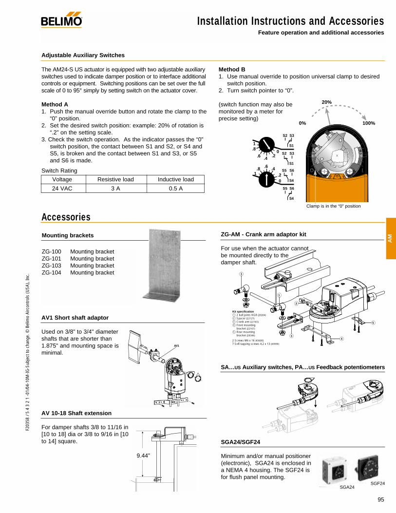
Adjustable Auxiliary Switches
The AM24-S US actuator is equipped with two adjustable auxiliaryswitches used to indicate damper position or to interface additionalcontrols or equipment. Switching positions can be set over the fullscale of 0 to 95° simply by setting switch on the actuator cover.
Method A1. Push the manual override button and rotate the clamp to the
“0” position.2. Set the desired switch position: example: 20% of rotation is
“.2” on the setting scale.3. Check the switch operation. As the indicator passes the “0”
switch position, the contact between S1 and S2, or S4 andS5, is broken and the contact between S1 and S3, or S5and S6 is made.
Method B1. Use manual override to position universal clamp to desired
switch position.2. Turn switch pointer to “0”.
(switch function may also be monitored by a meter for precise setting)
0% 100%
20%
1
0.2
.4.6.8
S4
S6S5
S4
S6S5
1
0.2.4.6
.8
S1
S3S2
S1
S3S2
Voltage Resistive load Inductive load
24 VAC 3 A 0.5 A
Switch Rating
Clamp is in the “0” position
Accessories
®
ZG-AM - Crank arm adaptor kit
For use when the actuator cannot be mounted directly to the damper shaft.

96
F203
58 /
5 4
3 2
1 -0
1/04
-10M
-IG-S
ubje
ct to
cha
nge.
© B
elim
o Ai
rcon
trols
(USA
), In
c.
Startup and Checkout ®
Procedure
Control signal is applied to actuator.
Check power wiring. Correct anyproblems. See Note 1.
Turn reversing switch to the correctposition.
Push manual override button. (Ifclamp is at min signal position, movedamper to fully closed position)
Make sure the control signal positive(+) is connected to Wire No 3 andcontrol signal negative (-) is connect-ed to wire No. 1. Most control prob-lems are caused by reversing thesetwo wires. Verify that the reversingswitch is all the way CCW or CW.
Check input signal with a digital voltmeter (DVM). Make sure the input iswithin the range of the actuator. ForAM24SR US this is 0 to 10 VDC or0 to 20 mA. Note: The input signal must be abovethe 2 VDC or 4 mA to have the actu-ator move.
Use the manual override button tomove the damper by hand from fullyclosed to fully open.
Check damper torque requirement.
Actuator works properly. Test con-troller by following controller manu-facturer's instructions.
Expected Response
Actuator will move to its “ControlSignal” position.
Power supply rating should be ≥the total power requirement ofthe actuator(s). Minimum volt-age of 19.2 VAC or 21.6 VDC.
Actuator will move to its “ControlSignal” position.
Actuator will drive to 0 positionand back to control position
Drives to “Control Signal” posi-tion
Input voltage or current shouldbe ±1% of what controller'sadjustment or programming indi-cate.
Damper will go from fully closedto fully open.
Torque requirement is ≤ actua-tor’s minimum torque.
Gives ExpectedResponse
Go To Step…
Actuator operatesproperlyStep 9
Power wiring correct-ed, actuator begins
to driveStep 1
Actuator operatesproperly.Step 9
Actuator operatesproperly.Step 9
Actuator operatesproperly.Step 9
Controller output(actuator input) is
correct. InputPolarity Correct.
Step 7
Damper moves properlyStep 8
Defective Actuator.Replace Actuator -
See Note 2
Does Not GiveExpected Response
Go To Step…
No response at allStep 2
Operation isreversedStep 3
Does not drivetoward "ControlSignal Position"
Step 4
Power wiringcorrected, actuatorstill does not drive
Step 4
Does not drivetoward “ControlSignal Position”
Step 4
Step 5
Step 6
Reprogram, adjustrepair or replace
controller as needed.Step 1
Find cause ofdamper jam and
repair.Step 1
Recalculate actuatorrequirement and
correct installation.
Step
1.
2.
3.
4.
5.
6.
7.
8.
9.
Note 1 Check that the transformer(s) are sized properly. • If a common transformer is used, make sure that polarity is observed on the secondary. This means connect all No. 1 wires to one leg of
the transformer and all No. 2 wires to the other leg of the transformer. • If multiple transformers are used with one control signal, make sure all No. 1 wires are tied together and tied to control signal negative (-).• Controllers and actuators must have separate 24 VAC/VDC power sources.
Note 2 If failure occurs within 5 years from original installation date, notify Belimo and give details of the application.
AM24SR US Electrical check-out procedure