aluminum spot welding general considerations. resistance welding lesson objectives when you finish...
TRANSCRIPT
Aluminum Spot Welding
General Considerations
Resistance Welding
Lesson ObjectivesWhen you finish this lesson you will understand:•
Learning Activities1. View Slides; 2. Read Notes, 3. Listen to lecture4. Do on-line workbook
Keywords
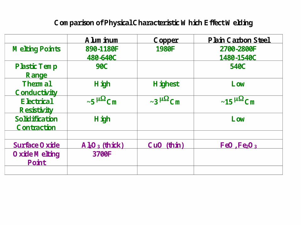
Comparison of Physical Characteristic Which Effect Welding
Aluminum Copper Plain Carbon SteelMelting Points 890-1180F
480-640C1980F 2700-2800F
1480-1540CPlastic Temp
Range90C 540C
ThermalConductivity
High Highest Low
ElectricalResistivity
~5 Cm ~3 Cm ~15 Cm
SolidificationContraction
High Low
Surface Oxide Al2O3 (thick) CuO (thin) FeO, Fe2O3
Oxide MeltingPoint
3700F
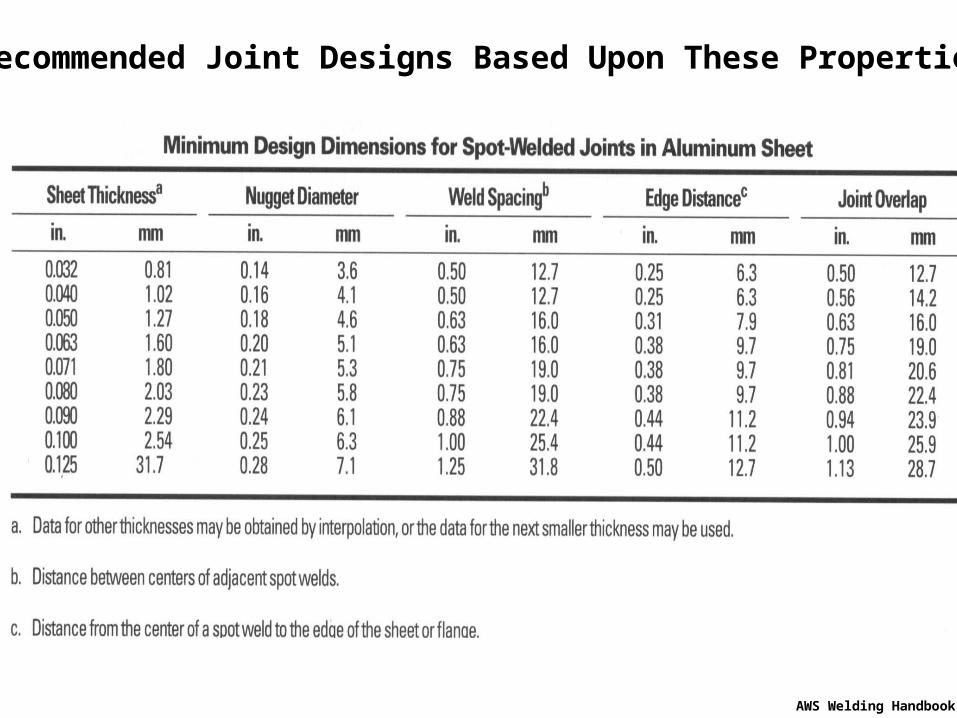
Recommended Joint Designs Based Upon These Properties
AWS Welding Handbook
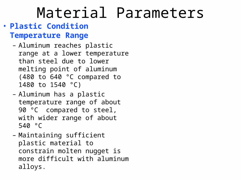
Material Parameters• Plastic Condition
Temperature Range– Aluminum reaches plastic range
at a lower temperature than steel due to lower melting point of aluminum (480 to 640 °C compared to 1480 to 1540 °C)
– Aluminum has a plastic temperature range of about 90 °C compared to steel, with wider range of about 540 °C
– Maintaining sufficient plastic material to constrain molten nugget is more difficult with aluminum alloys.
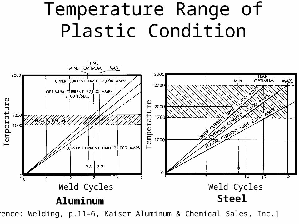
Temperature Range of Plastic Condition
Weld Cycles Weld Cycles
Tem
pera
ture
Tem
pera
ture
[Reference: Welding, p.11-6, Kaiser Aluminum & Chemical Sales, Inc.]
Aluminum Steel
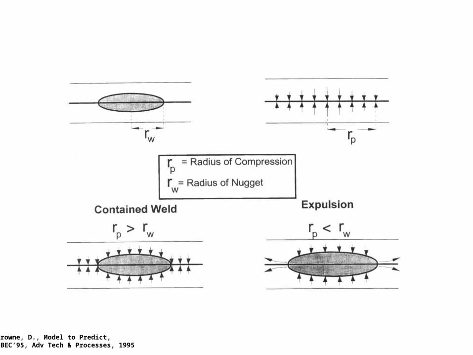
Browne, D., Model to Predict,IBEC’95, Adv Tech & Processes, 1995
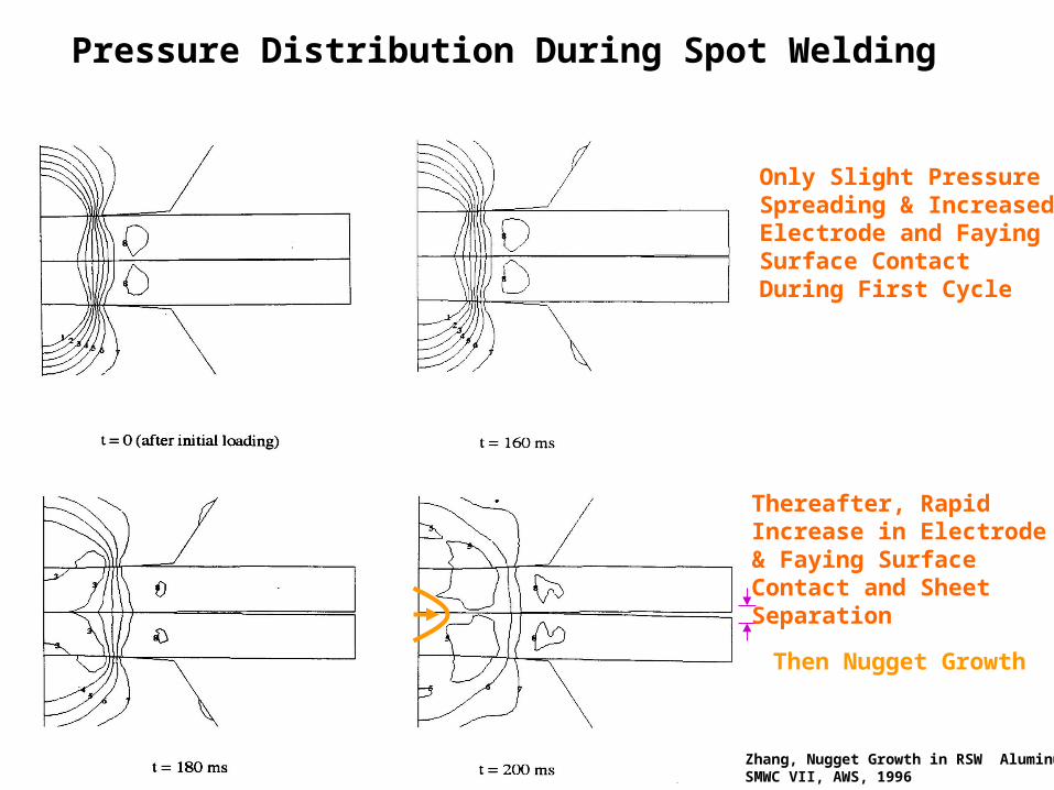
Pressure Distribution During Spot Welding
Only Slight Pressure Spreading & IncreasedElectrode and FayingSurface Contact During First Cycle
Thereafter, RapidIncrease in Electrode& Faying SurfaceContact and SheetSeparation
Then Nugget Growth
Zhang, Nugget Growth in RSW AluminumSMWC VII, AWS, 1996
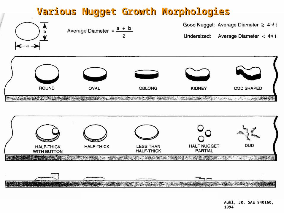
Auhl, JR, SAE 940160,1994
Various Nugget Growth MorphologiesVarious Nugget Growth Morphologies
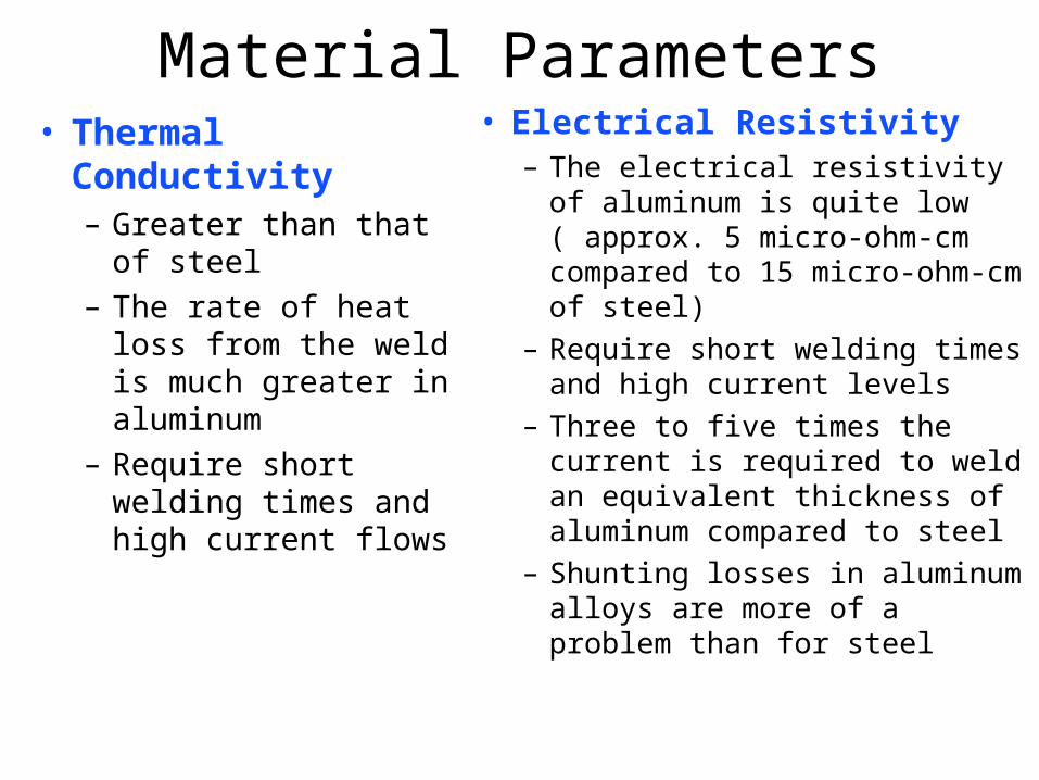
• Thermal Conductivity– Greater than that of
steel
– The rate of heat loss from the weld is much greater in aluminum
– Require short welding times and high current flows
Material Parameters• Electrical Resistivity
– The electrical resistivity of aluminum is quite low ( approx. 5 micro-ohm-cm compared to 15 micro-ohm-cm of steel)
– Require short welding times and high current levels
– Three to five times the current is required to weld an equivalent thickness of aluminum compared to steel
– Shunting losses in aluminum alloys are more of a problem than for steel
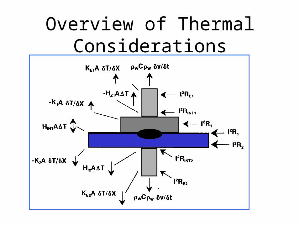
Overview of Thermal Considerations
Case Studies of Common Electrode Heat Flow Conditions
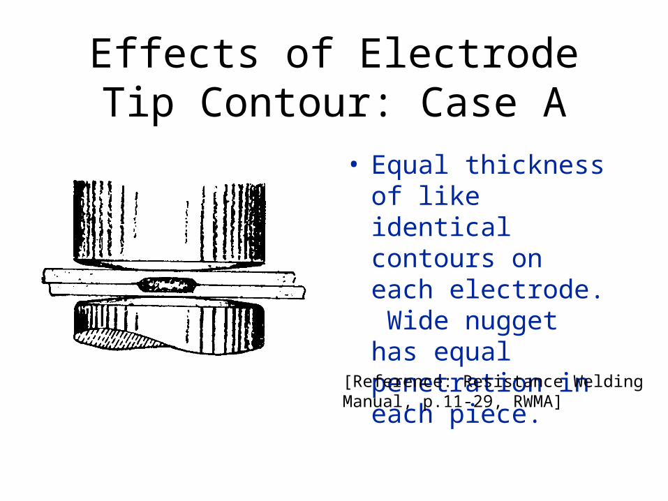
Effects of Electrode Tip Contour: Case A
• Equal thickness of like identical contours on each electrode. Wide nugget has equal penetration in each piece.
[Reference: Resistance WeldingManual, p.11-29, RWMA]
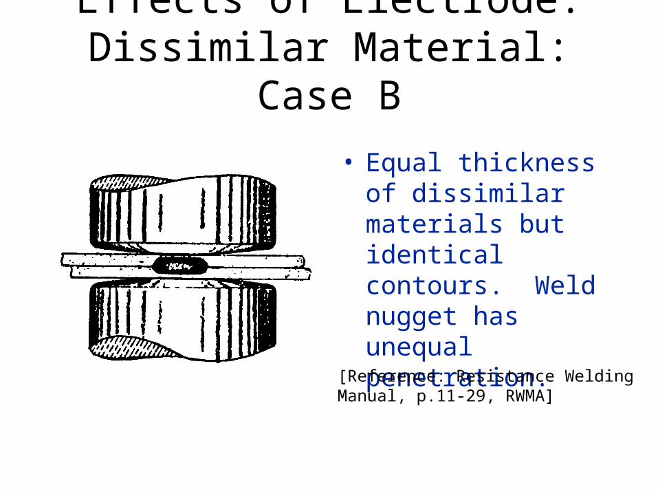
Effects of Electrode: Dissimilar Material: Case B
• Equal thickness of dissimilar materials but identical contours. Weld nugget has unequal penetration.
[Reference: Resistance WeldingManual, p.11-29, RWMA]
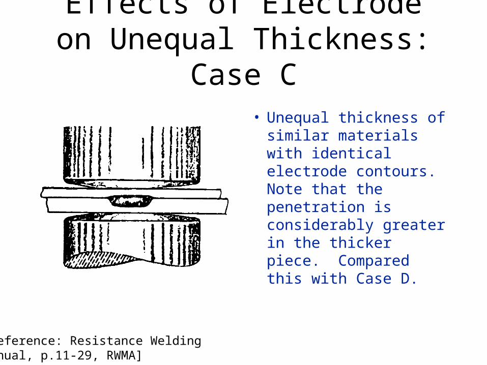
Effects of Electrode on Unequal Thickness: Case C
• Unequal thickness of similar materials with identical electrode contours. Note that the penetration is considerably greater in the thicker piece. Compared this with Case D.
[Reference: Resistance WeldingManual, p.11-29, RWMA]
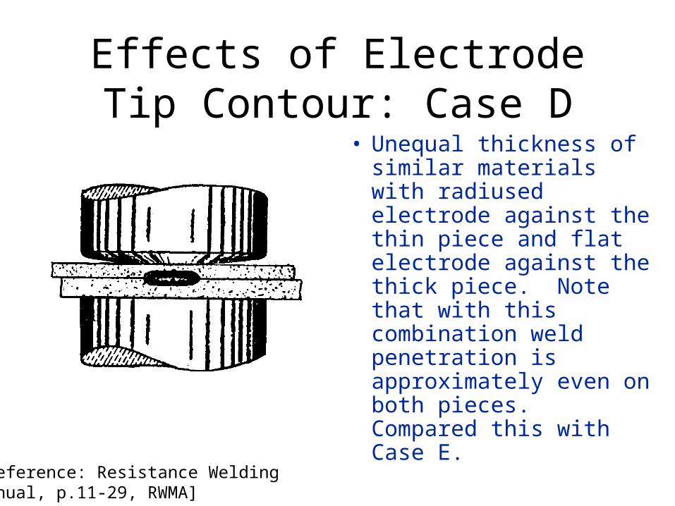
Effects of Electrode Tip Contour: Case D
• Unequal thickness of similar materials with radiused electrode against the thin piece and flat electrode against the thick piece. Note that with this combination weld penetration is approximately even on both pieces. Compared this with Case E.
[Reference: Resistance WeldingManual, p.11-29, RWMA]
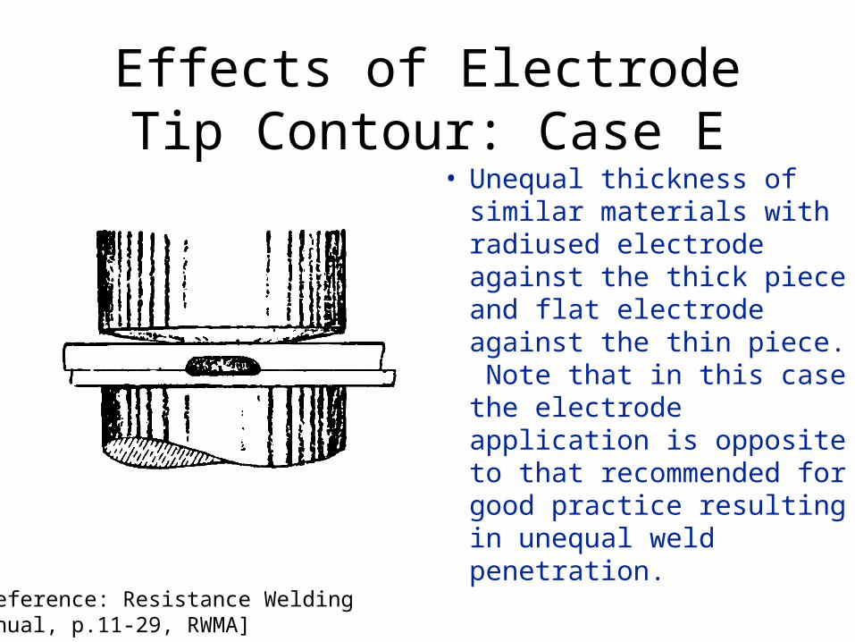
Effects of Electrode Tip Contour: Case E
• Unequal thickness of similar materials with radiused electrode against the thick piece and flat electrode against the thin piece. Note that in this case the electrode application is opposite to that recommended for good practice resulting in unequal weld penetration.
[Reference: Resistance WeldingManual, p.11-29, RWMA]
Material Parameters (CONT.)• Expansion and Contraction
– Undergo greater expansion and contraction during melting and solidification processes than does steel
– Dimensional changes are greatest in the weld zone and commonly result in nugget cracking
– Machines with Low Inertia Heads help electrodes “follow-up” nugget solidification
– Post weld forges are often used to prevent cracking
– Current Decay during the solidification process helps
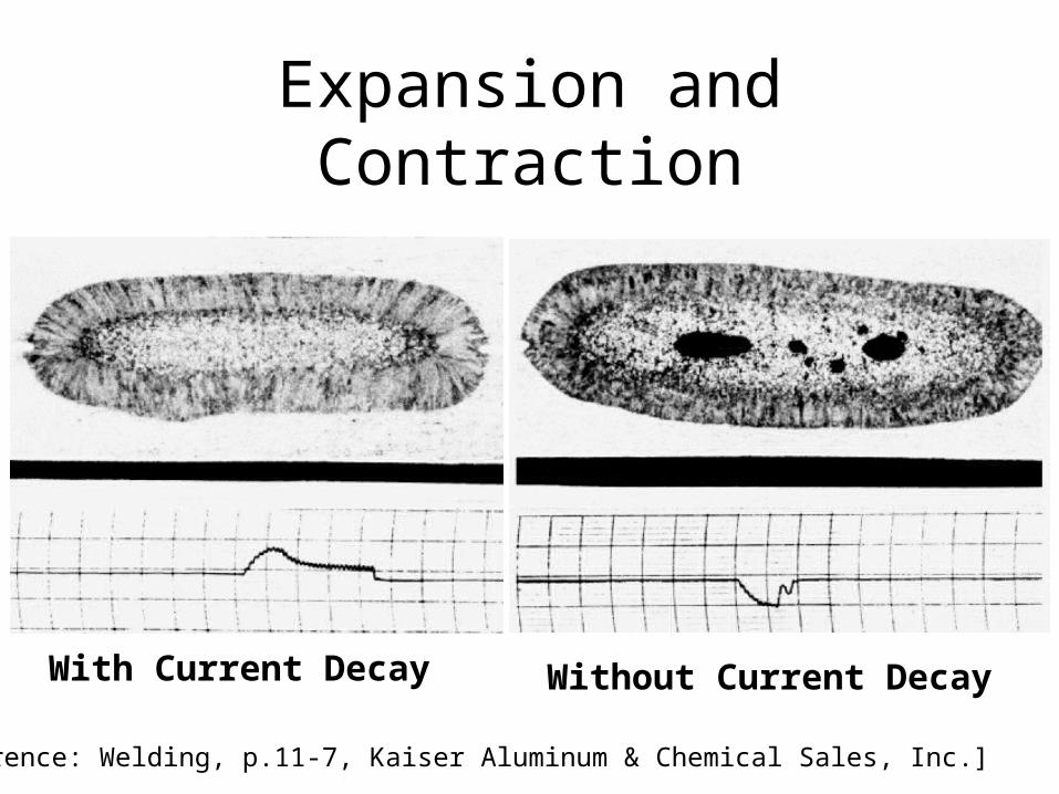
Expansion and Contraction
[Reference: Welding, p.11-7, Kaiser Aluminum & Chemical Sales, Inc.]
With Current Decay Without Current Decay
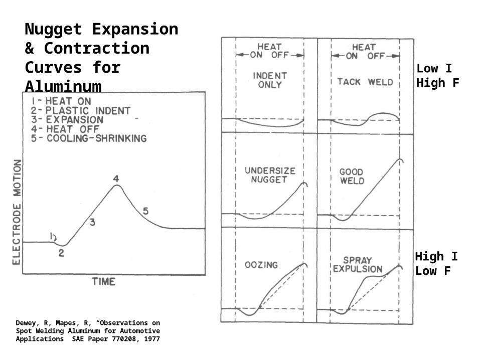
Low IHigh F
High ILow F
Dewey, R, Mapes, R, “Observations on Spot Welding Aluminum for Automotive Applications” SAE Paper 770208, 1977
Nugget Expansion & Contraction Curves for Aluminum
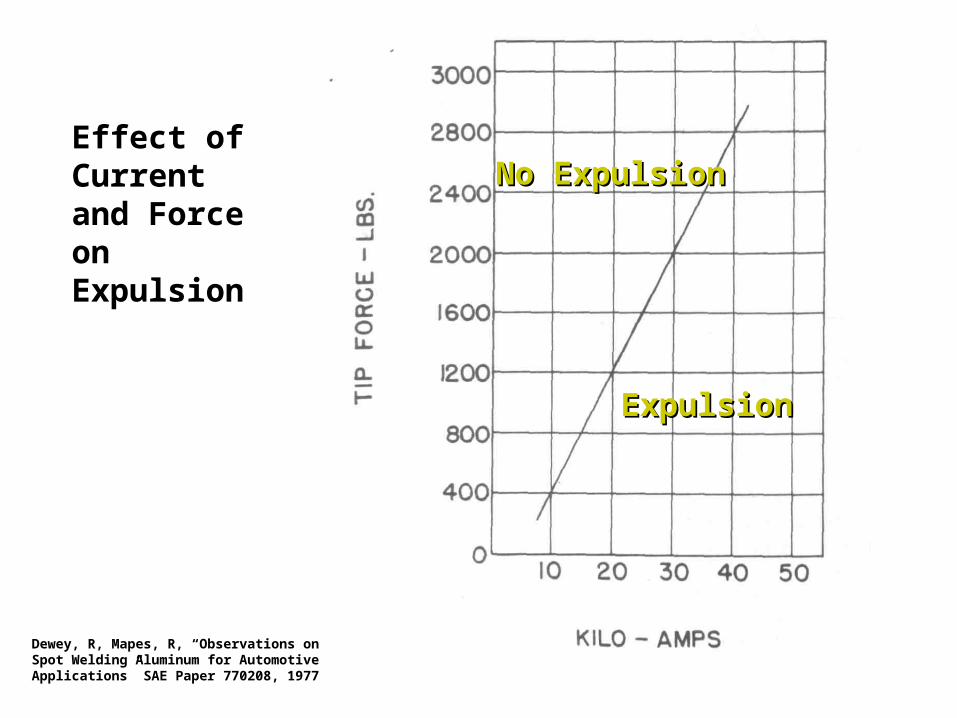
Dewey, R, Mapes, R, “Observations on Spot Welding Aluminum for Automotive Applications” SAE Paper 770208, 1977
ExpulsionExpulsion
No ExpulsionNo ExpulsionEffect of Current and Force on Expulsion
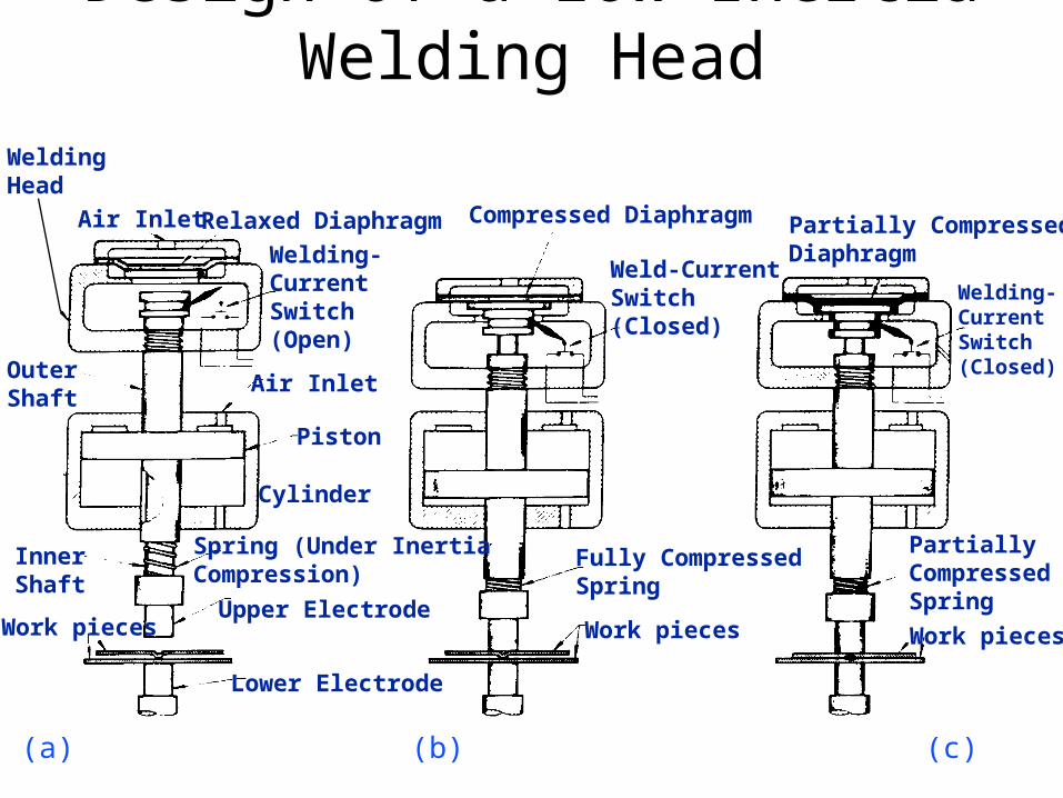
Design of a Low Inertia Welding Head
Air Inlet Relaxed Diaphragm
Welding-CurrentSwitch(Open)
Air Inlet
Piston
Cylinder
WeldingHead
OuterShaft
InnerShaft
Work pieces
Spring (Under InertiaCompression)
Upper Electrode
Lower Electrode
Compressed Diaphragm
Weld-CurrentSwitch(Closed)
Fully CompressedSpring
Work pieces
Partially CompressedDiaphragm
Welding-CurrentSwitch(Closed)
PartiallyCompressedSpring
Work pieces
(a) (b) (c)
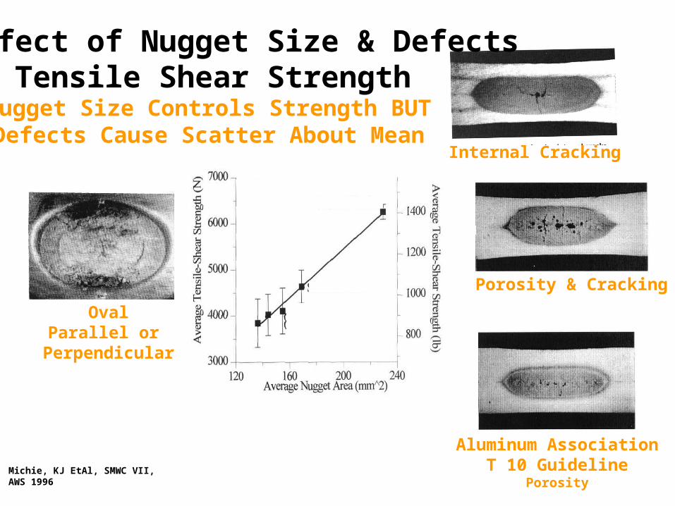
Effect of Nugget Size & DefectsOn Tensile Shear Strength
OvalParallel or
Perpendicular
Aluminum AssociationT 10 Guideline
Porosity
Porosity & Cracking
Internal Cracking
Michie, KJ EtAl, SMWC VII, AWS 1996
Nugget Size Controls Strength BUTDefects Cause Scatter About Mean

Auhl, JR, SAE 940160,1994
Effect of Defects at a Constant Nugget Size
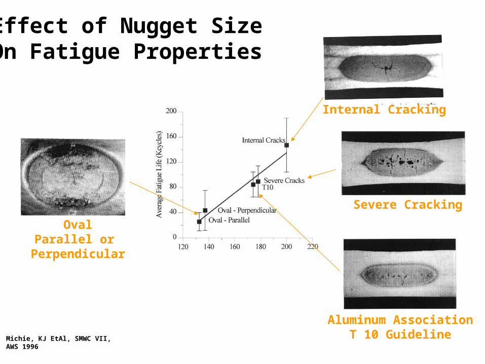
Michie, KJ EtAl, SMWC VII, AWS 1996
OvalParallel or
Perpendicular
Internal Cracking
Severe Cracking
Aluminum AssociationT 10 Guideline
Effect of Nugget SizeOn Fatigue Properties
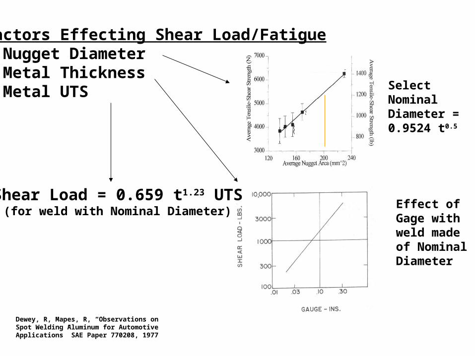
Factors Effecting Shear Load/Fatigue• Nugget Diameter• Metal Thickness• Metal UTS Select Nominal
Diameter = 0.9524 t0.5
Effect of Gage with weld made of Nominal Diameter
Shear Load = 0.659 t1.23 UTS(for weld with Nominal Diameter)
Dewey, R, Mapes, R, “Observations on Spot Welding Aluminum for Automotive Applications” SAE Paper 770208, 1977
Surface-Related Problems• Surface-Condition Issues
– Revolve around the aluminum oxide film which forms on the surface of the aluminum
– As this oxide grows, the effective contact resistance of the aluminum changes
– As the electrode comes in contact with the sheet surface, this oxide fractures non-uniformly and creates only small areas for the passage of current
– Results in Electrode Life deterioration
• Oxide Removal Methods– Chemical removal
– Abrasive removal
– Stabilization after oxide removal
– Arc cleaning the surface immediately before welding
– Conversion coatings
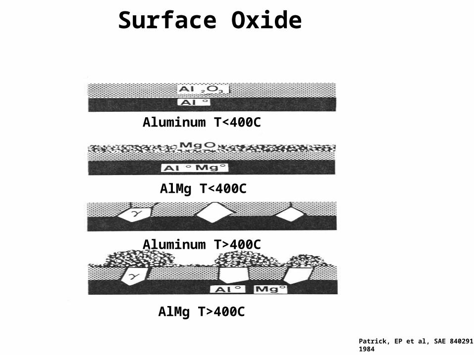
Surface Oxide
Aluminum T<400C
AlMg T<400C
Aluminum T>400C
AlMg T>400C
Patrick, EP et al, SAE 840291,1984
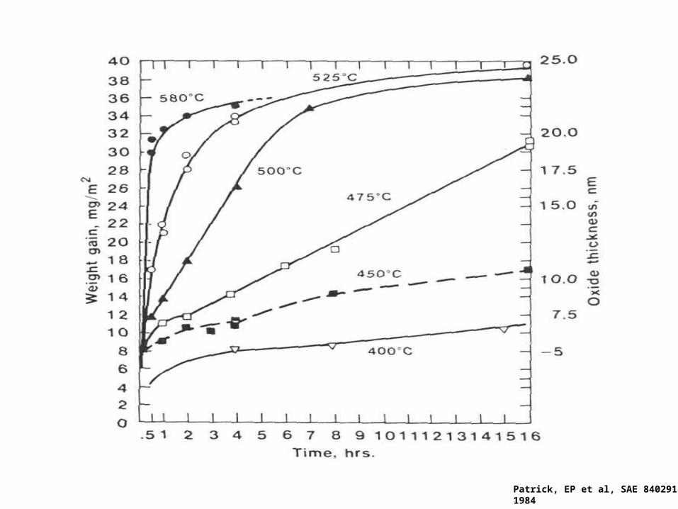
Patrick, EP et al, SAE 840291,1984
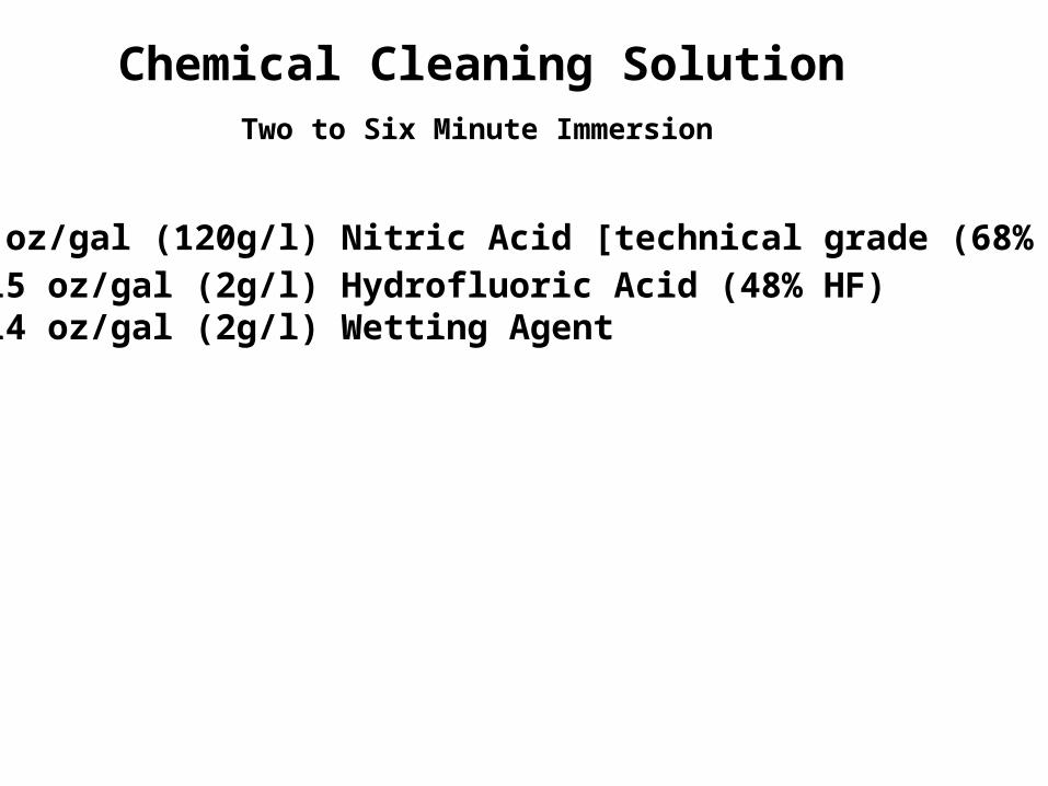
Chemical Cleaning SolutionTwo to Six Minute Immersion
• 15 oz/gal (120g/l) Nitric Acid [technical grade (68% HNO3
• 0.15 oz/gal (2g/l) Hydrofluoric Acid (48% HF)• 0.14 oz/gal (2g/l) Wetting Agent
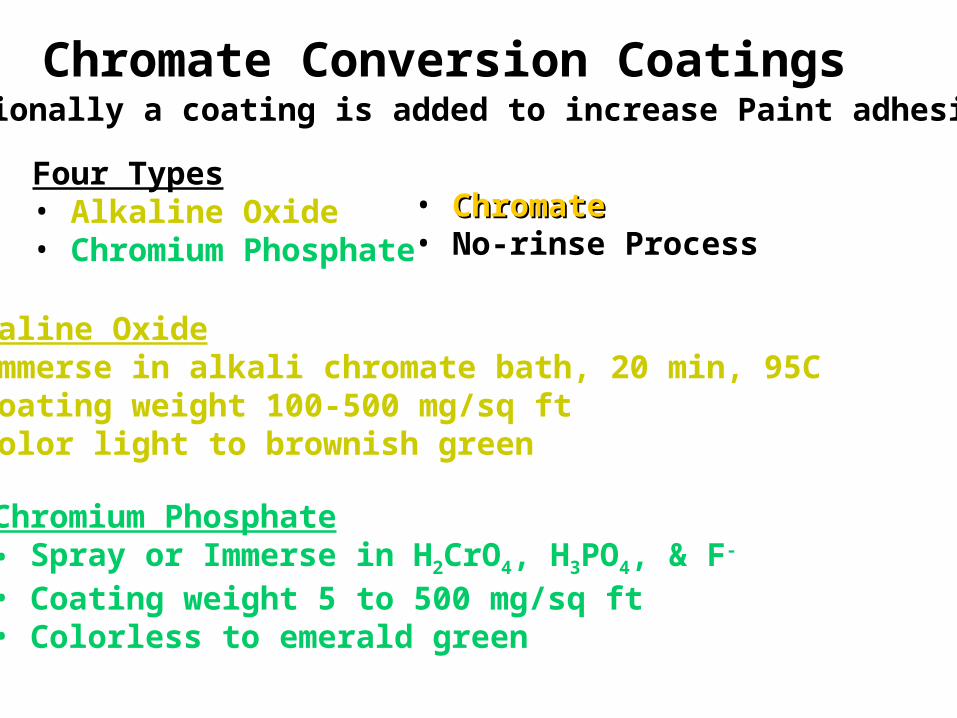
Chromate Conversion CoatingsOccasionally a coating is added to increase Paint adhesion
Four Types• Alkaline Oxide• Chromium Phosphate
• ChromateChromate• No-rinse Process
Alkaline Oxide• Immerse in alkali chromate bath, 20 min, 95C• Coating weight 100-500 mg/sq ft• Color light to brownish green
Chromium Phosphate• Spray or Immerse in H2CrO4, H3PO4, & F-
• Coating weight 5 to 500 mg/sq ft• Colorless to emerald green
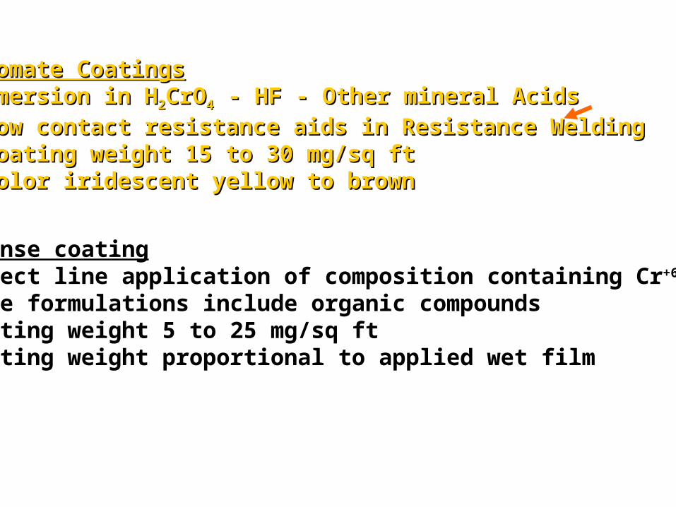
Chromate CoatingsChromate Coatings• Emersion in HEmersion in H22CrOCrO44 - HF - Other mineral Acids - HF - Other mineral Acids• Low contact resistance aids in Resistance WeldingLow contact resistance aids in Resistance Welding• Coating weight 15 to 30 mg/sq ftCoating weight 15 to 30 mg/sq ft• Color iridescent yellow to brownColor iridescent yellow to brown
No-rinse coating• Direct line application of composition containing Cr+6 & Cr+3
• Some formulations include organic compounds• Coating weight 5 to 25 mg/sq ft• Coating weight proportional to applied wet film
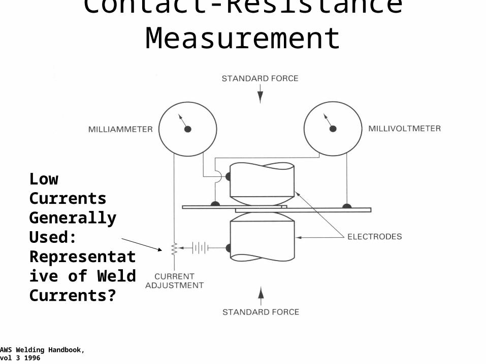
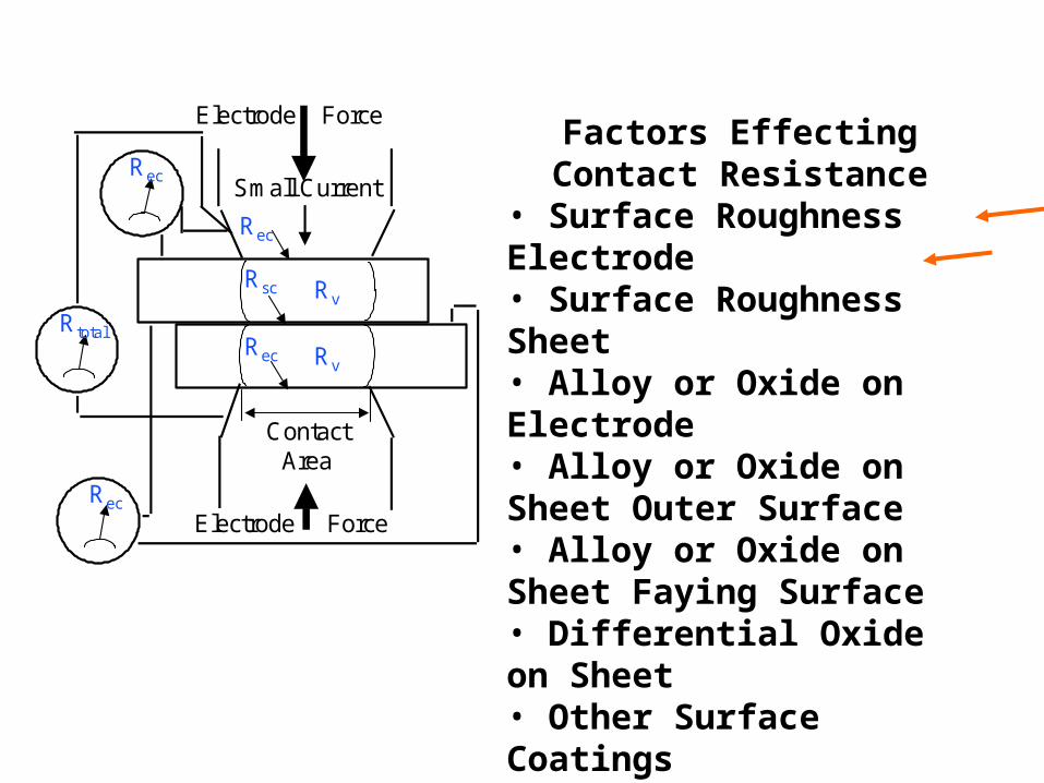
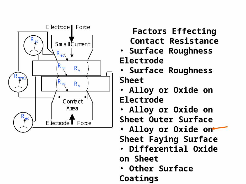
Contact-Resistance Measurement
AWS Welding Handbook,vol 3 1996
Low Currents Generally Used: Representative of Weld Currents?
ContactArea
Electrode Force
Electrode Force
Small Current
Rec
Rec
Rsc
Rv
Rv
Rec
Rec
Rtotal
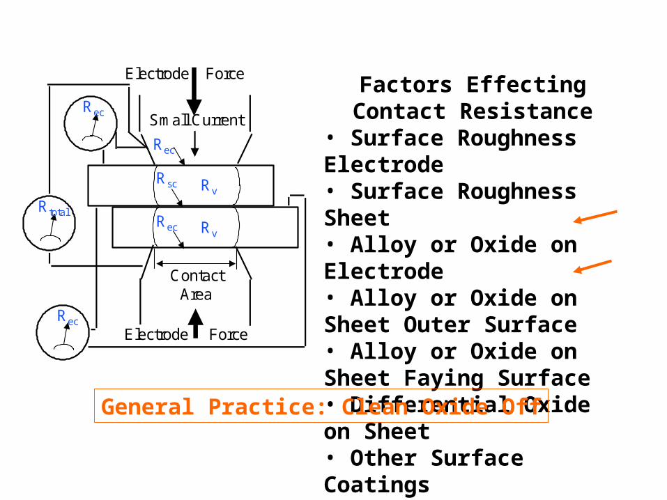
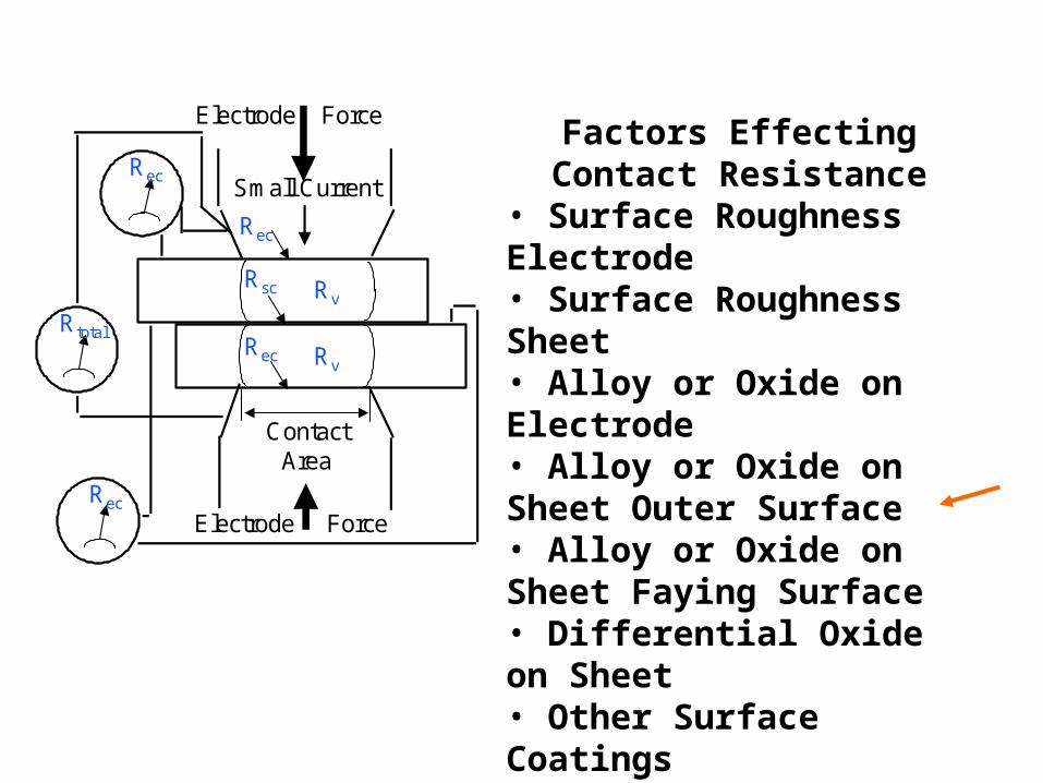
Factors Effecting Contact Resistance
• Surface Roughness Electrode• Surface Roughness Sheet• Alloy or Oxide on Electrode• Alloy or Oxide on Sheet Outer Surface• Alloy or Oxide on Sheet Faying Surface• Differential Oxide on Sheet• Other Surface Coatings
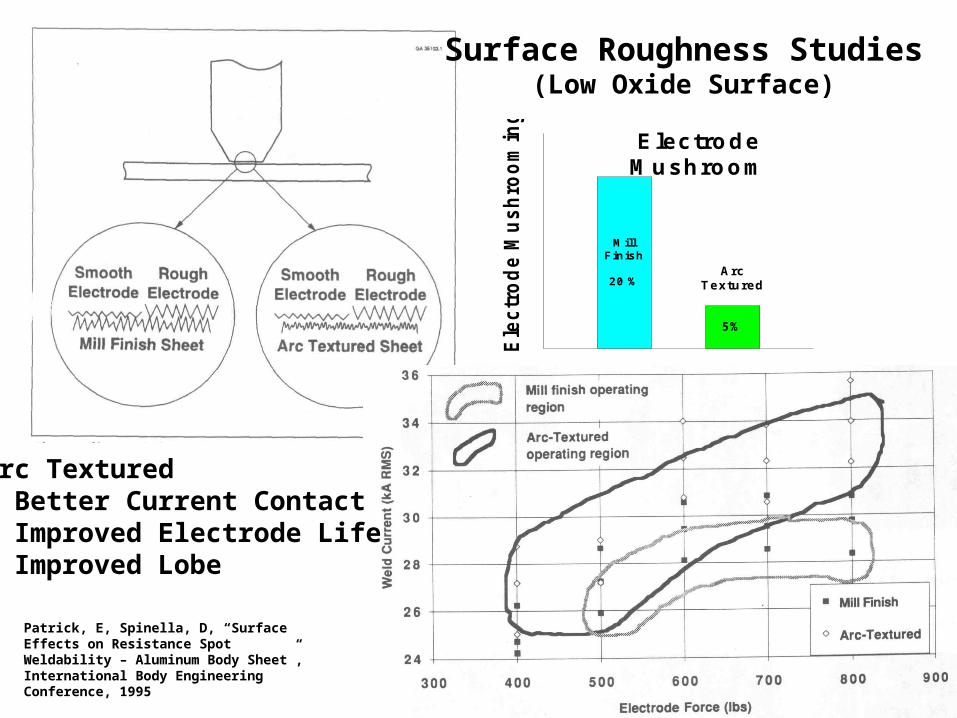
Patrick, E, Spinella, D, “Surface Effects on Resistance Spot Weldability – Aluminum Body Sheet”, International Body Engineering Conference, 1995
Surface Roughness Studies(Low Oxide Surface)
MillFinish
20 %
5%
Ele
ctr
od
e M
ush
roo
min
g (
%)
ArcTextured
ElectrodeM ushroom
Arc Textured • Better Current Contact• Improved Electrode Life• Improved Lobe
ContactArea
Electrode Force
Electrode Force
Small Current
Rec
Rec
Rsc
Rv
Rv
Rec
Rec
Rtotal
Factors Effecting Contact Resistance
• Surface Roughness Electrode• Surface Roughness Sheet• Alloy or Oxide on Electrode• Alloy or Oxide on Sheet Outer Surface• Alloy or Oxide on Sheet Faying Surface• Differential Oxide on Sheet• Other Surface Coatings
General Practice: Clean Oxide Off
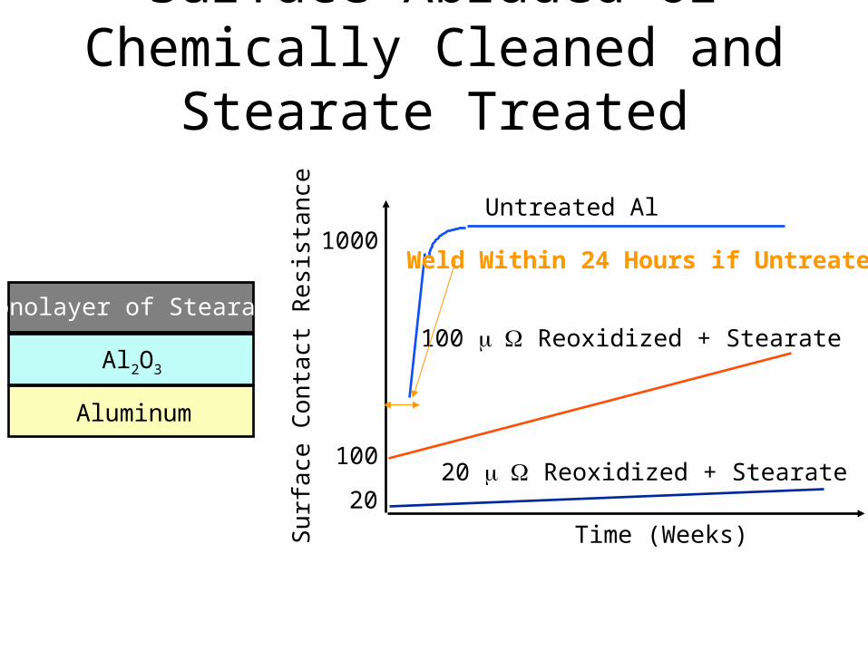
Surface Abraded or Chemically Cleaned and Stearate Treated
1000
100
20Su
rfa
ce C
on
tact
Res
ista
nce
Untreated Al
100 Reoxidized + Stearate
20 Reoxidized + Stearate
Time (Weeks)
Aluminum
Al2O3
Monolayer of Stearate
Weld Within 24 Hours if Untreated
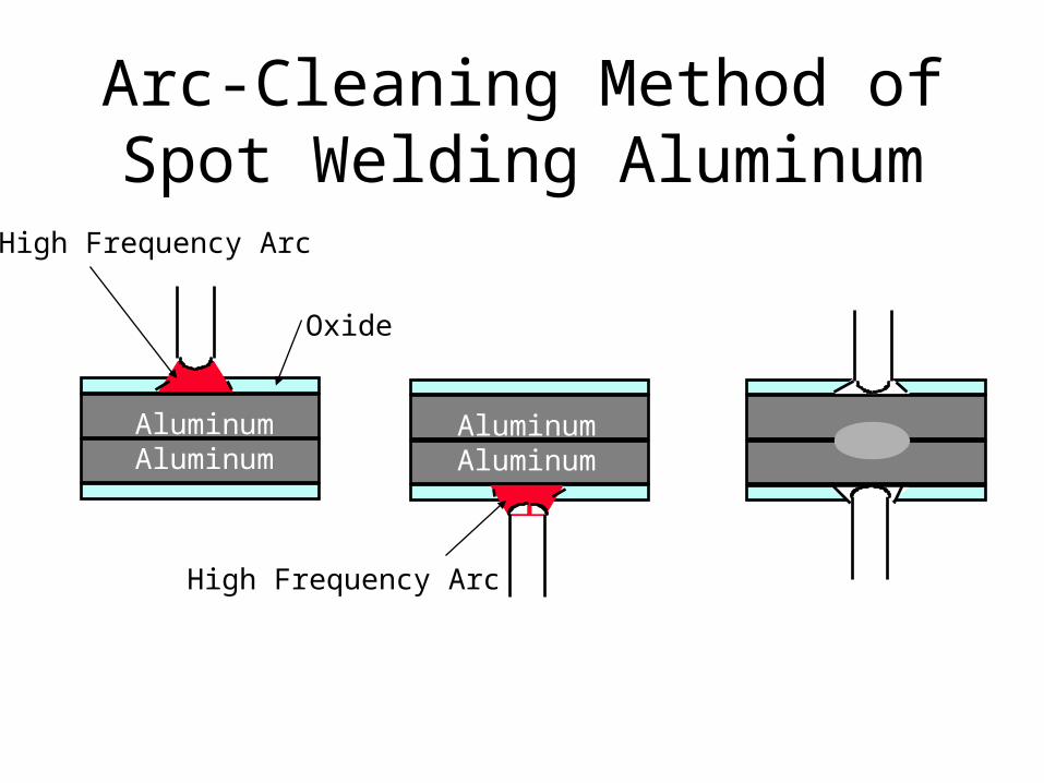
Arc-Cleaning Method of Spot Welding Aluminum
Oxide
AluminumAluminum
AluminumAluminum
High Frequency Arc
High Frequency Arc
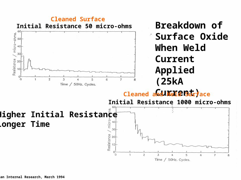
Initial Resistance 50 micro-ohms
Initial Resistance 1000 micro-ohms
Breakdown of Surface Oxide When Weld Current Applied(25kA Current)
Higher Initial ResistanceLonger Time
Alcan Internal Research, March 1994
Cleaned Surface
Cleaned and Held Surface
Initial Resistance 50 micro-ohms Initial Resistance 1000 micro-ohms
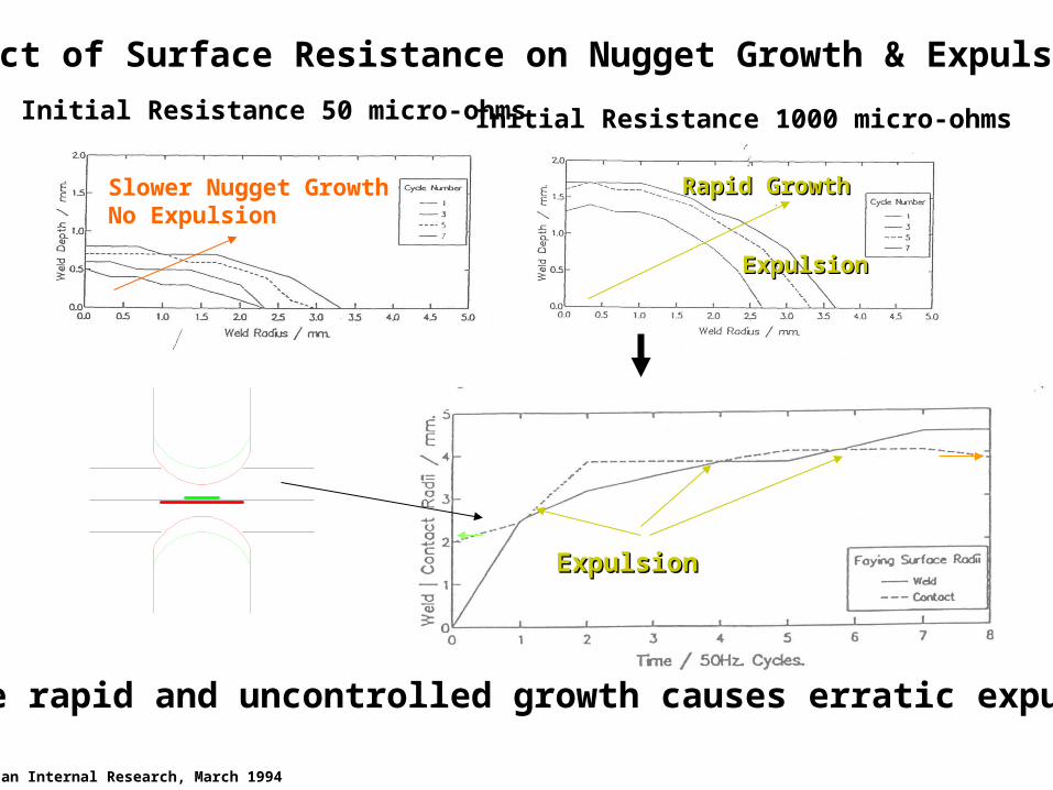
Effect of Surface Resistance on Nugget Growth & Expulsion
ExpulsionExpulsion
The more rapid and uncontrolled growth causes erratic expulsion
Alcan Internal Research, March 1994
Slower Nugget GrowthNo Expulsion
Rapid GrowthRapid Growth
ExpulsionExpulsion
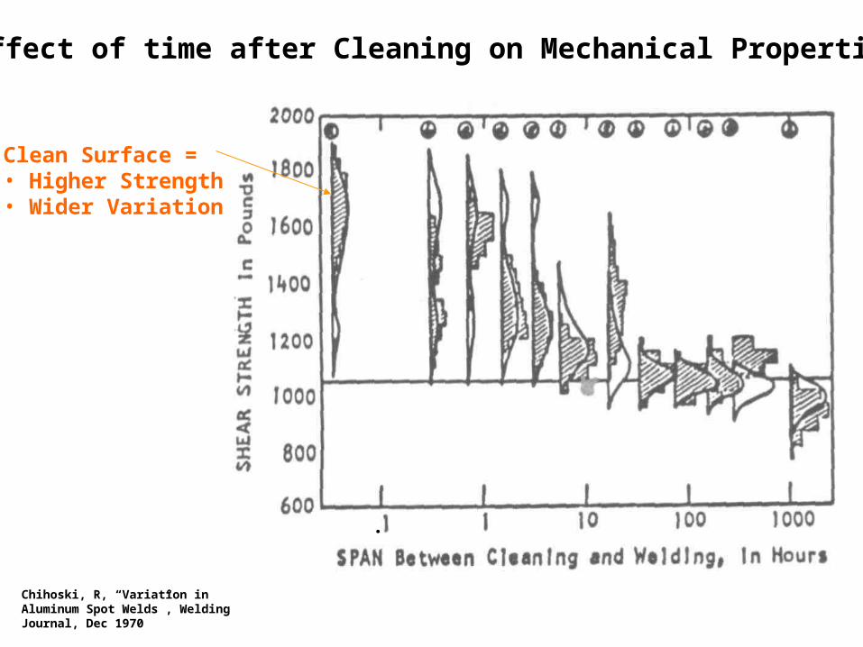
Effect of time after Cleaning on Mechanical Properties
Clean Surface =• Higher Strength• Wider Variation
Chihoski, R, “Variation in Aluminum Spot Welds”, Welding Journal, Dec 1970
.
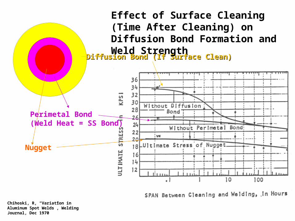
Nugget
Perimetal Bond(Weld Heat = SS Bond)
Diffusion Bond (If Surface Clean)Diffusion Bond (If Surface Clean)
Effect of Surface Cleaning (Time After Cleaning) on Diffusion Bond Formation and Weld Strength
Chihoski, R, “Variation in Aluminum Spot Welds”, Welding Journal, Dec 1970
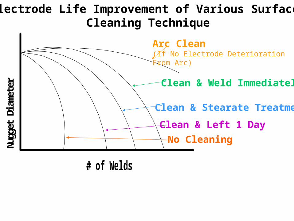
# of Welds
Nugg
et D
iamet
er
Arc Clean(If No Electrode DeteriorationFrom Arc)
Clean & Weld Immediately
Clean & Stearate Treatment
Clean & Left 1 Day
No Cleaning
Electrode Life Improvement of Various Surface Cleaning Technique
ContactArea
Electrode Force
Electrode Force
Small Current
Rec
Rec
Rsc
Rv
Rv
Rec
Rec
Rtotal
Factors Effecting Contact Resistance
• Surface Roughness Electrode• Surface Roughness Sheet• Alloy or Oxide on Electrode• Alloy or Oxide on Sheet Outer Surface• Alloy or Oxide on Sheet Faying Surface• Differential Oxide on Sheet• Other Surface Coatings
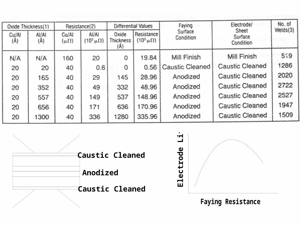
Anodized
Caustic Cleaned
Caustic Cleaned
Faying Resistance
Ele
ctr
od
e L
ife
ContactArea
Electrode Force
Electrode Force
Small Current
Rec
Rec
Rsc
Rv
Rv
Rec
Rec
Rtotal
Factors Effecting Contact Resistance
• Surface Roughness Electrode• Surface Roughness Sheet• Alloy or Oxide on Electrode• Alloy or Oxide on Sheet Outer Surface• Alloy or Oxide on Sheet Faying Surface• Differential Oxide on Sheet• Other Surface Coatings
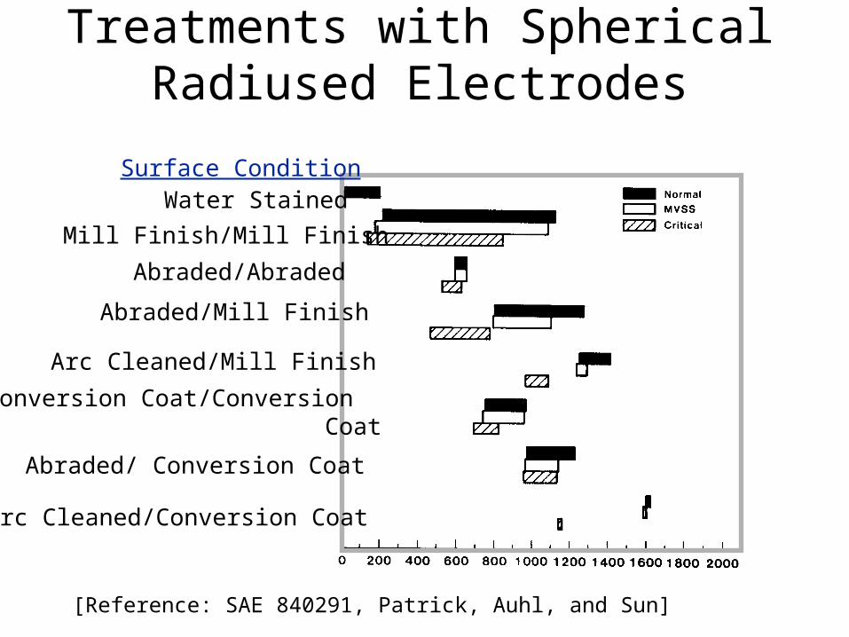
Screening Tests of Various Treatments with Spherical Radiused Electrodes
Surface ConditionWater Stained
Mill Finish/Mill Finish
Abraded/Abraded
Abraded/Mill Finish
Arc Cleaned/Mill Finish
Conversion Coat/Conversion Coat
Abraded/ Conversion Coat
Arc Cleaned/Conversion Coat
[Reference: SAE 840291, Patrick, Auhl, and Sun]

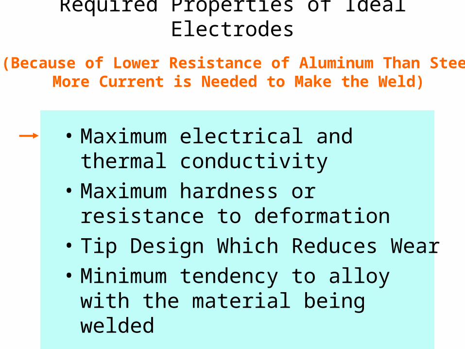
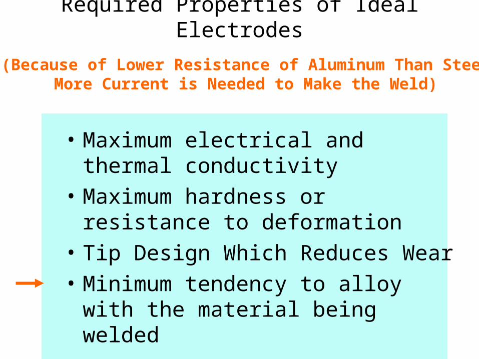
Required Properties of Ideal Electrodes
• Maximum electrical and thermal conductivity
• Maximum hardness or resistance to deformation
• Tip Design Which Reduces Wear
• Minimum tendency to alloy with the material being welded
(Because of Lower Resistance of Aluminum Than SteelMore Current is Needed to Make the Weld)
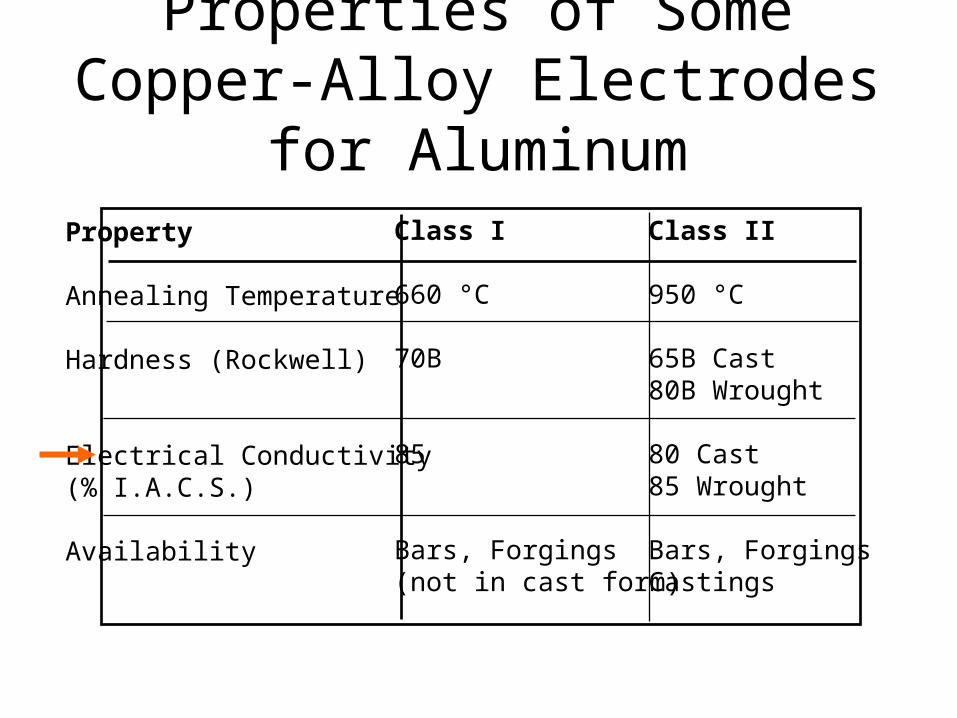
Properties of Some Copper-Alloy Electrodes for Aluminum
Property
Annealing Temperature
Hardness (Rockwell)
Electrical Conductivity(% I.A.C.S.)
Availability
Class I
660 °C
70B
85
Bars, Forgings(not in cast form)
Class II
950 °C
65B Cast80B Wrought
80 Cast85 Wrought
Bars, ForgingsCastings
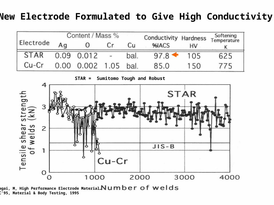
New Electrode Formulated to Give High Conductivity
STAR = Sumitomo Tough and Robust
Kumagai, M, High Performance Electrode Material…IBEC’95, Material & Body Testing, 1995
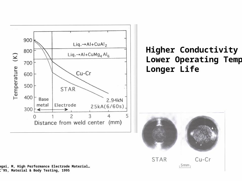
Higher Conductivity Lower Operating TempLonger Life
Kumagai, M, High Performance Electrode Material…IBEC’95, Material & Body Testing, 1995
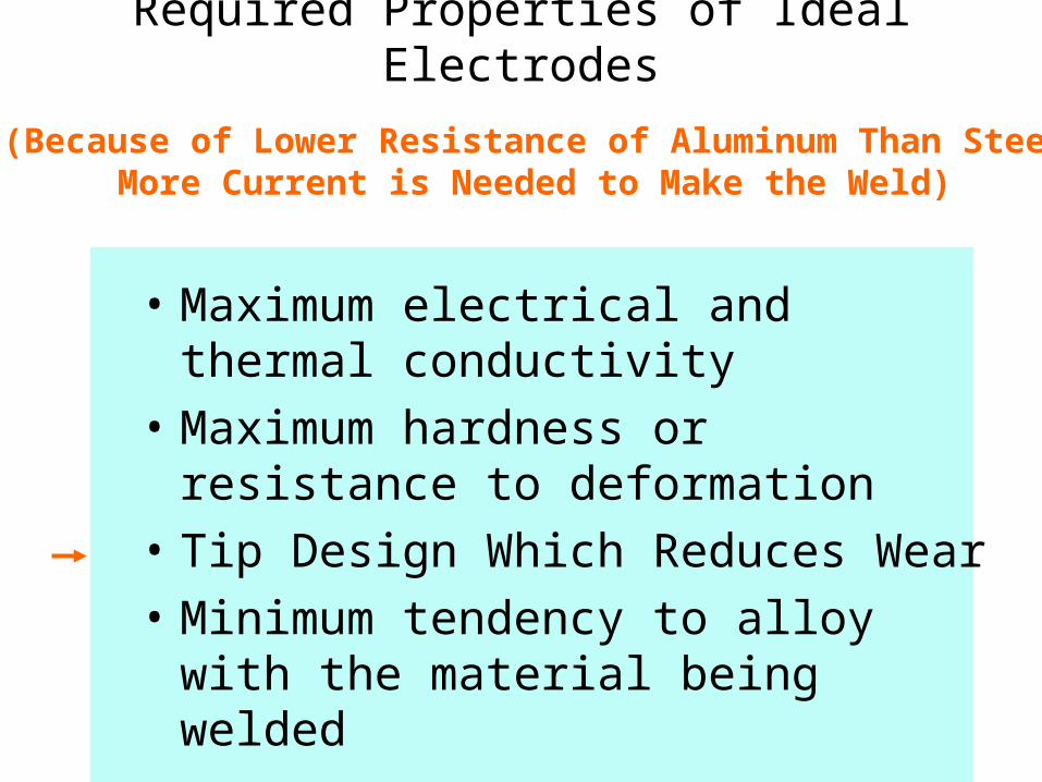
Required Properties of Ideal Electrodes
• Maximum electrical and thermal conductivity
• Maximum hardness or resistance to deformation
• Tip Design Which Reduces Wear
• Minimum tendency to alloy with the material being welded
(Because of Lower Resistance of Aluminum Than SteelMore Current is Needed to Make the Weld)
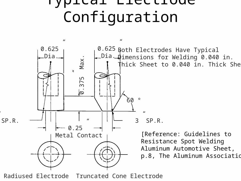
Typical Electrode Configuration
0.625”Dia.
0.625”Dia.
0.37
5” M
ax.
0.25” Metal Contact
3” SP.R. 3” SP.R.
Radiused Electrode Truncated Cone Electrode
60 °
Both Electrodes Have Typical Dimensions for Welding 0.040 in. Thick Sheet to 0.040 in. Thick Sheet
[Reference: Guidelines toResistance Spot WeldingAluminum Automotive Sheet,p.8, The Aluminum Association]
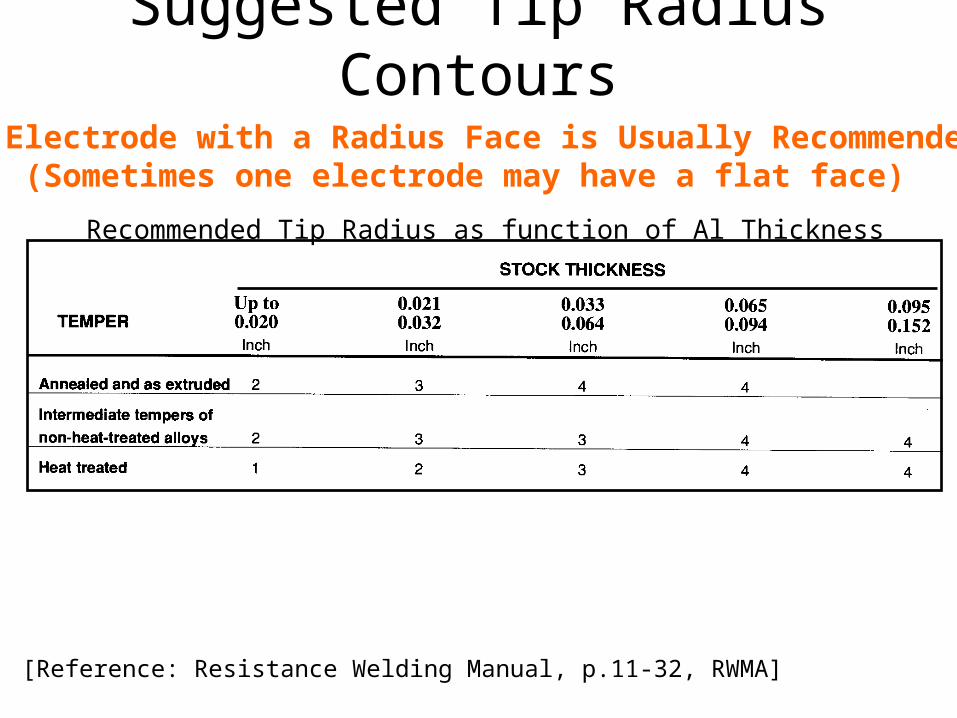
Suggested Tip Radius Contours
[Reference: Resistance Welding Manual, p.11-32, RWMA]
An Electrode with a Radius Face is Usually Recommended(Sometimes one electrode may have a flat face)
Recommended Tip Radius as function of Al Thickness
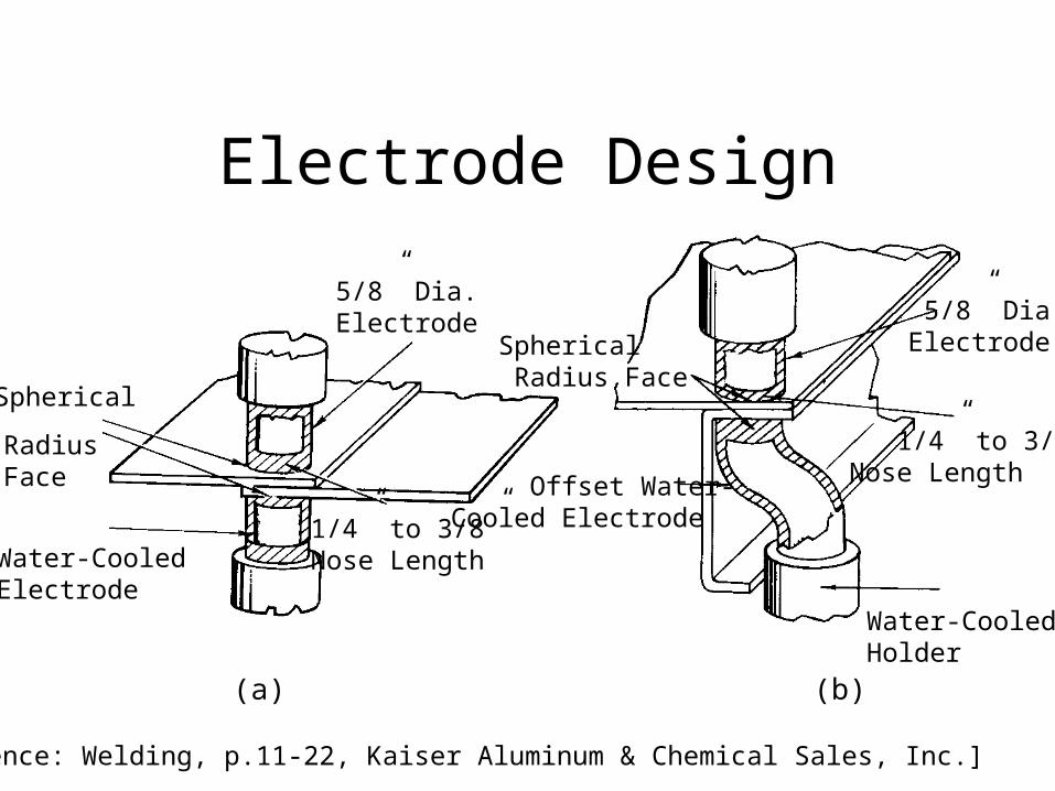
Electrode Design
5/8” Dia.Electrode
1/4” to 3/8”Nose Length
Spherical
RadiusFace
Water-CooledElectrode
Spherical Radius Face
Offset Water-Cooled Electrode
5/8” Dia.Electrode
1/4” to 3/8”Nose Length
Water-CooledHolder
(a) (b)
[Reference: Welding, p.11-22, Kaiser Aluminum & Chemical Sales, Inc.]
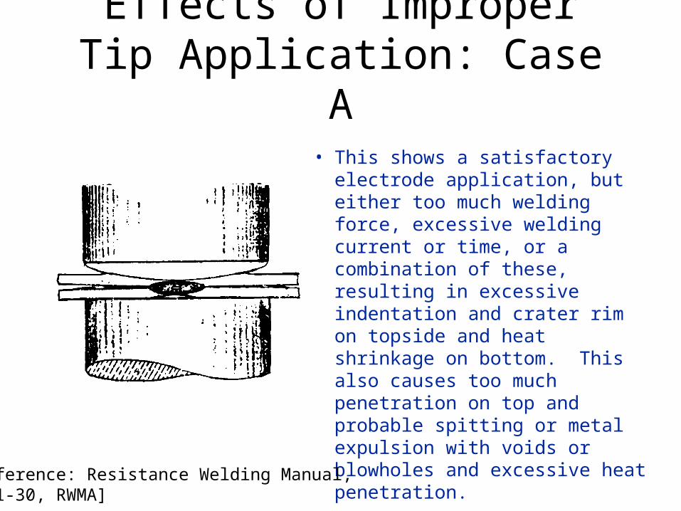
Effects of Improper Tip Application: Case A
• This shows a satisfactory electrode application, but either too much welding force, excessive welding current or time, or a combination of these, resulting in excessive indentation and crater rim on topside and heat shrinkage on bottom. This also causes too much penetration on top and probable spitting or metal expulsion with voids or blowholes and excessive heat penetration.
[Reference: Resistance Welding Manual, p.11-30, RWMA]
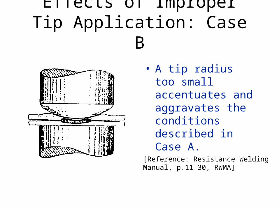
Effects of Improper Tip Application: Case B
• A tip radius too small accentuates and aggravates the conditions described in Case A.
[Reference: Resistance WeldingManual, p.11-30, RWMA]
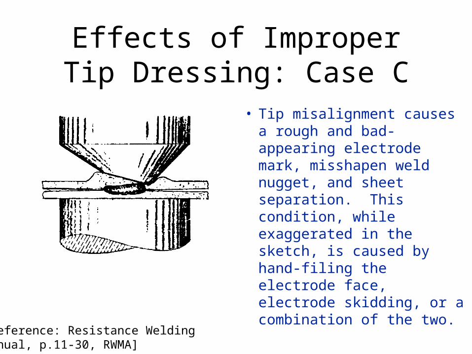
Effects of Improper Tip Dressing: Case C
• Tip misalignment causes a rough and bad-appearing electrode mark, misshapen weld nugget, and sheet separation. This condition, while exaggerated in the sketch, is caused by hand-filing the electrode face, electrode skidding, or a combination of the two.
[Reference: Resistance WeldingManual, p.11-30, RWMA]
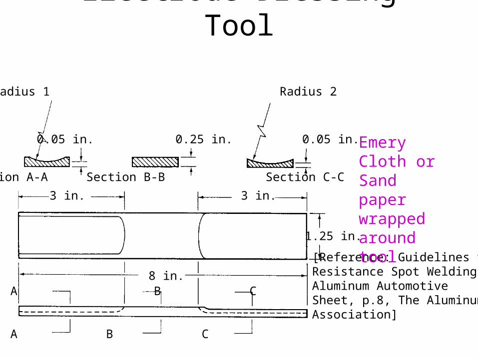
Electrode Dressing Tool
A B C
A B C
Section A-A Section B-B Section C-C
Radius 1 Radius 2
0.05 in. 0.25 in. 0.05 in.
3 in. 3 in.
8 in.
1.25 in.
[Reference: Guidelines toResistance Spot WeldingAluminum Automotive Sheet, p.8, The Aluminum Association]
Emery Cloth or Sand paper wrapped around tool
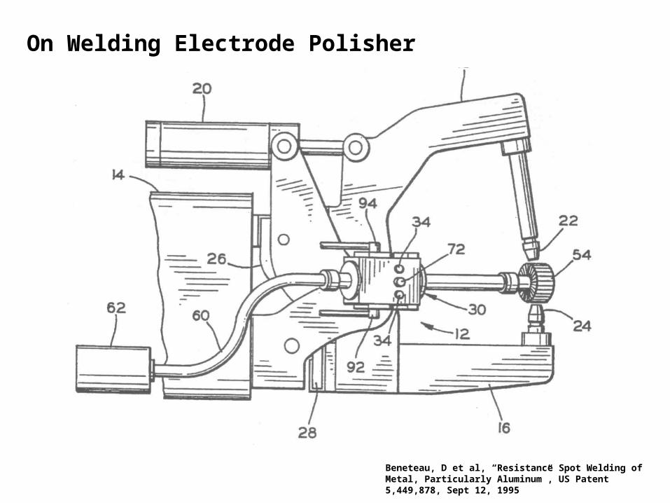
On Welding Electrode Polisher
Beneteau, D et al, “Resistance Spot Welding of Metal, Particularly Aluminum”, US Patent 5,449,878, Sept 12, 1995
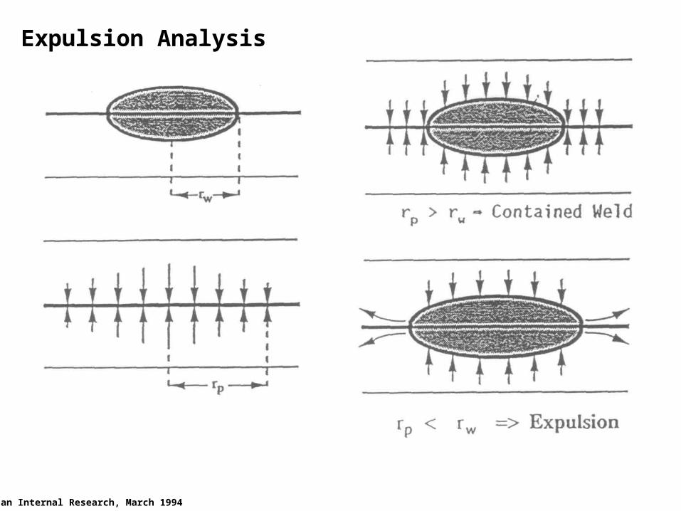
Expulsion Analysis
Alcan Internal Research, March 1994
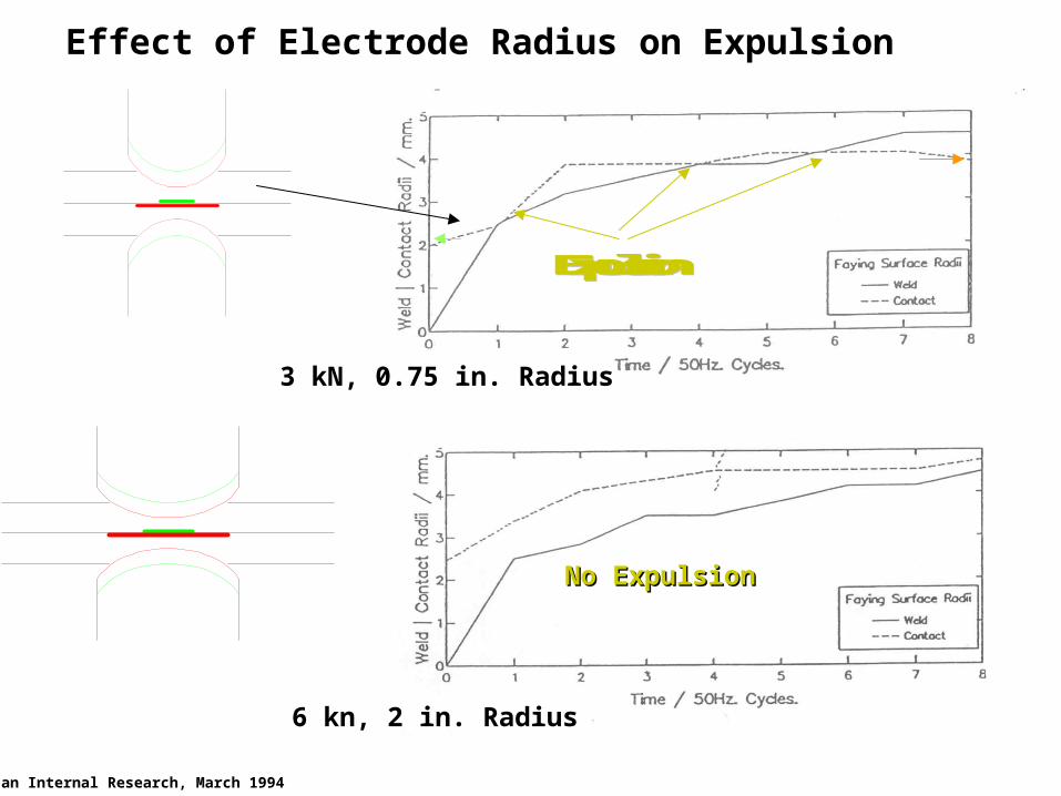
ExpulsionExpulsion
Alcan Internal Research, March 1994
3 kN, 0.75 in. Radius
6 kn, 2 in. Radius
Effect of Electrode Radius on Expulsion
No ExpulsionNo Expulsion
Required Properties of Ideal Electrodes
• Maximum electrical and thermal conductivity
• Maximum hardness or resistance to deformation
• Tip Design Which Reduces Wear
• Minimum tendency to alloy with the material being welded
(Because of Lower Resistance of Aluminum Than SteelMore Current is Needed to Make the Weld)
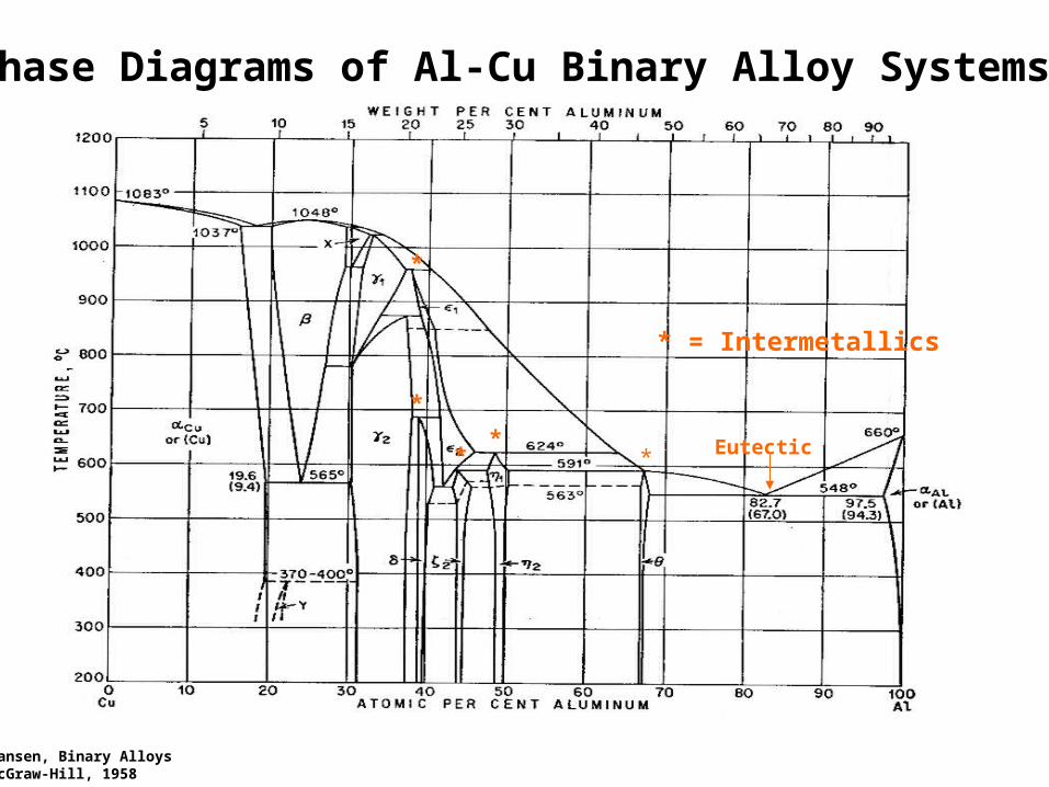
Phase Diagrams of Al-Cu Binary Alloy Systems
Hansen, Binary AlloysMcGraw-Hill, 1958
Eutectic**
*
*
*
* = Intermetallics
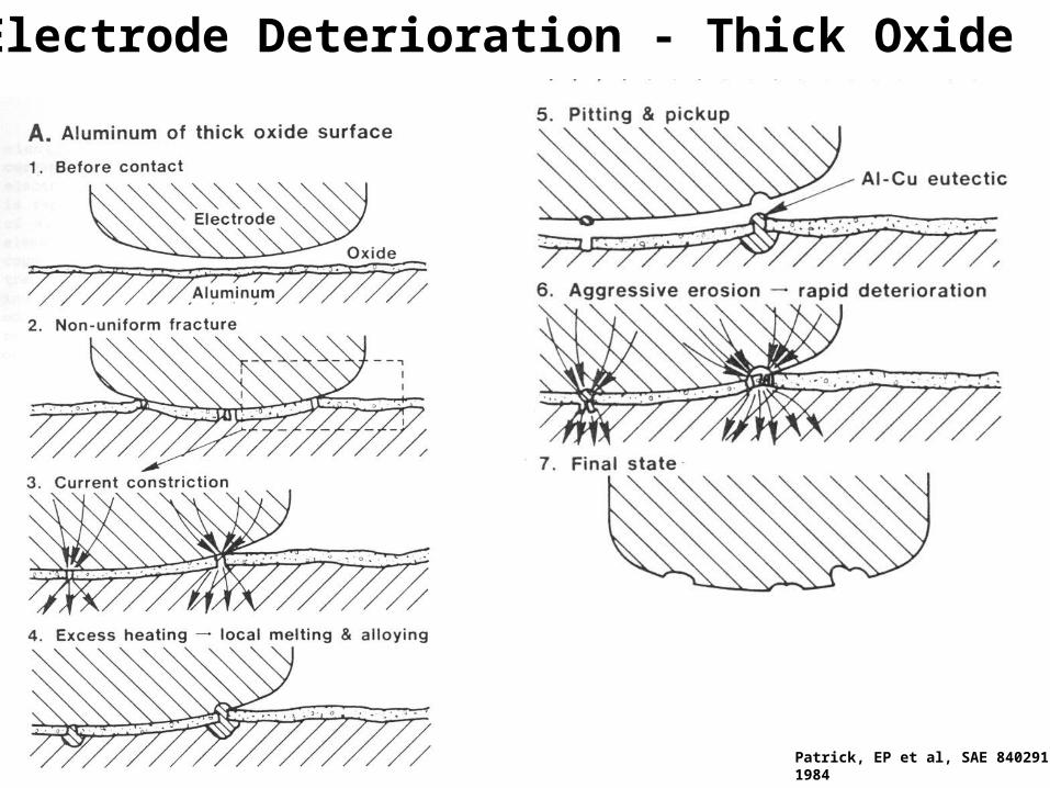
Electrode Deterioration - Thick Oxide
Patrick, EP et al, SAE 840291,1984
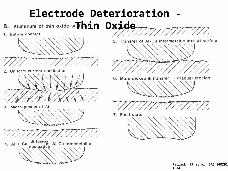
Patrick, EP et al, SAE 840291,1984
Electrode Deterioration - Thin Oxide
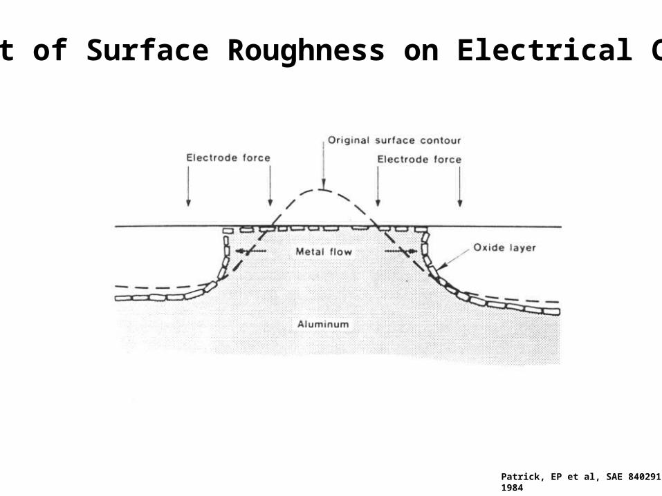
Effect of Surface Roughness on Electrical Contact
Patrick, EP et al, SAE 840291,1984
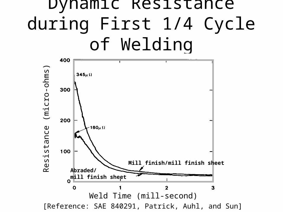
Dynamic Resistance during First 1/4 Cycle of Welding
Mill finish/mill finish sheet
Weld Time (mill-second)
Re
sist
ance
(m
icro
-oh
ms)
Abraded/mill finish sheet
[Reference: SAE 840291, Patrick, Auhl, and Sun]
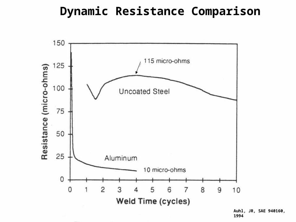
Dynamic Resistance Comparison
Auhl, JR, SAE 940160,1994
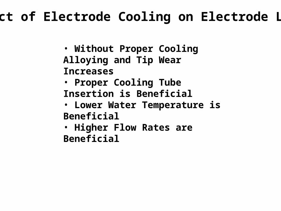
Effect of Electrode Cooling on Electrode Life
• Without Proper Cooling Alloying and Tip Wear Increases• Proper Cooling Tube Insertion is Beneficial• Lower Water Temperature is Beneficial• Higher Flow Rates are Beneficial
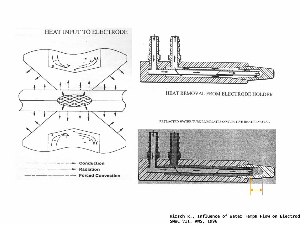
Hirsch R., Influence of Water Temp& Flow on Electrode LifeSMWC VII, AWS, 1996
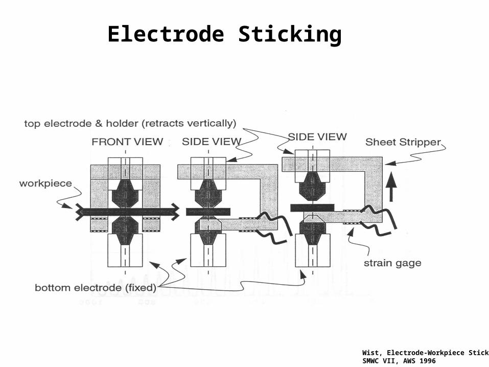
Electrode Sticking
Wist, Electrode-Workpiece StickingSMWC VII, AWS 1996
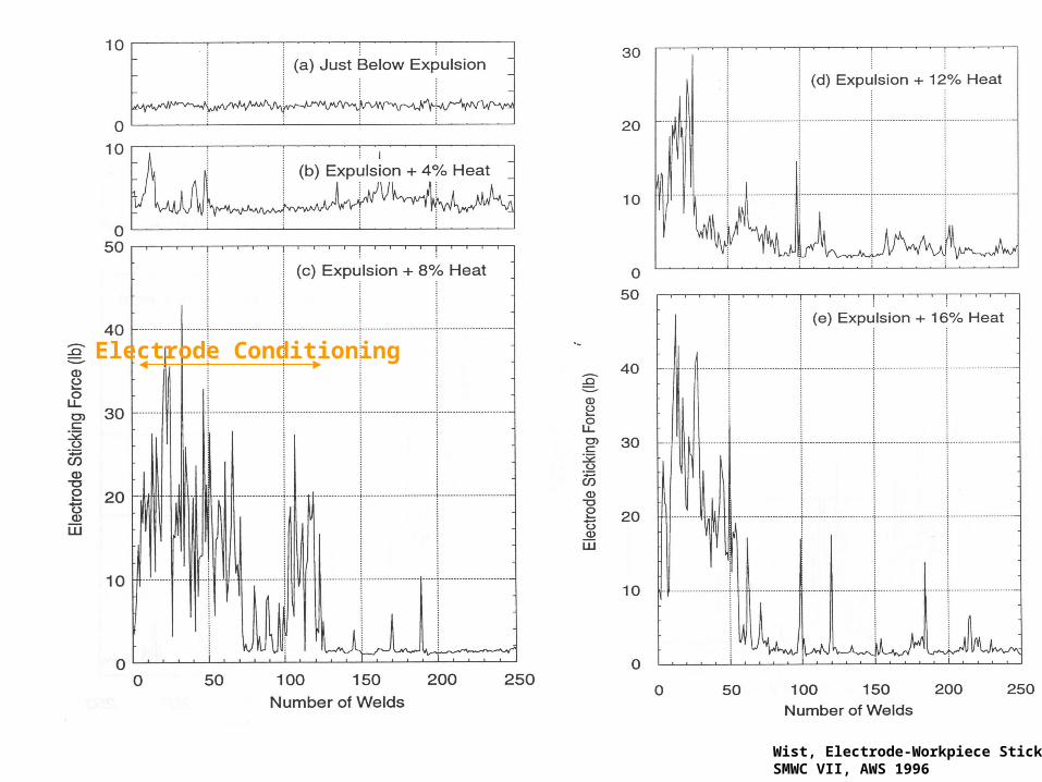
Electrode Conditioning
Wist, Electrode-Workpiece StickingSMWC VII, AWS 1996