aluminium gear pumps - zoebl-hydraulik.atzoebl-hydraulik.at/dwlds/pumo/1_5pe.pdf · the salami...
TRANSCRIPT
1.5 PE
Companywith quality systemcertified by DNVUNI EN ISO 9001/2008
Aluminium gear pumps
E0.
109.
0114
.14.
00-IM
00
Tecnical Catalogue and Dealer management

The Salami Company is one of the best Italian engineering excellences in the field of fluid power
applied to mobile applications.
It was founded in 1956 with specific guidelines that have led the brand to identify Salami as a
symbol of Warranty and Reliability in its sector, in Italy and in the World.
Salami Hydraulics proudly manufactures in Italy and it has remained loyal in time to its three
strengths dictated by its founder.
Quality, Innovation and Service have made the brand Salami recognizable and great in the world.
Through its offices in North America, Spain, France, together with its business partners, the
company distributes its own products by putting the excellence of Italian engineering at the service
of the whole world.
In this volume we present you the new range of Group 1 aluminum pumps, known as SAE AA
according to the American classification
The project 1.5PE has been developed and based on the concept of “modularity“.
Thanks to our experience of over 50 years in the production of aluminum pumps, the research
of innovative materials and advanced production technologies, the valuable advices of our
customers, our engineering team has achieved a highly efficient, reliable and extremely
customizable product.
The first part of this catalog is dedicated to the technical description of the pumps.
The second part, called Dealer management , includes the order part numbers for both single
pump and conversion kit. These informations will allow you to combine in complete autonomy the
different series of double and triple pumps configurations.
Welcome into Salami Team.
Commercial Director
Michele Piazza
www.salami.it
1.5PEGEAR PUMPS “E” SERIES
General Index
SECTION A - 1.5PE TECHNICAL CATALOGUE
FEATURES
• DEFINITION OF PRESSURES.............................................................................................A1
• GENERAL INFORMATION....................................................................................................A1
• WORKING CONDITIONS.....................................................................................................A1
• DRIVE SHAFTS....................................................................................................................A2
• DIRECTION VIEWED AT THE DRIVE SHAFT......................................................................A2
• HYDRAULIC PIPE LINE........................................................................................................A2
• DESCRIPTION OF THE PRODUCT IDENTIFICATION LABEL............................................A2
• FILTRATION INDEX RECOMMENDED................................................................................A3
• FIRE RESISTANT FLUID......................................................................................................A3
• COMMON FORMULAS FOR PUMPS..................................................................................A3
• SHAFT SEAL DESIGN, PRESSURE AND MATERIALS AVAILABLE...................................A3
• ROTATION CHANGE INSTRUCTION...................................................................................A4
• SUGGESTED COMBINATIONS OF FLANGES AND SHAFTS AVAILABLE........................A5
ASSEMBLING DIMENSIONS AND VALUES OF PRESSUR AND SPEED
• RELEASE WITH FLANGE P0 AND SHAFT 18.....................................................................A6
AVAILABLE PORTS
• THREADED PORTS.............................................................................................................A7
• FLANGED PORTS................................................................................................................A7
MULTIPLE GEAR PUMP - DIMENSIONS AND FEATURES
• RELEASE WITH FLANGE S0 AND SHAFT 80.....................................................................A8
• MULTIPLE PUMP WITH COMMON SUCTION - SUGGESTIONS.......................................A9
E0.
109.
0114
.14.
00/IM
00
1.5PE GEAR PUMPS “E” SERIES
www.salami.it
E0.
109.
0114
.14.
00/IM
00
• AVAILABLE FLANGES
• EUROPEAN STANSARDS..................................................................................................A10
• AMERICAN STANDARDS...................................................................................................A11
• AVAILABLE SHAFTS...........................................................................................................A12
• PERFORMANCE DIAGRAMS...................................................................................A13 - A17
• HOW TO ORDER 1.5PE SINGLE PUMP............................................................................A18
• HOW TO ORDER 1.5PE MULTIPLE PUMP........................................................................A19
General Index
SECTION B - 1.5PE
PUMP FOR DEALER MANAGEMENT
• 1.5PE-P18P0 - CLOCKWISE AND ANTI-CLOCKWISE ROTATION CODES.....................B1
• 1.5PE-G18P0 - CLOCKWISE AND ANTI-CLOCKWISE ROTATION CODES.....................B2
• 1.5PE-B18P0 - CLOCKWISE AND ANTI-CLOCKWISE ROTATION CODES.....................B3
• 1.5PE-P19P01 - CLOCKWISE AND ANTI-CLOCKWISE ROTATION CODES...................B4
• 1.5PE-R51S0 - CLOCKWISE AND ANTI-CLOCKWISE ROTATION CODES.....................B5
• 1.5PE-R80S0 - CLOCKWISE AND ANTI-CLOCKWISE ROTATION CODES.....................B6
• 1.5PE-R83S1 - CLOCKWISE AND ANTI-CLOCKWISE ROTATION CODES.....................B7
• 1.5PE-P59R - CLOCKWISE AND ANTI-CLOCKWISE ROTATION CODES.......................B8
• 1.5PE-B59R - CLOCKWISE AND ANTI-CLOCKWISE ROTATION CODES.......................B9
• 1.5PE-G59R - CLOCKWISE AND ANTI-CLOCKWISE ROTATION CODES....................B10
• 1.5PE-R59R - CLOCKWISE AND ANTI-CLOCKWISE ROTATION CODES.....................B11
• APPENDIX “A”.....................................................................................................................B12
• APPENDIX “B”.....................................................................................................................B13
E0.109.0114.14.00/IM00
The data on this catalogue refer to the standard product. The policy of Salami consist of a continuos impro-vement of its products. It reserves the right to change the specifications of the different products whenever necessary and without giving any information. If any doubts, please get in touch with our sales department.

1.5 PEAluminium gear pumps
Section A - Tecnical catalogue
E0.
109.
1213
.02.
00-IM
00

GEAR PUMPS “E” SERIES
www.salami.it
E0.109.1213.02.00/IM
00
A1
1.5PE
DEFINITION OF PRESSURES
Pag. 01For more information, pls. visit our web site: www.salami.it
End plateGEAR PUMP
“PG” SERIES
.
Features
E0.46.0211.02.00
P3 = Peak pressure
P2 = Intermittent operating pressure (1/3 of working time)
P1 = Continuous operating pressure
WORKING CONDITIONS
GENERAL
DEFINITION OF PRESSURES
- Pump inlet pressure (absolute pressure) 0,7 to 2,5 bar
10 to 36 psi
- Minimum operating fluid viscosity 12 mm2 / sec
- Max starting viscosity 800 mm2 / sec
- Suggested fluid viscosity range 17 - 65 mm2 / sec
- Fluid operating temperature range - 15 to 85 °C
- Fluid operating temperature range with FPM seals(Viton) - 20 to 110°C
- Hydraulic fluid mineral oil
Important:
in case of assembling of pumps without shaft seals, you have to keep the value of
min. suction pressure ( 0.7 bar (abs)) in the vane between pump and coupling too.
Lower pressure can lead to suction of oil through the front flange (seat of the shaft without seal);
this can damage seriously the pump.
Superior performance and reliability inheavy-duty hydraulic application.
Construction with large area, low-frictionbushings provide strength, high efficiency, and long life in severe operating environments.
The design includes an advanced thrust plate and seal configuration,which optimizes performance evenin high temperature and low viscosity conditions.
Double pump with common suction reduces mounting costs, allow for a small package size.
max. 20 s
1
1 - With reduction 80% of working pressure and at minimun speed.
Suggestion:to have the best behaviour and duty life of the pump/motor, use a cooling system in order to keep the fluid temperature at 60°C and viscosity at 20 cSt.In addition to the recommended filtration index of page 3.
• Superior performance and reliability in heavy-duty hydraulic application
• Construction with large area, high efficiency and long life in severe operating environments
• The design includes an advanced thrust plate and seal configuration, which optimizes performance even in high temperature and low viscosity conditions
• Double pump with common suction reduces mounting costs, allow for a small package size
• The design includes an advanced bushing and seal confi guration, which optimizes performance even in high temperature and low viscosity conditions
GEAR PUMPS “E” SERIES
www.salami.itA2
E0.
109.
1213
.02.
00/IM
00
1.5PE
DRIVE SHAFTS
Features
Pag. 02For more information, pls. visit our web site: www.salami.itE0.46.0211.02.00
DRIVE SHAFT
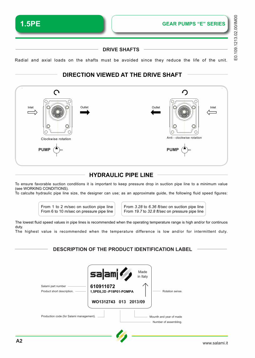
Radial and axial loads on the shafts must be avoided since they reduce the life of the unit.
HYDRAULIC PIPE LINE
To ensure favorable suction conditions it is important to keep pressure drop in suction pipe line to a minimum value
(see WORKING CONDITIONS).
To calculte hydraulic pipe line size, the designer can use; as an approximate guide, the following fluid speed figures:
From 1 to 2 m/sec on suction pipe lineFrom 6 to 10 m/sec on pressure pipe line
The lowest fluid speed values in pipe lines is recommended when the operating temperature range is high and/or for continuos
duty.
The highest value is recommended when the temperature difference is low and/or for intermittent duty.
From 3.28 to 6.36 ft/sec on suction pipe lineFrom 19.7 to 32.8 ft/sec on pressure pipe line
DIRECTION VIEWED AT THE DRIVE SHAFT
O
O
u
u
t
t
l
l
e
e
t
t
I
I
n
n
l
l
e
e
t
t
A
A
n
n
t
t
i
i
-
-
c
c
l
l
o
o
c
c
k
k
w
w
i
i
s
s
e
e
r
r
o
o
t
t
a
a
t
t
i
i
o
o
n
n
C
C
l
l
o
o
c
c
k
k
w
w
i
i
s
s
e
e
r
r
o
o
t
t
a
a
t
t
i
i
o
o
n
n
O
O
u
u
t
t
l
l
e
e
t
t
I
I
n
n
l
l
e
e
t
t
GEAR PUMP
“PG” SERIES
Inlet
Inlet
Outlet
Outlet
In case of need we can supply the flange with a threaded hole to vent the drain of the shaft seals area.As you can see on pages 10 and 11, the flanges are:
S7 with G1/8 threaded holeS8 with SAE4 threaded hole�
�
Bi - directional rotation
Pump
Motor Motor
PumpPUMP PUMP
Features
Pag. 02For more information, pls. visit our web site: www.salami.itE0.46.0211.02.00
DRIVE SHAFT
Radial and axial loads on the shafts must be avoided since they reduce the life of the unit.
HYDRAULIC PIPE LINE
To ensure favorable suction conditions it is important to keep pressure drop in suction pipe line to a minimum value
(see WORKING CONDITIONS).
To calculte hydraulic pipe line size, the designer can use; as an approximate guide, the following fluid speed figures:
From 1 to 2 m/sec on suction pipe lineFrom 6 to 10 m/sec on pressure pipe line
The lowest fluid speed values in pipe lines is recommended when the operating temperature range is high and/or for continuos
duty.
The highest value is recommended when the temperature difference is low and/or for intermittent duty.
From 3.28 to 6.36 ft/sec on suction pipe lineFrom 19.7 to 32.8 ft/sec on pressure pipe line
DIRECTION VIEWED AT THE DRIVE SHAFT
O
O
u
u
t
t
l
l
e
e
t
t
I
I
n
n
l
l
e
e
t
t
A
A
n
n
t
t
i
i
-
-
c
c
l
l
o
o
c
c
k
k
w
w
i
i
s
s
e
e
r
r
o
o
t
t
a
a
t
t
i
i
o
o
n
n
C
C
l
l
o
o
c
c
k
k
w
w
i
i
s
s
e
e
r
r
o
o
t
t
a
a
t
t
i
i
o
o
n
n
O
O
u
u
t
t
l
l
e
e
t
t
I
I
n
n
l
l
e
e
t
t
GEAR PUMP
“PG” SERIES
Inlet
Inlet
Outlet
Outlet
In case of need we can supply the flange with a threaded hole to vent the drain of the shaft seals area.As you can see on pages 10 and 11, the flanges are:
S7 with G1/8 threaded holeS8 with SAE4 threaded hole�
�
Bi - directional rotation
Pump
Motor Motor
Pump
DESCRIPTION OF THE PRODUCT IDENTIFICATION LABEL
6109110721,5PE6,5D -P19P01-POMPA
WO1312743
2

GEAR PUMPS “E” SERIES
www.salami.it
E0.109.1213.02.00/IM
00
A3
1.5PE
FILTRATION INDEX RECOMMENDED
�������
������������������ ������
��������������������������
������������������
��������������� �����
��������� �������� �����
������ �������������������
�����������
���������������
����
���
���
���
������������
���������������
���������������
���������������
����
����
����
�����������
�����������
�����������
�����������
����� �� ��
�������� ������ �����������������
�������
�
��������������������� �������
������������������
�����������������������
���������������������������
�������������������������
�������������������������
�������������� ������������
��������������������������������� ��
�
�����
�����
��������������������
��
�����
�����
������������������������
������� ������ �
������� �������
����� ����� ���
�
�
�
���
���
������
����������������
Max pressure 3 bar ( 44 psi )
Material BUNA (NBR) -15° C - 85°C
Material VITON (FPM) -20° C - 110° C
SHAFT SEAL DESIGN, PRESSURE AND MATERIALS AVAILABLE
< 200 bar - 2900 psi
10
20/19/16
Working pressure
Contamination class NAS 1638
Contamination class ISO 4406
> 200 bar - 2900 psi
9
19/18/15

1.5PE GEAR PUMPS “E” SERIES
www.salami.itA4
E0.
109.
1213
.02.
00/IM
00
Step 2:take off the front
flange, complete of shaft seal.
In case of key, it has to be taken off before
of the flange.To avoid the damage
of the shaft seal.
Step 1:unscrew and take off the 4 assembling bolts.
Step 4:take off the bushing.
Step 3:take note of the assembling position of the bronze thrust plate.If necessary, you can put a mark which help you remembering the position of the plate re-lated to the body.This is very important, because at the end you must re-assemble it in this way.
Step 6:reverse their position
and re-assemble them.
Step 5:take off both the shafts, drive and driven.
Step 8:reverse and re-
assemble the front flange.
Step 7:re-assemble the thrust plate in the same position it was at the beginning.Reference step 3.
Step 9:re-place and screw the bolts,
taking care of the torque 25 - 30 Nm.
ANTI-CLOCKWISE
ROTATION CHANGE INSTRUCTION
OutletInlet
CLOCKWISE
telnIteltuO
RELEASE SHOWED R83S1
The instruction is valid for all the configurations.
SPOOL CONTROLS
1.5PEGEAR PUMPS “E” SERIES
www.salami.it
E0.109.1213.02.00/IM
00
A5
1,6PE
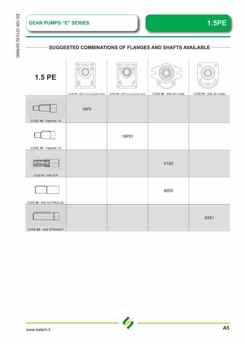
CODE P0 - (Ø25,4 mm) European stand. CODE P01 - (Ø30 mm) European stand. CODE S0 - SAE AA 2 bolts CODE S1 - SAE AA 4 bolts
CODE 18 - Tapered 1:8
18P0
19P01
CODE 19 - Tapered 1:8
19P01
CODE 51 - SAE A 9T
51S0
CODE 80 - SAE AA PARALLEL
80S0
83S1
CODE 83 - SAE STRAIGHT
SUGGESTED COMBINATIONS OF FLANGES AND SHAFTS AVAILABLE
1.5 PE
1.5PE GEAR PUMPS “E” SERIES
www.salami.itA6
E0.
109.
1213
.02.
00/IM
00
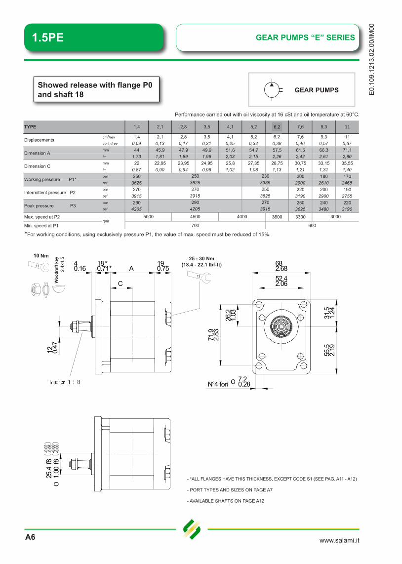
Showed release with flange P0and shaft 18
*For working conditions, using exclusively pressure P1, the value of max. speed must be reduced of 15%.
cm3/rev 1,4 2,1 2,8 3,5 4,1 5,2 6,5 7,6 9,3 11cu.in./rev 0,09 0,13 0,17 0,21 0,25 0,32 0,40 0,46 0,57 0,67mm 44 45,9 47,9 49,9 51,6 54,7 57,5 61,5 66,3 71,1in 1,73 1,81 1,89 1,96 2,03 2,15 2,26 2,42 2,61 2,80mm 22 22,95 23,95 24,95 25,8 27,35 28,75 30,75 33,15 35,55in 0,87 0,90 0,94 0,98 1,02 1,08 1,13 1,21 1,31 1,40bar 250 200 180 170psi 3625 2900 2610 2465bar 270 220 200 190psi 3915 3190 2900 2755bar 290 250 240 220psi 4205 3625 3480 3190
Max. speed at P2 3600 3300
Min. speed at P1rpm
290
2503625270
11
2303335
Working pressure P1*250
3625270
3915
3915
5000 4500 4000
700 600
4205
3000
1,4 2,1 2,8 7,6 9,3
Dimension A
3,5 6,5
Displacements
4,1 5,2TYPE
Peak pressure P3
Dimension C
Intermittent pressure P2
Performance carried out with oil viscosity at 16 cSt and oil temperature at 60°C.
682.6852.42.06
71.9
2.83
26.2
1.03 31
.51.
2455
.52.
19
O 7.20.28N°4 fori
40.16
180.71 A
C
190.75
12 0.47
25.4
f8-0
.02
-0.0
5
1.00
f8-0
.00
-0.0
0O
25 - 30 Nm(18.4 - 22.1 lbf-ft)
13
* *11
10
2.4x
4.5
- *ALL FLANGES HAVE THIS THICKNESS, EXCEPT CODE S1 (SEE PAG. A11 - A12)
- PORT TYPES AND SIZES ON PAGE A7
- AVAILABLE SHAFTS ON PAGE A12
6,2
6,20,38

1.5PEGEAR PUMPS “E” SERIES
www.salami.it
E0.109.1213.02.00/IM
00
A7
AVAILABLE PORTS
code B
code P
TYPE
Ø D Ø A d e Ø D Ø A d e13 30 13 12 30 13
0,51 1,18 0,51 0,47 1,18 0,51
INLET OUTLET
From 1.4 to 11 M6 M6
TYPE
Ø D Ø A d e Ø D Ø A d e13 30 13 12 30 13
0,51 1,18 0,51 0,47 1,18 0,51
INLET OUTLET
From 1.4 to 11 M6 M6
code G British standard pipe parallel (BSPP)
TYPEA B C Y A B C Y
15 18 30 13 13 250,59 0,71 1,18 0,51 0,51 0,9815 18 30 15 13 30
0,59 0,71 1,18 0,59 0,51 1,18
INLET OUTLET
From 1.4 to 6.2 G1/2" G3/8"
From 7.6 to 11 G1/2" G1/2"
code R SAE threaded (ODT)
TYPEA B C Y K A B C Y K
3/4" 14,5 17,3 30 2,5 9/16" 13 13 25 2,516 UNF 0,57 0,68 1,18 0,10 18 UNF 0,51 0,51 0,98 0,10
7/8" 16,7 20,2 34 2,5 3/4" 14,5 15 30 2,514 UNF 0,66 0,80 1,34 0,10 16 UNF 0,57 0,59 1,18 0,10
INLET OUTLET
From 1.4 to 6.2
From 7.6 to 11

www.salami.itA8
E0.
109.
1213
.02.
00/IM
00
6.40.25
12.7
0.50
O
14.1
20.
56
190.75
50.8
f8-0
.030
-0.0
76
2.00
0f8
-0.0
01-0
.003
O
85.2
53.
36
32 1.26
53.2
52.
10
C C
A A180.71
451.77
102.64.04
10.3
0.41
823.23
12 0.47
*For working conditions, using exclusively pressure P1, the value of max. speed must be reduced of 15%.
Performance carried out with oil viscosity at 16 cSt and oil temperature at 60°C.
MULTIPLEMULTIPLE Showed release with flange S0 and shaft 80
cm3/rev 1,4 2,1 2,8 3,5 4,1 5,2 6,5 7,6 9,3 11cu.in./rev 0,09 0,13 0,17 0,21 0,25 0,32 0,40 0,46 0,57 0,67mm 44 45,9 47,9 49,9 51,6 54,7 57,5 61,5 66,3 71,1in 1,73 1,81 1,89 1,96 2,03 2,15 2,26 2,42 2,61 2,80mm 22 22,95 23,95 24,95 25,8 27,35 28,75 30,75 33,15 35,55in 0,87 0,90 0,94 0,98 1,02 1,08 1,13 1,21 1,31 1,40bar 250 200 180 170psi 3625 2900 2610 2465bar 270 220 200 190psi 3915 3190 2900 2755bar 290 250 240 220psi 4205 3625 3480 3190
Max. speed at P2 3600 3300
Min. speed at P1rpm
290
2503625270
11
2303335
Working pressure P1*250
3625270
3915
3915
5000 4500 4000
700 600
4205
3000
1,4 2,1 2,8 7,6 9,3
Dimension A
3,5 6,5
Displacements
4,1 5,2TYPE
Peak pressure P3
Dimension C
Intermittent pressure P2
25 - 30 Nm(18.4 - 22.1 lbf-ft)
13
Max. torque 30Nm (266 lbf in)
- *ALL FLANGES HAVE THIS THICKNESS, EXCEPT CODE S1 (SEE PAG. A11 - A12)
- PORT TYPES AND SIZES ON PAGE A7
- AVAILABLE SHAFTS ON PAGE A12
- COMMON SUCTION PORT SIZE ON PAGE A9
GEAR PUMPS “E” SERIES1.5PE
6,2
6,20,38
www.salami.it
E0.109.1213.02.00/IM
00
A9
GEAR PUMPS “E” SERIES 1.5PE
RELEASE WITH REAR PORTS
www.salami.it
########
Sal
ami S
.p.A
. Via
Em
ilia O
vest
, 411
23 M
oden
a te
l. +3
9 05
9 38
7411
exp
ort@
sala
mi.i
t
#####
####
RELEASE WITH REAR PORTS
www.salami.it
########
Sal
ami S
.p.A
. Via
Em
ilia O
vest
, 411
23 M
oden
a te
l. +3
9 05
9 38
7411
exp
ort@
sala
mi.i
t
#####
####
24
68
1012
1416
1820
2224
2628
3032
3436
409,
213
,015
,918
,420
,622
,624
,426
,027
,629
,130
,531
,933
,234
,535
,736
,838
,039
,141
,20,
666
0,99
91,
332
1,66
51,
998
2,33
12,
664
2,99
73,
330
3,66
33,
996
4,32
94,
662
4,99
55,
328
5,66
15,
994
6,32
76,
660
6,5
8,0
9,2
10,3
11,3
12,2
13,0
13,8
14,6
15,3
15,9
16,6
17,2
17,8
18,4
19,0
19,5
20,1
20,6
0,33
30,
500
0,66
60,
833
0,99
91,
166
1,33
21,
499
1,66
51,
832
1,99
82,
165
2,33
12,
498
2,66
42,
831
2,99
73,
164
3,33
05,
77,
08,
19,
09,
910
,711
,412
,112
,813
,414
,014
,615
,115
,616
,216
,717
,117
,618
,10,
256
0,38
40,
512
0,64
00,
768
0,89
71,
025
1,15
31,
281
1,40
91,
537
1,66
51,
793
1,92
12,
049
2,17
72,
305
2,43
42,
562
5,3
6,5
7,5
8,4
9,2
9,9
10,6
11,3
11,9
12,5
13,0
13,6
14,1
14,6
15,0
15,5
15,9
16,4
16,8
0,22
20,
333
0,44
40,
555
0,66
60,
777
0,88
80,
999
1,11
01,
221
1,33
21,
443
1,55
41,
665
1,77
61,
887
1,99
82,
109
2,22
04,
95,
96,
97,
78,
49,
19,
710
,310
,911
,411
,912
,412
,813
,313
,714
,114
,615
,015
,30,
185
0,27
80,
370
0,46
30,
555
0,64
80,
740
0,83
30,
925
1,01
81,
110
1,20
31,
295
1,38
81,
480
1,57
31,
665
1,75
81,
850
4,6
5,6
6,5
7,3
8,0
8,6
9,2
9,8
10,3
10,8
11,3
11,7
12,2
12,6
13,0
13,4
13,8
14,2
14,6
0,16
70,
250
0,33
30,
416
0,50
00,
583
0,66
60,
749
0,83
30,
916
0,99
91,
082
1,16
61,
249
1,33
21,
415
1,49
91,
582
1,66
54,
15,
05,
86,
57,
17,
78,
28,
79,
29,
710
,110
,510
,911
,311
,612
,012
,412
,713
,00,
133
0,20
00,
266
0,33
30,
400
0,46
60,
533
0,59
90,
666
0,73
30,
799
0,86
60,
932
0,99
91,
066
1,13
21,
199
1,26
51,
332
3,8
4,6
5,3
5,9
6,5
7,0
7,5
8,0
8,4
8,8
9,2
9,6
9,9
10,3
10,6
11,0
11,3
11,6
11,9
0,11
10,
167
0,22
20,
278
0,33
30,
389
0,44
40,
500
0,55
50,
611
0,66
60,
722
0,77
70,
833
0,88
80,
944
0,99
91,
055
1,11
03,
54,
34,
95,
56,
06,
57,
07,
47,
88,
28,
58,
99,
29,
59,
810
,110
,410
,711
,00,
095
0,14
30,
190
0,23
80,
285
0,33
30,
381
0,42
80,
476
0,52
30,
571
0,61
80,
666
0,71
40,
761
0,80
90,
856
0,90
40,
951
3,3
4,0
4,6
5,1
5,6
6,1
6,5
6,9
7,3
7,6
8,0
8,3
8,6
8,9
9,2
9,5
9,8
10,0
10,3
0,08
30,
125
0,16
70,
208
0,25
00,
291
0,33
30,
375
0,41
60,
458
0,50
00,
541
0,58
30,
624
0,66
60,
708
0,74
90,
791
0,83
33,
13,
84,
34,
95,
35,
76,
16,
56,
97,
27,
57,
88,
18,
48,
78,
99,
29,
59,
70,
074
0,11
10,
148
0,18
50,
222
0,25
90,
296
0,33
30,
370
0,40
70,
444
0,48
10,
518
0,55
50,
592
0,62
90,
666
0,70
30,
740
29
36
41
46
50
54
58
62
65
68
71
74
77
80
82
85
87
90
92
3 3.5 4 4.5
RE LINEBACK TO TANK
1.8 2 2.5
SP
EE
Dm
/sec
SUCTION0.
5 1 1.3
1.5
FLO
W -
l/min
2,9
3,6
4,1
4,6
5,0
5,4
5,8
6,2
6,5
6,8
7,1
7,4
7,7
8,0
8,2
8,5
8,7
9,0
9,2
0,06
70,
100
0,13
30,
167
0,20
00,
233
0,26
60,
300
0,33
30,
366
0,40
00,
433
0,46
60,
500
0,53
30,
566
0,59
90,
633
0,66
62,
83,
43,
94,
44,
85,
25,
65,
96,
26,
56,
87,
17,
37,
67,
98,
18,
38,
68,
80,
061
0,09
10,
121
0,15
10,
182
0,21
20,
242
0,27
20,
303
0,33
30,
363
0,39
40,
424
0,45
40,
484
0,51
50,
545
0,57
50,
605
2,7
3,3
3,8
4,2
4,6
5,0
5,3
5,6
5,9
6,2
6,5
6,8
7,0
7,3
7,5
7,8
8,0
8,2
8,4
0,05
60,
083
0,11
10,
139
0,16
70,
194
0,22
20,
250
0,27
80,
305
0,33
30,
361
0,38
90,
416
0,44
40,
472
0,50
00,
527
0,55
52,
63,
13,
64,
04,
44,
85,
15,
45,
76,
06,
36,
56,
87,
07,
27,
47,
77,
98,
10,
051
0,07
70,
102
0,12
80,
154
0,17
90,
205
0,23
10,
256
0,28
20,
307
0,33
30,
359
0,38
40,
410
0,43
50,
461
0,48
70,
512
2,5
3,0
3,5
3,9
4,3
4,6
4,9
5,2
5,5
5,8
6,0
6,3
6,5
6,7
7,0
7,2
7,4
7,6
7,8
0,04
80,
071
0,09
50,
119
0,14
30,
167
0,19
00,
214
0,23
80,
262
0,28
50,
309
0,33
30,
357
0,38
10,
404
0,42
80,
452
0,47
6
m/s
ec
5 5.5 6 6.5 7
PRESSUR
PIP
E IN
TER
NA
L D
IAM
ETE
R -
mm
PIP
E IN
TER
NA
L A
RE
A -
cm2
SP
EE
D
Inle
t
teltuO
teltuO
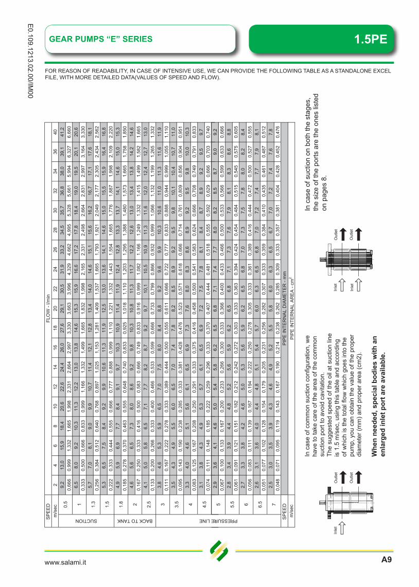
In c
ase
of c
omm
on s
uctio
n co
nfigu
ratio
n, w
e ha
ve to
take
car
e of
the
area
of t
he c
omm
on
suct
ion
port
to a
void
cav
itatio
n.Th
e su
gges
ted
spee
d of
the
oil a
t suc
tion
line
is 1
.5 m
/sec
, usi
ng th
is ta
ble
and
acco
rdin
g of
whi
ch is
the
tota
l flow
whi
ch g
oes
into
the
pum
p, y
ou c
an o
btai
n th
e va
lue
of th
e pr
oper
di
amet
er (m
m) a
nd p
rope
r are
a (c
m2)
.
Whe
n ne
eded
, spe
cial
bod
ies
with
an
enla
rged
inle
t por
t are
ava
ilabl
e.
I In nl le et tteltu
O
teltuO
In c
ase
of s
uctio
n on
bot
h th
e st
ages
, th
e si
ze o
f the
por
ts a
re th
e on
es li
sted
on
pag
es 8
.
FOR REASON OF READABILITY, IN CASE OF INTENSIVE USE, WE CAN PROVIDE THE FOLLOWING TABLE AS A STANDALONE EXCEL FILE, WITH MORE DETAILED DATA(VALUES OF SPEED AND FLOW).
1.5PE GEAR PUMPS “E” SERIES
www.salami.itA10
E0.
109.
1213
.02.
00/IM
00
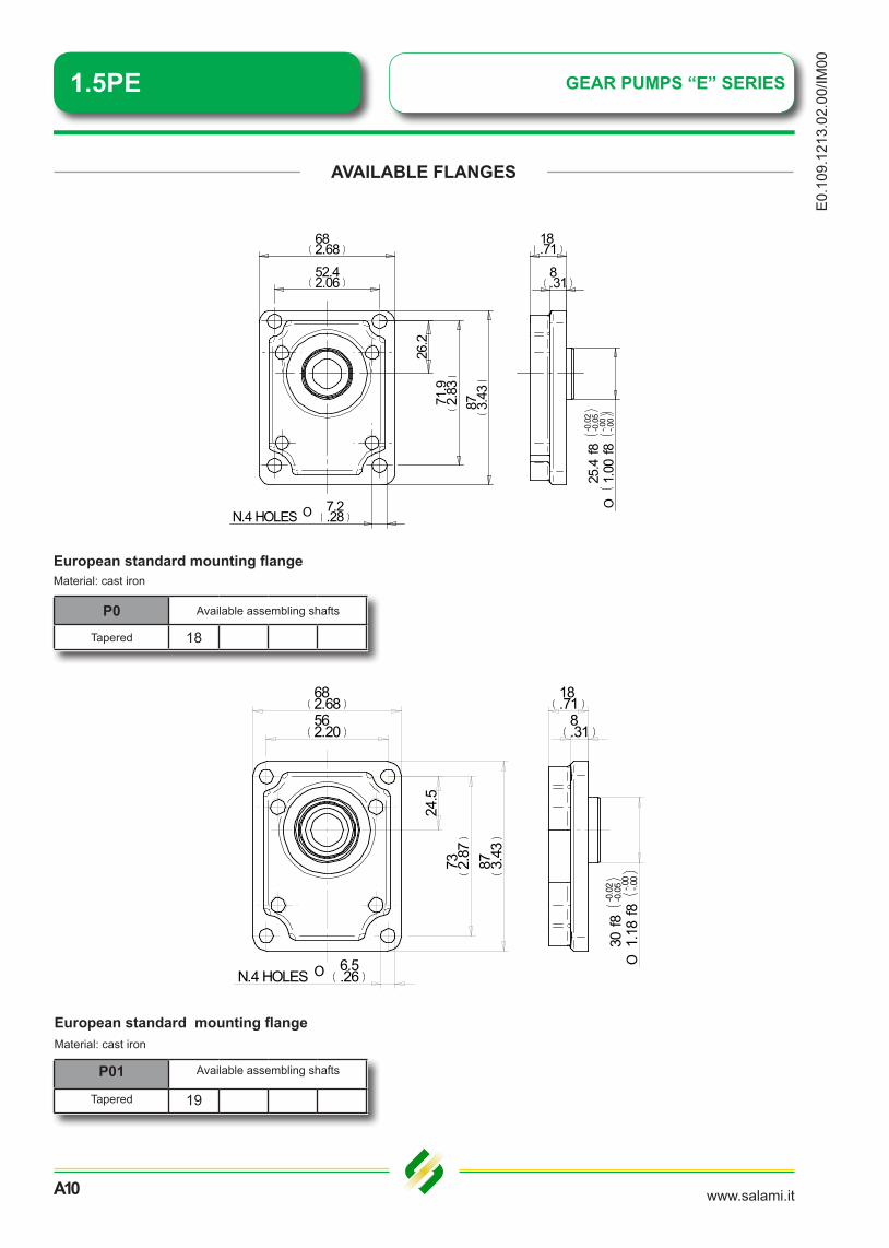
AVAILABLE FLANGES
P0 Available assembling shafts
Tapered 18
European standard mounting flange
P01 Available assembling shafts
Tapered 19
European standard mounting flangeMaterial: cast iron
Material: cast iron
682.68562.20
87 3.43
73 2.87
24.5
O 6.5.26N.4 HOLES
18.71
8.31
30f8
-0.0
2-0
.05
1.18
f8-.0
0-.0
0O
682.6852.42.06
87 3.4371
.92.
83
18.71
8.31
25.4
f8-0
.02
-0.0
5
1.00
f8-.0
0-.0
0O
O 7.2.28N.4 HOLES
26.2

1.5PEGEAR PUMPS “E” SERIES
www.salami.it
E0.109.1213.02.00/IM
00
A11
AVAILABLE FLANGES
S0 Available assembling shafts
Splined 51Straight 80
SAE AA mounting flange (2 bolts)Material: cast iron
S1 Available assembling shafts
Straight 83
SAE mounting flange (4 bolts)Material: cast iron
712.8050.82.00
71 2.80
88.5
3.4850
.82.
00
401.578.31
3.2.13
45.2
40 -0.0
5
1.78
1+.
000
-.002
O
O9 .3
5N.
4 HO
LES
102.64.04823.23
18.71
10.39
6.4.25
85 3.35
10.3
.41
50.8
0 -0.0
5
2.00
0+.
000
-.002
O
1.5PE GEAR PUMPS “E” SERIES
www.salami.itA12
E0.
109.
1213
.02.
00/IM
00
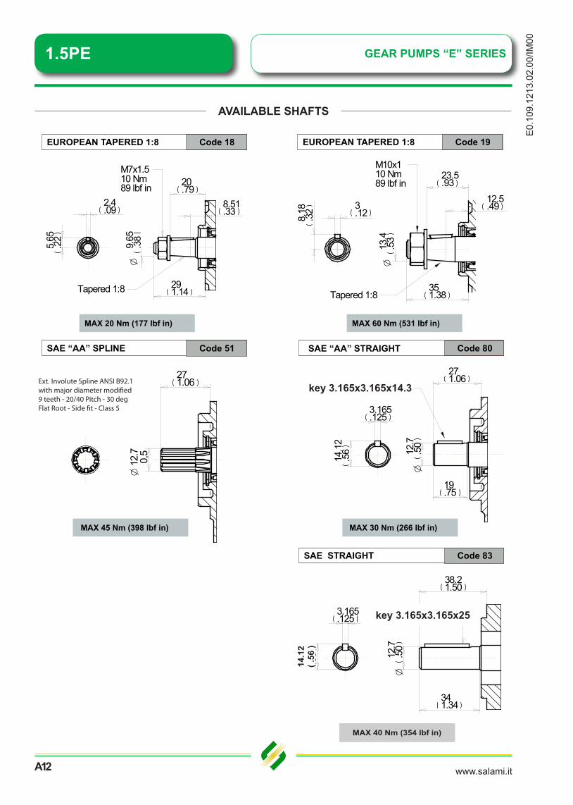
AVAILABLE SHAFTS
271.06
12.7
.50
O
19.75
14.1
2.5
6
3.165.125
key 3.165x14x3.165
EUROPEAN TAPERED 1:8 Code 18
MAX 20 Nm (177 lbf in)
SAE “AA” SPLINE Code 51
MAX 45 Nm (398 lbf in) MAX 30 Nm (266 lbf in)
SAE “AA” STRAIGHT Code 80
MAX 30 Nm (266 lbf in)
SAE STRAIGHT Code 83
38.21.50
341.34
12.7
.50
O
key 3.165x25x3.165
3.165.125
14.0
8.5
5
20.79
291.14
8.51.33
O9.
65.3
8
2.4.09
5.65
.22
M7x1.510 Nm89 lbf in
Tapered 1:8
EUROPEAN TAPERED 1:8 Code 19
23.5.93
351.38
M10x110 Nm89 lbf in
12.5.49
O13
.4.5
3
Tapered 1:8
3.128.
18.3
2MAX 60 Nm (531 lbf in)
Ext. Involute Spline ANSI B92.1with major diameter modi�ed9 teeth - 20/40 Pitch - 30 degFlat Root - Side �t - Class 5
271.06
O 1
2.7
0
,5
key 3.165x3.165x14.3
key 3.165x3.165x25
14.1
2( .
56 )
MAX 40 Nm (354 lbf in)

www.salami.it
E0.109.1213.02.00/IM
00
A13
1.5PE - 1.4
GEAR PUMPS “E” SERIES 1.5PEPerformance curves carried out with oil viscosity at 21 cSt and oil temperature at 50°CThe performance of these diagrams are approximate. In case you need approved values, please get in touch with our technical dept.
4,00
5,00
6,00
7,00
8,00
w ra
te [l
/min
]
Flow rate [l/min] 20 bar
Flow rate [l/min] 250 bar
0,00
1,00
2,00
3,00
0 1000 2000 3000 4000 5000
Flow
RPM
2,50
3,00
3,50
4,00
4,50
5,00
pow
er [k
W]
Power [kW] 50 bar
Power [kW] 100 bar
Power [kW] 150 bar
Power [kW] 200 bar
Power [kW] 250 bar
0,00
0,50
1,00
1,50
2,00
0 1000 2000 3000 4000 5000
Inpu
t
RPM
1.5PE - 2.1
0,00
1,00
2,00
3,00
4,00
5,00
6,00
7,00
8,00
9,00
10,00
0 1000 2000 3000 4000 5000
Flow
rate
[l/m
in]
RPM
1,00
1,50
2,00
2,50
3,00
3,50
4,00
4,50
5,00
5,50
6,00Power [kW] 50 barPower [kW] 100 barPower [kW] 150 barPower [kW] 200 bar
0,00
0,50
0 1000 2000 3000 4000 5000
RPM

www.salami.itA14
E0.
109.
1213
.02.
00/IM
00
1.5PE - 2.8
1.5PE GEAR PUMPS “E” SERIESPerformance curves carried out with oil viscosity at 21 cSt and oil temperature at 50°C.
The performance of these diagrams are approximate. In case you need approved values, please get in touch with our technical dept.
0,00
0,50
1,00
1,50
2,00
2,50
3,00
3,50
4,00
4,50
5,00
5,50
6,00
6,50
7,00
0 1000 2000 3000 4000 5000
Inpu
t pow
er [k
W]
RPM
Power [kW] 50 bar
Power [kW] 100 bar
Power [kW] 150 bar
Power [kW] 200 bar
Power [kW] 250 bar
0,00
1,00
2,00
3,00
4,00
5,00
6,00
7,00
8,00
9,00
10,00
11,00
12,00
13,00
14,00
15,00
0 1000 2000 3000 4000 5000
Flow
rate
[l/m
in]
RPM
Flow rate [l/min] 20 barFlow rate [l/min] 250 bar
1.5PE - 3.5
0,00
0,50
1,00
1,50
2,00
2,50
3,00
3,50
4,00
4,50
5,00
5,50
6,00
6,50
7,00
7,50
8,00
8,50
9,00
0 1000 2000 3000 4000 5000
Inpu
t pow
er [k
W]
RPM
Power [kW] 50 bar
Power [kW] 100 bar
Power [kW] 150 bar
Power [kW] 200 bar
Power [kW] 250 bar
0,00
1,00
2,00
3,00
4,00
5,00
6,00
7,00
8,00
9,00
10,00
11,00
12,00
13,00
14,00
15,00
16,00
0 1000 2000 3000 4000 5000
Flow
rate
[l/m
in]
RPM
Flow rate [l/min] 20 bar
Flow rate [l/min] 250 bar

www.salami.it
E0.109.1213.02.00/IM
00
A15
GEAR PUMPS “E” SERIES 1.5PE
1.5PE - 4.1
Performance curves carried out with oil viscosity at 21 cSt and oil temperature at 50°CThe performance of these diagrams are approximate. In case you need approved values, please get in touch with our technical dept.
0,00
0,50
1,00
1,50
2,00
2,50
3,00
3,50
4,00
4,50
5,00
5,50
6,00
6,50
7,00
7,50
8,00
8,50
9,00
0 1000 2000 3000 4000
Inpu
t pow
er [k
W]
RPM
Power [kW] 50 bar
Power [kW] 100 bar
Power [kW] 150 bar
Power [kW] 200 bar
Power [kW] 250 bar
0,00
1,00
2,00
3,00
4,00
5,00
6,00
7,00
8,00
9,00
10,00
11,00
12,00
13,00
14,00
15,00
16,00
17,00
18,00
0 1000 2000 3000 4000 5000
Flow
rate
[l/m
in]
RPM
Flow rate [l/min] 20 bar
Flow rate [l/min] 250 bar
1.5PE - 5.2
0,00
0,50
1,00
1,50
2,00
2,50
3,00
3,50
4,00
4,50
5,00
5,50
6,00
6,50
7,00
7,50
8,00
8,50
9,00
9,50
10,00
10,50
11,00
0 1000 2000 3000 4000
Inpu
t pow
er [k
W]
RPM
Power [kW] 50 bar
Power [kW] 100 bar
Power [kW] 150 bar
Power [kW] 200 bar
Power [kW] 230 bar
0,00
1,00
2,00
3,00
4,00
5,00
6,00
7,00
8,00
9,00
10,00
11,00
12,00
13,00
14,00
15,00
16,00
17,00
18,00
19,00
20,00
21,00
22,00
0 1000 2000 3000 4000 5000
Flow
rate
[l/m
in]
RPM
Flow rate [l/min] 20 bar
Flow rate [l/min] 250 bar

www.salami.itA16
E0.
109.
1213
.02.
00/IM
00
GEAR PUMPS “E” SERIES1.5PE
1.5PE - 6.2
Performance curves carried out with oil viscosity at 21 cSt and oil temperature at 50°C.The performance of these diagrams are approximate. In case you need approved values, please get in touch with our technical dept.
0,00
0,50
1,00
1,50
2,00
2,50
3,00
3,50
4,00
4,50
5,00
5,50
6,00
6,50
7,00
7,50
8,00
8,50
9,00
9,50
10,00
10,50
11,00
0 1000 2000 3000 4000
Inpu
t pow
er [k
W]
RPM
Power [kW] 50 bar
Power [kW] 100 bar
Power [kW] 150 bar
Power [kW] 200 bar
Power [kW] 230 bar
0,00
1,00
2,00
3,00
4,00
5,00
6,00
7,00
8,00
9,00
10,00
11,00
12,00
13,00
14,00
15,00
16,00
17,00
18,00
19,00
20,00
21,00
22,00
23,00
24,00
0 1000 2000 3000 4000 5000
Flow
rate
[l/m
in]
RPM
Flow rate [l/min] 20 bar
Flow rate [l/min] 250 bar
1.5PE - 7.6
0,00
0,50
1,00
1,50
2,00
2,50
3,00
3,50
4,00
4,50
5,00
5,50
6,00
6,50
7,00
7,50
8,00
8,50
9,00
9,50
10,00
10,50
11,00
0 1000 2000 3000 4000
Inpu
t pow
er [k
W]
RPM
Power [kW] 50 bar
Power [kW] 100 bar
Power [kW] 150 bar
Power [kW] 200 bar
0,00
1,00
2,00
3,00
4,00
5,00
6,00
7,00
8,00
9,00
10,00
11,00
12,00
13,00
14,00
15,00
16,00
17,00
18,00
19,00
20,00
21,00
22,00
23,00
24,00
25,00
26,00
27,00
28,00
29,00
30,00
0 1000 2000 3000 4000 5000
Flow
rate
[l/m
in]
RPM
Flow rate [l/min] 20 bar
Flow rate [l/min] 250 bar

www.salami.it
E0.109.1213.02.00/IM
00
A17
1.5PE - 9.3
1.5PEGEAR PUMPS “E” SERIESPerformance curves carried out with oil viscosity at 21 cSt and oil temperature at 50°CThe performance of these diagrams are approximate. In case you need approved values, please get in touch with our technical dept.
1.5PE - 11
0,00
0,50
1,00
1,50
2,00
2,50
3,00
3,50
4,00
4,50
5,00
5,50
6,00
6,50
7,00
7,50
8,00
8,50
9,00
9,50
10,00
10,50
11,00
0 1000 2000 3000 4000
Inpu
t pow
er [k
W]
RPM
Power [kW] 50 bar
Power [kW] 100 bar
Power [kW] 150 bar
Power [kW] 180 bar
0,001,002,003,004,005,006,007,008,009,00
10,0011,0012,0013,0014,0015,0016,0017,0018,0019,0020,0021,0022,0023,0024,0025,0026,0027,0028,0029,0030,0031,0032,0033,0034,0035,00
0 1000 2000 3000 4000 5000
Flow
rate
[l/m
in]
RPM
Flow rate [l/min] 20 bar
Flow rate [l/min] 250 bar
0,001,002,003,004,005,006,007,008,009,00
10,0011,0012,0013,0014,0015,0016,0017,0018,0019,0020,0021,0022,0023,0024,0025,0026,0027,0028,0029,0030,0031,0032,0033,0034,0035,00
0 1000 2000 3000 4000 5000
Flow
rate
[l/m
in]
RPM
Flow rate [l/min] 20 bar
Flow rate [l/min] 250 bar
0,00
0,50
1,00
1,50
2,00
2,50
3,00
3,50
4,00
4,50
5,00
5,50
6,00
6,50
7,00
7,50
8,00
8,50
9,00
9,50
10,00
10,50
11,00
0 1000 2000 3000 4000
Inpu
t pow
er [k
W]
RPM
Power [kW] 50 bar
Power [kW] 100 bar
Power [kW] 130 bar
Power [kW] 170 bar

SPOOL CONTROLS
1.5PE GEAR PUMPS “E” SERIES
www.salami.itA18
E0.
109.
1213
.02.
00/IM
00
HOW TO ORDER 1.5PE SINGLE PUMP
A D E H
P E D - P 1 8 P 0 - V
A
B
C H
2,1
CODE
NITRILE-BUTADIENE RUBBER (NBR)
FLUOROELASTOMER (VITON) V
2.1
TYPE
SERIES
GC F
DISPLACEMENTS
cm3/rev - cu.in./rev.
1,4 - 0,09
2,1 - 0,13
1.5
AVAILABLE INTERNAL SEALS
7.6 - 0.46
HOW TO ORDER 1.5PE SINGLE PUMP
B
DIMENSION
2.8
1.4
2,8 - 0,17
3.5 - 0.21
4.1 - 0.25
5.2 - 0.32
6.5 - 0.40
9.3 9.3 - 0.57
11 11 - 0.67
6.5
7.6
3.5
4.1
5.2
D G
E
F
AVAILABLE MOUNTING FLANGES (pages 11 and 12)
EUROPEAN STANDARD Ø 25,4 mm
EUROPEAN STANDARD Ø 30 mm P01
R
B
D
P
ROTATION (page 2)
CLOCKWISE
ANTI-CLOCKWISE
FLANGED PORTS EUROPEAN STANDARD
AVAILABLE PORTS (page 8)
CODE
CODE
P0
SAE AA 2 BOLTS Ø 50,8 mm S0
SAE 4 BOLTS Ø 45,24 mm S1
SAE AA 9T-20/40DP
18
GAS THREADED PORTS (BSPP)
SAE THREADED PORTS (ODT)
FLANGED PORTS GERMAN STANDARD
S
CODE
CODE
G
AVAILABLE SHAFTS (pages 13)
EUROPEAN TAPERED 1:8 SHAFT
SAE STRAIGHT
EUROPEAN TAPERED 1:8 SHAFT
SAE AA STRAIGHT
19
51
80
83
6.2 6.2 - 0.38

SPOOL CONTROLS
1.5PEGEAR PUMPS “E” SERIES
www.salami.it
E0.109.1213.02.00/IM
00
A19
HOW TO ORDER 1.5PE MULTIPLE PUMP
A D E H
P E / / D R 5 1 S 0 V U A 14 1 2 1
C GF I
HOW TO ORDER 1.5PE MULTIPLE PUMP
B
1 5 6 5P E / / D - R 5 1 S 0 - V - U A 1
A
B
C I
The number after UA means the stage where the common inlet is For
4,1 2,1
SUCTION TYPES (page 10) CODECOMMON SUCTION UA
1.4 1,4 - 0,09
DIMENSION
SERIES
TYPEDISPLACEMENTScm3/rev - cu.in./rev.
1.5 6,5
D H
The number after UA, means the stage where the common inlet is.Forexample: UA1 means the common inlet is on the first stage after the front flange.
9.3 9.3 - 0.5711 11 - 0.67
5.2 5.2 - 0.326.5 6.5 - 0.407.6 7.6 - 0.46
2.8 2,8 - 0,173.5 3.5 - 0.214.1 4.1 - 0.25
, ,2.1 2,1 - 0,13
EG
R SAE THREADED PORTS (ODT)P FLANGED PORTS EUROPEAN STANDARDB FLANGED PORTS GERMAN STANDARD
SAE 4 BOLTS Ø 45,24 mm S1
CODE AVAILABLE PORTS (page 8)G GAS THREADED PORTS (BSPP)
S ANTI-CLOCKWISE
EUROPEAN STANDARD Ø 30 mm P01SAE AA 2 BOLTS Ø 50,8 mm S0
AVAILABLE MOUNTING FLANGES (pages 11 and 12) CODE
D CLOCKWISE
EUROPEAN STANDARD Ø 25,4 mm P0
NITRILE-BUTADIENE RUBBER (NBR)CODE ROTATION (page 2)
FLUOROELASTOMER (VITON) V
AVAILABLE INTERNAL SEALS CODE
F
51 SAE AA 9T-20/40DP80 SAE AA STRAIGHT83 SAE STRAIGHT
CODE AVAILABLE SHAFTS (pages 13)18 EUROPEAN TAPERED 1:8 SHAFT19 EUROPEAN TAPERED 1:8 SHAFT
6.2 6.2 - 0.38
6,2


1.5 PEAluminium gear pumps
Section B - Dealer management
E0.
109.
1213
.05.
00-IM
00
GEAR PUMPS “E” SERIES
www.salami.it
E0.109.1213.05.00/IM
00
B1
1.5PE
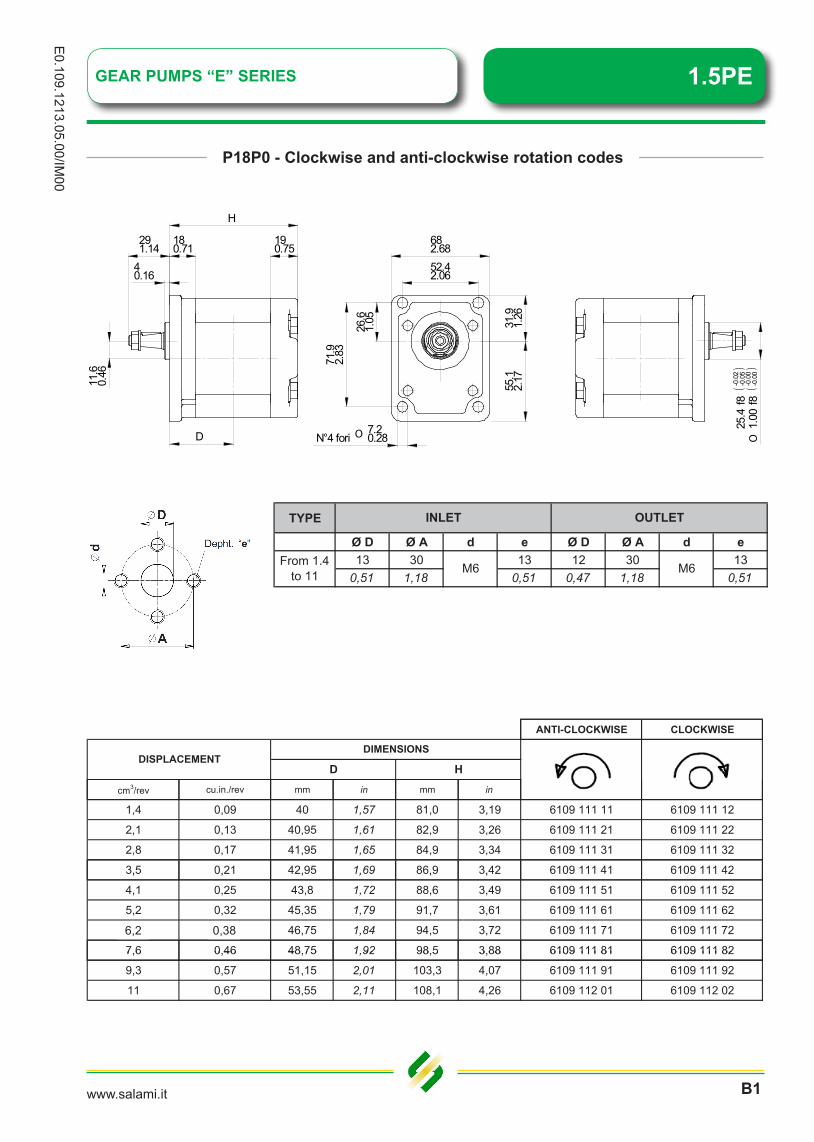
P18P0 - Clockwise and anti-clockwise rotation codes
TYPE
Ø D Ø A d e Ø D Ø A d e13 30 13 12 30 13
0,51 1,18 0,51 0,47 1,18 0,51
INLET OUTLET
From 1.4 to 11 M6 M6
682.6852.42.06
71.9
2.83
26.6
1.05 31
.91.
2655
.12.
17
O 7.20.28N°4 fori
40.16
180.71
190.75
11.6
0.46
25.4
f8-0
.02
-0.0
5
1.00
f8-0
.00
-0.0
0O
291.14
H
D
ANTI-CLOCKWISE CLOCKWISE
cm3/rev cu.in./rev mm in mm in
DISPLACEMENTDIMENSIONS
D H
1,4 0,09 40 1,57 81,0 3,19 6109 111 11 6109 111 12
2,1 0,13 40,95 1,61 82,9 3,26 6109 111 21 6109 111 22
2,8 0,17 41,95 1,65 84,9 3,34 6109 111 31 6109 111 32
3,5 0,21 42,95 1,69 86,9 3,42 6109 111 41 6109 111 423,5 0,21 42,95 1,69 86,9 3,42 6109 111 41 6109 111 42
4,1 0,25 43,8 1,72 88,6 3,49 6109 111 51 6109 111 52
5,2 0,32 45,35 1,79 91,7 3,61 6109 111 61 6109 111 62
6,5 0,40 46,75 1,84 94,5 3,72 6109 111 71 6109 111 72
7,6 0,46 48,75 1,92 98,5 3,88 6109 111 81 6109 111 827,6 0,46 48,75 1,92 98,5 3,88 6109 111 81 6109 111 82
9,3 0,57 51,15 2,01 103,3 4,07 6109 111 91 6109 111 92
11 0,67 53,55 2,11 108,1 4,26 6109 112 01 6109 112 02
6,2 0,38
1.5PE GEAR PUMPS “E” SERIES
www.salami.itB2
E0.
109.
1213
.05.
00/IM
00
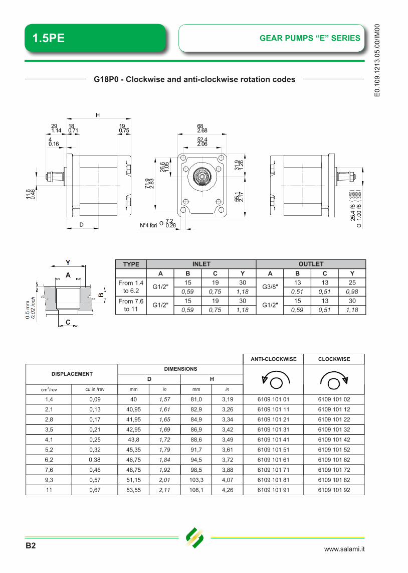
G18P0 - Clockwise and anti-clockwise rotation codes
TYPEA B C Y A B C Y
15 19 30 13 13 250,59 0,75 1,18 0,51 0,51 0,9815 19 30 15 13 30
0,59 0,75 1,18 0,59 0,51 1,18
INLET OUTLET
From 1.4 to 6.2 G1/2" G3/8"
From 7.6 to 11 G1/2" G1/2"
682.6852.42.06
71.9
2.83
26.6
1.05 31
.91.
2655
.12.
17
O 7.20.28N°4 fori
40.16
180.71
190.75
11.6
0.46
25.4
f8-0
.02
-0.0
5
1.00
f8-0
.00
-0.0
0O
291.14
H
D
ANTI-CLOCKWISE CLOCKWISE
cm3/rev cu.in./rev mm in mm in
DISPLACEMENTDIMENSIONS
D H
1,4 0,09 40 1,57 81,0 3,19 6109 101 01 6109 101 02
2,1 0,13 40,95 1,61 82,9 3,26 6109 101 11 6109 101 12
2,8 0,17 41,95 1,65 84,9 3,34 6109 101 21 6109 101 22
3,5 0,21 42,95 1,69 86,9 3,42 6109 101 31 6109 101 323,5 0,21 42,95 1,69 86,9 3,42 6109 101 31 6109 101 32
4,1 0,25 43,8 1,72 88,6 3,49 6109 101 41 6109 101 42
5,2 0,32 45,35 1,79 91,7 3,61 6109 101 51 6109 101 52
6,5 0,40 46,75 1,84 94,5 3,72 6109 101 61 6109 101 62
7,6 0,46 48,75 1,92 98,5 3,88 6109 101 71 6109 101 727,6 0,46 48,75 1,92 98,5 3,88 6109 101 71 6109 101 72
9,3 0,57 51,15 2,01 103,3 4,07 6109 101 81 6109 101 82
11 0,67 53,55 2,11 108,1 4,26 6109 101 91 6109 101 92
6,2 0,38

GEAR PUMPS “E” SERIES
www.salami.it
E0.109.1213.05.00/IM
00
B3
1.5PE
B18P0 - Clockwise and anti-clockwise rotation codes
TYPE
Ø D Ø A d e Ø D Ø A d e13 30 13 12 30 13
0,51 1,18 0,51 0,47 1,18 0,51
INLET OUTLET
From 1.4 to 11 M6 M6
682.6852.42.06
71.9
2.83
26.6
1.05 31
.91.
2655
.12.
17
O 7.20.28N°4 fori
40.16
180.71
190.75
11.6
0.46
25.4
f8-0
.02
-0.0
5
1.00
f8-0
.00
-0.0
0O
291.14
H
D
ANTI-CLOCKWISE CLOCKWISE
cm3/rev cu.in./rev mm in mm in
DISPLACEMENTDIMENSIONS
D H
1,4 0,09 40 1,57 81,0 3,19 6109 102 01 6109 102 02
2,1 0,13 40,95 1,61 82,9 3,26 6109 102 11 6109 102 12
2,8 0,17 41,95 1,65 84,9 3,34 6109 102 21 6109 102 22
3,5 0,21 42,95 1,69 86,9 3,42 6109 102 31 6109 102 323,5 0,21 42,95 1,69 86,9 3,42 6109 102 31 6109 102 32
4,1 0,25 43,8 1,72 88,6 3,49 6109 102 41 6109 102 42
5,2 0,32 45,35 1,79 91,7 3,61 6109 102 51 6109 102 52
6,5 0,40 46,75 1,84 94,5 3,72 6109 102 61 6109 102 62
7,6 0,46 48,75 1,92 98,5 3,88 6109 102 71 6109 102 727,6 0,46 48,75 1,92 98,5 3,88 6109 102 71 6109 102 72
9,3 0,57 51,15 2,01 103,3 4,07 6109 102 81 6109 102 82
11 0,67 53,55 2,11 108,1 4,26 6109 102 91 6109 102 92
6,2 0,38
1.5PE GEAR PUMPS “E” SERIES
www.salami.itB4
E0.
109.
1213
.05.
00/IM
00
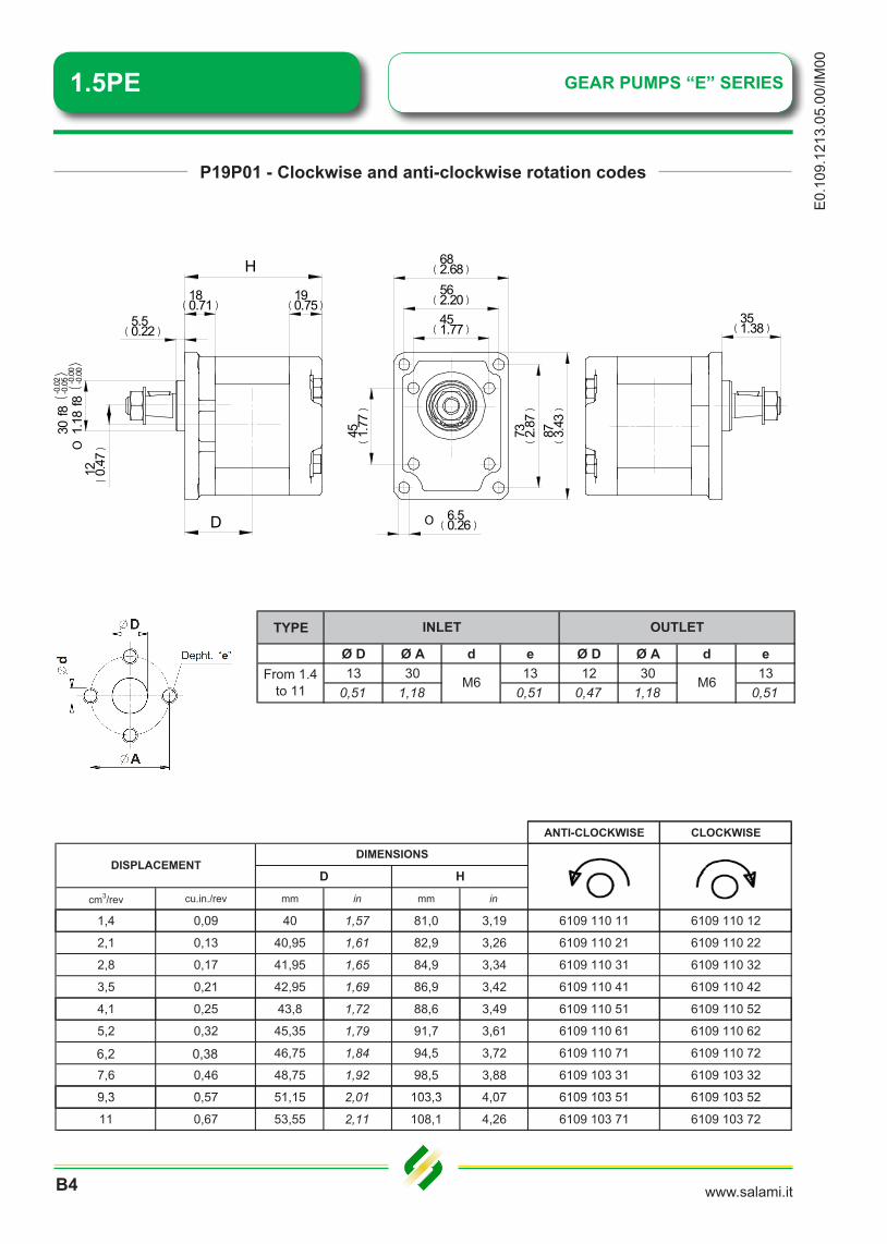
P19P01 - Clockwise and anti-clockwise rotation codes
TYPE
Ø D Ø A d e Ø D Ø A d e13 30 13 12 30 13
0,51 1,18 0,51 0,47 1,18 0,51
INLET OUTLET
From 1.4 to 11 M6 M6
ANTI-CLOCKWISE CLOCKWISE
cm3/rev cu.in./rev mm in mm in
DISPLACEMENTDIMENSIONS
D H
1,4 0,09 40 1,57 81,0 3,19 6109 110 11 6109 110 12
2,1 0,13 40,95 1,61 82,9 3,26 6109 110 21 6109 110 22
2,8 0,17 41,95 1,65 84,9 3,34 6109 110 31 6109 110 32
3,5 0,21 42,95 1,69 86,9 3,42 6109 110 41 6109 110 42
4,1 0,25 43,8 1,72 88,6 3,49 6109 110 51 6109 110 52
5,2 0,32 45,35 1,79 91,7 3,61 6109 110 61 6109 110 62
6,5 0,40 46,75 1,84 94,5 3,72 6109 110 71 6109 110 72
7,6 0,46 48,75 1,92 98,5 3,88 6109 103 31 6109 103 32
9 3 0 57 51 15 2 01 103 3 4 07 6109 103 51 6109 103 529,3 0,57 51,15 2,01 103,3 4,07 6109 103 51 6109 103 52
11 0,67 53,55 2,11 108,1 4,26 6109 103 71 6109 103 72
87 3.43
73 2.87
682.68562.20451.77
45 1.77
12 0.47
5.50.22
190.75
30f8
-0.0
2-0
.05
1.18
f8-0
.00
-0.0
0O
180.71
O 6.50.26
351.38
H
D
6,2 0,38
1.5PE
www.salami.it
E0.109.1213.05.00/IM
00
B5
GEAR PUMPS “E” SERIES
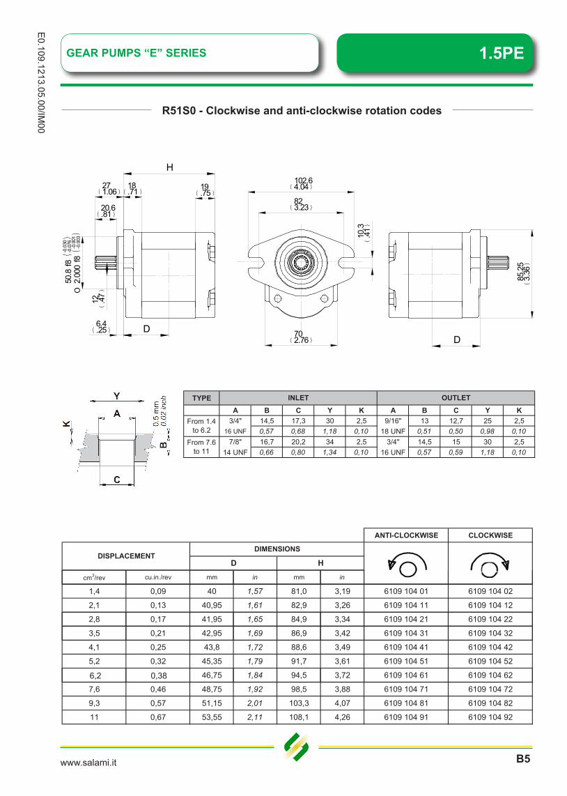
R51S0 - Clockwise and anti-clockwise rotation codes
50.8
f8-0
.030
-0.0
76
2.00
0f8
-0.0
01-0
.003
O
H
18.71 19
.75271.06
20.6.81
D6.4.25
85.2
53.
36
D
10.3
.41
102.64.04
823.23
702.76
12 .47
TYPEA B C Y K A B C Y K
3/4" 14,5 17,3 30 2,5 9/16" 13 12,7 25 2,516 UNF 0,57 0,68 1,18 0,10 18 UNF 0,51 0,50 0,98 0,10
7/8" 16,7 20,2 34 2,5 3/4" 14,5 15 30 2,514 UNF 0,66 0,80 1,34 0,10 16 UNF 0,57 0,59 1,18 0,10
From 1.4 to 6.2
From 7.6 to 11
INLET OUTLET
ANTI-CLOCKWISE CLOCKWISE
D HDISPLACEMENT
DIMENSIONS
cm3/rev cu.in./rev mm in mm in
1,4 0,09 40 1,57 81,0 3,19 6109 104 01 6109 104 02
2,1 0,13 40,95 1,61 82,9 3,26 6109 104 11 6109 104 12
2,8 0,17 41,95 1,65 84,9 3,34 6109 104 21 6109 104 22
3,5 0,21 42,95 1,69 86,9 3,42 6109 104 31 6109 104 32
4,1 0,25 43,8 1,72 88,6 3,49 6109 104 41 6109 104 42
5,2 0,32 45,35 1,79 91,7 3,61 6109 104 51 6109 104 52
6,5 0,40 46,75 1,84 94,5 3,72 6109 104 61 6109 104 62
7,6 0,46 48,75 1,92 98,5 3,88 6109 104 71 6109 104 72
9,3 0,57 51,15 2,01 103,3 4,07 6109 104 81 6109 104 82
11 0,67 53,55 2,11 108,1 4,26 6109 104 91 6109 104 92
6,2 0,38

1.5PE GEAR PUMPS “E” SERIES
www.salami.itB6
E0.
109.
1213
.05.
00/IM
00
R80S0 - Clockwise and anti-clockwise rotation codes
H271.06
20.6.81
18.71
19.75
6.4.25
12.7
.50
O
D D
14.1
2.5
6
85.2
53.
36
50.8
0 -0.0
5
20 -0.0
02O
823.23
702.76
102.64.04
R5.1
5.2012 .47
TYPEA B C Y K A B C Y K
3/4" 14,5 17,3 30 2,5 9/16" 13 12,7 25 2,516 UNF 0,57 0,68 1,18 0,10 18 UNF 0,51 0,50 0,98 0,10
7/8" 16,7 20,2 34 2,5 3/4" 14,5 15 30 2,514 UNF 0,66 0,80 1,34 0,10 16 UNF 0,57 0,59 1,18 0,10
From 1.4 to 6.2
From 7.6 to 11
INLET OUTLET
ANTI-CLOCKWISE CLOCKWISE
cm3/rev cu.in./rev mm in mm in
DISPLACEMENTDIMENSIONS
D H
1,4 0,09 40 1,57 81,0 3,19 6109 103 01 6109 103 02
2,1 0,13 40,95 1,61 82,9 3,26 6109 103 11 6109 103 12
2,8 0,17 41,95 1,65 84,9 3,34 6109 103 21 6109 103 22
3,5 0,21 42,95 1,69 86,9 3,42 6109 110 81 6109 110 82
4,1 0,25 43,8 1,72 88,6 3,49 6109 103 41 6109 103 42
5,2 0,32 45,35 1,79 91,7 3,61 6109 110 91 6109 110 92
6,5 0,40 46,75 1,84 94,5 3,72 6109 103 61 6109 103 62
7,6 0,46 48,75 1,92 98,5 3,88 6109 111 01 6109 111 02
9 3 0 57 51 15 2 01 103 3 4 07 6109 103 81 6109 103 829,3 0,57 51,15 2,01 103,3 4,07 6109 103 81 6109 103 82
11 0,67 53,55 2,11 108,1 4,26 6109 103 91 6109 103 92
6,2 0,38

1.5PEGEAR PUMPS “E” SERIES
www.salami.it
E0.109.1213.05.00/IM
00
B7
R83S1 - Clockwise and anti-clockwise rotation codes
401.57
190.75
12.7
0.5
O
38.21.5
712.8
71 2.8
88.7
53.
49
H
D D
45.2
40 -0.0
5
1.78
10 -0.0
02O
14.0
90.
55
50.8
2
50.82
O 90.35
TYPEA B C Y K A B C Y K
3/4" 14,5 17,3 30 2,5 9/16" 13 12,7 25 2,516 UNF 0,57 0,68 1,18 0,10 18 UNF 0,51 0,50 0,98 0,10
7/8" 16,7 20,2 34 2,5 3/4" 14,5 15 30 2,514 UNF 0,66 0,80 1,34 0,10 16 UNF 0,57 0,59 1,18 0,10
From 1.4 to 6.2
From 7.6 to 11
INLET OUTLET
ANTI-CLOCKWISE CLOCKWISE
cm3/rev cu.in./rev mm in mm in
HDISPLACEMENT
DIMENSIONS
D
1,4 0,09 62 2,44 103,0 4,06 6109 105 01 6109 105 02
2,1 0,13 62,95 2,48 104,9 4,13 6109 105 11 6109 105 12
2,8 0,17 63,95 2,52 106,9 4,21 6109 105 21 6109 105 22
3,5 0,21 64,95 2,56 108,9 4,29 6109 105 31 6109 105 323,5 0,21 64,95 2,56 108,9 4,29 6109 105 31 6109 105 32
4,1 0,25 65,8 2,59 110,6 4,35 6109 105 41 6109 105 42
5,2 0,32 67,35 2,65 113,7 4,48 6109 105 51 6109 105 52
6,5 0,40 68,75 2,71 116,5 4,59 6109 105 61 6109 105 62
7,6 0,46 70,75 2,79 120,5 4,74 6109 105 71 6109 105 727,6 0,46 70,75 2,79 120,5 4,74 6109 105 71 6109 105 72
9,3 0,57 73,15 2,88 125,3 4,93 6109 105 81 6109 105 82
11 0,67 75,55 2,97 130,1 5,12 6109 105 91 6109 105 92
6,2 0,38

1.5PE GEAR PUMPS “E” SERIES
www.salami.itB8
E0.
109.
1213
.05.
00/IM
00
P59R - Clockwise and anti-clockwise rotation codes
TYPE
Ø D Ø A d e Ø D Ø A d e13 30 13 12 30 13
0,51 1,18 0,51 0,47 1,18 0,51
INLET OUTLET
From 1.4 to 11 M6 M6
ANTI-CLOCKWISE CLOCKWISEANTI-CLOCKWISE CLOCKWISE
cm3/rev cu.in./rev mm in mm in
1,4 0,09 26,6 1,05 67,6 2,66 6109 311 11 6109 311 12
2,1 0,13 27,55 1,08 69,5 2,74 6109 311 21 6109 311 22
2,8 0,17 28,55 1,12 71,5 2,81 6109 311 31 6109 311 32
HDISPLACEMENT
DIMENSIONS
D
3,5 0,21 29,55 1,16 73,5 2,89 6109 311 41 6109 311 42
4,1 0,25 30,4 1,20 75,2 2,96 6109 311 51 6109 311 52
5,2 0,32 31,95 1,26 78,3 3,08 6109 311 61 6109 311 62
6,5 0,40 33,35 1,31 81,1 3,19 6109 311 71 6109 311 72
7,6 0,46 35,35 1,39 85,1 3,35 6109 311 81 6109 311 82
9,3 0,57 37,75 1,49 89,9 3,54 6109 311 91 6109 311 92
11 0,67 40,15 1,58 94,7 3,73 6109 312 01 6109 312 02
82.5
3.25
4 0.16
�
31.51.24
H
4.60.18
702.76
�4.20.17
N° 2 reference pin
451.77
22.50.89
10.5
0.41
23 0.91
� 8.50.33
N°4 holes
45 1.77
24 0.94
12 0.47
D
120.47
CLOCKWISE ANTI-CLOCKWISE
6,2 0,38

www.salami.it
E0.109.1213.05.00/IM
00
B9
GEAR PUMPS “E” SERIES 1.5PE
B59R - Clockwise and anti-clockwise rotation codes
TYPE
Ø D Ø A d e Ø D Ø A d e13 30 13 12 30 13
0,51 1,18 0,51 0,47 1,18 0,51
INLET OUTLET
From 1.4 to 11 M6 M6
ANTI-CLOCKWISE CLOCKWISE
cm3/rev cu.in./rev mm in mm in
D HDISPLACEMENT
DIMENSIONS
1,4 0,09 26,6 1,05 67,6 2,66 6109 302 01 6109 302 02
2,1 0,13 27,55 1,08 69,5 2,74 6109 302 11 6109 302 12
2,8 0,17 28,55 1,12 71,5 2,81 6109 302 21 6109 302 22
3,5 0,21 29,55 1,16 73,5 2,89 6109 302 31 6109 302 32
4,1 0,25 30,4 1,20 75,2 2,96 6109 302 41 6109 302 42
5,2 0,32 31,95 1,26 78,3 3,08 6109 302 51 6109 302 52
6,2 0,38 33,35 1,31 81,1 3,19 6109 302 61 6109 302 62
7,6 0,46 35,35 1,39 85,1 3,35 6109 302 71 6109 302 72
9 3 0 57 37 75 1 49 89 9 3 54 6109 302 81 6109 302 829,3 0,57 37,75 1,49 89,9 3,54 6109 302 81 6109 302 82
11 0,67 40,15 1,58 94,7 3,73 6109 302 91 6109 302 92
82.5
3.25
4 0.16
�
31.51.24
H
4.60.18
702.76
�4.20.17
N° 2 reference pin
451.77
22.50.89
10.5
0.41
23 0.91
� 8.50.33
N°4 holes
45 1.77
24 0.94
12 0.47
D
120.47
CLOCKWISE ANTI-CLOCKWISE
6,2 0,38

www.salami.it
E0.
109.
1213
.05.
00/IM
00
B10
GEAR PUMPS “E” SERIES1.5PE
G59R - Clockwise and anti-clockwise rotation codes
TYPEA B C Y A B C Y
15 19 30 13 13 250,59 0,75 1,18 0,51 0,51 0,9815 19 30 15 13 30
0,59 0,75 1,18 0,59 0,51 1,18
INLET OUTLET
From 1.4 to 6.2 G1/2" G3/8"
From 7.6 to 11 G1/2" G1/2"
ANTI-CLOCKWISE CLOCKWISE
cm3/rev cu.in./rev mm in mm in
D HDISPLACEMENT
DIMENSIONS
1,4 0,09 26,6 1,05 67,6 2,66 6109 301 01 6109 301 02
2,1 0,13 27,55 1,08 69,5 2,74 6109 301 11 6109 301 12
2,8 0,17 28,55 1,12 71,5 2,81 6109 301 21 6109 301 22
3,5 0,21 29,55 1,16 73,5 2,89 6109 301 31 6109 301 32
4,1 0,25 30,4 1,20 75,2 2,96 6109 301 41 6109 301 42
5,2 0,32 31,95 1,26 78,3 3,08 6109 301 51 6109 301 52
6,2 0,38 33,35 1,31 81,1 3,19 6109 301 61 6109 301 62
7,6 0,46 35,35 1,39 85,1 3,35 6109 301 71 6109 301 72
9 3 0 57 37 75 1 49 89 9 3 54 6109 301 81 6109 301 829,3 0,57 37,75 1,49 89,9 3,54 6109 301 81 6109 301 82
11 0,67 40,15 1,58 94,7 3,73 6109 301 91 6109 301 92
82.5
3.25
4 0.16
�
31.51.24
H
4.60.18
702.76
�4.20.17
N° 2 reference pin
451.77
22.50.89
10.5
0.41
23 0.91
� 8.50.33
N°4 holes
45 1.77
24 0.94
12 0.47
D
120.47
CLOCKWISE ANTI-CLOCKWISE
6,2 0,38

1.5PEGEAR PUMPS “E” SERIES
www.salami.it
E0.109.1213.05.00/IM
00
B11
R59R - Clockwise and anti-clockwise rotation codes
TYPEA B C Y K A B C Y K
3/4" 14,5 17,3 30 2,5 9/16" 13 12,7 25 2,516 UNF 0,57 0,68 1,18 0,10 18 UNF 0,51 0,50 0,98 0,10
7/8" 16,7 20,2 34 2,5 3/4" 14,5 15 30 2,514 UNF 0,66 0,80 1,34 0,10 16 UNF 0,57 0,59 1,18 0,10
From 1.4 to 6.2
From 7.6 to 11
INLET OUTLET
ANTI-CLOCKWISE CLOCKWISE
cm3/rev cu.in./rev mm in mm in
HDISPLACEMENT
DIMENSIONS
D
1,4 0,09 26,6 1,05 67,6 2,66 6109 303 01 6109 303 02
2,1 0,13 27,55 1,08 69,5 2,74 6109 303 11 6109 303 12
2,8 0,17 28,55 1,12 71,5 2,81 6109 303 21 6109 303 22
3,5 0,21 29,55 1,16 73,5 2,89 6109 303 31 6109 303 32
4,1 0,25 30,4 1,20 75,2 2,96 6109 303 41 6109 303 42
5,2 0,32 31,95 1,26 78,3 3,08 6109 303 51 6109 303 52
6,2 0,38 33,35 1,31 81,1 3,19 6109 303 61 6109 303 62
7,6 0,46 35,35 1,39 85,1 3,35 6109 303 71 6109 303 72
9 3 0 57 37 75 1 49 89 9 3 54 6109 303 81 6109 303 829,3 0,57 37,75 1,49 89,9 3,54 6109 303 81 6109 303 82
11 0,67 40,15 1,58 94,7 3,73 6109 303 91 6109 303 92
82.5
3.25
4 0.16
�
31.51.24
H
4.60.18
702.76
�4.20.17
N° 2 reference pin
451.77
22.50.89
10.5
0.41
23 0.91
� 8.50.33
N°4 holes
45 1.77
24 0.94
12 0.47
D
120.47
CLOCKWISE ANTI-CLOCKWISE
6,2 0,38
1.5PE
www.salami.itB12
E0.
109.
1213
.05.
00/IM
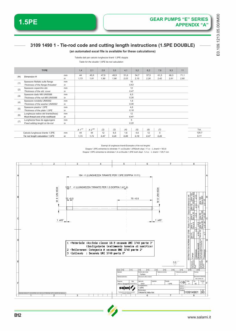
00GEAR PUMPS “E” SERIESAPPENDIX “A”
3109 1490 1 - Tie-rod code and cutting length instructions (1.5PE DOUBLE) (an automated excel file is available for these calculations)
mm 44 45,9 47,9 49,9 51,6 54,7 57,5 61,5 66,3 71,1
Tabella dati per calcolo lunghezze tiranti 1,5PE doppia
Table for the double 1,5PE tie-rod calculation
117,6 9,3
(H) Dimension H
TYPE 1,4 2,1 2,8 3,5 4,1 5,2 6,5
, , , , , , , , ,in 1,73 1,81 1,89 1,96 2,03 2,15 2,26 2,42 2,61 2,80
Spessore filettato sulle flange mmThickness of the flange threaded inSpessore coperchio std. mmThickness of the std. cover inSpessore dado M8 UNI5588 mm
160,6312
(2)
(3)
0,476,5
(H) Dimension H
(1)
Thickness of the nut M8 UNI5588 inSpessore rondella UNI6592 mmThickness of the washer UNI6592 inSpessore piastra 1,5PE mmThickness of the plate 1,5PE inLunghezza radice del tirante(fissa) mmRoot thread end of tie rod(fixed) in
(6)12
0 47
(4)
(5)
1,60,064,6
0,18
(3)0,26
Root thread end of tie-rod(fixed) inLunghezza fissa da aggiungere mmFixed adding lenght on tie-rod in
A 1 ST A 2 ND (2) (3) (4) (5) (6) (7)mm 44 44 12 6,5 1,6 4,6 12 5in 1,73 1,73 0,47 0,26 0,06 0,18 0,47 0,20
Tot.129,75,11
(7)5
0,20
Calcolo lunghezza tirante 1,5PETie rod length calculation 1,5PE
0,47
in 1,73 1,73 0,47 0,26 0,06 0,18 0,47 0,20 5,11
Doppia 1,5PE entrambe le cilindrate 11 cc/Double 1,5PEboth displ. 11 cc - L tiranti = 183,9Doppia 1,5PE entrambe le cilindrate 1,4 cc/Double 1,5PE both displ. 1,4 cc - L tiranti = 129,7 mm
Tie rod length calculation 1,5PE
Esempi di lunghezze tiranti/Examples of tie-rod lenghts
764 532 81
7632 81
D
F
A
E
B
C
A
E
B
D
F
C
Documento riservato a termini di legge con divieto di riprodurloe/o di renderlo noto a terzi senza specifica autorizzazione.
www.salami.it - +39 (0)59 387411
Particolare
Complessivo1.5PE
TIRANTE M8x184
--
310914901Sostituito da
Sostituisce il
Codice IM
00
-Modifica 00
Marco.SpaggiariFamiglia ScalaCapitolatoDisegnato Approvato Data
31/07/2013 SAGI - 1.5PE 1:1Tipo
SE
Materiale alternativo
Materiale-
-Descrizione ultima revisione
Modello stato inizialeTrafilato
-
Trattamento termico-
Trattamento superficiale-
Durezza-
- - - - - - - - -01 02 03 04 05 06 07 08 09
Quote senza indicazioneISO 2768-mK
FormatoA 3
±0.
1±
0.5
fino
a10
Tolle
ranz
a
ESTR
ATT
OD
A N
OR
MA
ISO
276
8- P
arte
1ª e
2ª-C
lass
edi
tolle
ranz
a m
K
Cam
pi
Tolle
ranz
aSm
ussi
era
ccor
di±
0.2
±0.
3±
0.2
±0.
5±
1
±0°
30'
±1°
±0
20'
±0°
10'
Scos
tam
enti
limiti
amm
essi
perd
imen
sion
ilin
eari
Scos
tam
enti
limiti
amm
essi
perd
imen
sion
ian
gola
ri
da 0
.5fin
oa
3
Cam
pidi
lung
hezz
ade
llat
o pi
u'co
rtode
ll'ang
olo
cons
ider
ato
oltre
1 0fin
oa
50ol
tre5 0
fino
a12
0ol
tre1 2
0fin
oa
400
oltre
1 20
fino
a40
0ol
tre3 0
fino
a12
0ol
tre6
fino
a30
oltre
3fin
oa
6
DISEGNO ESEGUITO CON SISTEMA CAD. NON SI AUTORIZZANO NOTE E MODIFICHE MANUALI.
3.2
8M
UN
I 453
4
1 x45°
8M
UN
I 453
4
1 x45°
13 u0.5 75 u0.5
184 u1 (LUNGHEZZA TIRANTE PER 1.5PE DOPPIA 11/11)
129,7 u1 (LUNGHEZZA TIRANTE PER 1.5 DOPPIA 1.4/1.4)
6,2

1.5PE
www.salami.it
E0.109.1213.05.00/IM
00
B13
GEAR PUMPS “E” SERIESAPPENDIX ““B”
mm 44 45,9 47,9 49,9 51,6 54,7 57,5 61,5 66,3 71,1(H) Dimension H
4,1 5,2 6,5 7,6 9,3 11
Tabella dati per calcolo lunghezze tiranti 1,5PE doppia
Table for the double 1,5PE tie-rod calculation
TYPE 1,4 2,1 2,8 3,5
, , , , , , , , ,in 1,73 1,81 1,89 1,96 2,03 2,15 2,26 2,42 2,61 2,80
Spessore filettato sulle flange mmThickness of the flange threaded inSpessore coperchio std. mmThickness of the std. cover inSpessore dado M8 UNI5588 mm
(3)6,5
(H) Dimension H
(1)16
0,63
(2)12
0,47
Thickness of the nut M8 UNI5588 inSpessore rondella UNI6592 mmThickness of the washer UNI6592 inSpessore piastra 1,5PE mmThickness of the plate 1,5PE inLunghezza radice del tirante(fissa) mmRoot thread end of tie rod(fixed) in
(5)4,6
0,18
(6)12
0 47
(3)0,26
(4)1,6
0,06
Root thread end of tie-rod(fixed) inLunghezza fissa da aggiungere mmFixed adding lenght on tie-rod in
A 1 ST A 2 ND A 3 RD (2) (3) (4) (5) (6) (7)mm 71,1 71,1 71,1 12 6,5 1,6 4,6 12 5in 2,80 2,80 2,80 0,47 0,26 0,06 0,18 0,47 0,20Tie rod length calculation 1,5PE 10,04
(7)5
0,20
Tot.Calcolo lunghezza tirante 1,5PE 255
0,47
in 2,80 2,80 2,80 0,47 0,26 0,06 0,18 0,47 0,20Tie rod length calculation 1,5PE 10,04
Esempi di lunghezze tiranti/Examples of tie-rod lenghts Tripla 1,5PE tutte le cilindrate 11 cc/Triple 1,5PE all displ. 11 cc - L tiranti = 255 mm
Tripla 1,5PE tutte le cilindrate 1,4 cc/Triple 1,5PE all displ. 1,4 cc - L tiranti = 173,7 mm
764 532 81
7632 81
D
F
A
E
B
C
A
E
B
D
F
C
Documento riservato a termini di legge con divieto di riprodurloe/o di renderlo noto a terzi senza specifica autorizzazione.
www.salami.it - +39 (0)59 387411
Particolare
Complessivo1.5PE
TIRANTE M8x255
--
310914902Sostituito da
Sostituisce il
Codice IM
00
-Modifica 00
Marco.SpaggiariFamiglia ScalaCapitolatoDisegnato Approvato Data
13/12/2013 SAGI - 1.5PE 1:1Tipo
SE
Materiale alternativo
Materiale-
-Descrizione ultima revisione
Modello stato inizialeTrafilato
-
Trattamento termico-
Trattamento superficiale-
Durezza-
- - - - - - - - -01 02 03 04 05 06 07 08 09
Quote senza indicazioneISO 2768-mK
FormatoA 3
±0.
1±
0.5
fino
a10
Tolle
ranz
a
ES
TRA
T TO
DA
NO
RM
AIS
O2 7
68-P
arte
1ªe
2 ª-C
lass
edi
tolle
ranz
am
K
Cam
pi
Tolle
ranz
aS
mus
sie
racc
ordi
±0.
2±
0.3
±0.
2±
0.5
±1
±0°
30'
±1°
±0
20'
±0°
10'
Sco
stam
enti
limiti
amm
essi
perd
imen
sio n
ilin
eari
Sco
stam
enti
limiti
amm
essi
perd
imen
sio n
ian
gola
ri
da0.
5fin
oa
3
Cam
pidi
lung
hezz
ade
llat
opi
u'co
rtode
ll'ang
olo
cons
ider
ato
oltre
10fin
oa
50ol
tre50
fino
a12
0ol
tre12
0fin
oa
400
oltre
120
fino
a40
0ol
tre30
fino
a12
0ol
tre6
fino
a30
oltre
3fin
oa
6
DISEGNO ESEGUITO CON SISTEMA CAD. NON SI AUTORIZZANO NOTE E MODIFICHE MANUALI.
3.2
8M
UN
I 453
4
1 x45°
8M
UN
I 453
4
1 x45°
13 u0.5 102 u0.5
255 u1 (LUNGHEZZA TIRANTE PER 1.5PE TRIPLA 11/11/11)
174 u1 (LUNGHEZZA TIRANTE PER 1.5 TRIPLA 1.4/1.4/1.4)
3109 1490 2 - Tie-rod code and cutting length instructions (1.5PE TRIPLE) (an automated excel file is available for these calculations)
6,2
1.5 PE
Company with quality systemcertified by DNVUNI EN ISO 9001/2008
Aluminium gear pumps
E0.
109.
0114
.14.
00-IM
00
Salami S.p.a.Via Emilia Ovest 100641100 Modena (Italy)T. +39 059 387 411F. +39 059 387 [email protected]
SALAMI ESPAÑAPoligono Industrial ArmenteresC/Primer de Maig, 18, Nave 408980 San Feliu de LlobregatBarcelonaT. +34 93 6327 288F. +34 93 6667 [email protected]
SALAMI FRANCE22, rue Louis Saillant69120 Vaulx en VelínLyonT. +33 04 7880 9941F. +33 04 7880 [email protected]
SALAMI HYDRAULICS N.A INCLoop RoadBaldwinsvilleNY 13027 USAT. +1 315 295 2363F. +1 315 295 [email protected]
www.salami.it
Tecnical Catalogue and Dealer management