alumazite 'z' - a protective corrosion inhibitive...
TRANSCRIPT


TABLE OF CONTENTS
PARAGRAPH DESCRIPTION PAGE
1 .o Introduction 2
2.0 ALUMAZITE-"Z" 2
3.0 ALUMAZITE-"Z" Its Description 3
4.0 Coating Requirements 3 Reference Nas 4006 Specification
5.0 ALUMAZITE-"Z' Test Outline 3
6.0 Test Results 5
7.0 Conclusion 11
1 .O INTRODUCTION The aerospace industry has searched with in- creasing intensity in the last few years for protec- tive coatings, due to the continuing concern of fastener and structure corrosion problems.
The use of high strength fasteners required in to- days high performance aircraft has been the basis for continued development in the search for coat- ings to eliminate the problems of electrochemical and stress corrosion related to high-strength aluminum structures.
Most present day airframe fasteners are installed in interference fit to achieve structural integrity and acquire greater structural fatigue life. This requires fastener materials to be used at ranges near their maximum capabilities, to meet design preloads for todays greater operational warranties. Problems associated with this condition are: 1. Stress-Corrosion 2. Hydrogen Enbrittlement 3. Electrochemical Corrosion 4. Temperature Extremes 5. Fatigue Corrosion 6. Chemical and Atmospheric Corrosion 7. Exfoliation 8. Installation Loeds. Plating, coatings and sealants all offer various amounts of protection. The use of high strength titanium material in the manufacturing of fasteners has become the most widely used in aerospace assemblies, but does not afford the desired corro- sion protection to the aluminum structures. These structures have been made more corrosion resis- tant by anodic or chemical conversion coatings, but failed to provide protection where holes and countersinks are drilled into the assemblies. Past procedures have been to coat these areas after drilling and before fasteners were installed. This has proved somewhat successful, but is expen- sive and creates a production problem. If not prop- erly applied it will offer little or no corrosion protec- tion. Corrosion inhibitors are being used to afford anodic or cathodic protection and are most effec- tive. They exhibit a protection of the adjacent area, sometimes referred to as an UMBRELLA or HALO EFFECT due to the ability to LEACH over and protect the immediate surrounding area.
2.0 ALUMAZITE-"2" Corrosion weakened fasteners cause serious structural problems. Selection of proper corrosion protection will greatly assure product reliability. Due to the greater length of present day opera- tional warranties of 50,000 hours and the competi- tive field of the aerospace industry, corrosion pro- tection has become of prime importance in fasten- ers and fastener assemblies. Corrosion protection covers much more than a consideration of the corrosion resistance of the fastener itself. An analysis of the assembled system includes struc- tural design materials, protective coatings; and environmental conditions.
2

3.0
4.0
The need for adequate protection against corro- sion in fastened joints has prompted Tiodize to develop a new coating system named ALUMAZITE-"Z"
ALUMAZITE-"2" Its Description ALUMAZITE-"Z' is a corrosion inhibitive organic based, aluminum filled coating developed to com- bat the corrosion problems associated with fas- teners and fastened structures. ALUMAZITE-"2" produces a permanent bonded uniform film of .0002-.0005 inches thick as applied. Corrosion in- hibitors incorporated in the coating provide protec- tion to the fastener and the adjacent structure far greater than cadmium plating, electro-deposited plating or present aluminum base systems in use.
ALUMAZITE-"Z' can be applied with conven- tional spray equipment. After the recommended bake cycle, a firm abrasion resistant and lubricated system forms. The dense low friction coating is well adapted to the requirements of interference fit fastener installation. Adhesion to the base metal will supersede all present test requirements.
ALUMINUM COATING (NAS 4006) (MIL-C-85614)
REQUlREMENTSlGENERAL 4.1 CORROSION PROTECTION
The countersunk holes and adjacent surface area of test blocks around the coated fasten- ers shall show no greater corrosion than the corresponding areas with the cadmium plated fastener in control blocks.
4.2 APPEARANCE The coating shall be smooth, uniform, matte aluminum color and shall not exhibit: 1. Pin Holes 2. Porosity 3. Blisters 4. Nodules 5. Pits 6. Other harmful imperfections
4.3 RESISTANCE TO:
4.3.1 FLUID Coating shall not show evidence of blis- tering or adhesion loss when tes?ed in hydraulic fluid at 150°F + 5°F for 30 days. It shall with stand paint strippers per MIL-R-81294 for 24 hours without loss of adhesion or blisters.
4.3.2 TEMPERATURE Coating shall with stand temperature of 475°F + 25°F for 4 hours without exhibiting blisters or loss of adhesion.
4.4 THICKNESS The coating thickness shall be .0002-.0005 which may include a base coat and shall be visible on all surfaces which can be touched by a .75 inch diameter ball.
4.5 EMBRITTLEMENT The coating shall not induce any form of stress embrittlement when the fasteners are exposed to 475°F + 25°F for 72 hours under 80% of ultimate rated load.
4.6 APPLICATION The coating must be easily applied, by con- ventional equipment and readily appliable to coating thickness.
5.0 ALUMAZITE-"Zyy TEST OUTLINE To establish the superior qualities of ALUMAZITE-"Z", tests were conducted in com- parison with systems presently in use. The test programs covered: 1. Physical Properties 2. Metallurgical 3. Electro Chemical 4. Assembly
5.1 PHYSICAL PROPERTIES To be suitable for use in aircraft structures, coatings applied to fasteners must show the following physical properties. 1. Uniform coating thickness when examined
by metallographic methods of the coating on head, shank, thread root and crest, to reflect total coating distribution.
2. Installation force requirements. One of the major functions of any coating in todays interference fit installations, often .0025 to .006 inch, requires consistent reduced in- stallation force. Testing of coatings were conducted at .0045-.005 inch diametrical interference in 7075-T6 aluminum alloy 3D stack up. REF. TABLE II PAGE 5.
3. Mechanical properties-coatings were evaluated per MIL-STD 131 2. Tension- Tension fatigue, shear and ultimate tensile strength of coated and uncoated fasteners were conducted.
4. Adhesion-Tests were conducted by the strengent impact test method, where im- pact flattens the fastener head. The impact magnitude is adjusted to deform fastener head down to the shank diameter. REF.
parts. Figure ~hiiiiv'~ imp& tester and hip&&
n
3
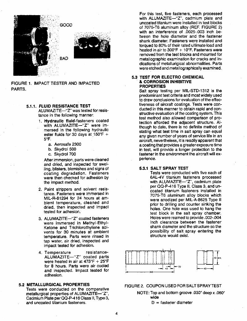
FIGURE 1. IMPACT TESTER AND IMPACTED PARTS.
5.2
5.1 .l. FLUID RESISTANCE TEST ALUMAZITE-"Z" was tested for resis- tance in the following manner: 1. Hydraulic fluid-fasteners coated
with ALUMAZITE-"Z" were im- mersed in the following hydraulic ester fluids for 30 days at 150°F + 5°F.
a. Aerosafe 2300 b. Skydrol 500 c. Skydrol 700
After immersion, parts were cleaned and dried, and inspected for swel- ling, blisters, blemishes and signs of coating degradation. Fasteners were then checked for adhesion by the impact method.
2. Paint strippers and solvent resis- tance. Fasteners were immersed in MIL-R-81294 for 24 hours at am- bient temperature, cleaned and dried, then inspected and impact tested for adhesion.
3. ALUMAZITE-"Z" coated fasteners were immersed in Methyl-Ethyl- Ketone and Trichlorothylene sol- vents for 30 minutes at ambient temperature. Parts were rinsed in tap water, air dried: inspected and impact tested for adhesion.
4. Temperature resistance- ALUMAZITE-"Z" coated parts were heated in air at 475°F + 25°F for 8 hours. Parts were air cooled and inspected. Impact tested for adhesion.
METALLURGICAL PROPERTIES Tests were conducted on the comparative metallurgical properties of ALUMAZITE-"Z", Cadmium Plate per QQ-P-416 Class II, Type 3, and uncoated titanium fasteners.
For this test, five fasteners, each processed with ALUMAZITE-"Z', cadmium plate and uncoated titanium were installed in test blocks of 7075-T6 aluminum alloy (REF. FIGURE 2) with an interference of .0025-.003 inch be- tween the hole diameter and the fastener shank diameter. Fasteners were installed and torqued to 80% of their rated ultimate load and heated in air to 300°F + 10°F. Fasteners were removed from the test blocks and mounted for metallographic examination for cracks and in- dications of metallurigical abnormalities. Parts were etched and metallographically examined.
& CORROSION INHIBITIVE PROPERTIES Salt spray testing per MIL-STD-1312 is the predominant test criteria and most widely used to draw conclusions for evaluation of the effec- tiveness of aircraft coatings. Tests were con- ducted in this manner to obtain rapid and con- structive evaluation of the coating system. This test method also allowed comparison of pro- tection afforded the adjacent structure. Al- though to date, there is no definite method of stating what test time in salt spray can equal any given number of years of service life in an aircraft, nevertheless, it is readily apparent that a coating that provides a greater exposure time in test, will provide a longer protection to the fastener in the environment the aircraft will ex- perience.
5.3 TEST FOR ELECTRO CHEMICAL
5.3.1 SALT SPRAY TEST Tests were conducted with five each of 6AL-4V titanium fasteners processed with ALUMAZITE-"Z', cadmium plate per QQ-P-416 Type II, Class 3, and un- coated titanium fasteners installed in 7075-T6 aluminum alloy blocks which were anodized per MIL-A-8625 Type II prior to drilling and counter sinking the holes. One hole was used to hang the test block in the salt spray chamber. Holes were reamed to provide .002-.004 inch clearance between the fastener shank diameter and the structure so the possibility of salt spray entering the structure would exist.
FIGURE 2. COUPON USED FOR SALTSPRAY TEST
NOTE: Top and bottom groove .030" deep x ,060' wide D = fastener diameter
4

The test coupons were assembled using the recommended fastener and nut sys- tem and were cleaned with methyl- ethyl-ketone before starting the test. The assembled test coupons were exposed to 5% salt solution, 93°F + 5°F for a period of 1000 hours, per MIL-STD- 1312. Specimen examinations were con- ducted periodically after 250, 500, 750, and 1,000 hours of exposure. Following the conclusion of each test period, one section was cut from the remainder of the coupon. The remaining portion of the coupon was cleaned with methyl-ethyl- ketone and water to remove contamina- tion caused by handling and sawing op- erations. Following this cleaning, the coupon remainder was returned to the salt spray tank for continuation of the test.
Each single fastener assembly cut from the coupon during the periodic examina- tions was examined for evidence of cor- rosive attack by removing the fastener from the isolated hole and preparing a metallographic specimen of the ex- posed test coupon. The maximum depth of corrosive attack for each coupon sec- tion was measured relative to the counter-sunk surface as shown in FI- GURE 3.
'
Cadmium Plate QP-P-416 Class 11, Type 3 ALUMAZITE " Z O
Uncoated Titanium
MAXIMUM CORROSION DEPTH
r PHOTOGRAPHED AREA
Metallic, Mechanical Electro- Chromate electro- treatment- deposited conversion deposited hydra honed from stand- treatment
ard cyanide bath
Metallic, Mechanical Sprayed 8 NIA organically treatment baked at bonded glass bead 400°F-Vz hr.
N/A Mechanical N/A NIA treatment glass bead
FIGURE 3. Countersink area shows simulated corrosion aitack in saii spray test. Area photographed to record corrosion depth.
COATING
Cadmium Plate QP-P-416 Type II Class 3
6.0 TEST RESULTS Comparison tests were conducted with the three processes listed in TABLE 1. No attempt was made for comparison with other coatings presently on the market; as all present data are based on tests using cadmium plated parts as the control specimen.
PUSH-IN FORCE DRlVABlLlTY
2680 Good 2340 2230 2510
TABLE I. MAJOR COATINGS TESTED
ALUMAZITE -"Z'
Uncoated Parts (comparison-
APPUCATION POST w i 1 PRETREATMENT I METHOD I TREATMENT I
2BQ 2498 (average)
2360 Good 21 50 2230 2500 2m
2282 (average)
2960 2880
Satisfactory
6.1
6.2
ADHESION AND COATING DISTRIBUTION 1. ALUMAZITE-"Z" exhibited excellent
adhesion to the metal substrate. Coating thickness was within the required ,0002- .0005 inch range. Distribution was uniform with no measurable build-up in thread roots.
2. Cadmium plate QQ-P-416 Type II Class 3, had good adhesion and was within the coat- ing thickness range.
INSTALLATION-PUSH-IN FORCE
Installation force to install the three types of processed pins are recorded in TABLE 2. All fasteners were lubricated with Cetyl Alcohol prior to installation test. All three configurations of test parts exhibited acceptable installation loads.
Test Data: Fastener Type: HLT 411-8-12 6AL-4V titanium alloy Stack-up: 0.75 inch 7075-TL aluminum alloy lnterfarence level: 0.0045-0.005 inch
5
6.3
(comparison- standard)
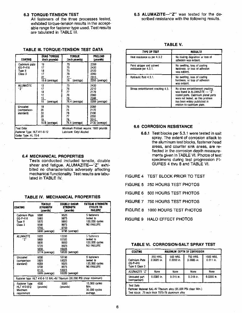
TORQU E-TENSION TEST All fasteners of the three processes tested, exhibited torque-tension results in the accept- able range for fastener type used. Test results are tabulated in TABLE 111.
20 75 21 70 22 78 2190 20 77 2200
19.8 (average) 76.4 (average) 2130 (average) E 291p_
TABLE 111. TORQUE-TENSION TEST DATA
i
PRELOAD COATING (pounds)
Test Data: Fastener Type: HLT 411-8-12 Collar Type: HL 70-8
Minimum Preload require: 1600 pounds Lubricant: Cetyl Alcohol
75 QQ-P-~I 6 I Tvoe II
250 HRS. 500 HRS. Cadmium Plate 0.0020 In. 0.0050 in. QQ-P-416
I - 15 - 78 15 (average) 76.4 (average)
750 HRS. 1000 HRS. 0.0085 in. 0.011 in.
I Uncoated I 18 I 76 I 2080 I
Type II Class 3
ALUMAZITE "Z' Uncoated part (comparison)
None None None None
0.0085 in. 0.015 in. 0.018 in. 0.0290 in.
6.4 MECHANICAL PROPERTIES Tests conducted included tensile, double shear and fatigue. ALUMAZITE-"Z" exhi- bited no characteristics adversely affecting mechanical functionality. Test results are tabu- lated in TABLE IV.
TABLE IV. MECHANICAL PROPERTIES
TENSILE DOUBLE SHEAR FATIGUE STRENGTH
(pounds) ( P O U W FAILURE COATING STRENGTH STRENGTH CYCLES TO
Cadmium Plate 5880 5 fasteners PQ-P-~I 6 tested to Type II 130,000 cycles Class 3 9975 NO FAILURE
I m 9750 I 5800 (averaae) 9795 (average) . - . . - . c "-+ ^^=-^ I
I ! ALUM.iZiiE ;(220 j g2c+ 2 iG>.eil"i>
" Z S 5800 10100 tested to 5800 9950 130,000 cycles I 5720 9925 NO FAILURE m 10225 5774 (average) 10020 (average) I
Uncoated 6030 10150 5 fasteners (comparison 5925 10025 tested to standard) 6050 9925 130.000 cycles
5730 9975 NO FAILURE 6110 5969 (average) 10020 (averaee) . _ . . .
Fastener type: HLT 410-8-12 6AL-4V Titanium (95,000 PSI shear minimum) I Fastener Type 4300 9300 15,000 cycles HLT 410-812 (pounds) (pounds) Min. Minimum 30,000 cycles requirement average.
6.5 ALUMAZITE-"Z" was tested for the de- scribed resistance with the following results.
TABLE V.
I I RESULTS TYPE OF TEST t I I Heat resistance as per 4.3.2 No coating degradion or loss of I adhesion was evident.
I No swelling, loss of coating hardness, or loss of adhesion I was evident.
Paint stripper and solvent resistance per 4.3.1. I
1 No swelling, loss of coating hardness, or loss of adhesion I was evident.
Hydraulic fluid 4.3.1. I Stress embrilement cracking 4.5.
~
No stress embrittlement cracking was found in ALUMAZITE - "Z' coated parts. Cadmium plated parts were not tested, as this problem has been widely publicized in relation to cadmium date.
6.6 CORROSION RESISTANCE
6.6.1 Test blocks Der 5.3.1 were tested in salt
FIGURE 4
FIGURE 5
FIGURE 6
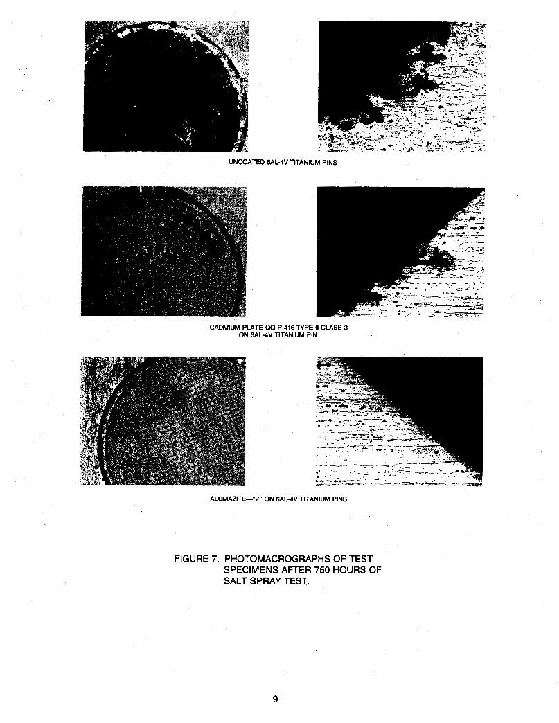
FIGURE 7
FIGURE 8
FIGURE 9
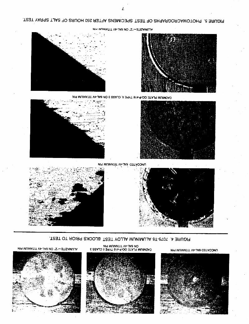
spray. The extent of corrosion attack to the aluminum test blocks, fastener head areas, and counter sink areas, are re- flected in the corrosion depth measure- ments given in TABLE VI. Photos of test specimens during test progression FI- GURES 4 thru 8 and TABLE VI.
TEST BLOCK PRIOR TO TEST
250 HOURS TEST PHOTOS
500 HOURS TEST PHOTOS
750 HOURS TEST PHOTOS
1000 HOURS TEST PHOTOS
HALO EFFECT PHOTOS
TABLE VI. CORROSION-SALT SPRAY TEST
I COATING MAXIMUM DEPTH OF CORROSION 1
Test Data Fastener Material: 6AL-4V Titanium alloy (95,000 PSI shear Min.) Test block: .75 inch thick 7075-T6 aluminum alloy
6
L
'IS31 AVtldS 11VS j0 StlnOH OS2 t l 3UV SN3VU133dS IS31 A 0 SHdVkl90kl3VNOlOHd 'S 3tlnOId
Nld WlllNVJA At-lV9 NO E SSW3 'I1 3dA.l 9 l t
Nld WnlNVlll A t l V 9 a31VO3Nfl -. \
'IS31 01 UOlUd
Nld WtllNVlll At-lV9 NO ,,Z,~-311ZVyY~lV
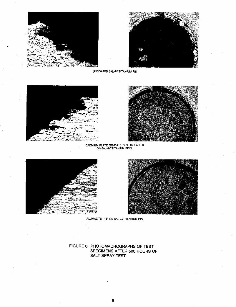
UNCOATED 6AL-4V TITANIUM PIN
CADMIUM PLATE QQ-P-416 TYPE II CLASS 3 ON 6AL-4V TITANIUM PINS.
ALUMAZITE-"2 ON 6AL-4V TITANIUM PIN
FIGURE 6. PHOTOMACROGRAPHS OF TEST SPECIMENS AFTER 500 HOURS OF SALT SPRAY TEST.
8
6
'IS31 AWdS 11VS A0 StlflOH 0SL U3UV SN3VU133dS IS31 A0 SHdVU00U3VWOIOHd 'L 3tlflE)Id
Nld WnINVlU AP-lV9 NO E SSVln3 II 3dAI QLP-d-00 31Vld WnlWQV3
SNld WtllNVlll AVlVQ aUV03Nn

01
'IS31 AVtidS 11VS do StinOH 0001 83UV SN3W133dS IS31 do SHdVti00U3VWOlOHd '8 3UnDId
Nld WfllNVlIl AP-lV9 NO .3.~-311ZVWfllV
Nld WflINVUl AV-lV9 NO E SSW3 II 3dAI SIP-d-OD 3lVld WfllWaV3
SNld WfllNVlll AV-1\19 a31V03Nfl
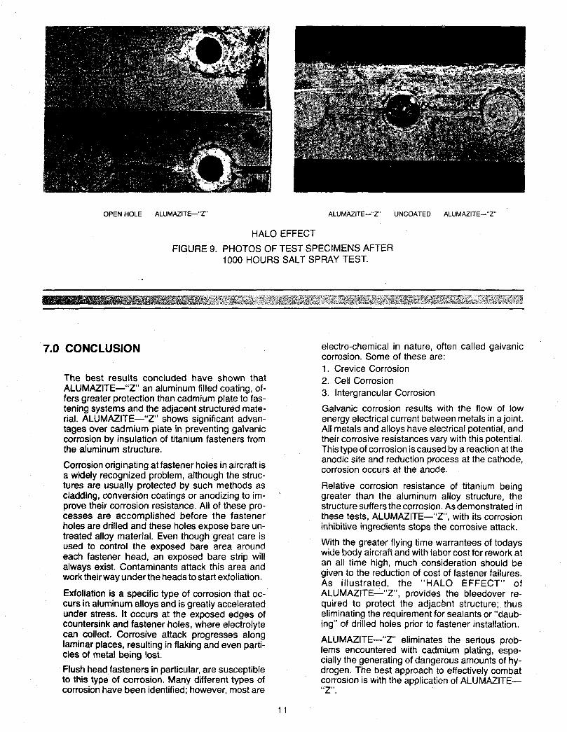
OPEN HOLE ALUMAZITE-"2' ALUMAZITE-"ZS UNCOATED ALUMAZITE--"Z'
HALO EFFECT FIGURE 9. PHOTOS OF TEST SPECIMENS AFTER
1000 HOURS SALT SPRAY TEST.
7.0 CONCLUSION
The best results concluded have shown that ALUMMITE-"2" an aluminum filled coating, of- fers greater protection than cadmium plate to fas- tening systems and the adjacent structured mate- rial. ALUMMITE-"Z' shows significant advan- tages over cadmium plate in preventing galvanic corrosion by insulation of titanium fasteners from the aluminum structure.
Corrosion originating at fastener holes in aircraft is a widely recognized problem, although the struc- tures are usually protected by such methods as cladding, conversion coatings or anodizing to im- prove their corrosion resistance. All of these pro- cesses are accomplished before the fastener hales are drilled and these holes expose bare un- treated alloy material. Even though great care is used to control the exposed bare area around each fastener head, an exposed bare strip will always exist. Contaminants attack this area and work their way under the heads to start exfoliation.
Exfoliation is a specific type of corrosion that oc- curs in aluminum alloys and is greatly accelerated under stress. It occurs at the exposed edges of countersink and fastener holes, where electrolyte can collect. Corrosive attack progresses along laminar places, resulting in flaking and even parti- cles of metal being lost. Flush head fasteners in particular, are susceptible to this type of corrosion. Many different types of corrosion have been identified; however, most are
electro-chemical in nature, often called galvanic corrosion. Some of these are: 1. Crevice Corrosion 2. Cell Corrosion 3. lntergrancular Corrosion
Galvanic corrosion results with the flow of low energy electrical current between metals in a joint. All metals and alloys have electrical potential, and their corrosive resistances vary with this potential. This type of corrosion is caused by a reaction at the anodic site and reduction process at the cathode, corrosion occurs at the anode.
Relative corrosion resistance of titanium being greater than the aluminum alloy structure, the structure suffers the corrosion. As demonstrated in these tests, ALUMAZITE-"Z", with its corrosion inhibitive ingredients stops the corrosive attack.
With the greater flying time warrantees of todays wide body aircraft ana with iabor cost tor rework at an all time high, much cofisideration should be given to the reduction of cost of fastener failures. As illustrated, the "HALO EFFECT" of ALUMAZITE-"Z", provides the bleedover re- quired to protect the adjacent structure; thus eliminating the requirement for sealants or "daub- ing" of drilled holes prior to fastener installation.
ALUMAZITE-"Z" eliminates the serious prob- lems encountered with cadmium plating, espe- cially the generating of dangerous amounts of hy- drogen. The best approach to effectively combat corrosion is with the application of ALUMAZITE- "Z".
1 1