altium i (circuit design & simulation) - ubc eceleos/pdf/e391/lec/altiumi.pdf · contents •...
TRANSCRIPT
Altium I
(Design Capture & Simulation)
ELEC391 Spring 2017

PCB Design support for ELEC391:
Altium 2016, 150 licenses
Lecture talks:
• Jan 30 Altium I (Design Capture + Simulation)
• Feb 6 Altium II (PCB Layout)
• Mar 13 Guest Lecture – PCB Production
• Support & submission instructions posted here
Mechanical and PCB design support available 2hrs per lab session, rooms MCLD315,306
Mon: 13:00-15:00 / 16:00-18:00Tue : 09:00-11:00 / 12:00-14:00 / 16:00-18:00Wed: 13:00-15:00 / 16:00-18:00Tue : 09:00-11:00 / 12:00-14:00 / 16:00-18:00

Contents
• How to install Altium Designer 2016
• Understanding Altium Designer
• Walk-through Tutorial
– Schematic Capture
– Mixed signal simulations
• SPICE basic concepts
Credits: Unless explicitly stated all source material is from the Altium website and
Altium training documents.

Typical PCB Design flow
http://e2e.ti.com/
Front-end design
and capture
Back-end design


Typical PCB Design flow
http://e2e.ti.com/
Front-end design
and capture

Altium Designer 2016A complete product development system
System requirements (MS W7, W8, W10)
• Front-end design and capture
• Physical PCB design
• FPGA hardware design
• FPGA system implementation
and debugging
• Embedded software
development
• Mixed-signal circuit simulation
• Signal integrity analysis
• PCB manufacturing

How to install Altium 2016
• Link to our download site:
https://download.ece.ubc.ca
• Useful links:
http://www.ece.ubc.ca/~leos/pages/tools/altium.html
• Create an account at Altium Live:
http://live.altium.com/#signin (slow)
email: [email protected] (fast)

Install .zip file
1
2
3
See file: README.html
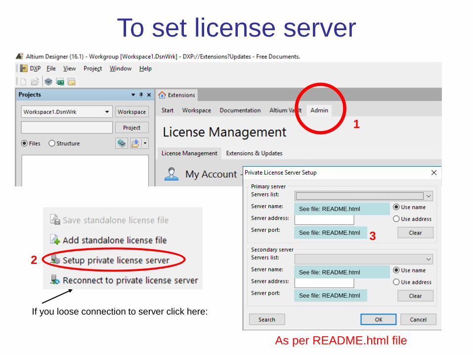
To set license server
3
1
2
As per README.html file
If you loose connection to server click here:
See file: README.html
See file: README.html
See file: README.html
See file: README.html
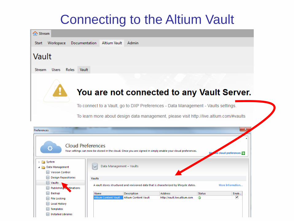
Connecting to the Altium Vault
Understanding Altium
• DXP (Design explorer): Unified platform
• Collaborative environment (corporate tool):– Multiple users, some with dedicated tasks
– Design team incremental changes day-by-day
– Built-in version control (SVN subversion or CVS concurrent versions system
– Design repositories / Vaults (accessible by multiple users with different credentials
• Cloud oriented: – Save preferences
– http://live.altium.com/ (forum, design content, blog)


Recommended basic panels
ProjectsLibraries
Messages
For more help working with panels read this
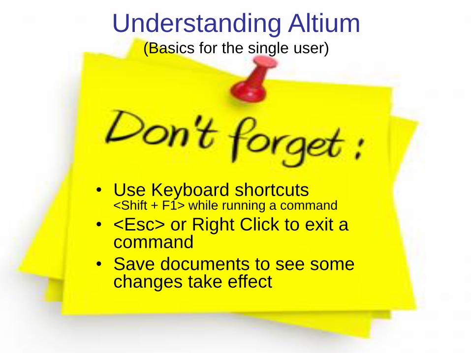
Understanding Altium(Basics for the single user)
• Use Keyboard shortcuts<Shift + F1> while running a command
• <Esc> or Right Click to exit a command
• Save documents to see some changes take effect

Understanding Altium(Basics for the single user)
• Projects (project panel, active project)
• Workspace Panels (system-wide, editor-specific)
• Editors:– Schematic
• Symbol editor
– PCB layout• Footprint editor
• CAM files (CAMtastic panel)
• Components and Libraries

Altium Projects
• Project: collection of design documents
– 1 Project = 1 implementation
– It stores links to all source documents
• relative reference: same drive
• absolute reference: different drive
– It creates links to all output documents
– Saves project options
• Create a PCB_Project, Save as: new name
(does not move the file creates a copy)
• The active project is highlighted
• Add/Remove documents to/from a project

Altium Projects: types
• PCB Project (*.PrjPcb)
– Schematic, libraries, PCB layout
• FPGA Project (*.PrjFpg)
• Embedded Project (*.PrjEmb)
• Core Project (*.PrjCor)
• Integrated Library (*.LibPkg) & (*.IntLib)
• Scritpt Project (*.PrjScr)

Component, Model and Library Concepts
• Component representations:
– Schematic symbol
– PCB footprint
– SPICE model definitions
– Signal integrity description
– 3D graphical description

Component, Model and Library Concepts
• Domains = Different phases of design
– Schematic capture
– PCB layout (2D / 3D)
– SPICE simulation
– Signal integrity analysis
• A unified component is a container with
links to all domain models + parametric
information
Different component
representations
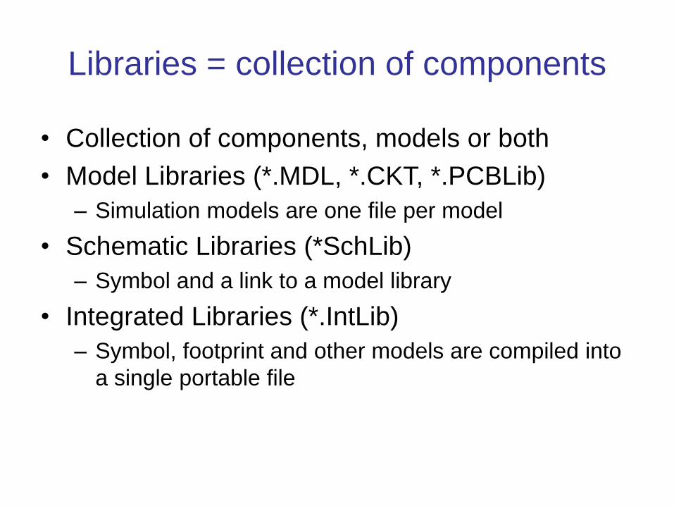
Libraries = collection of components
• Collection of components, models or both
• Model Libraries (*.MDL, *.CKT, *.PCBLib)
– Simulation models are one file per model
• Schematic Libraries (*SchLib)
– Symbol and a link to a model library
• Integrated Libraries (*.IntLib)
– Symbol, footprint and other models are compiled into
a single portable file

Project: part of and available only to the
active project and its documents
You have to keep track of where these are
if you move the project files
Installed: All installed libraries.
Components are available to all open
projects and list is persistent across
design sessions
Search Path: Additional Libraries
accessible via a search path and sub-
folders
The search paths are valid for the
active project

Libraries Panel:
All libraries available to the
active project
Project + Installed + Search
Path
When placing component:
<spacebar> to rotate
<x> or <y> to flip
<Tab> open properties dialog
<L> for PCB footprints
to flip component side
To search across libraries:
Search …
Current library
Search in current library
Set library browse mode
Select a different library
List of components.
Select the component of
interest
Schematic symbol for
selected component
Models linked to the
selected component
Graphical display of the
selected model
Icons used to show/hide
panel sections

Obtaining integrated libraries
1. Frozen (legacy) libraries: from hereyou can install anywhere but it is a good idea to make a subfolder
under:
C:\Users\Public\Public Documents\Altium\AD16\Libraryor a cloud storage service if you work from more than one PC
2. AltiumLive website: Resources / Design Content
This is useful to
preview component
This downloads a
.zip file for the complete
library

Altium Vault
Altium’s cloud library (repository of models)
Also includes real-time supply chain
information

Learning to use Altium
Best training material is on the Altium website
It is updated, but beware that menus and options
slightly change between versions
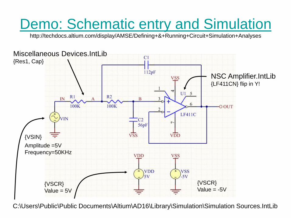
Demo: Schematic entry and Simulationhttp://techdocs.altium.com/display/AMSE/Defining+&+Running+Circuit+Simulation+Analyses
C:\Users\Public\Public Documents\Altium\AD16\Library\Simulation\Simulation Sources.IntLib
Miscellaneous Devices.IntLib{Res1, Cap}
NSC Amplifier.IntLib{LF411CN} flip in Y!
Amplitude =5V
Frequency=50KHz
{VSCR}
Value = 5V
{VSIN}
{VSCR}
Value = -5V

Set simulation parameters

Set simulation parameters

Wiring Tips
• Left-click or <Enter> to anchor the wire at the cursor position.
• <Backspace> () to remove the last anchor point.
• <Spacebar> to toggle the direction of the corner.
• <Shift+Spacebar> to cycle through all possible corner modes.
• Right-click or <Esc> to exit wire placement mode.
• To graphically edit the shape of a wire, Click once to select it first, then Click and hold on a segment or vertex to move it.
• Whenever a wire crosses the connection point of a component, or is terminated on another wire, a junction will automatically be created.
• A wire that crosses the end of a pin will connect to that pin, even if you delete the junction.
• To move a placed component and drag connected wires with it, hold down the Ctrl key while moving the component, or select Move » Drag.

About SPICE
• Berkley (class project +Masters), CANCER Computer Analysis of Nonlinear Circuits Excluding
Radiation
• Berkley (PhD) , Simulation Program with Integrated Circuit Emphasis
SPICE 1972 FORTRAN
SPICE 2 1975, SPICE 2G6 1983
SPICE 3 1989 C, SPICE 3F5 1993
SPICE 4 2004 (RF)
• Proprietary versions of SPICE SPICE-like simulators or “Alphabet SPICE”HSpice, XSPICE (Georgia Tech), PSPICE, etc

Altium and SPICE
• Altium Designer is compatible with:– SPICE3f5 (Berkley SPICE)
– XSPICE (Georgia Tech)
– PSPICE (Micro/Sim/Orcad/Cadence)
• You may need to change the file extension to
.mdl or .ckt
SUBCKT / .ENDS
• Other models need to be manually converted!

SPICE Models and Subcircuits
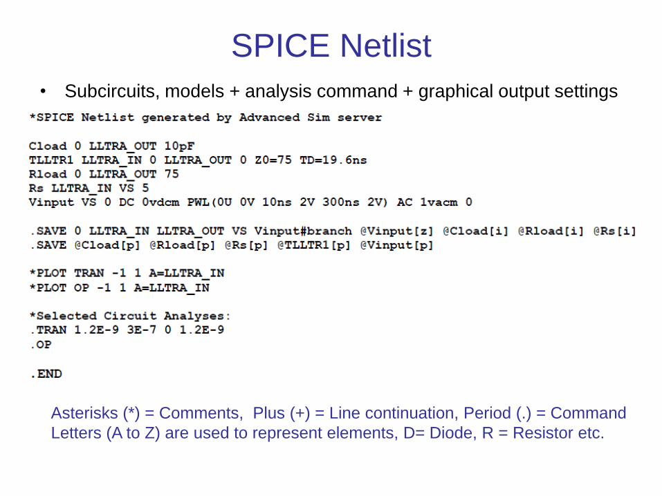
SPICE Netlist
• Subcircuits, models + analysis command + graphical output settings
Asterisks (*) = Comments, Plus (+) = Line continuation, Period (.) = Command
Letters (A to Z) are used to represent elements, D= Diode, R = Resistor etc.
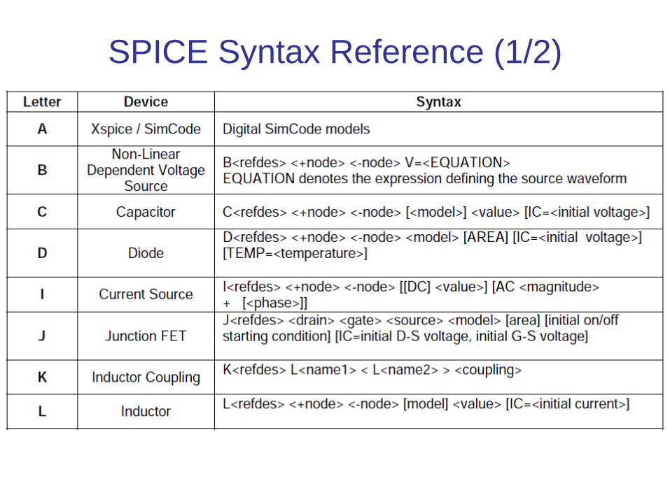
SPICE Syntax Reference (1/2)
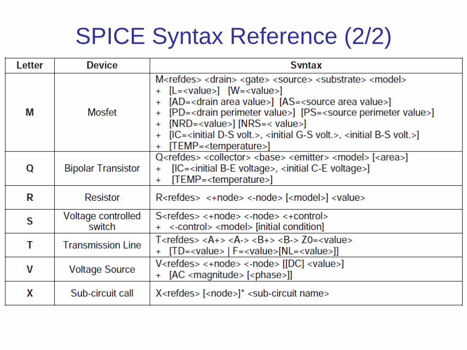
SPICE Syntax Reference (2/2)
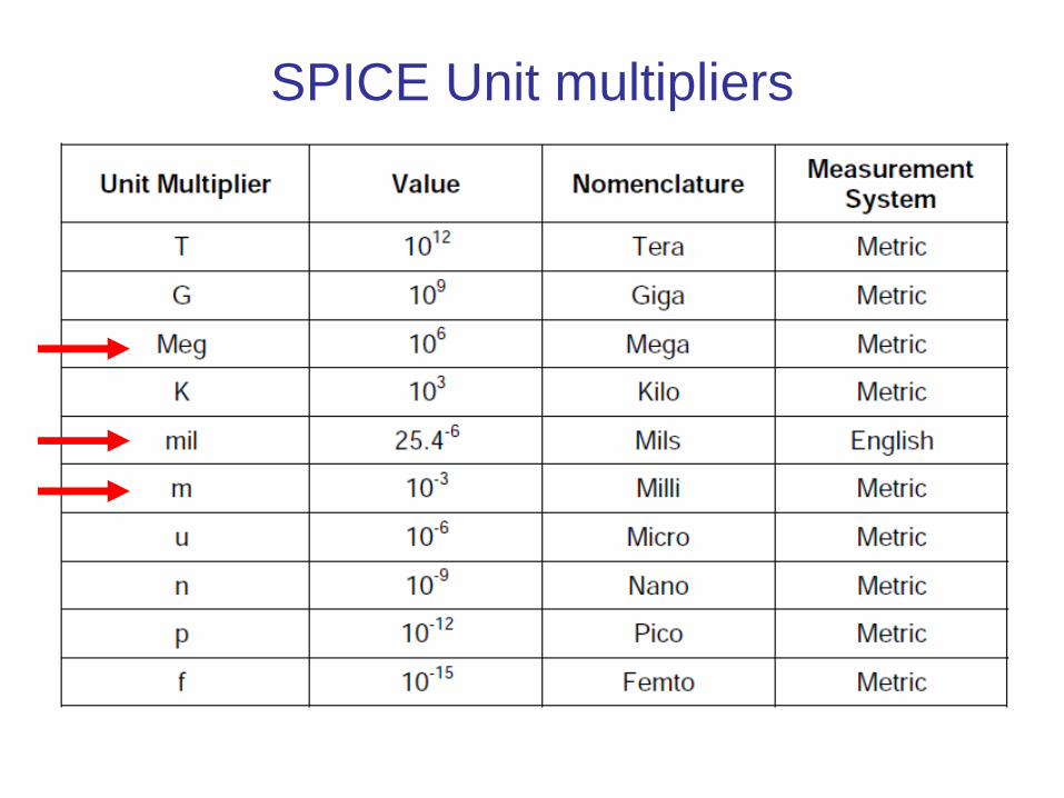
SPICE Unit multipliers