alterpath manager e2000, 2500, and 5000 installation...
TRANSCRIPT

AlterPath™ Manager E2000, 2500, and 5000 Installation, Configuration, and
User’s GuideSoftware Version 1.4.1
Cyclades Corporation3541 Gateway BoulevardFremont, CA 94538 USA1.888.CYCLADES (292.5233)1.510.771.61001.510.771.6200 (fax)http://www.cyclades.comRelease Date: April 2006Part Number: PAC0380

©2005 Cyclades Corporation
This document contains proprietary information of Cyclades Corporation and is not to be disclosed or used except in accordance with applicable contracts or agreements.
Information in this document is subject to change without notice.
All trademarks, trade names, logos and service marks referenced herein, even when not specifically marked as such, belong to their respective companies and are not to be considered unprotected by law.
The following are registered or registration-pending trademarks of Cyclades Corporation: Cyclades and AlterPath.
ActiveX, Microsoft, Microsoft Internet Explorer, Windows, and Windows NT are registered trademarks of Microsoft Corporation in the United States and other countries.
AIX is a registered trademark of International Business Machines Corporation in the United States and other countries.
FreeBSD is a registered trademark of the FreeBSD Foundation.
HP/UX is a registered trademark of the Hewlett Packard Corporation.
Linux is a registered trademark of Linus Torvalds in the United States and other countries.
Mozilla and Mozilla Firefox are trademarks of the Mozilla Foundation.
Sun, Sun Microsystems, Java, J2SE, Solaris, are trademarks or registered trademarks of Sun Microsystems, Inc. in the United States and other countries.
UNIX is a registered trademark of The Open Group in the United States and other countries.
Cisco and Cisco Systems are registered trademarks of Cisco Systems, Inc.
Juniper Networks is a registered trademark of Juniper Networks, Inc.
Nortel is a registered trademark of Nortel Networks, Inc.
AppGATE, appGATE, and MindTerm are trademarks of appGATE Network Security AB, Götenborg, Sweden
U.S. Robotics is a registered trademark of U.S. Robotics Corporation.
Hayes and the Hayes logo are trademarks of Hayes Microcomputers.
All rights reserved. This document may not, in whole or part, be copied, photocopied, reproduced, translated, or converted to any electronic or machine-readable form without the prior written consent of Cyclades Corporation.

Before You Begin ................................................. xxvAudience ...........................................................................................xxvDocument Organization ...................................................................xxviTypographic and Other Conventions ..............................................xxviiLinux Shell Syntax ..........................................................................xxixAdditional Resources .......................................................................xxxi
Cyclades Technical Training Available .......................................xxxiCyclades Firmware Upgrades ......................................................xxxiCyclades Technical Support ........................................................xxxii
Chapter 1: Introduction............................................. 1Connectivity and Capacity ....................................................................1Key Features .........................................................................................3
Single Point Security Gateway .........................................................5Java based appGATE™ MindTerm™ V3.0.1 ..................................5Centralized Authentication ...............................................................6Consolidated Views and Console Access .........................................6Access Control List (ACL) for Devices ............................................6Centralized Data Logging System ....................................................7Log File Compression and Rotation .................................................8
Prioritized Triggers & Alarms .......................................................8Other Alarm Features ........................................................................8Modem Support for Remote Sites .....................................................8Dial Back Support for ACS ..............................................................9One Time Password support for ACS ...............................................9Multiport Ethernet ...........................................................................10Enhanced Ethernet Port Configuration ...........................................10Ethernet Bonding ............................................................................10DHCP Option for APM Network Setup .........................................11
Contents

ii APM Installation, Configuration, and User’s Guide
Health Monitoring ...........................................................................11Console Wizard ...............................................................................11Device Discovery ............................................................................12Support for KVM/net ......................................................................12Support for KVM/net Plus ..............................................................12KVM/net FW Upgrade Support ......................................................13Support for OnSite ..........................................................................13Support for IPMI .............................................................................13Support for HP OpenView NNM ....................................................13Device, Console, and User Group Management .............................14Blade Module ..................................................................................14Backup, Restore, and Replicate User Data .....................................14Change and Configuration Management .........................................14Exhaustive Reporting ......................................................................15Fault Tolerant Configuration Support .............................................15Simple and Easy Web User Interface ..............................................15Command Line Interface (CLI) .......................................................16Interoperability, Integration, and Compatibility .............................16
APM E2000, 2500, and 5000 Database Compatibility ................16Interoperability with Routers and Ethernet Switches ..................16Interoperability with Cyclades Devices .......................................17Interoperability and Compatibility with Modem Vendors ..........17
Power Management Support ...........................................................17KVM/net Support ...............................................................................18
Typical Configuration of AlterPath Manager and KVM ................18AlterPath Manager Features Unsupported by KVM/net .................19
OnSite Support ....................................................................................19Example Configuration of an APM and an OnSite .........................20
Chapter 2: AlterPath Manager Installation ............ 21Product Installation Checklist .............................................................21Rack Mounting the AlterPath Manager ..............................................24Deploying the AlterPath Manager ......................................................26
Private Network Topology ..............................................................26Single Network Topology ...............................................................26Private Network Diagram ................................................................27

Contents iii
Single Network Diagram .................................................................28Safety Considerations When Rack Mounting .....................................28Pre-Configuration Requirements ........................................................30
Web Browser Requirements ............................................................32IPMI and Blade Module Options ....................................................39Verifying your Current IPMI and Blade Capability ........................40Verifying your MAC Address .........................................................41
Chapter 3: User Level Web Access........................ 43User Interface Overview .....................................................................43
General Screen Features ..............................................................46Sorting a List Form by Column/Field Name ...............................47Search and Filter Functions .........................................................47Online Help ..................................................................................48
Alarms .................................................................................................48Alarm Logs ......................................................................................48Alarms List Form ............................................................................49
Web Access for Users .........................................................................53Consoles/Devices ............................................................................53Consoles ..........................................................................................56
Multiple Users and Read/Write Access .......................................59Viewing an IBM Blade Center, Blade, or Switch .......................59Consoles Detail Form ..................................................................59KVM/net Plus Web Control Page ................................................63
IPMI ....................................................................................................67Logs ....................................................................................................68
Access Logs .................................................................................70Event Logs ...................................................................................71Data Buffer ..................................................................................72
Power Management ............................................................................73User’s Profile ......................................................................................77
Viewing the User’s Profile Preferences Form .............................81Viewing the User’s Profile Consoles ACL Form ........................82Viewing the User’s Profile Devices ACL Form ..........................84Viewing the User’s Profile Groups Form ....................................85Viewing the User’s Profile Security Form ..................................86

iv APM Installation, Configuration, and User’s Guide
Chapter 4: Configuration and Administration....... 89Operational Modes ..............................................................................90Configuration Process Flow ................................................................91First Time Configuration Wizard .......................................................92
First Time Configuration Wizard: An Example ..............................97Setting the Authentication Method ............................................100Configuring Active Directory ....................................................101Limitation of TACACS Plus in ACS Console Access ..............101Hostname Configuration Must Follow RFC Standard ..............102Multiport Ethernet Card Configuration .....................................102Disabling HTTP to Use Only HTTPS .......................................103
AlterPath Manager Web Interface: Admin Mode .............................103Parts of the Web Management Interface .......................................105
Relocating Online Help .............................................................106Sorting, Filtering, and Saving a List Form ................................108Using the Form Input Fields ......................................................109Verifying Error Messages ..........................................................109
Devices ..............................................................................................110Device List Form ...........................................................................112Supported Devices .........................................................................115Proxies ...........................................................................................121
Proxy Types ...............................................................................122Web Proxy Configuration ..........................................................123Configuring PC Routing Tables ................................................124Disabling the Proxy ...................................................................127Configuring Ports to be Proxied ................................................127
Dial Up and Dial Back ..................................................................127Other Requirements for Dial Out / Dial Back ...........................132Other Requirements for Dial Back (ACS Only) ........................133
One Time Password Configuration ...............................................133KVM/net Device Detail Form ...................................................136Assigning KVM Device Groups ................................................137OnSite Device Detail Form .......................................................137IPMI Device Detail Form ..........................................................139Using the IPMI Console Detail Form to Add a Console ...........141Configuring Your DHCP Server ...............................................142

Contents v
Function of the Status Field .......................................................142Difference between Auto Upload and Manual Upload .............143Modem Dialing Capability for Remote Access to Devices .......143Modem Management via Command Line Interface ..................146
Console Wizard .............................................................................147Summary of Console Wizard Forms .........................................147
Device Discovery (Auto Discover) ...............................................154Multiple Auto Discover .............................................................157Deleting a Device Group ...........................................................161
KVM/net Device Configuration ....................................................162Alarm Trigger ...................................................................................169
Alarm Trigger Management ..........................................................171Configuring Alarms for Device Health Monitoring ..................174Using the Logical AND in the Alarm Trigger Expression ........175How Health Monitoring Works .................................................177User Notification .......................................................................178
Profiles ..............................................................................................178Consoles ............................................................................................181
Changing the Number of Consoles per Page .............................184Console Type: KVM ..................................................................188Deleting a Console Group .........................................................196Configuring Outlets ...................................................................196Log Rotate Now .........................................................................197
Users .................................................................................................199User List form ...............................................................................200
Deleting a User Group ...............................................................209Local Password ..........................................................................209
Groups ...............................................................................................210Firmware ...........................................................................................215
Firmware List Form ......................................................................215Firmware Detail Form ...............................................................218
Backing Up User Data ......................................................................221Backup and Restore Scenarios ......................................................221
System Recovery Guidelines ............................................................222APM Database Transaction Support .............................................222
Changing the Default Configuration .........................................223Info / Reporting .................................................................................223

vi APM Installation, Configuration, and User’s Guide
Info / Reporting Details .................................................................225Blade Management Module ..............................................................225
Forms Used to Configure the Blade Module ................................227Devices ..........................................................................................230Proxies ...........................................................................................234Two Methods of Blade Configuration ..........................................237
Running the Blade Wizard .........................................................237Configuring the Blades and Switches ...........................................242
Consoles List Form ....................................................................243Security Rules ...................................................................................245
Security Rule List ..........................................................................246Security Rules: Network Intf .....................................................251Security Rule: Date/Time Configuration ...................................252Security Rule: Authorization Configuration ..............................254
Power Management Support .............................................................256Redundant (Fault Tolerant) Configuration .......................................261
Physical Setup of Fault Tolerant APMs ........................................262WMI Configuration of Fault Tolerant APMs ...............................263
Configuration of the Primary APM ...........................................269Configuration of the Redundant APM .......................................271
Chapter 5: Advanced Configuration .................... 277Working from a CLI .........................................................................278
CLI Commands .............................................................................280Copying and Pasting Text within the Console Applet Window ...281Connecting Directly to Ports .........................................................281Sample Command Line Interface ..................................................283Console Session Hot Keys ............................................................285Set Commands ...............................................................................286
setauth - Set Authentication .......................................................287setboot - Set the Network Boot Utility ......................................288setcons - Set Console Connection ..............................................289setdatetime - Set System Timezone, Date, and Time ................290setethernet - Set Ethernet Speed and Duplexing ........................290setnames - Set Host, Domain Names, Nameserver ...................292setnetwork - Set Ethernet Subinterfaces ....................................293
Contents vii
setntp - Set Network Time ProtSocol Server ............................295setserial - Examine the Serial Port Parameters .........................295setsmtp - Set the Email Server’s IP Address. ............................295date - Set the Date and Time ......................................................295
Changing the Escape Sequence .....................................................295Re-defining the Interrupt Key .......................................................296
Sudo Support .....................................................................................299Ethernet Bonding ..............................................................................300
Example Ethernet Bonding Configuration ....................................301Configuration of DHCP Client in APM ...........................................302
Example DHCP Configuration ......................................................302Ethernet Port Configuration ..............................................................303HP OpenView NNM Integration ......................................................303Modem Card Configuration ..............................................................303
Checking Your Modems ...............................................................303Viewing the Latest Status for Each Modem ..................................305
Serial Card Configuration .................................................................305How to Detect Modems Connected to the Ports ...........................305Checking Your Modems ...............................................................306 Viewing the Latest Status of Each Modem ..................................306
Configuring Dial Out and Dial Back ................................................307For ACS Devices: ..........................................................................307
Modem Dial Back for ACS ..............................................................308Required CLI configuration ..........................................................308Optional CLI Configuration ..........................................................308
For external modems: ................................................................309For PCMCIA modem: ...............................................................309
ISDN Configuration ......................................................................310Sample ISDN Configuration ......................................................311
Changing the Ports to be Proxied .....................................................311NIS Configuration .............................................................................311
NIS User Authentication ...............................................................312Creating the krb5.keytab for Kerberos Authentication .....................314
How Kerberos Works ....................................................................314Creating the krb5.keytab in the AlterPath Manager ......................314
Active Directory (with LDAP) .........................................................316Open LDAP ......................................................................................317

viii APM Installation, Configuration, and User’s Guide
Disabling HTTP to use only HTTPS ................................................319Firmware ...........................................................................................319Backing Up User Data ......................................................................321
Backup and Restore Scenarios ......................................................322Backup and Restore Commands ................................................322
Managing Log Files ..........................................................................322Where Log Files are Archived ...................................................322Backing Up Log Files to a Remote Server ................................323
System Recovery Guidelines ............................................................323Root Password Recovery ..................................................................324Changing the Database Configuration ..............................................326Restoring Your Configuration ..........................................................326
More About Importing Certificates ...........................................330
Chapter A: Technical Specifications ................... 333Hardware Specifications ............................................................333Power Consumption vs. Heat Exchange ....................................334Software Specifications .............................................................335
Chapter B: ACS Modem Configuration................ 337
Appendix C: DLS Activation ................................. 343Data Logging Session Activation .....................................................343
Additional DLS at Time of Purchase ............................................343DLS Activation Conversion ..........................................................344Obtaining Expanded DLS Activation ...........................................346Verifying Your Current DLS Activation ......................................347Verifying your MAC addresses .....................................................348
Chapter D: Safety Information.............................. 351General Safety Precautions ...............................................................351Rack or Cabinet Placement ...............................................................352Table Placement ................................................................................353

Contents ix
Glossary ................................................................ 355
Index ...................................................................... 365

x APM Installation, Configuration, and User’s Guide

Figure 1-1: APM E2000, Front View .............................................. 1Figure 1-2: APM E2000, Back View............................................... 2Figure 1-3: APM 2500, Front View................................................. 2Figure 1-4: APM 2500, Back View ................................................. 3Figure 1-5: APM 5000, Front View................................................. 3Figure 1-6: APM 5000, Back View ................................................. 3Figure 1-7: Configuration Example of APM and KVM/net.......... 18Figure 1-8: Example of an OnSite accessed by an APM............... 20Figure 2-1: Private Network Diagram ........................................... 27Figure 2-2: Single Network Diagram ............................................ 28Figure 2-3: Options to Enable for ActiveX ................................... 33Figure 2-4: “Tools” Pull-down menu with “Options” Selected..... 35Figure 2-5: Netscape 8 Options Window....................................... 36Figure 2-6: “Site Controls” Option Selection................................ 37Figure 2-7: Location of Shield Icon and URL Entry Field............ 38Figure 2-8: Trust Settings Dialog Box........................................... 39Figure 2-9: Feature Window.......................................................... 40Figure 3-1: APM Login Screen ..................................................... 45Figure 3-2: Console / Devices Menu ............................................. 46Figure 3-3: Alarms List Form........................................................ 49Figure 3-4: Alarms Detail (or Ticket Info) Form........................... 51Figure 3-5: Logs Form................................................................... 52Figure 3-6: Selecting a Device: “View,” “CLI Applet,” or “CLI
JWS” ........................................................................... 54Figure 3-7: Access Device Detail Form ........................................ 55Figure 3-8: Device CLI Viewer ..................................................... 56Figure 3-9: Consoles List Form..................................................... 57Figure 3-10: Selecting a Console to View ....................................... 58Figure 3-11: Consoles Detail Form ................................................. 60
Figures
xii AlterPath Manager Installation, Configuration, and User’s Guide
Figure 3-12: Consoles Notify Form................................................. 62Figure 3-13: Consoles Group Form................................................ 63Figure 3-14: KVM Viewer Launch Initialization Window.............. 64Figure 3-15: KVM Console List Control Page................................ 65Figure 3-16: KVM/net Web Control Page....................................... 66Figure 3-17: IPMI Sensors form..................................................... 67Figure 3-18: Log Selection Form ................................................... 69Figure 3-19: Access Logs Form ..................................................... 71Figure 3-20: Event Logs Form ....................................................... 72Figure 3-21: Data Buffer Log Form ............................................... 73Figure 3-22: PM Device Viewer Detail Form ................................. 74Figure 3-23: PM Device Outlet Control Form ................................ 77Figure 3-24: User’s Profile Details Form ....................................... 78Figure 3-25: Admin User’s Profile Details Form ............................ 78Figure 3-26: User’s Profile Preferences Form................................. 81Figure 3-27: User’s Profile Consoles ACL Form............................ 83Figure 3-28: User’s Profile Devices ACL Form.............................. 84Figure 3-29: User’s Profile Groups Form....................................... 85Figure 3-30: User’s Profile Security Form ..................................... 87Figure 4-1: AlterPath Manager Configuration Process Flow ........ 91Figure 4-2: Admin Menu Bar Selections..................................... 103Figure 4-3: Logging in as Admin ................................................ 105Figure 4-4: Basic Functional Fields of a Typical Form............... 106Figure 4-5: Console List Form Sorted by Name ......................... 108Figure 4-6: Device Configuration Error Message ....................... 109Figure 4-7: Form in Error ............................................................ 110Figure 4-8: Devices List Form .................................................... 113Figure 4-9: Select Device Type Form.......................................... 116Figure 4-10: Device Detail Form.................................................. 117Figure 4-11: Device Proxies Form ............................................... 123Figure 4-12: Device Dial Up Form (KVM device) ...................... 128

Figures xiii
Figure 4-13: Device Dial Up Form (ACS device)..........................129Figure 4-14: Fully Expanded ACS Device Dial Up Form. ............129Figure 4-15: Dial Up Form with One Time Password Setup .........134Figure 4-16: KVM/net Device Detail Form ..................................136Figure 4-17: Device Detail Form for the AlterPath OnSite ..........138Figure 4-18: Device Details Form.................................................149Figure 4-19: Console Wizard Warning Message...........................150Figure 4-20: Console Wizard Access Form ..................................151Figure 4-21: Console Wizard Notification Form ..........................152Figure 4-22: Unconfigured Consoles List ......................................152Figure 4-23: Edit Console Settings Form - Page 1........................153Figure 4-24: Confirm Console Edits Form....................................154Figure 4-25: Adding Console Wizard ............................................157Figure 4-26: Selecting Devices for Multiple Auto Discover..........158Figure 4-27: Selecting the CLI Option for a Device ......................159Figure 4-28: Connection to a Device.............................................160Figure 4-29: Device Firmware Upload..........................................162Figure 4-30: KVM Device Details Form.......................................164Figure 4-31: KVM Device Viewer Form ......................................164Figure 4-32: Device Cascade List Form........................................167Figure 4-33: Device Cascade Detail Form ....................................168Figure 4-34: Pre Existing Alarm Triggers .....................................169Figure 4-35: Alarm Trigger List Form ..........................................172Figure 4-36: Alarm Trigger Detail Form.......................................173Figure 4-37: Health Monitor User Entry Field..............................175Figure 4-38: Health Monitoring Alarm Trigger Detail Form........176Figure 4-39: Profiles List Form.....................................................179Figure 4-40: Profile Detail Form ..................................................180Figure 4-41: Consoles List Form...................................................184Figure 4-42: Creating New Console Form ....................................185Figure 4-43: Console Detail Form.................................................186

xiv AlterPath Manager Installation, Configuration, and User’s Guide
Figure 4-44: Enabling RDP on KVM/net or KVM/net Plus Console Port............................................................................ 191
Figure 4-45: Configuring or Editing an RDP Only Console ......... 192Figure 4-46: KVM Console Users ACL Form ............................. 193Figure 4-47: KVM Console Notify Form..................................... 194Figure 4-48: KVM Console Groups Form.................................... 195Figure 4-49: Users List Form ....................................................... 200Figure 4-50: User’s Detail Form................................................... 201Figure 4-51: User’s Preferences Form........................................... 204Figure 4-52: User Consoles ACL Form........................................ 205Figure 4-53: User Devices ACL Form .......................................... 206Figure 4-54: User Groups Form ................................................... 207Figure 4-55: User Security Rule Form ......................................... 208Figure 4-56: Groups List Form..................................................... 211Figure 4-57: Adding Group Form................................................. 212Figure 4-58: New User Group General Form............................... 212Figure 4-59: New User Group Security Form .............................. 214Figure 4-60: Firmware List Form ................................................. 216Figure 4-61: Firmware Detail Form .............................................. 218Figure 4-62: Info / Reporting List Form........................................ 224Figure 4-63: Info / Reporting Detail List...................................... 225Figure 4-64: Selecting “Blade_Center” from Devices List .......... 231Figure 4-65: Blade Device Details Form...................................... 231Figure 4-66: Blade Device Groups Form ..................................... 234Figure 4-67: Blade Device Switch 1 Form ................................... 235Figure 4-68: Blade Wizard Warning Message.............................. 238Figure 4-69: Blade Wizard Connection Method Form................. 239Figure 4-70: Blade Wizard User Access & Notification Form..... 239Figure 4-71: Blade Wizard Console / Switch Selection ............... 240Figure 4-72: Blade Wizard Edit Configuration Form Page 1 ....... 240Figure 4-73: Blade Wizard Edit Configuration Form Page 2 ....... 241
Figures xv
Figure 4-74: Blade Wizard Configuration Confirmation ...............241Figure 4-75: Blade Server Console List ........................................244Figure 4-76: Security Rules List Form..........................................247Figure 4-77: Security Rules General Form ...................................248Figure 4-78: Security Rule Source Filtering Form........................249Figure 4-79: Security Rule Network Interface Form ....................251Figure 4-80: Security Rule Day / Time Form................................253Figure 4-81: Security Rule Authorized Actions Form ..................255Figure 4-82: IPDU Details Form....................................................257Figure 4-83: Connecting 2 APMs in a Redundant Configuration..262Figure 4-84: APM Heartbeat Configuration Form.........................263Figure 4-85: Detailed View - APM Heartbeat Form for Primary ..264Figure 4-86: Detailed View - APM Heartbeat Form for
Redundant ..................................................................264Figure 4-87: APM Synchronization Form......................................268Figure 4-88: Synchronization Status Viewed from the WMI.........273Figure 5-1: PuTTY Configuration of APM as a Security Proxy..282Figure C-1: Feature Window (full content scrolled) .....................348

xvi AlterPath Manager Installation, Configuration, and User’s Guide

Table 1: Typographic Conventions ....................................... xxviiTable 2: Other Terms and Conventions ............................... xxviiiTable 3: Naming conventions .............................................. xxviiiTable 4: Linux Shell Syntax.................................................... xxxTable 3-1: User Interface Main Menu.......................................... 44Table 3-2: Alarms List Form........................................................ 50Table 3-3: Alarms Detail Form .................................................... 51Table 3-4: IBM Blade Device and Console Connect Options ..... 59Table 3-5: Consoles, Details Form............................................... 60Table 3-6: Log Types.................................................................... 68Table 3-7: Log Selection Form .................................................... 69Table 3-8: Access Logs Form ...................................................... 71Table 3-9: Event Logs Form ........................................................ 72Table 3-10: IPDU Viewer Details .................................................. 74Table 3-11: User’s Profile Details Form ........................................ 79Table 3-12: User’s Profile Preferences Form................................. 82Table 3-13: User’s Profile Consoles ACL Form............................ 83Table 3-14: User’s Profile Devices ACL Form.............................. 84Table 3-15: User’s Profile Groups Form........................................ 85Table 3-16: User’s Profile Security Form ...................................... 87Table 4-1: Summary of Devices Forms ..................................... 110Table 4-2: Device List Form ...................................................... 113Table 4-3: Devices, Detail Form ................................................ 117Table 4-4: Types of Web Proxy.................................................. 122Table 4-5: Fully Expanded Dial Up Form.................................. 130Table 4-6: Features Unique to the KVM/net Device
Configuration ............................................................ 137Table 4-7: OnSite Model Number Designations ........................ 139Table 4-8: Devices, Details Form (IPMI) .................................. 140
Tables

xviii AlterPath Manager Installation, Configuration, and User’s Guide
Table 4-9: PPP Connection Modes ............................................ 144Table 4-10: Modem Mode Choices.............................................. 145Table 4-11: PPP Settings .............................................................. 145Table 4-12: Health Monitor Pull-down List Options ................... 146Table 4-13: Summary of Console Wizard Forms......................... 147Table 4-14: Forms Used to Configure KVM/net ......................... 162Table 4-15: Device KVM Viewer Form....................................... 165Table 4-16: Device Cascade Detail Form .................................... 168Table 4-17: Pre-existing Alarm Trigger Entries........................... 170Table 4-18: Forms Used to Configure Alarms............................. 171Table 4-19: Alarm Trigger Detail Form....................................... 173Table 4-20: Health Monitor Frequency Selections ...................... 175Table 4-21: Alarm Trigger Setup Fields ...................................... 176Table 4-22: Summary of Profiles Forms...................................... 178Table 4-23: Profiles Detail Form.................................................. 180Table 4-24: Summary of Console Forms ..................................... 181Table 4-25: Consoles, Details Form............................................. 186Table 4-26: KVM/net and KVM/net+ Console RDP Connection
Fields......................................................................... 189Table 4-27: Summary of User Forms........................................... 199Table 4-28: User’s Profile Details Form ...................................... 201Table 4-29: Firmware Detail Form .............................................. 218Table 4-30: APM Data Types....................................................... 221Table 4-31: Info / Reporting List Form........................................ 224Table 4-32: Summary of Blade Module Forms............................ 227Table 4-33: BladeModule: Devices, Details Form....................... 232Table 4-34: Blade Module: Device Switch 1 Form ..................... 235Table 4-35: Summary of Blade Wizard Forms ............................ 237Table 4-36: Blade Module: Summary of Console Forms ............ 242Table 4-37: Blade or Switch Connection Types........................... 243Table 4-38: Summary of Security Rule Forms ............................ 245

Tables xix
Table 4-39: Security Rule List Column Descriptions ...................246Table 4-40: Security Rules, Source IP ..........................................249Table 4-41: Security Rules, Network Intf .....................................252Table 4-42: Security Rules Date/Time Form ................................253Table 4-43: Security Rule Actions................................................255Table 4-44: IPDU Device Details .................................................257Table 4-46: Heartbeat Form Fields and Meanings........................265Table 4-45: Definitions Used in Fault Tolerant APMs .................265Table 4-47: Synchronization Form Fields and Meanings .............268Table 5-1: CLI Specific Commands ...........................................280Table 5-2: Console Applet Window Menu Options....................281Table 5-3: Console Applet ^Ec Command Set. ..........................286Table 5-4: Data Types You Can Backup and Restore .................321Table 5-5: Default Configuration Values from the “apm.properties”
File .............................................................................326Table 5-6: Information for the “openssl” Command ..................328Table C-1: DLS Activations Available at Initial Purchase ..........344Table C-2: Activation Conversion Options .................................345Table G-1: Service Processor Technology by Vendor .................362

xx AlterPath Manager Installation, Configuration, and User’s Guide

To Bracket Mount an APM ................................................................ 24To Rail Mount an APM 2500 or 5000................................................ 24To Connect the APM Cables .............................................................. 25To Configure the COM Port Connection and Log In ......................... 31To Enable ActiveX on Internet Explorer ............................................ 33To Enable ActiveX on Netscape 7.x................................................... 34To Enable ActiveX on Netscape 8.x................................................... 34To activate the Blade Module ............................................................. 42To Access the APM Web Application................................................ 44To Respond to an alarm ...................................................................... 48To View the Alarms Detail Form ....................................................... 50To View Alarm or Console Logs........................................................ 52To Assign or Re-assign a Ticket to a User ......................................... 53To Access Consoles or Devices.......................................................... 53To View Consoles from the List......................................................... 57To Connect to a Console..................................................................... 58To View the Consoles Notify Form.................................................... 62To View the Consoles Groups Form .................................................. 63To Access the Web Control Page ....................................................... 63To View IPMI Sensors ....................................................................... 67To View the Logs ............................................................................... 69To View PM Device Parameters ........................................................ 76To Change Your Password ................................................................. 81To Use the First Time Configuration Wizard ..................................... 93To Change Individual Parameters....................................................... 96To Reset Configuration to Factory Settings ....................................... 96To Begin Web Configuration ........................................................... 102To Log Into the APM Web Interface................................................ 104To Relocate the Online Help: ........................................................... 107
Procedures

xxii AlterPath Manager Installation, Configuration, and User’s Guide
To Add a Device ............................................................................... 116To Configure the Web Proxy............................................................ 123To Verify your Proxy Setting ........................................................... 124To Configure PC Routing Tables ..................................................... 125To Configure Dial Up / Dial Back.................................................... 128To Enable the OTP Authentication for Dialup ................................. 134To Configure KVM Ports ................................................................. 137To Configure OnSite Ports ............................................................... 139To Use the IPMI Device Detail Form to Add a Console.................. 141To View Sensors or Logs from the BMC ......................................... 141To Configure the Health Monitoring System ................................... 146To Run the Console Wizard.............................................................. 148To Run the Device Discovery Wizard .............................................. 155To Connect to a Device .................................................................... 158To Delete a Device ........................................................................... 160To Delete a Device from a Group..................................................... 160To Upload Firmware to a Device ..................................................... 161To Configure Escape Sequences and Idle Timeout .......................... 163To Cascade a Secondary KVM to a Primary KVM.......................... 166To View the Alarm Trigger List Form ............................................. 171To Create an Alarm Trigger.............................................................. 172To Delete an Alarm Trigger.............................................................. 174To Configure the Health Monitoring Alarm Trigger........................ 176To Add a New Profile ....................................................................... 179To Modify a Profile .......................................................................... 181To View the Console List ................................................................. 183To Add a Serial Console ................................................................... 184To Select Users to Access the Console............................................. 192To Select Users to be Notified .......................................................... 193To Assign the Console to a Group.................................................... 194To Delete a Console from a Group................................................... 195

Procedures xxiii
To Connect to a Console ...................................................................196To Initiate Log Rotate (Manual Operation).......................................197To Set Log Rotation in Auto Mode ...................................................197To Add an IPMI Console from Console Detail Form .......................198To Activate IPMI...............................................................................198To Add a User....................................................................................201To Configure User Preferences .........................................................204To Select Consoles ACL for a User ..................................................205To Select Devices ACL for a User ....................................................206To Select User Groups for a User......................................................207To Set a User’s Security Rule............................................................208To Delete a User ................................................................................208To Delete a User from a Group .........................................................208To Configure the Local Password .....................................................209To Create a Group .............................................................................211To Add Members to a Group.............................................................213To Delete a Group .............................................................................213To Assign a Security Rule to a User Group ......................................213To Add Firmware ..............................................................................216To Delete Firmware...........................................................................217To Upload Firmware to Console Devices .........................................217To View and Access Firmware Information .....................................219To Upgrade the AlterPath Manager Firmware ..................................219To Respond to the Warning Message................................................223To Activate the Blade Module...........................................................226To Add or Edit the Chassis................................................................230To Select a Group to Access the Chassis ..........................................233To Configure the Chassis Switch ......................................................235To Add a Blade or Switch .................................................................244To Edit a Blade or Switch..................................................................244To Add or Edit a Security Rule .........................................................247
xxiv AlterPath Manager Installation, Configuration, and User’s Guide
To Configure Conditions for Accepting Source Pages..................... 248To Delete a Security Rule ................................................................. 256To Configure a PM Device ............................................................... 260To Set Up a Fault Tolerant APM Configuration .............................. 268To Upgrade Firmware on Redundant APMs .................................... 274To Log Into the Serial Console Port ................................................. 278To Do a Windows SSH Login .......................................................... 279To Do a Linux or UNIX SSH Login................................................. 279To Connect from a Windows SSH Client......................................... 281To Connect SSH from a Linux or UNIX System ............................. 282To Change the Number of Lines in the SSH Applet ........................ 296To Change the Session Timeout ....................................................... 297To Change the Number of Consoles per Page .................................. 297To Enable Telnet............................................................................... 297How to Verify sudo........................................................................... 299To Exclude Modems from the Modem Pool .................................... 304To Define Different Scripts for Each tty Device .............................. 307To Configure Active Directory......................................................... 316To Configure Open LDAP................................................................ 317To Disable HTTP to Use Only HTTPS ............................................ 319To Add Firmware.............................................................................. 319To Upgrade the APM Firmware ....................................................... 320To Recover a Root Password............................................................ 324To Install SSL Certificates................................................................ 327To Delete your Default Certificate ................................................... 327To Obtain and Install a New SSL Certificate ................................... 328To Configure the PCMCIA Modem ................................................. 337To Configure the External Modem................................................... 337To Install Expanded DLS Activation................................................ 346
Before You Begin
The AlterPath Manager serves as the command and control center for the AlterPath system of products. It provides consolidation of control, added security, and flexibility to very large server and server management configurations.
This manual provides the information needed for you or your system administrator to install, configure, administer, and operate the AlterPath E2000, 2500, and 5000 as well as to guide you in the operation of these products.
Note: This document frequently refers to the AlterPath Manager E2000, 2500 and 5000 as “AlterPath Manager” or as “APM.” If a reference is being made to a specific model of AlterPath Manager, references such as “AlterPath Manager E2000,”and “AlterPath Manager 2500,” or “AlterPath Manager 5000” are used.
AudienceThis document is designed for system administrators and regular users of the AlterPath Manager E2000, 2500 and 5000. Users are expected to have basic knowledge of using a graphical user interface such as MicroSoftTM Windows.

Document Organization
xxvi AlterPath Manager Installation, Configuration, and User’s Guide
Document OrganizationThe document contains the following chapters:
Chapter Number and Title Description
1: Introduction Provides an overview of the features of the ACS along with necessary prerequisite information for understanding the rest of the information in this guide.
2: AlterPath Manager Installation Explains the procedure for installing the AlterPath Manager and preparing it for web configuration and access.
3: User Level Web Access Explains the standard user interface. This chapter is particularly designed for regular users (as distinguished from system administrators) of the AlterPath Manager. It highlights such procedures as connecting to a console, dealing with alarms, and other system tracking and management procedures
4: Configuration and Administration
Explains to the system administrator how to configure the system features and enable users to perform the various fault management procedures such as connecting to a console, responding to an alert and more. Configuration settings include user access, alarm triggers, device management, firmware control, as well as running the configuration wizards.
5: Advanced Configuration Covers first time configuration. Explains the serial console interface (Linux shell) and the command line interface (CLI) functionality, as well as some advanced setup procedures.
Appendix A: Technical Specifications
Lists hardware, software, electrical, and environmental specifications and requirements.

Installation xxvii
Document Organization
Typographic and Other ConventionsThe following table describes the typographic conventions used in Cyclades documentation.
Appendix B: ACS Modem Configuration
Covers special considerations for setting up a modem on an ACS for communication between an ACS and the ACS.
Appendix C: DLS Activation Covers special considerations for adding DLS activation.
Glossary Defines terms used in this book.
Table 1: Typographic Conventions
Typeface Meaning Example
Links Hypertext links or URLs Go to:
http://www.cyclades.com
Emphasis Titles, emphasized or new words or terms See the AlterPath Manager Quick Start.
Filename or Command
Names of commands, files, and directories; onscreen computer output.
Edit the pslave.conf file.
User input What you type in an example, compared to what the computer displays
[APM #] ifconfig eth0
Chapter Number and Title Description

Document Organization
xxviii AlterPath Manager Installation, Configuration, and User’s Guide
The following table describes other terms and conventions.
Table 2: Other Terms and Conventions
Term or Convention Meaning Examples
Hot keys • When hot keys are shown, a plus (+) appears between two keys that must be pressed at the same time, and a space appears between two keys that must be pressed sequentially.
• Ctrl+k p entered while the user is connected to a KVM port brings up an IPDU power management screen. Ctrl and k must be pressed at the same time followed by p.
• Ctrl+Shift+i entered while the user is connected to a serial port brings up the IPMI power management utility. The Ctrl key and the Shift and i keys must be pressed at the same time.
Navigation shortcuts Shortcuts use the “greater than” symbol (>) to indicate how to navigate to Web Manager forms.
Go to Configuration>KVM> General >IP Users in Expert mode.
Table 3: Naming conventions
Name Convention
Administrator Also referred to as the Admin User. The system administrator of the AlterPath Manager who has the authority to configure and manage the AlterPath Manager.
APM AlterPath Manager. Synonymous with E2000, 2500, or 5000 “APM” is often used in the Command Line Interface.
Form The form is the largest area as well as the basic unit of the web graphical user interface; it contains the user selection or input fields for each selected item in the menu.
Installation xxix
Linux Shell Syntax
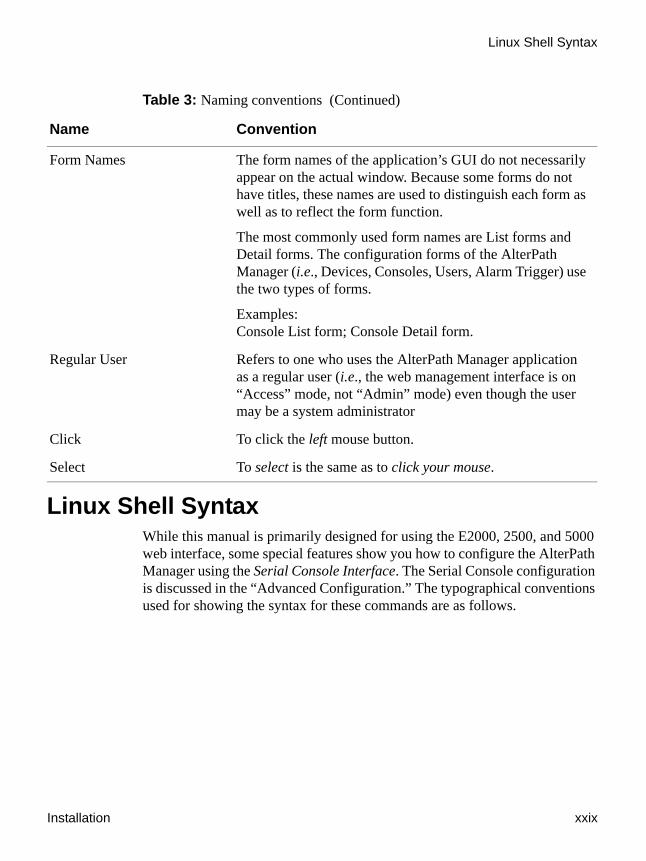
Linux Shell SyntaxWhile this manual is primarily designed for using the E2000, 2500, and 5000 web interface, some special features show you how to configure the AlterPath Manager using the Serial Console Interface. The Serial Console configuration is discussed in the “Advanced Configuration.” The typographical conventions used for showing the syntax for these commands are as follows.
Form Names The form names of the application’s GUI do not necessarily appear on the actual window. Because some forms do not have titles, these names are used to distinguish each form as well as to reflect the form function.
The most commonly used form names are List forms and Detail forms. The configuration forms of the AlterPath Manager (i.e., Devices, Consoles, Users, Alarm Trigger) use the two types of forms.
Examples:Console List form; Console Detail form.
Regular User Refers to one who uses the AlterPath Manager application as a regular user (i.e., the web management interface is on “Access” mode, not “Admin” mode) even though the user may be a system administrator
Click To click the left mouse button.
Select To select is the same as to click your mouse.
Table 3: Naming conventions (Continued)
Name Convention

Linux Shell Syntax
xxx AlterPath Manager Installation, Configuration, and User’s Guide
Table 4: Linux Shell Syntax
Typeface Meaning Example
Brackets ([])
Indicate that the parameter inside them is optional. The command will still be accepted if the parameter is not defined.
When the text inside the brackets starts with a dash (-) and/or indicates a list of characters, the parameter can be one of the letters listed within the brackets.
iptables [-ADC] chain rule-specification [options]
Ellipses (...) Indicate that the latest parameter can be repeated as many times as needed. Usually this is used to describe a list of subjects.
ls [OPTION]... [FILE]...
Vertical Line, or Pipe (|)
One of the parameters separated by this character should be used in the command.
netstat {--statistics|-s} [--tcp|-t] [--udp|-u] [--raw|-w]
<text> Text enclosed in greater than or less than symbols (or angle brackets) is variable text that is to be substituted in a specific command line.
add user <username>

Installation xxxi
Additional Resources
Additional ResourcesCyclades Technical Training Available
Cyclades offers a suite of technical courses to increase your knowledge of the AlterPath Manager.
• AlterPath Manager I: Accessing and Monitoring Your out-of-band Infrastructure.
• AlterPath Manager II: Configuring and Administering Your out-of-band infrastructure.
To learn more about Cyclades Technical Training Center and offerings, please visit our website at http://www.cyclades.com/training, call us at 1-888-292-5233, or send an email to [email protected].
Cyclades Firmware UpgradesCyclades offers periodic firmware upgrades for the AlterPath Manager E2000, AlterPath Manager 2500, and the AlterPath manager 5000. These upgrades are available free of charge to current Cyclades customers. Visit http://www.cyclades.com/support/downloads.php to download the latest firmware. See “To Upgrade the APM Firmware” on page 320 for instructions on upgrading the firmware on your AlterPath Manager.
Spacing and Separators
Lists will not normally have spaces between the items, but will have commas, hyphens, or semicolons as separators.
jane:1,2;john:3,4. The format of this field is:
[<username>:<outlet_list>][;<username>:<outlet_list>...]
Where <outlet_list>'s format is:
[<outlet_number>|<outlet_start>-<outlet_end>][,<outlet_number>|<outlet_start>-<outlet_end>]...
Table 4: Linux Shell Syntax (Continued)
Typeface Meaning Example

Additional Resources
xxxii AlterPath Manager Installation, Configuration, and User’s Guide
Cyclades Technical SupportCyclades offers free technical support. To find out how to contact the support center in your region, go to: http://www.cyclades.com/support/technical_support.php.

The AlterPath Manager E2000, 2500, and 5000 are a family of feature-rich, out-of-band (OOB) managers designed to provide out-of-band infrastructure (OOBI) users and administrators a centralized and convenient way to remotely access target devices and perform all their system fault management work from a single user interface.
Through an easy and convenient web user interface, the regular user of the APM E2000, APM 2500, and APM 5000 can easily view and access consoles, view consolidated logs and reports, and respond to triggers, alarms, and other system issues that may arise.
Through the same web interface (in Admin Mode) or through CLI, the system administrator can configure and manage the APM and all its users from a single location without having to work directly on a target device or server console.
Note: Anyone who uses the APM application in Access mode is referred to as a user, regardless of whether that user is a system administrator or not. An administrator is anyone who has the exclusive authority to configure and administer the APM and its users.
Connectivity and CapacityThe E2000 allows you to configure 2048 devices, 4096 console ports and maintain 256 Data Logging Sessions (DLS) or simultaneous connections to consoles and devices. You can perform firmware upgrades on 256 separate console management devices. The E2000 supports up to 256 simultaneously connected users, and it allows multi-user access to each port.
Figure 1-1: APM E2000, Front View
The port connections, power connection, and power switch of the E2000 are shown in Figure 1-2.
Chapter 1Introduction

Connectivity and Capacity
2 AlterPath Manager Installation, Configuration, and User’s Guide
Caution: On the APM hardware, Eth0 is labeled “Eth1,” and Eth1 is labeled as “Eth2.”
Figure 1-2: APM E2000, Back View
The AlterPath 2500 and 5000 each have a base DLS or simultaneous connection capacity of 64. This can be upgraded to up to 512 DLS connections for an AlterPath 2500 and up to 2048 DLS connections for an AlterPath 5000. The APM 2500 and the APM 5000 are also available with additional DLS connection capacity at the time of initial purchase. For details about DLS capacity, refer to Appendix C, “DLS Activation.”
The LCD control panel, power on/reset, and power off buttons are shown in Figure 1-3.
Figure 1-3: APM 2500, Front View
The port connections, power switch and power connector of the APM 2500 are shown in Figure 1-4.
Expansion slots Eth1 Eth0
USB port 2
USB port 1 AUX serial port
ResetConsole port
FanAC
connector
Powerswitch
LCD panel
Press and hold for 1 second to power on the system.Press and hold for 4 seconds to reset the system.
Press and hold for 10 seconds to shut down the system.
Installation 3
Key Features
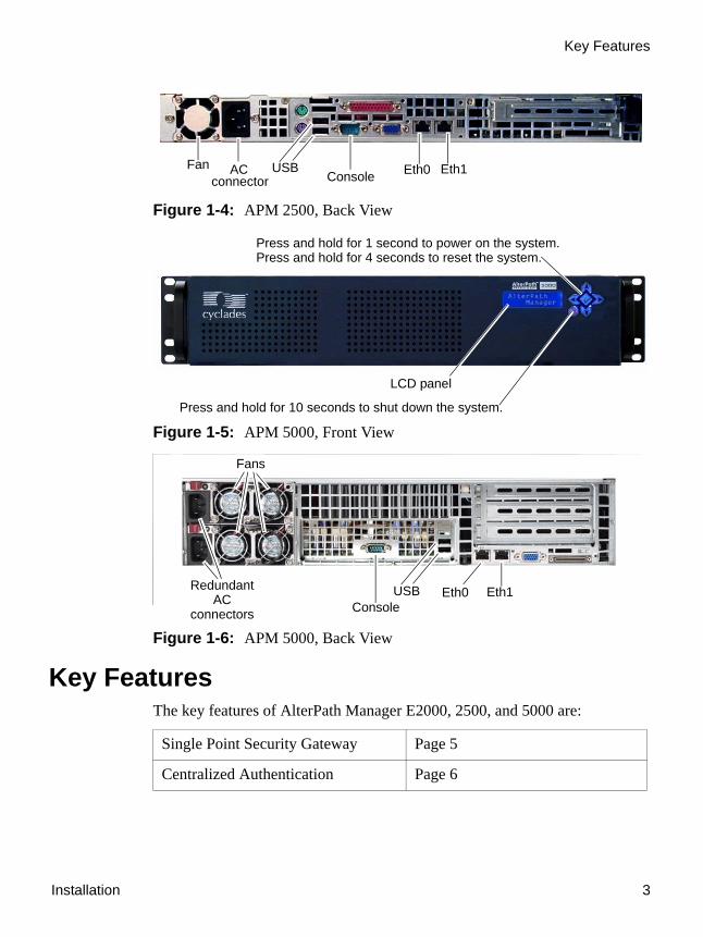
Figure 1-4: APM 2500, Back View
Figure 1-5: APM 5000, Front View
Figure 1-6: APM 5000, Back View
Key FeaturesThe key features of AlterPath Manager E2000, 2500, and 5000 are:
Single Point Security Gateway Page 5
Centralized Authentication Page 6
Fanconnector
AC USB Eth0 Eth1Console
Press and hold for 1 second to power on the system.Press and hold for 4 seconds to reset the system.
LCD panel
Press and hold for 10 seconds to shut down the system.
USBConsole
Eth0 Eth1RedundantAC
connectors
Fans

Key Features
4 AlterPath Manager Installation, Configuration, and User’s Guide
Consolidated Views and Console Access
Page 6
Access Control List (ACL) for Devices
Page 6
Centralized Data Logging System Page 7
Log File Compression and Rotation Page 8
Other Alarm Features Page 8
Modem Support for Remote Sites Page 8
Dial Back Support for ACS Page 9
One Time Password support for ACS Page 9
Multiport Ethernet Page 10
Enhanced Ethernet Port Configuration
Page 10
Ethernet Bonding Page 10
DHCP Option for APM Network Setup
Page 11
Health Monitoring Page 11
Console Wizard Page 11
Device Discovery Page 12
Support for KVM/net Page 12
Support for KVM/net Plus Page 12
KVM/net FW Upgrade Support Page 13
Support for OnSite Page 13
Support for IPMI Page 13
Device, Console, and User Group Management
Page 14

Installation 5
Key Features
Single Point Security GatewayThe AlterPath Manager has been designed such that communication between users and the management network must pass through a single point of access (the AlterPath Manager) to optimize security and enforce adherence to your corporate security policy.
A single, secure access point reduces management overhead for managing console servers. The multiple authentication options available ensure compatibility with existing infrastructure.
Java based appGATE™ MindTerm™ V3.0.1 SW version 1.4.1 will run either the APPGate MindTerm V3.0.1 terminal applet or the MindTerm Java Web Start (JWS). Cyclades supports this terminal applet with Java V1.3 or later with Webstart. This allows customization of the terminal emulator features such as font size, and background and font colors in addition to the usual terminal controls that have been available with the previous terminal emulator.
Blade Module Page 14
Backup, Restore, and Replicate User Data
Page 14
Change and Configuration Management
Page 14
Exhaustive Reporting Page 15
Simple and Easy Web User Interface Page 15
Fault Tolerant Configuration Support
Page 15
Command Line Interface (CLI) Page 16
Interoperability, Integration, and Compatibility
Page 16
Power Management Support Page 17

Key Features
6 AlterPath Manager Installation, Configuration, and User’s Guide
Caution: When running the APM WMI on a browser on a Linux workstation, you must install Java V1.5.0-2 or greater to run the MindTerm terminal applet or the MindTerm JWS.
Note: You can refer to Sun Microsystems’ website, http://java.sun.com/products/javawebstart and click on the “Code Samples & Apps” link. You can also refer to IBM’s Java Web Start website, http://www-128.ibm.com/developerworks/java/library/j-webstart for specifics on implementation of JWS.
You can download the latest Java version from the Java website:http://www.java.com.
Centralized AuthenticationCentralized authentication saves you or the administrator from using a password for each device (e.g., TS, ACS, KVM/net), and thereby maintain a secure password. You need only use your password once upon logging onto the AlterPath Manager. For all users who access the console ports, the AlterPath Manager provides the following authentication methods: local database, RADIUS, TACACS+, LDAP, Kerberos, NIS, and Active Directory.
Consolidated Views and Console AccessFrom the AlterPath Manager web interface, you can view a list of all consoles to which you have authorized access. Information about each console includes console name, port, location, description, and status.
The Access Control List (ACL), which is defined by the administrator, defines which user has access to which port. For added security, users cannot view consoles which they are not authorized to use.
Access Control List (ACL) for DevicesUsers have access to consoles; administrators have access to consoles and console devices.
Device access for regular users is a feature that is new, beginning with Software Version 1.4.0.

Installation 7
Key Features
Regular users can have access control of devices as well as access control of consoles, at the discretion of the AlterPath Manager admin.
A regular user can have access to one or more devices as well as to one or more consoles, if that user has been granted such access by the admin in the user’s access control list. The regular user will never have admin mode access.
An admin profile user (a regular user granted administrative profile rights) can have access (regular user mode access or admin access) to one or more devices as well as to one or more consoles, if that user has been granted such access by the administrator in the user’s access control list. In addition, when the admin profile user creates a device, the admin profile user also has access to all the device’s consoles.
If the Blade Module is enabled, the Console List form also shows the console name for each supported blade server. Right-clicking a console name, enables the user to select KVM, VM, or CLI or to power on or power off, based on the user’s access rights defined in the Security Rule.
Centralized Data Logging SystemThe APM E2000/2500/5000 captures all console log messages and writes them to its internal hard disk drive. This provides a secure and permanent storage of important console log information. Data logging will work with permanently connected devices on Console Servers, Terminal Servers, and OnSite serial ports.
The console log capacity is 20GB, which is about 80MB for each of the APM E2000’s 256 maximum possible concurrent data logging sessions. The secure online/offline storage ensures availability of all important console messages.
The APM 2500 and APM 5000 have a base Data Logging Session (DLS) capacity of 64. This capacity can be expanded (through a DLS feature activation option from Cyclades) to up to 512 DLSs for the APM 2500 and up to 2048 DLSs for the APM 5000. The APM 2500 and the APM 5000 are also available at the time of purchase, with additional, installable DLS activation.
Each line of the logfile contains a timestamp, a feature which prevents tampering and provides a tool for analysis and audit trail tracking. Each time you or any user connects to a DLS enabled port, the APM adds a timestamp to the log file. The user identification timestamp is recorded in the data buffer and logged separately on the APM access log database.
Key Features
8 AlterPath Manager Installation, Configuration, and User’s Guide
Log File Compression and RotationThe system logger automatically saves the current log file after a certain point in time, and then creates a new file to collect a new set of console data. The file rotation is seamless with no data loss as the system copies from one file to another.
The administrator has the option to move the saved log file(s) to another server for archiving.
Prioritized Triggers & Alarms
Note: Alarm triggers work only with serial and IPMI consoles.
The APM E2000/2500/5000 event handling feature enables the system to identify possible issues and alert the user. As the APM sends a message to the hard disk for storing and consolidation, it also scans the message for triggers. A trigger is a text string pre-defined by the administrator which the system uses to detect a trigger text from messages. When the APM detects a trigger text, based on how the trigger was configured by the administrator, it will do the following:
• Send an email to a user list• Create a prioritized alarm entry in the Alarm database• Write a log message to the AlterPath Manager logging system to
acknowledge the trigger.
Other Alarm FeaturesNotes - Allows you to add notes to an alarm to indicate what action you have taken. These notes can be useful for future reference to similar issues.
Reports - Allows you to generate a report to show what actions were taken by whom, and how long it took to fix the issue.
Modem Support for Remote SitesUsing point-to-point protocol (PPP), the AlterPath Manager E2000, 2500, and 5000 are equipped with modem dialing capability to allow complete out-of-band access to remote console server devices. Moreover, users have the

Installation 9
Key Features
choice to use PPP as the primary mode of connection or only as a backup connection in the event that the network fails. The following modem/serial cards are supported:
• Eicon DS series V90 4P analog modem card - North America (does not fit in the E2000)
• Eicon DS series ISDN BRI-2M - International• Perle V90-Modem• Perle multi-port serial• Cyclades 8Yo serial card (supported in E2000 only)
Note: Implementation of an ISDN modem on the APM is the same as with a standard modem but the ISDN modem dials and connects much faster.
Dial Back Support for ACSThe AlterPath Manager E2000, 2500, and 5000 provide options for integrated modems to automatically dial to remote locations when the network fails. In the absence of network connectivity, the dial back feature enables the AlterPath Manager to initiate a call to a remote AlterPath ACS unit, and then have the ACS dial back the connection using a predefined number.
One Time Password support for ACSThe One Time Password (OTP) support in the AlterPath Manager E2000, 2500, and 5000 enables One Time Password authentication when the APM connects to an ACS via modem.The OTP authentication method uses passwords, each of which are only valid once. The one time passwords are calculated by means of a secret passphrase which is encrypted and stored in the APM database. The OTP method of authentication prevents passwords from being intercepted over a phone line and reused, even if the phone line is tapped.
OTP authentication during dialup is transparent to the user (the user does not notice the authentication).

Key Features
10 AlterPath Manager Installation, Configuration, and User’s Guide
Note: The OTP option does not appear when an ISDN modem is being configured.
Multiport EthernetThe AlterPath Manager E2000, 2500, and 5000 supports multiport PCI Ethernet cards for secure networks that use multiple network segments. This enables the AlterPath Manager to physically separate devices and connect to multiple network segments.
The Ethernet cards are detected by the configuration wizard during boot time.
The Ethernet hardware has commands to control the link speed and duplexing supported on each interface.
Enhanced Ethernet Port ConfigurationThere is a script called “setethernet” that is invoked automatically along with the other initial APM configuration the first time the APM is run.The setethernet script can also be run by the administrator manually from the console at any time.
The setethernet script allows the configuration of the Ethernet interface. The following parameters can be set:
• Auto-negotiation mode• 10MBps full duplex• 10MBps half duplex• 100MBps full duplex• 100MBps half duplex• 1000MBps full duplex• 1000MBps half duplex
Ethernet BondingEthernet bonding is a method of providing redundancy to an Ethernet connection. When Ethernet bonding is enabled, the primary Ethernet port operates under normal circumstances. If the primary Ethernet port fails, a backup (or redundant) Ethernet port takes over. This is called a failover

Installation 11
Key Features
condition (e.g., the primary Ethernet port fails over to the secondary Ethernet port). A different interface becomes active if, and only if the active interface fails. After a failover has occurred, the primary interface becomes active once again after the failover condition has been corrected.
DHCP Option for APM Network SetupWhen you configure the network, either through the First Time Configuration Wizard, or through the CLI “setnetwork” command, you now have the option to use DHCP (Dynamic Host Configuration Protocol) to configure Eth0. DHCP allows the APM to obtain its own IP address from the DNS server. If there is no DNS server, or if the DNS server cannot be accessed, the default IP address of 192.168.1.20 will be assigned to Eth0. Eth0 is the only Ethernet port that can be configured to use DHCP. Of course, as always, you can configure Eth0 with a static IP address, if you wish.
Health MonitoringThis feature allows the AlterPath Manager to monitor on a periodic basis the consoles that are running on specified device, to generate log files, and to send an alarm notifications to specified users.
Health Monitoring is designed to ensure that in the event of a network failure, remote sites are available and working properly.
An integral part of Health Monitoring is the Health Modem feature which monitors any modems that are being used to connect to a device either as a primary connection or as a backup. Like Health Monitoring, this feature has its own alarm trigger which the administrator can configure to generate log files and send alarm notifications to users.
Console WizardThe console wizard allows you to define the consoles connected to a device by automatically defining the consoles using default and customized values. The wizard configures the selected console(s) and applies them to the device. The console wizard is designed to work with all types of devices, including KVM/net units and secondary units that are connected to the KVM/net units.

Key Features
12 AlterPath Manager Installation, Configuration, and User’s Guide
Device DiscoveryThe Device Discovery feature enables the AlterPath Manager to recognize the current configuration of a Cyclades TS, ACS, or KVM/net and, through the use of a wizard, auto populate the console parameters based on the values used by the Cyclades TS, ACS, or KVM/net.
For users who already have TS/ACS and/or KVM/net units deployed in their network, Device Discovery eradicates the time-consuming task of re-defining each console port manually.
Support for KVM/netAmong other console types, the AlterPath Manager supports viewing of Keyboard-Video-Mouse-based consoles through the use of an AlterPath KVM/net installed in the network. The user connects through a client software over an IP connection and the KVM/net switch routes the application to one of its ports to connect the user application to the KVM ports of a target server.
The KVM/net supports physical cascading of units to provide more ports. The admin user configures the cascading through the AlterPath Manager.
The KVN/net version 2.0.0 and above features the capability to connect to RDP servers via an in band connection. The RDP capability can be configured and controlled from the APM.
Note: AlterPath Manager is compatible with AlterPath KVM/net version 1.1.0 and above.
Support for KVM/net PlusThe APM supports the KVM/net Plus. The KVM/net Plus supports all the features of the KVM/net. Additionally, the KVM/net Plus features a web control page that replaces the OSD for KVM over IP sessions. The KVN/net Plus also features the capability to connect to RDP servers via an in band connection. The RDP capability can be configured and controlled from the APM.

Installation 13
Key Features
KVM/net FW Upgrade SupportStarting with Version 1.4.0, the AlterPath Manager supports firmware upgrades for the KVM/net. The upgrade facility provides system compatibility checks, copies the firmware, checks the validity of the copy, and reboots the system. The firmware package incorporates KVM/net firmware, KVM over IP module firmware, boot code, microcode for the KVM switch, microcode for the terminators, and microcode for the KVM RP.
Support for OnSiteThe AlterPath OnSite is a compact device that has serial console ports like an ACS and KVM ports like a KVM/net. The AlterPath Manager supports viewing of ACS-based consoles as well as Keyboard-Video-Mouse-based consoles through the use of an AlterPath OnSite installed in the network.
Support for IPMIThe AlterPath Manager supports servers that are based on IPMI (Intelligent Platform Management Interface), the open standard for machine health and control (including remote control). IPMI defines common interfaces to the “intelligent” hardware that is used to monitor server physical health characteristics, such as temperature, voltage, fans, power supplies and more.
These monitoring capabilities provide AlterPath Manager users information that allow power control of servers, recovery, and asset tracking.
The AlterPath Manager allows multiple, concurrent IPMI CLI (Command Line Interface) sessions. The number of sessions allowed matches the number of DLSs activated (see “Centralized Data Logging System” on page 7).
Note: IPMI is a paid-for option for AlterPath Manager users. The feature is enabled only for users who have purchased the option.
Support for HP OpenView NNMWith the optional HP OpenView NNM Integration, the administrator can access remote systems using both in-band and out of band techniques from a common HP OpenView network node manager (NNM) view.

Key Features
14 AlterPath Manager Installation, Configuration, and User’s Guide
Device, Console, and User Group ManagementDevices, consoles, and users can be grouped to further simplify the organization and management of these system components. The administrator may create, update and delete any of the groups at anytime through the web management interface. Users can view only those groups to which they belong or have access.
Blade ModuleThe AlterPath Manager supports blade management (that is, the IBM Blade Center) through the plugged-in Blade Module. Blade configuration and management is available through the web interface or CLI. The Blade Module, once enabled, supports the number of chassis equal to the number of DLS activations installed on your APM—up to 2048 chassis and up to 32768 blades/switches—just like any device or console.
Using the Blade Wizard, an admin user can create 14 blades and 4 switches. All blades provide authorized users with CLI, KVM/IP, virtual media, and power options. For security, Blade users are controlled by the Access Control List (ACL) which is configured through the Security Rule option of the web interface.
Note: The Blade Management Module is a paid-for option for AlterPath Manager users, and is hidden from users who do not need it.
Backup, Restore, and Replicate User DataThis feature allows users to create a backup of the AlterPath Manager configuration, data, and log files. The backup includes data from the compact flash, configuration data from the database, and log data from the console buffer files. This feature also enables users to copy console log files to a server for further analysis and archiving.
Change and Configuration ManagementChange and Configuration Management feature of the AlterPath Manager is designed such that any number of change management procedures can be
Installation 15
Key Features
configured through the AlterPath Manager rather than through the target devices or software.
• Initializing new console servers• Setting the serial ports• Upgrading firmware
All change management configuration is performed by the administrator.
Exhaustive ReportingBecause the AlterPath Manager consolidates all its logs and maintains its own databases, it provides in-depth reporting capabilities to suit the reporting needs of users and managers.
Fault Tolerant Configuration SupportHeartbeat, Redundancy, Data Synchronization, and Failover support provides a means to set up a fault tolerant APM configuration. A fault tolerant configuration has the ability to automatically back up and restore an APM 2500 or APM 5000 system with little or no downtime in the event of a failure of a primary APM.
By using the heartbeat protocol in conjunction with network RAID or RSYNC, a redundant APM automatically takes over control of the managed devices in the event of a failure of the primary APM or its Ethernet connection. After the initial problem with the primary APM is corrected, the redundant APM fails back to the primary APM. After the failback between both APMs is complete, the primary APM resumes control of the managed devices.
Simple and Easy Web User InterfaceThe AlterPath Manager provides a convenient and user-friendly web user interface for the regular user and the administrator. Hyperlinks enable you to access consoles, view data logs, and other information even faster. From one single interface, you can achieve just about everything you need to manage your network’s consoles.

Key Features
16 AlterPath Manager Installation, Configuration, and User’s Guide
As a user you can only view and access those consoles you are assigned. This customization adds security to the system since users cannot view or access any console that does not concern them.
Command Line Interface (CLI)For emergency access situations, the AlterPath Manager can provide you with a command line interface by making a regular Secure Shell connection to the AlterPath Manager.
CLI is one of two user interfaces (the other is the web interface) available to AlterPath Manager users. The CLI is also used for First Time Configuration and system recovery procedures.
Interoperability, Integration, and CompatibilityAPM E2000, 2500, and 5000 Database Compatibility
Each AlterPath Manager model can migrate, backup, and restore its database to or from any other AlterPath Manager model.
Interoperability with Routers and Ethernet SwitchesThe built-in Ethernet ports on the AlterPath 2500 and AlterPath 5000 fully compatible with the following leading manufacturer’s routers and Ethernet switches:
• Cisco®• Juniper®• Nortel®The following features are supported by the built-in Ethernet ports:
• 10/100 Base T Ethernet full and half duplex• Gigabit Ethernet full and half duplex• Autosensing• Fully compatible configurability
• 10/100/1000 Megabit auto sense• Fixed 10 Megabit• Fixed 100 Megabit
Installation 17
Key Features
• Fixed 1000 Megabit (Gigabit)
Note: Gigabit Ethernet is available on the APM 2500 and APM 5000 only.
Interoperability with Cyclades DevicesThe APM firmware 1.4.1 interoperates with the latest versions of the AlterPath Console Server, the AlterPath KVM/net, the AlterPath KVM/net+, the AlterPath Terminal Server, and the AlterPath OnSite.
Interoperability and Compatibility with Modem VendorsThe AlterPath Manager E2000’s serial port(s) work with the following external modem manufacturers’ products that provide encryption within the modem setup process:
• Hayes™• Motorola®• US Robotics®The AlterPath Manager supports dial out and dial back capability through the following:
• PCI modem• built-in serial card (required to connect external modems supporting
encryption)
Note: The APM 2500 and the APM 5000 do not have AUX ports, but they support modem card adapters and serial card adapters.
Power Management SupportThe AlterPath Manager supports AlterPath Power Management (PM) devices that are connected to devices managed by the APM.This feature allows you to create new Intelligent Power Distribution Units (IPDUs) and manage IPDUs through the APM. The APM also allows you to control the outlets of any IPDU and associate IPDU outlets with specific consoles on a device managed by the APM.

KVM/net Support
18 AlterPath Manager Installation, Configuration, and User’s Guide
KVM/net SupportThe AlterPath KVM/net is a Cyclades stand-alone networking device similar in concept to a console server. The user connects through a program over an IP connection and the KVM/net switch routes the application to one of its ports to connect directly to the keyboard, video, and mouse ports of a target server. In the network, you can install a KVM/net with 16 or 32 KVM ports (i.e., AlterPath KVM/net 16 or AlterPath KVM/net 32).
Typical Configuration of AlterPath Manager and KVM
The configuration below shows the AlterPath Manager managing four KVM switches. Two KVM/net switches are accessed directly through IP. The other two are physically cascaded to KVM/net 2. KVM analog switches (as well as KVM Expanders) are normally used as cascaded units since they cost less than KVM/net switches.
Figure 1-7: Configuration Example of APM and KVM/net
Each secondary KVM switch may have one or two connections to a primary KVM/net switch while a primary KVM/net switch may have one or more secondary switches connected.
AlterPath Manager
KVM/net 1 KVM/net 2
KVM Analog KVM Analog
Server Server Server Server Server Server Server Server Server
Ethernet

Installation 19
OnSite Support
In the diagram, if KVM/net 2 is a 16-port device and the two analog switches are also 16-port devices, then KVM/net 2 will have 44 ports available to the user; 32 ports from the two analog switches and 12 ports from KVM/net 2. The four ports in KVM/net 2 are used to connect to the slave units.
Regular users only see the ports to which they can connect. Authentication, authorization, and access accounting (logging) function in the same manner as they do for serial console ports. Health Monitoring consists of periodic checking as defined in the Device Detail form. It will connect to the KVM/net interface and login to the unit to ensure that the IP is valid, including the username and password. Errors are reported by email to the admin user, and an alarm generated.
AlterPath Manager Features Unsupported by KVM/net
When using the KVM/net, logs are available only for access to KVM consoles. The Logs form defaults to Access Logs, and Event Logs. Data Buffering is inactive.
Alarms are generated only for KVM/net Health Monitoring events. The Alarm list form is the same as for serial console alarms, but without the data buffer link.
OnSite SupportThe AlterPath Manager supports the AlterPath OnSite. The OnSite is a single, compact, and powerful AlterPath product that has both serial and KVM ports. The OnSite can be accessed through a terminal, through the ethernet, through a modem, or through your AlterPath Manager.
The AlterPath Manager allows you serial port console access to any computer whose serial port is connected to and configured on an associated OnSite. The AlterPath Manager also allows you KVM port access to any computer whose KVM port is connected to and configured on an associated OnSite. The AlterPath Manager can even provide both types of access to a single computer if both types of access are configured on the associated OnSite.

OnSite Support
20 AlterPath Manager Installation, Configuration, and User’s Guide
Example Configuration of an APM and an OnSiteThe following configuration diagram shows an example of an APM connected to an OnSite with KVM servers and console servers. One server can be accessed through both types of connection.
Figure 1-8: Example of an OnSite accessed by an APM
AlterPath Manager
OnSite
Server
Server
Server
Server
Server
Server
Server
KVM PortsSerial Ports
Ethernet

This section discusses the procedures and requirements for installing the AlterPath Manager E2000, 2500, and 5000. The section is organized as follows:
Product Installation ChecklistYour AlterPath Manager E2000, 2500, or 5000 is shipped with the components as described by the following table:
Product Installation Checklist Page 21
Rack Mounting the AlterPath Manager
Page 24
Deploying the AlterPath Manager Page 26
Safety Considerations When Rack Mounting
Page 28
Pre-Configuration Requirements Page 30
IPMI and Blade Module Options Page 39
Check Item Part Number
Description Purpose
PAC0226 Documentation CD CD with complete documentation for all AlterPath Manager models, as well as documentation for other products that can be used with the APM
Chapter 2AlterPath Manager Installation

Product Installation Checklist
22 AlterPath Manager Installation, Configuration, and User’s Guide
PAC0381 Quick Start Guide A quick installation and configuration guide to get you started with your APM right away
See below for country-specific part numbers.
Power cable Main power cable for AlterPath Manager E2000, 2500, and 5000
CAB0010 Power cable, USA
CAB0037 Power cable, Europe
CAB0056 Power cable, UK
CAB0055 Power cable, Australia
CAB0278 Power cable, Japan
Check Item Part Number
Description Purpose

Installation 23
Product Installation Checklist
CAB0036 Cable, crossover DB-9 female to RJ-45 6 ft.
Can be used with AUX port, ACS and TS serial ports.
HAR0550 Mounting Kit
Mounting brackets, necessary screws for APM E2000
Hardware for rack mounting the AlterPath Manager E2000.
HAR0017
HAR0018
Mounting rail kit
Mounting brackets, screws for APM 2500
Hardware for rack mounting the AlterPath Manager 2500.
Note: The APM 2500 is furnished with the mounting brackets (ears) already attached to it.
HAR0021 Mounting rail kit Hardware for rack mounting the AlterPath Manager 5000.
CAB0041 Cable, 4-foot DB-9 female to DB-9 female null modem cable for APM E2000
Cable for connection from the APM console port to a serial terminal
CAB0286 Cable, 6-foot DB-9 female to DB-9 female null modem, for APM 2500 and APM 5000
Cable for connection from the APM console port to a serial terminal
Check Item Part Number
Description Purpose

Rack Mounting the AlterPath Manager
24 AlterPath Manager Installation, Configuration, and User’s Guide
Rack Mounting the AlterPath ManagerFor the AlterPath Manager E2000, 2500 and 5000, two brackets and the necessary mounting screws are supplied. For the AlterPath Manager 2500 and 5000, a set of sliding rails are also provided (the small “ear” brackets are already attached).
To Bracket Mount an APM1. Attach the mounting brackets to the sides of the APM E2000 towards the
front of the box. Use a screwdriver to firmly tighten the mounting brackets (already attached to the APM 2500 and APM 5000).
2. Mount the APM securely to the vertical bars of the rack. Screws should go in through the front of the brackets into the outside front of the vertical bars. Be sure to locate the APM so the brackets line up correctly with the holes. Be sure the right and left brackets are at the same height.
To Rail Mount an APM 2500 or 50001. Remove the inner rails from the rail assemblies. Slide each inner rail out
until it stops. Then depress the exposed locking tab to unlock the inner rail and slide it out the rest of the way.
2. Attach the inner rails to the sides of the APM 2500 or APM 5000. When the inner rails are correctly positioned, the tabs will be to the rear of the APM, and the front three holes in the inner rails will line up with the holes in the sides of the APM.
3. Attach the outer rails to the rack, using the end brackets. Be sure the open end of each outer rail is located towards the front of the rack.
a. The shorter end brackets mount onto the front of the outer rails. Use the two round screw holes in each front end bracket to mount it in a fixed position to its respective outer rail.
b. The longer end brackets mount onto the rear of the outer rails. The long slots in each rear end bracket can be adjusted to fit the bracket and outer rail assembly to the exact length of the rack.
4. Slide the APM 2500 or 5000 into the front of the rack so the inner rails engage into the outer rails.
Installation 25
Rack Mounting the AlterPath Manager
5. Refer to “Safety Considerations When Rack Mounting” on page 28 of this chapter to ensure safety.
6. Plug the power cable into the AlterPath Manager box.
Insert the female end of the black power cable into the power socket on the console server and the three-prong end into a wall outlet.
Note: To help prevent electric shock, plug the AlterPath Manager into a properly grounded power source. The cable is equipped with a 3-prong plug to help ensure proper grounding. Do not use adapter plugs or remove the grounding prong from the cable. If you use an extension cable, use a 3-wire cable with properly grounded plugs.
To Connect the APM Cables1. Connect the console cable.
Connect one end of this cable to the port labeled “Console” on the Alter-Path Manager; and connect the other end to your PC’s available COM port.
2. Install and launch HyperTerminal, Kermit or Minicom if not already installed.
Note: See “To Configure the COM Port Connection and Log In” on page 31.
You can obtain the latest update to HyperTerminal from:
http://www.hilgraeve.com/htpe/download.html
3. Connect Switch or Hub to PC and the AlterPath Manager.
Your workstation and AlterPath Manager must be on the same physical LAN. Connect one RJ-45 cable from the Ethernet (1 or 2) port of the AlterPath Manager to the hub, and another from the hub to the worksta-tion used to manage the servers.

Deploying the AlterPath Manager
26 AlterPath Manager Installation, Configuration, and User’s Guide
Deploying the AlterPath ManagerThere are two typical ways (or topologies) in which the AlterPath Manager can be set up in a network, or among networks.
• Private network• Single network
Private Network TopologyIn a private network topology, one ethernet port connects AlterPath Manager to the management network; the other, to the public network. The management network comprises all fault management equipment (i.e., TS, ACS, KVM/net, OnSite), devices, and infrastructure used to manage the public network. Equipped with its own Ethernet switches, the management network is physically separate from the public network.
Because any AlterPath Manager user who needs to access serial or KVM console ports must pass through the AlterPath Manager, this is the most secure way to deploy the AlterPath Manager (see Figure 2-1).
Single Network TopologyIn a single network topology, the AlterPath Manager is connected to only one network, and the AlterPath Manager management functions are contained in the same network. While it may appear that the workstation has direct access to the TS and ACS boxes, if users attempt to access them, they will be denied because the AlterPath Manager is already controlling access to the ports. In a single network configuration, a Virtual Local Area Network (VLAN) configuration is recommended (see Figure 2-2).
Caution: When referring to the connection diagrams below, Eth0 and Eth1 are marked as Eth1 and Eth2 respectively on the actual hardware. When configuring the software, be sure to configure these as Eth0 and Eth1. Refer to the rear view illustrations in the “Introduction” section.

Installation 27
Deploying the AlterPath Manager
Private Network DiagramThe diagram below depicts how the AlterPath Manager AlterPath Manager may be set up in a private network structure.
Figure 2-1: Private Network Diagram
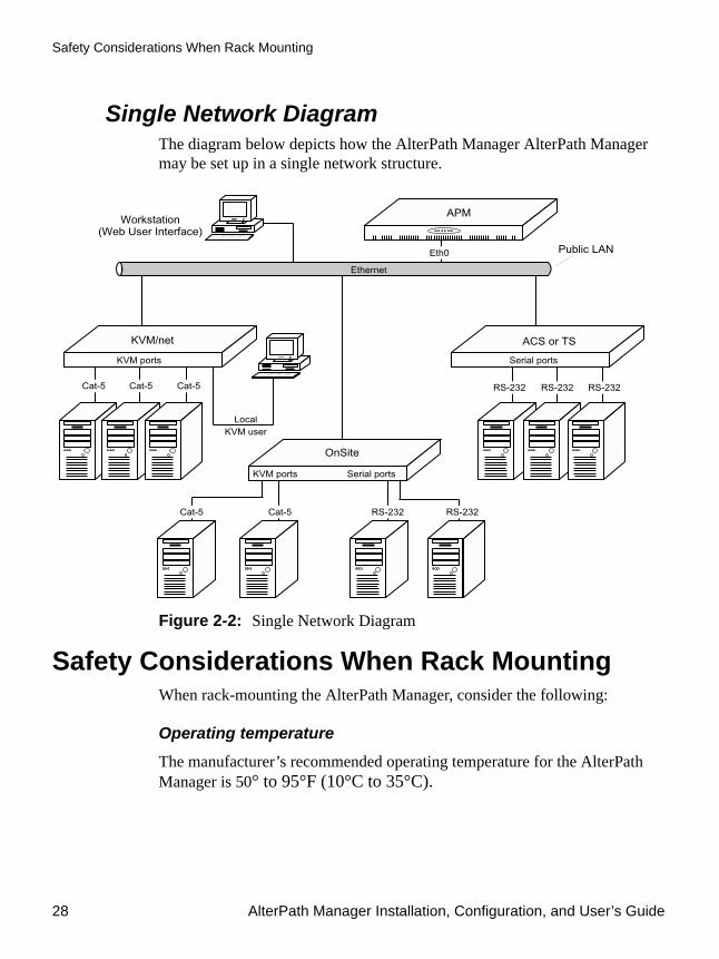
Safety Considerations When Rack Mounting
28 AlterPath Manager Installation, Configuration, and User’s Guide
Single Network DiagramThe diagram below depicts how the AlterPath Manager AlterPath Manager may be set up in a single network structure.
Figure 2-2: Single Network Diagram
Safety Considerations When Rack MountingWhen rack-mounting the AlterPath Manager, consider the following:
Operating temperature
The manufacturer’s recommended operating temperature for the AlterPath Manager is 50° to 95°F (10°C to 35°C).

Installation 29
Safety Considerations When Rack Mounting
Elevated operating ambient temperature
If you install the AlterPath Manager in a closed or multi-rack assembly, the operating ambient temperature of the rack environment may be greater than the room ambient temperature. Ensure that you install the equipment in an environment compatible with the manufacturer’s maximum rated ambient temperature.
Reduced air flow
Ensure that the amount of airflow required for safe operation is not compromised.
Mechanical loading
Ensure that the equipment is mounted or loaded evenly to prevent a potentially hazardous condition.
Circuit loading
Ensure that the connection of the equipment to the supply circuit and the effect that overloading of circuits might have on overcurrent protection and supply wiring. Check the equipment nameplate ratings to address this concern.
Reliable earthing
Maintain reliable earthing of rack mounted equipment by inspecting supply connections other than direct connections to the branch circuit such as power strips or extension cords.

Pre-Configuration Requirements
30 AlterPath Manager Installation, Configuration, and User’s Guide
Pre-Configuration RequirementsBefore configuring AlterPath Manager, ensure that you have a local system with the following system set up and information ready:
Note: To complete the configuration process, go to “First Time Configuration Wizard” on page 92, in .
Requirement Description
HyperTerminal, Kermit, or Minicom
If you are using a PC, ensure that HyperTerminal is installed on your Windows operating system. If you are using the UNIX operating system, use Kermit or Minicom.
NOTE: You must have root access on your local UNIX machine in order to use the serial port.
IP Addresses Have the IP/Mask addresses of the following ready:
- All console servers
- Gateway
- DNS
Optional addresses:
- NTP
- SMTP (only necessary if alarms feature is being used and is sending e-mail notifications regarding alarm conditions.)
NIC Card Ensure that you have a NIC card installed in your PC to provide an Ethernet port, and allow network access.

Installation 31
Pre-Configuration Requirements
Note: Chapter 3, “User Level Web Access” is designed for regular users who will use or operate the application after the AlterPath Manager administrator has completed the configuration procedures discussed in .
Note: For a list of internet browsers and Cyclades device firmware versions supported by the AlterPath Manager, refer to Appendix A, “Technical Specifications.”
To Configure the COM Port Connection and Log InThe console port is used for the initial configuration (also known as First Time Configuration in this document) which is performed using the Console Interface via serial console connection.
First Time Configuration establishes the superusers for the Console Interface (hardware configuration) and the web interface. AlterPath Manager connectivity and system settings is also set up during First Time Configuration. Configuration through the web interface is discussed in “Configuration and Administration.”
Before using the terminal, make sure it is configured as follows:
1. Select an available COM port.
In HyperTerminal (Start > Program > Accessories > Communications > Hyper Terminal), select File > Properties, and click the “Connect To” tab. Select the available COM port number from the Connection dropdown.
2. Configure COM port.
Click the Configure button.
Your PC, considered here to be a “dumb terminal,” should be configured as follows:
• Serial Speed: 9600 bps• Data Length: 8 bits• Parity: None

Pre-Configuration Requirements
32 AlterPath Manager Installation, Configuration, and User’s Guide
• Stop Bits: 1 stop bit• Flow Control: none• ANSI emulation
3. Power on the AlterPath Manager
4. Click OK on the Properties window.
You will see the AlterPath Manager booting on your screen. After it finishes booting, you should see the configuration screen.
Web Browser RequirementsYou will need a local Windows workstation running a web browser that supports the following:
• ActiveX• Java plug-ins To view KVM console ports on your local Windows workstation, you will need to run a web browser that has ActiveX enabled. Windows browsers that support ActiveX include Microsoft Internet Explorer, and Netscape 7.1 or greater, and Netscape 8.x.
Caution: Microsoft Internet Explorer update version SP2, does not have ActiveX enabled by default. If you update Internet Explorer, or if you implement a new installation of Internet Explorer, you must be sure to enable ActiveX.
Caution: Browsers other than Internet Explorer are known to have a limitation with logins by more than one user from a single workstation. After the initial login session has started, a subsequent login by a different user will force the previous user to be logged out. This occurs either with more than one session with completely separate browser windows, or with more than one session started in tabs within one browser (e.g., Netscape 8.x).
To view serial console ports, you will need to install Java plug-ins. Java plug-ins are located at:
http://www.sun.com

Installation 33
Pre-Configuration Requirements
To Enable ActiveX on Internet Explorer1. Open an Internet Explorer session.
2. Click on Tools > Internet Options > “Security” tab > “Custom Level” button.
3. Make sure you enable the selections shown as enabled in Figure 2-3, “Options to Enable for ActiveX.”
Figure 2-3: Options to Enable for ActiveX

Pre-Configuration Requirements
34 AlterPath Manager Installation, Configuration, and User’s Guide
To Enable ActiveX on Netscape 7.x
Note: This applies to Netscape 7.x where x > 1.
1. Go to the following path, using Windows Explorer:
Note: This path can vary if Netscape 7.x was installed in a directory other than the default.
2. Locate the file named “activex.js” and edit it.
3. In the editor, change the following line from:
to:
4. Save the file and exit the editor.
5. Restart Netscape 7.x
To Enable ActiveX on Netscape 8.x1. Open the Netscape 8.x Browser.
2. On the pull-down menu bar, go to the Tools > Options.
C:\Program Files\Netscape\Netscape\defaults\pref
pref("security.classID.allowByDefault", false);
pref("security.classID.allowByDefault", true);

Installation 35
Pre-Configuration Requirements
Figure 2-4: “Tools” Pull-down menu with “Options” Selected
3. Click on “Options”
An “Options” window appears.

Pre-Configuration Requirements
36 AlterPath Manager Installation, Configuration, and User’s Guide
Figure 2-5: Netscape 8 Options Window
4. Click on “Site Controls” in the left column of the window.
The window that appears has the button to enable ActiveX.

Installation 37
Pre-Configuration Requirements
Figure 2-6: “Site Controls” Option Selection
5. Select “Internet Explorer” in the “Rendering Engine” box in the lower right of the window.
6. Select “Enable ActiveX” in the “Web Features” box.
7. Click the “OK” button.
8. Enter the IP address of your APM in the URL entry field of your Netscape browser.
Notice the shield icon shown in Figure 2-7:

Pre-Configuration Requirements
38 AlterPath Manager Installation, Configuration, and User’s Guide
Figure 2-7: Location of Shield Icon and URL Entry Field
9. Click on the Shield Icon.
A “Trust Settings” dialog box appears.
Shield icon URL entry field

Installation 39
Pre-Configuration Requirements
Figure 2-8: Trust Settings Dialog Box
10. Click on the “I Trust This Site” button.
ActiveX is enabled, and you have marked your APM’s IP address as a trusted site.
IPMI and Blade Module OptionsThe AlterPath Manager can optionally provide the following paid-for features:
• IPMI • Blade Module
You can purchase the IPMI and Blade Module options from your Cyclades sales team, or Cyclades partners.
Cyclades customer service will need the MAC (Ethernet hardware) address of Eth0 (the first Ethernet controller in your APM) to generate the license file which will activate your new features. To find your MAC address, see “Verifying your MAC Address” on page 41

Pre-Configuration Requirements
40 AlterPath Manager Installation, Configuration, and User’s Guide
Verifying your Current IPMI and Blade CapabilityLog on to the Web User Interface and click on the “About” link in the upper left corner of the display. A window that shows IPMI, blade, and any other licenses and their status appears:
Figure 2-9: Feature Window
You can also log on to the CLI (on the serial console port) as root or as admin and run the following command:
# sysinfo
Valid licenses end with the string “VALID=true”
An example screen display follows:

Installation 41
Pre-Configuration Requirements
Verifying your MAC AddressLog on to the CLI (on the serial console port) as root or as admin and run the following Linux system command:
# ifconfig
[root@APM-gregg root]# sysinfoSystem Model : APM e2000Boot Version : 1.0.2 (Sep/10/2002)Kernel Version : 2.6.12.3Config Version : V_1.4.1OS Version : V_1.4.1 (Apr/07/2006)APM Version : V_1.4.1 (04/07/2006)APM Database : V_1.4.1 (2006-02-14)CPU 0 : Celeron (Coppermine) 847.691MHz 1675.26 bogomipsRAM : 516384 kB (282100 kB free)
Licenses
FEATURE= IBMBLADEMODULEName=APM_B_IBMBLADEMODULE, version=1.0.1, type=null, feature=IBMBLADEMODULE, device=APM,owner=paulo, customer_id=gregg,expiry_date=2006-05-28, expiry_time=00:00, info=null, VALID=true
FEATURE= IPMIName=APM_B_IPMI, version=1.0.1, type=null, feature=IPMI, device=APM,owner=paulo, customer_id=gregg,expiry_date=2006-05-28, expiry_time=00:00, info=null, VALID=true
FEATURE= DLSName=APM_B_DLS_256, version=1.0.1, type=standard, feature=DLS, device=APM,owner=Cyclades Corporation, customer_id=cyclades,expiry_date=9999-01-31, expiry_time=00:00, info=e2000 base license, VALID=true
FEATURE= NNMName=APM_B_NNM, version=1.0.1, type=null, feature=NNM, device=APM,owner=paulo, customer_id=gregg,expiry_date=2006-05-28, expiry_time=00:00, info=null, VALID=true

Pre-Configuration Requirements
42 AlterPath Manager Installation, Configuration, and User’s Guide
A display similar to the following will appear:
The numbers following the “HWaddr” subheading for each Ethernet controller installed (eth0 and eth1 by default) is the MAC address for the controller.
To activate the Blade Module1. Log onto your APM through the serial console interface as root.
2. Copy your Blade Module license, using the full path as shown:
/var/apm/licenses/data/APM_B_IBMBLADEMODULE.enc
3. Run the command:
/etc/init.d/tomcat restart
eth0 Link encap:Ethernet HWaddr 00:90:FB:81:57:17 inet addr:192.168.48.162 Bcast:192.168.51.255 Mask:255.255.252.0 UP BROADCAST RUNNING MULTICAST MTU:1500 Metric:1 RX packets:9691587 errors:133 dropped:0 overruns:0 frame:133 TX packets:5726282 errors:0 dropped:0 overruns:0 carrier:0 collisions:1038728 txqueuelen:1000 RX bytes:685270715 (653.5 Mb) TX bytes:548308906 (522.9 Mb) Interrupt:10 Base address:0xc000 Memory:e5020000-e5020038 eth1 Link encap:Ethernet HWaddr 00:90:FB:01:8C:D7 inet addr:10.10.10.2 Bcast:10.10.255.255 Mask:255.255.0.0 UP BROADCAST RUNNING MULTICAST MTU:1500 Metric:1 RX packets:632 errors:0 dropped:0 overruns:0 frame:0 TX packets:622 errors:0 dropped:0 overruns:0 carrier:0 collisions:0 txqueuelen:1000 RX bytes:38288 (37.3 Kb) TX bytes:42288 (41.2 Kb) Interrupt:11 Base address:0xc400 Memory:e5021000-e5021038 lo Link encap:Local Loopback inet addr:127.0.0.1 Mask:255.0.0.0 UP LOOPBACK RUNNING MTU:16436 Metric:1 RX packets:113528 errors:0 dropped:0 overruns:0 frame:0 TX packets:113528 errors:0 dropped:0 overruns:0 carrier:0 collisions:0 txqueuelen:0 RX bytes:15268713 (14.5 Mb) TX bytes:15268713 (14.5 Mb)

The web interface provides two modes for using the AlterPath Manager E2000, 2500, and 5000 based on the type of user: Access (for operation by regular users) and Admin (for configuration by system administrators). “User Level Web Access” explains the procedures for operating the AlterPath Manager web interface in Access mode.
Addressed specifically to regular users, this chapter is organized as follows:
Note: If you are an AlterPath Manager system administrator, refer to Chapter 4, “Chapter 4.”
User Interface OverviewThe AlterPath Manager user interface provides you with four main menu options
Note: With browsers other than Internet Explorer, there are limitations with multiple users accessing the AlterPath Manager via the Web Management Interface on a single workstation. If you plan to have more than one user simultaneously open APM Web access sessions from a single workstation, you should use Internet Explorer.:
User Interface Overview Page 43
Alarms Page 48
Consoles Page 56
Logs Page 68
Power Management Page 73
User’s Profile Page 77
Chapter 3User Level Web Access

User Interface Overview
44 AlterPath Manager Installation, Configuration, and User’s Guide
To Access the APM Web ApplicationTo open the AlterPath Manager web application, perform the following steps:
1. Type in the following URL in your web browser’s URL address field:
https://<nnn.nnn.nnn.nnn>
Table 3-1: User Interface Main Menu
Menu Selection Description
Alarms The Alarms list form is the first form that you see (or the default form) when you log in. Use this form to view alarms, update the status of an alarm or close an alarm after resolving it
Consoles / Devices(select “DEVICE” from the “Filter by” pull-down selector)
List form to view a list of devices assigned to you. From the list, click on the device you wish to access.
For IPMI and Blade Module users, the Consoles List form provides access to the IPMI as a device as well as the chassis blades and switches.
Consoles / Devices(select “CONSOLE” from the “Filter by” pull-down selector)
List form to view a list of consoles assigned to you. From the list, click on the console you wish to access.
For IPMI and Blade Module users, the Consoles List form provides access to the IPMI SOL as well as the chassis blades and switches.
Logs Use the Logs form to view the “Access” logs, “Events” logs, and “Data Buffer” logs for a particular console or device.
User’s Profile The User’s Profile form displays the profile of only the user currently logged in. Use the User Profile to view or modify your own user information, view your own security rule, or change select a new color scheme for your WMI.
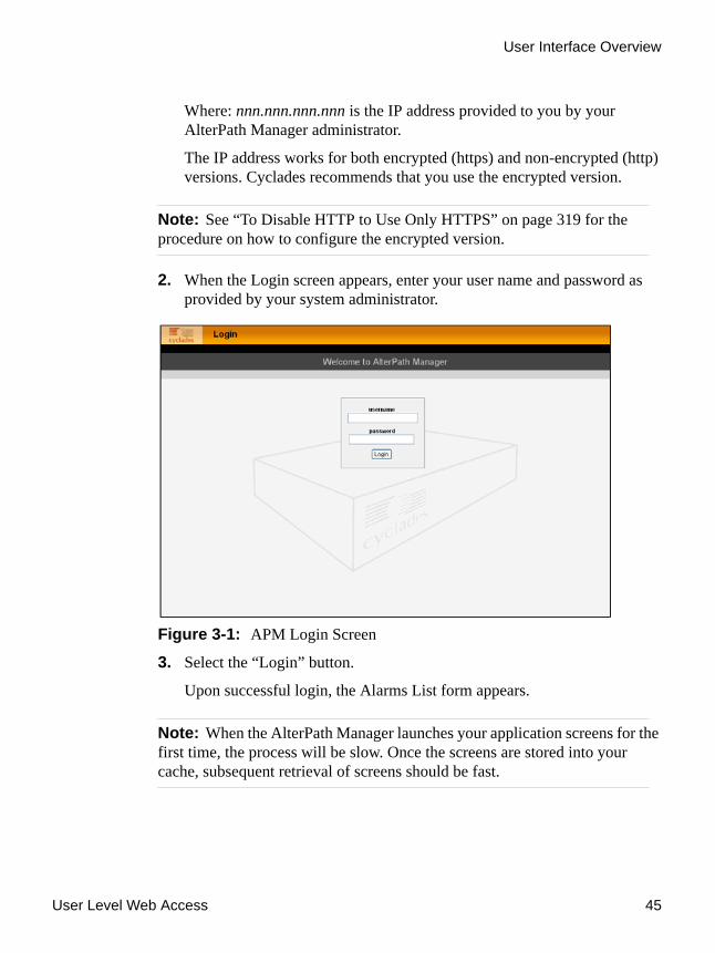
User Level Web Access 45
User Interface Overview
Where: nnn.nnn.nnn.nnn is the IP address provided to you by your AlterPath Manager administrator.
The IP address works for both encrypted (https) and non-encrypted (http) versions. Cyclades recommends that you use the encrypted version.
Note: See “To Disable HTTP to Use Only HTTPS” on page 319 for the procedure on how to configure the encrypted version.
2. When the Login screen appears, enter your user name and password as provided by your system administrator.
Figure 3-1: APM Login Screen
3. Select the “Login” button.
Upon successful login, the Alarms List form appears.
Note: When the AlterPath Manager launches your application screens for the first time, the process will be slow. Once the screens are stored into your cache, subsequent retrieval of screens should be fast.

User Interface Overview
46 AlterPath Manager Installation, Configuration, and User’s Guide
General Screen FeaturesThe diagram below shows the general features of the AlterPath Manager Web Management Interface (WMI). The sample form is for illustration only; it is not the first form that you see when you log in as a regular user.
Figure 3-2: Console / Devices Menu
The menu bar highlights the currently selected menu option.
“Access” tab indicates thatuser interface is for regular users.
“Logout” tabMenu bar showing Consoles/Devices
User view ordata input form
Firmware version info
Panel to manage list
as the selected menu choice
Username and primary IP addressOnline help

User Level Web Access 47
User Interface Overview
Your user name and IP address appears on the upper right hand corner of the screen.
The “Admin” tab (not visible in the example above) is visible only to users with admin rights.
Be sure to select the “Logout” tab on the top right hand corner after you finish your session.
Sorting a List Form by Column/Field NameMost list forms provide sort, search, and filter functions.
An underlined column name indicates that the list can be sorted by the column name. The Console List form, for example, allows you to sort by Console, Type, Device, Location, or Status. To sort by Location, simply click the column name, “Location”.
The arrow adjacent to the heading indicates that the list is sorted based on that heading. The position of the arrowhead indicates the sort order. A downward arrowhead indicates that the list is alphanumerically arranged in ascending order; an upward arrowhead, in descending order. You can change the sort order by clicking on the heading or the arrow.
Search and Filter FunctionsWhen available, you will find the “Filter By” and “Search For” fields at the bottom of a list form.
This allows you to search through a list form by selecting the search category (i.e., Console group) from the dropdown field and selecting and filling in the “Search” field.
The “Search” function has been improved. You can now type the first critical characters of a search string and press “Enter” to view all items in a list that start with those characters. The input field is retained until you click a menu item.
The view generated from the “Filter By” field is automatically saved.

Alarms
48 AlterPath Manager Installation, Configuration, and User’s Guide
Online HelpYou can always find the “help” link in the upper left corner of the WMI (see Figure 3-2) when you are logged in to the WMI. Click on this link to access online help.
AlarmsThe Alarms List form is the default form of the AlterPath Manager Web Interface in “Access” mode. An alarm is a brief message alerting you of a possible problem that requires an action.
When AlterPath Manager detects an alarm, it sends the alarm along with a ticket number to the user’s Alarms List form. As a user, you should see only those alarms assigned to you by your administrator.
If the trigger for the alarm has been configured to send an email, then you should also receive an email notification regarding the alarm. Each alarm or ticket in the list includes a timestamp, a priority level, and a status.
Alarm LogsThe AlterPath Manager not only stores each alarm in a database, but also maintains a log for each alarm. There are two ways in which you can view alarm logs:
• From the Alarms List form • From the Logs form: Logs > (select console) > Event Logs
To Respond to an alarmSince no two issues are exactly the same, you have several ways to respond to an alarm depending on its nature and severity. A typical procedure for responding to an alarm is as follows:
1. Accept the ticket or assignment.
2. Reassign the ticket or assignment to another user, and optionally add notes about the ticket.

User Level Web Access 49
Alarms
Once assigned, the user working on the ticket can perform any of the following procedures to resolve the alarm or complete the ticket:
• View the Console log and other related logs.• Edit information ticket by changing the status and adding notes.• Connect to the console.• Run a console session.• If problem is fixed, change the alarm status and close the ticket.• Re-assign the ticket to another user.
Alarms List FormWhen you first log in to the AlterPath Manager as a regular user or select “Alarms” from the menu, the Alarms List form is the first form that you will see. Use this form to view the list of alarms, to connect to a console, and to view console logs. To re-assign the current ticket, change the ticket status, and add notes or comments, use the “Alarms Detail (or Ticket Info) Form” on page 51.
Figure 3-3: Alarms List Form

Alarms
50 AlterPath Manager Installation, Configuration, and User’s Guide
To View the Alarms Detail FormThe Alarms Detail form contains detailed information about the ticket as generated by an alarm. It allows you to re-assign the ticket, update the status, and enter notes regarding the alarm or ticket.
To view the ticket information for an alarm, follow the steps below:
Table 3-2: Alarms List Form
Element Definition
Ticket Ticket number assigned to an alarm. The symbol above the ticket number indicates the severity level of the alarm. Select the number to display the Alarm Detail form.
Console Console from which the alarm originated. Click on the console name to enable a console session according to the type of configured device and console. For example, a serial console will establish a text-based session; a KVM console will launch the KVM viewer, and an IPMI console will launch the SSH applet and connect to the IPMI SOL console.
Console Config Console configuration. Select this to view the Console Detail form (which includes the secondary form: Console Notify, Console Access, and Console Group) for the particular console record.
Alarm Trigger The Alarm Trigger name. Click on the name to view the Alarm Trigger Detail form.
User Assigned User assigned to the alarm.
Status Status of the alarm.
Console Log Select this to navigate to the Data Buffer log pertaining to the console.
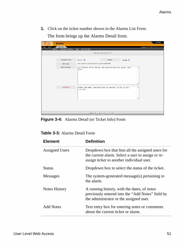
User Level Web Access 51
Alarms
1. Click on the ticket number shown in the Alarms List Form.
The form brings up the Alarms Detail form.
Figure 3-4: Alarms Detail (or Ticket Info) Form
Table 3-3: Alarms Detail Form
Element Definition
Assigned Users Dropdown box that lists all the assigned users for the current alarm. Select a user to assign or re-assign ticket to another individual user.
Status Dropdown box to select the status of the ticket.
Messages The system-generated message(s) pertaining to the alarm.
Notes History A running history, with the dates, of notes previously entered into the “Add Notes” field by the administrator or the assigned user.
Add Notes Text entry box for entering notes or comments about the current ticket or alarm.

Alarms
52 AlterPath Manager Installation, Configuration, and User’s Guide
To View Alarm or Console LogsYou can view the console log for a particular alarm or ticket from the Alarms List form. To view the console log, follow the step below:
1. From the Alarms List form, under the “Console Log” column heading, select the corresponding view link for the console log you wish to view.
The system displays the Logs form:
Figure 3-5: Logs Form
Back Button to return to the Alarms List form.
Save Button to save your entries.
Reset Button to reset the form to its original or default values.
Table 3-3: Alarms Detail Form (Continued)
Element Definition

User Level Web Access 53
Web Access for Users
To Assign or Re-assign a Ticket to a UserTo assign or re-assign a ticket, follow these steps:
1. From the Alarms List form, select an alarm or ticket to open the Alarm Detail or Ticket Information form.
The system opens the Alarms Detail form.
2. From the Ticket Information form, select a user from the “Assigned Users” dropdown list box.
3. If applicable, select the status from the “Status” dropdown list box.
4. If applicable, type in your notes or comments in the “Notes” text entry box.
5. Select “Save” to complete your entry.
Web Access for UsersConsoles/Devices
Users can access consoles and devices when they have been granted permission to do so by the AlterPath Manager admin user.
Devices that can be accessed include:
• ACS• TS• KVM/net• KVM/net+• OnSite
Consoles that can be accessed include:• Serial ports on the ACS, TS, and the OnSite• KVM ports on the KVM/net and OnSite
To Access Consoles or Devices1. Log onto the WMI.
2. Select “Consoles/Devices” from the main menu.
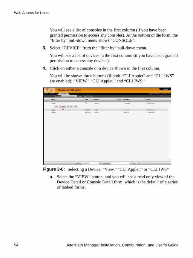
Web Access for Users
54 AlterPath Manager Installation, Configuration, and User’s Guide
You will see a list of consoles in the first column (if you have been granted permission to access any consoles). At the bottom of the form, the “filter by” pull-down menu shows “CONSOLE”.
3. Select “DEVICE” from the “filter by” pull-down menu.
You will see a list of devices in the first column (if you have been granted permission to access any devices).
4. Click on either a console or a device shown in the first column.
You will be shown three buttons (if both “CLI Applet” and “CLI JWS” are enabled): “VIEW,” “CLI Applet,” and “CLI JWS.”
Figure 3-6: Selecting a Device: “View,” “CLI Applet,” or “CLI JWS”
a. Select the “VIEW” button, and you will see a read only view of the Device Detail or Console Detail form, which is the default of a series of tabbed forms.

User Level Web Access 55
Web Access for Users
Figure 3-7: Access Device Detail Form
The tabs include:
• Details• Notify• Groups• Proxies• Dial-Up• Log RotateAll the forms are read only forms.
b. Select the “CLI Applet” button or the “CLI JWS” button, and a CLI viewer will be launched.
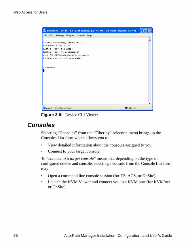
Web Access for Users
56 AlterPath Manager Installation, Configuration, and User’s Guide
Figure 3-8: Device CLI Viewer
ConsolesSelecting “Consoles” from the “Filter by” selection menu brings up the Consoles List form which allows you to:
• View detailed information about the consoles assigned to you.• Connect to your target console.
To “connect to a target console” means that depending on the type of configured device and console, selecting a console from the Console List form may:
• Open a command line console session (for TS, ACS, or OnSite).• Launch the KVM Viewer and connect you to a KVM port (for KVM/net
or OnSite).

User Level Web Access 57
Web Access for Users
Optional Features
For the following paid-for options, the Consoles menu also allows you to:
• Connect to an IPMI Serial Over Lan (SOL) console. • View individual blades and switches of the chassis, as part of the Blade
Module.
Figure 3-9: Consoles List Form
To View Consoles from the ListThe Consoles List form allows you to view the consoles to which you have authorized access.
To view a selected console from the Consoles List form, follow this step:
1. From the Consoles List form, under the “Name” column, click on the console you wish to view.
2. Select the “VIEW” button.

Web Access for Users
58 AlterPath Manager Installation, Configuration, and User’s Guide
Figure 3-10:Selecting a Console to View
A view only version of the “Console Details Form” appears.
To Connect to a ConsoleTo connect to a console:
1. From the Console List form, select the console you wish to connect to by selecting the console name.
Note: If a modem is connected to a remote site, you will experience a slight delay before connecting to a console.
The system normally connects you to a console through Secure Shell (SSH).
In KVM/net, the listed console names are the KVM/net ports. Clicking on the console name provides a “KVM” button which is used to launch the ActiveX application that connects to the port.
If the console name is an IPMI console, clicking on the console name launches an SSH session and connects to the IPMI CLI (Command Line Interface) console.
Regardless of the type of “console,” the AlterPath Manager handles the authentication.

User Level Web Access 59
Web Access for Users
Multiple Users and Read/Write Access Because the AlterPath Manager supports multiple connections to the same port, this makes it possible for multiple users to view the same form. Note, however, that only the first user to connect to that port can have full Read and Write (R/W) access to the Console panel while the rest can have Read only (R) access.
Viewing an IBM Blade Center, Blade, or Switch
Note: This feature is available only to users of the optional Blade Module.
The AlterPath Manager allows you to view individual IBM blade centers from the Devices List form and individual blades and switches from the Consoles List form. To view an IBM blade center, blade, or switch, place the mouse cursor on the device name or the blade/switch name and then left click the mouse to display the list of connect options:.
Like all other consoles, as a regular user, you can only view those blade servers to which you have access. You may also view your user profile with regards to blade access from the “User’s Profile” option of the menu, “Security” form.
Consoles Detail FormUse the Consoles Detail form to view specific information about a particular console. You can invoke this form from either the Alarms List form or the Consoles List form.
If you have admin privileges, you also use this form to select user(s) to notify of the alarm and select user(s) to have access to the current console. The sample forms in this section use a TS console as an example.
Table 3-4: IBM Blade Device and Console Connect Options
Console or Device Connect Options
IBM Blade Center Device VIEW, LOG, CLI, WEB
Blade Console VIEW, CLI, VM, KVM, ON, OFF
Switch VIEW, CLI, WEB, ON, OFF

Web Access for Users
60 AlterPath Manager Installation, Configuration, and User’s Guide
Figure 3-11:Consoles Detail FormTable 3-5: Consoles, Details Form
Element Meaning
Details Tab to display the Console Detail form.
Notify Tab to tell you if you are on the notification list.
Groups Tab to tell you if any groups are assigned to the console.
Outlets Tab to view power management information.
Log Rotate Tab to view log rotation settings
Console Name Name of the (target) console.
Device Name Name of the device used by the console.

User Level Web Access 61
Web Access for Users
Port Drop-down field for selecting the physical port number of the console. For KVM consoles, this field also has an “RDP Only” selection that allows you to configure an RDP port without associating it with a physical KVM port.
Note: RDP only works on KVM/net version 2.0.0 or higher and on KVM/net Plus.
Profile Name User profile type (not in KVM or IPMI console).
Description A brief description of the console.
Machine Type Type of target system.
Machine Name Other applicable system name.
OS Type Operating system used by the console.
OS Version Version of operating system.
Location Physical location of the console.
Status Status of the target console (Enable, Disable, On Demand).
RDP IP Address (KVM consoles only). The field for entering the IP address of the RDP server to be associated with this port. If a physical KVM port is specified in the “Port” field, then an RDP (in band) connection and a regular KVM (out of band) connection can be made to this port.
RDP Server Port This field contains the RDP viewer port number associated with this console. The default of 3389 can be used in most cases.
Table 3-5: Consoles, Details Form (Continued)
Element Meaning

Web Access for Users
62 AlterPath Manager Installation, Configuration, and User’s Guide
Caution: Be sure to turn off your web browser’s popup blocker before attempting to make an RDP connection. An RDP connection will fail if you have your browser’s popup blocker turned on.
To View the Consoles Notify FormThe Consoles Notify form shows the users who are notified when an alarm pertaining to the current console is generated.
To view the Consoles Notify form:
1. From the Consoles Detail form, click on the “Notify” tab.
The system displays the Consoles Notify form:
Figure 3-12:Consoles Notify Form
RDP Status Drop-down field used to enable or disable the ability to make the RDP connection.
Back Button to return to the previous page or form.
Table 3-5: Consoles, Details Form (Continued)
Element Meaning

User Level Web Access 63
Web Access for Users
In the selection box, a plus (+) sign indicates a group, as opposed to a user. USER is the default list which contains all users.
To View the Consoles Groups FormThe Console Groups form shows the group(s) to which the current console belongs.
To view the Consoles Group form:
1. From the Consoles Detail form, click on the “Groups” tab.
The system displays the Consoles Group form:
Figure 3-13: Consoles Group Form
KVM/net Plus Web Control PageThe KVM/net Plus utilizes a web control page that replaces the OSD during KVM over IP sessions. The web control page parameters can be viewed and edited from the APM.
To Access the Web Control Page1. Launch a KVM/net Plus KVM viewer session from the APM.

Web Access for Users
64 AlterPath Manager Installation, Configuration, and User’s Guide
A window indicating that the KVM viewer is launching will pop up. The KVM viewer will be launched momentarily.
Figure 3-14:KVM Viewer Launch Initialization Window
After the KVM viewer appears, the launch window is replaced (in the background) by a console list control window.
2. After the KVM viewer appears, bring the console list control window to the foreground.
3. Click on the console name that corresponds to the console displayed in the KVM viewer window.
Note: Every time a KVM viewer is launched from the APM, a new console is displayed in the console list control window.

User Level Web Access 65
Web Access for Users
Figure 3-15:KVM Console List Control Page
A web control page window similar to the window shown in the following figure appears.

Web Access for Users
66 AlterPath Manager Installation, Configuration, and User’s Guide
Figure 3-16:KVM/net Web Control Page
The web control page allows viewing of the status of the port on which you are connected. It also allows you to:
1. Reset the mouse and keyboard associated with the console you are accessing.
2. Manage outlets associated with the console you are accessing.
3. Configure the video contrast and brightness associated with the console you are accessing.
Note: A similar page will appear when you select the console of a KVM/net, but the parameters can be viewed, but not changed.

User Level Web Access 67
IPMI
IPMIIPMI is a paid-for added feature of AlterPath Manager, which is available only to IPMI users.
To View IPMI SensorsThe IPMI Sensor form is used to view IPMI-based servers. IPMI (Intelligent Platform Management Interface) is the open standard for machine health and control (including remote control). The form allows you to monitor server physical health characteristics, such as temperature, voltage, fans, power supplies and more.
To view IPMI Sensors, perform the following procedure:
1. From the Devices List form, select an IPMI console to view.
2. From the Device Detail form, click on the Sensor button.
The system displays the IPMI Sensors form:
Figure 3-17: IPMI Sensors form

Logs
68 AlterPath Manager Installation, Configuration, and User’s Guide
LogsThe Logs option of the menu allows you to select and view three types of logs pertaining to the console assigned to you:
All three logs are available for the specified console. To access each log, select the appropriate log type from the title bar. As with consoles and alarms, you can only view the logs of systems to which you have authorized access.
When you select Logs from the menu panel, the primary form, shown below, will prompt you for a range of dates from which to retrieve your logs.
Table 3-6: Log Types
Log Type Definition
Access Log Logs that provide logging information (i.e., who accessed the console, when and for how long, etc.) about a particular console.
Events Log Logs that provide information about notifications and alarms (who handled the alarm, what action was taken, etc.) triggered by a particular console.
Data Buffer This is a log of all transaction data generated on the console.

User Level Web Access 69
Logs
Figure 3-18: Log Selection Form
To View the LogsTo view the logs available for a specified console (to which you have authorized access), perform the following steps:
Table 3-7: Log Selection Form
Element Definition
Console/Device Drop down list to select a console or device that will be the basis of the log(s) to be retrieved.
Date From Drop down list to select the starting date of the log(s) to be viewed.
Date To Drop down list to select the end date of the log(s) to be viewed.
Retrieve Button to download the requested log(s) and display the Log forms.

Logs
70 AlterPath Manager Installation, Configuration, and User’s Guide
1. Select “Logs” from the menu.
The system brings up the main Console Logs form.
2. From the Console pop up list, select the console from which you want to view the logs.
Note: You can only view or access the logs of consoles to which you have authorized access.
3. Select a range of dates from which to base your logs by selecting from the “Date from” and “Date to” fields. You can click on the button with the ellipsis (. . .) to view a pop up calendar.
4. Select a range of times from which to base your logs by selecting from the “Time from” and “Time to” pop up lists
The system brings up the Logs Detail form.
Access LogsThe Access Logs (default log browser) provide all access information (e.g., who accessed the console, access date, action taken, etc.) about your target console.
The name of the console/port/device to which the logs apply to is shown below the tab titles.

User Level Web Access 71
Logs
Figure 3-19: Access Logs Form
Event LogsUse the Event Logs browser to view all events that occurred (within a specified range of time) on your target console. Events are triggered by alarm settings.
Table 3-8: Access Logs Form
Element Definition
Date Date in which the event occurred.
Time Time of the event.
User User who connected to the console.
Action What the user did in response to the alarm.
Connection Type of connection (e.g., SSH, Web); IP address used.
Status Status of the console (Success / Fail).

Logs
72 AlterPath Manager Installation, Configuration, and User’s Guide
Figure 3-20: Event Logs Form
Data BufferUse the Data Buffer browser to view the contents of the data buffer generated by a target console.
Table 3-9: Event Logs Form
Element Definition
Date Date of the event.
Time Time of the event.
Ticket Ticket number associated with the event.
Pattern Alarm trigger name associated with the event.
Action Action taken to resolve event.

User Level Web Access 73
Power Management
Figure 3-21: Data Buffer Log Form
Note: You can also access the Data Buffer log from the Alarms form.
Power ManagementIf you have been given access to one or more power management devices by your system administrator, you will be able to access some of the PM control functions.
The following figure shows an example of a user PM device detail form.

Power Management
74 AlterPath Manager Installation, Configuration, and User’s Guide
Figure 3-22:PM Device Viewer Detail FormTable 3-10: IPDU Viewer Details
Element Definition
Details Opening tab that is the default when you edit a power management device.
Groups Tab that opens the PM device groups access form for viewing
IPDUs Info Tab that opens a display of data read back from the PM device after you click on the “Get Information” button.
Outlets Tab that opens the outlets control form. From here, you can select individual outlets, regardless of whether or not they are assigned to a KVM port, and turn them on or off, cycle them, or lock or unlock them, either individually, or in selected groups. You can also view the current status of each outlet from this form after clicking on the “Get Information” button.
Log Rotate Tab that opens the Log Rotation settings form for viewing.

User Level Web Access 75
Power Management
Device Name A name you can give to the PM device to help you remember where it is and what it controls.
Type Fixed at “IPDU”
Vendor Fixed at Cyclades
Model The model and output current capacity of the PM device.
Connection A pull-down list allowing you to select either “ssh,” “ssh_telnet,” or “telnet.”
Status A pull-down list allowing you to select either “On Demand” (to enable the PM) or “Disabled.”
Connected to: The name of the controlling device (KVM/net, OnSite, ACS, or TS) to which the PM device is connected.
Port This is either port “1” (or an incremented number for each cascaded device) on a KVM/net or OnSite, or the serial port number of an ACS or a TS to which the PM device is connected.
Alarm threshold If set to 0, the alarm will occur when default current threshold of the PM is exceeded. You can set this to an alternate threshold below the default threshold, if you wish.
Over current protection
If selected, automatically shuts off an outlet if the current at that outlet exceeds the current limit.
Buzzer If selected, sounds a buzzer if the alarm threshold is exceeded.
Syslog If selected, allows PM device alarm events to be logged.
Back Button that allows you to go back to the previous form without saving any configuration parameters.
Table 3-10: IPDU Viewer Details (Continued)
Element Definition

Power Management
76 AlterPath Manager Installation, Configuration, and User’s Guide
To View PM Device Parameters1. Select “Access” tab > “Consoles/Devices” > “Devices” pull-down list.
2. Click on the PM device that you wish to view or edit.
You will see a “VIEW” button and a “CLI” button appear just below the device name.
3. Click the “VIEW” button.
The “Editing IPDUs Device” (PM device details) form appears.
Note: The editable PM device parameters will be greyed out when this form is first displayed.
4. If you want to view any parameters on the “Details,” “Groups,” “IPDUs,” or “Outlets” control/status forms, click on the “Get Information” button at the bottom of any of the “Editing IPDUs Device” forms.
Note: None of these parameters can be changed and saved by a regular user, but outlet status can be changed between on, off, or toggle; or between locked and unlocked. This is done from the PM Device Outlet Control Form
Get Information This button is used to update information displayed in the “IPDUs Info” and the “Outlets” forms, since they are not updated in real time.
Table 3-10: IPDU Viewer Details (Continued)
Element Definition

User Level Web Access 77
User’s Profile
Figure 3-23:PM Device Outlet Control Form
For any outlet to which you have access, you can power on, power off, toggle, lock, or unlock. After you check the appropriate box(es), click on the “Execute Operations” button.
User’s ProfileThe User’s Profile forms allow you to view your profile or contact information and modify a limited number of fields. The system allows you to view only your own profile.
Note: The Administrator can view all user profiles.

User’s Profile
78 AlterPath Manager Installation, Configuration, and User’s Guide
Figure 3-24: User’s Profile Details Form
The Admin user’s profile details form is slightly different from that of the regular user. Notice the “Security Rule” check box.
Figure 3-25:Admin User’s Profile Details Form

User Level Web Access 79
User’s Profile
Table 3-11: User’s Profile Details Form
Element Definition
Details Default tab displays the User’s Profile Detail form (currently displayed).
Preferences Tab displays functions such as CLI timeout, CLI running mode, and GUI theme.
Consoles ACL Consoles access control list (ACL) for the current user. Tab displays the selected consoles assigned to the current user and the consoles accessed by the user through group association.
Devices ACL Devices access control list (ACL) for the current user. Tab displays the selected devices assigned to the current user and the devices accessed by the user through group association.
Groups Tab to display the User’s Profile Group form which shows all groups to which the current user belongs.
Security Tab to display the security rule or rules assigned to the current user. The built in security rules are “DEFAULT RULE” and “ADMIN RULE.”
User Name The user name used to log into the AlterPath Manager.
Admin User If “YES,” indicates that the user has Admin privileges, and also belongs to the Admin user group.

User’s Profile
80 AlterPath Manager Installation, Configuration, and User’s Guide
Security Rule
See the Admin User’s Profile Details Form.
(For Admin use only)
Check box to indicate that a security rule has been assigned to the user. Designed to prevent admin users from locking themselves out, the check box is available only to admin users.
NOTE: In case the admin user is locked out when this check box is selected, the admin user can edit the script file:/var/apm/bin/apm_unlock_admin.sh from the Linux shell through the Serial Console Interface.
Local Password Check box to indicate that local authentication applies to the user. If this box is checked, the “Set Password” button becomes active.
Set Password Button that launches a password setup dialog box.
Full Name User’s full name.
Email User’s email. This is the same field name used by the system for event notification.
Department User’s department.
Location User’s Location.
Phone User’s phone number.
Mobile User’s mobile phone number.
Pager User’s pager number.
Status Indicates whether the user’s access is enabled or disabled.
Save Button to save the user’s configuration changes.
Table 3-11: User’s Profile Details Form (Continued)
Element Definition
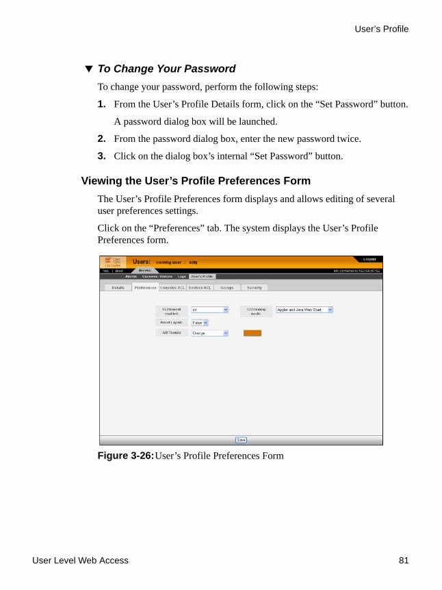
User Level Web Access 81
User’s Profile
To Change Your PasswordTo change your password, perform the following steps:
1. From the User’s Profile Details form, click on the “Set Password” button.
A password dialog box will be launched.
2. From the password dialog box, enter the new password twice.
3. Click on the dialog box’s internal “Set Password” button.
Viewing the User’s Profile Preferences FormThe User’s Profile Preferences form displays and allows editing of several user preferences settings.
Click on the “Preferences” tab. The system displays the User’s Profile Preferences form.
Figure 3-26:User’s Profile Preferences Form

User’s Profile
82 AlterPath Manager Installation, Configuration, and User’s Guide
Viewing the User’s Profile Consoles ACL FormThe User’s Profile Consoles ACL form displays the Consoles to which you have access.
Click on the “Consoles ACL” tab. The system displays the User’s Profile Consoles form:
Table 3-12: User’s Profile Preferences Form
Element Definitions
CLI timeout enabled Select “on” or “off” for this field. When “on” is selected, any MindTerm CLI terminal emulator launched by the user will terminate when the user logs off the WMI.
CLI running mode Provides the choice of “Applet only,” “Java Web Start only,” or “Applet and Java Web Start.” This gives the user the option of how the CLI terminal emulator is started.
Note: The “Java Web Start” terminal emulator is dynamic when changing some settings, such as font size and columns and widths. The applet option opens the terminal emulator a little faster.
Reset Layout If you set this to “True,” it will reset the CLI applet and Java Web Start terminal emulator parameters to the default settings upon clicking the “Save” button.
Note: This field is always set to “False” when you open the User’s Profile Preferences form.
GUI Theme This provides a choice of four color themes (blue, gray, green, or orange) that appear when the user logs into the WMI. There is also a “custom” selection, which gives the user the ability to create customized colors based on pallets or hexadecimal values for RGB settings.
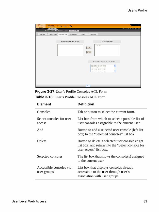
User Level Web Access 83
User’s Profile
Figure 3-27:User’s Profile Consoles ACL FormTable 3-13: User’s Profile Consoles ACL Form
Element Definition
Consoles Tab or button to select the current form.
Select consoles for user access
List box from which to select a possible list of user consoles assignable to the current user.
Add Button to add a selected user console (left list box) to the “Selected consoles” list box.
Delete Button to delete a selected user console (right list box) and return it to the “Select console for user access” list box.
Selected consoles The list box that shows the console(s) assigned to the current user.
Accessible consoles via user groups
List box that displays consoles already accessible to the user through user’s association with user groups.

User’s Profile
84 AlterPath Manager Installation, Configuration, and User’s Guide
Viewing the User’s Profile Devices ACL FormThe User’s Profile Devices form displays the groups to which you belong.
To view the User’s Profile Devices form:
Figure 3-28:User’s Profile Devices ACL FormTable 3-14: User’s Profile Devices ACL Form
Element Definition
Devices Tab or button to select the current form.
Select devices for user access
List box from which to select a possible list of user devices assignable to the current user.
Add Button to add a selected user device (left list box) to the “Selected devices” list box.
Delete Button to delete a selected user device (right list box) and return it to the “Select device for user access” list box.
Selected devices The list box that shows the device(s) assigned to the current user.

User Level Web Access 85
User’s Profile
Viewing the User’s Profile Groups FormThe User’s Profile Groups form displays the groups to which you belong.
To view the User’s Profile Groups form:
From the User’s Profile Detail form, click on the “Groups” tab. The system displays the User’s Profile Groups form:
Figure 3-29: User’s Profile Groups Form
Accessible devices via user groups
List box that displays devices already accessible to the user through the user’s association with user groups.
Table 3-15: User’s Profile Groups Form
Element Definition
Groups Tab or button to select the current form.
Table 3-14: User’s Profile Devices ACL Form (Continued)
Element Definition

User’s Profile
86 AlterPath Manager Installation, Configuration, and User’s Guide
Viewing the User’s Profile Security FormThe Security form shows the current security rule assigned to you (as well as any other rules to which you have access). A security rule defines a user’s access control to a device as well as through which user group that rule is assigned.
For Blade Module users, the Security Rule includes access to blades and switches.
To view the Security form:
From the menu, select: “User’s Profile” > “Details” form > “Security” tab. The system displays the User’s Profile Security form:
Select groups for the user List box from which to select a possible list of user groups assignable to the current user.
Add Button to add a selected user group (left list box) to the “Selected groups” list box.
Delete Button to delete a selected user group (right list box) and return it to the “Select groups for the user” list box.
Selected Groups The list box that shows the group(s) assigned to the current user.
Table 3-15: User’s Profile Groups Form (Continued)
Element Definition

User Level Web Access 87
User’s Profile
Figure 3-30: User’s Profile Security FormTable 3-16: User’s Profile Security Form
Element Definition
Security Tab or button to select the current form.
Select security rules List box from which to select a possible list of security rules assigned to the current user.
Add Button to add a selected security rule (left list box) to the “Selected security rule” list box.
Delete Button to delete a selected security rule (right list box) and return it to the “Select security rule” list box.
Selected security rules The list box that shows the Security Rule assigned to the current user.
Security rules via user groups
The list box that shows the security rules already assigned to a user through the user’s association with user groups.

User’s Profile
88 AlterPath Manager Installation, Configuration, and User’s Guide

This chapter presents the procedures for configuring the AlterPath Manager through the Web Management Interface (WMI). Addressed to the E2000, 2500, and 5000 administrator who must use the AlterPath Manager web interface in Admin Mode, the chapter is organized as follows:
Operational Modes Page 90
First Time Configuration Wizard Page 92
AlterPath Manager Web Interface: Admin Mode Page 103
Relocating Online Help Page 106
Devices Page 110
Proxies Page 121
Dial Up and Dial Back Page 127
Alarm Trigger Page 169
Profiles Page 178
Consoles Page 181
Users Page 199
Groups Page 210
Firmware Page 215
Backing Up User Data Page 221
System Recovery Guidelines Page 222
Info / Reporting Page 223
Blade Management Module Page 225
Security Rules Page 245
Power Management Support Page 256
Redundant (Fault Tolerant) Configuration Page 261
Chapter 4Configuration and Administration

Operational Modes
90 AlterPath Manager Installation, Configuration, and User’s Guide
Operational ModesThe AlterPath Manager provides two operating modes for configuration:
• First Time Configuration (Linux shell on the serial console)• Admin Mode (GUI-based)
Before you can use the AlterPath Manager Web Management Interface (WMI) you must first run the First Time Configuration wizard.
The admin user, by default, is the system administrator of the AlterPath Manager web interface and runs the application in Admin mode. This designation cannot be revoked. Unless a regular user has been configured to be an admin user as well (through the User Detail form), regular users can use the application only in Access mode.
Only an administrator or admin user can use the WMI in Admin Mode which allows them to assign admin roles to new users; to add users, consoles, devices (console servers) alarms, and other configuration procedures.
Note: For information on how to use the system in Access mode, refer to Chapter 3, “User Level Web Access” on page 43.
Note: Certain configuration procedures (e.g., System Recovery, Modem Card Configuration) require the use of the Linux shell on the serial console by advanced users. These procedures are discussed in Chapter 5, “Advanced Configuration” on page 277.

Configuration and Administration 91
Configuration Process Flow
Configuration Process Flow
Figure 4-1: AlterPath Manager Configuration Process Flow
DevicesConsolesUsers GroupsAlarm
Trigger Profiles FirmwareSecurity
RulesInfo/
Reporting Jobs
Details
Password
Security
Manual
ConsolesACL
DevicesACL
Groups
Security
Details
UsersACL
Notify
Groups
Outlets
LogRotate
Details
Details Details
Details Details
List List
UsersACL
Notify
Groups
Proxies
KVMViewer
Dial Up
LogRotate
ConsoleGroup
DeviceGroup
UserGroup
Releasenotes
Connect toserial console
Perform First TimeConfiguration
Wasreboot
successful?
Log on to AlterPathManager WMI as “admin”
Reset system to defaultfactory settings
2
31 2
3
44
No
Yes
55
1

First Time Configuration Wizard
92 AlterPath Manager Installation, Configuration, and User’s Guide
You must perform the First Time Configuration process (as shown in the “AlterPath Manager Configuration Process Flow” chart) using the Linux shell through the serial console interface. Once completed, you may perform the rest of the configuration process and all daily administration procedures through the AlterPath Manager web interface.
To configure all your devices with the AlterPath Manager (using the web interface), you must first configure the devices such as console servers or a KVM switch (menu options: “Devices” and “Profiles”), and then configure the consoles or ports associated with the devices (menu option: “Consoles”).
The “Firmware” option is used to update firmware and to enable you to select from different versions of firmware, or to view information about a particular firmware.
Once you have configured the consoles, you can define users and assign them to access the target consoles (menu option: “Users”), and define the triggers that will create alarms and send email notifications (menu option: “Alarm Trigger”) to users.
First Time Configuration WizardBefore you run First Time Configuration, check to ensure that your system is set up properly. If you are using a PC, ensure that HyperTerminal is installed on your Windows operating system. If you are using the UNIX operating system, use Kermit or Minicom.
Ensure that you have a NIC card installed in your PC to provide an Ethernet port, and allow network access.
Refer to Chapter 2, “AlterPath Manager Installation” for procedures on how to prepare for First Time Configuration.
The first time configuration process is designed to:
• Establish user as root, the superuser for the serial console interface.• Establish user as Admin, the superuser for the AlterPath Manager web
user interface and the command line interface (CLI).• Initialize your system and user settings to ensure full connectivity and
functionality of the AlterPath Manager.

Configuration and Administration 93
First Time Configuration Wizard
First Time Configuration requires that you:
• Connect to the serial console• Log in as “root”.
To Use the First Time Configuration Wizard1. Before you power on the AlterPath Manager, connect one end of a DB-9
to DB-9 Null Modem cable (or equivalent) to the console port of the AlterPath Manager.
2. Connect the other end of the cable to a terminal or a computer’s serial port.
3. Using the terminal or a terminal emulation program installed on a computer, start a session with the following settings:
• 9600 BPS
• 8 data bits
• No parity
• 1 stop bit
• ANSI emulation
4. Power on the APM
Boot information will scroll up on the screen for a short time until the system is ready for initial configuration input data.
5. Press any key to run the First Time Configuration Wizard.
You will be asked to enter the following parameters:
• Enter a password for root (and re type the password)
Welcome to Cyclades-APM! Since this is the first time you are booting your APM, you need to answer some basic configuration questions. Once this is done, the other APM configuration parameters can be set through its Web Management Interface (WMI). Press any key to continue.

First Time Configuration Wizard
94 AlterPath Manager Installation, Configuration, and User’s Guide
• Enter a password for admin (and re type the password)
• Select a time zone
• Enter a new system date and time (format is MM/DD/YY)
Note: You must type a date, even if it is the same as the date displayed, in order to change the time.
• Enter the time (if you did not select the default date: format is HH:MM)
• Select (Y)es or (N)o for Enable Ethernet Bonding. (see example on Page 100 for no and example on Page 301 for yes).
• Select (S)tatic, (D)HCP, (N)one, or (K)eep for the Ethernet 0 (eth0) IP address
• Enter the eth0 IP address (if you selected static)
Note: When you are connecting to a public network (see Figure 2-2, “Single Network Diagram” on Page 28), Eth0 can be configured with 2 IP addresses as long as both addresses conform to the subnet and address range of the public LAN.
• Enter the eth0 subnet mask address
• Select (S)tatic, (N)one, or (K)eep for the eth1 IP address
• Enter the eth1 IP address (if you selected static)
Note: When you are connecting to a private network (see Figure 2-1, “Private Network Diagram” on Page 27), Eth0 (the primary Ethernet port) is connected to the public LAN. The Eth0 address and subnet must conform to the public LAN’s subnet and address range. Eth1 (the secondary Ethernet port) is connected to the private LAN with its own subnet and address range.
• Enter the secondary Ethernet subnet mask address
• Configure Ethernet subinterfaces (Y)es, (N)o, or (L)ist
• Configure Ethernet VLANs (Y)es, (N)o, or (L)ist

Configuration and Administration 95
First Time Configuration Wizard
• Enter Ethernet default gateway
• Set Ethernet eth0 speed/duplex
• Choose the correct operation mode from the following:
1) Auto-negotiation2) 10 Mbps, full duplex3) 10 Mbps, half duplex4) 100 Mbps, full duplex5) 100 Mbps, half duplex6) 1000 Mbps, full duplex7) 1000 Mbps, half duplex
Note: 1000 MBps speed Ethernet is available on the APM 2500 and APM 5000 only.
• Set Ethernet eth1 speed/duplex
• Enter the system's hostname (max 30 characters)
• Enter the system's domain name (max 60 chars)
• Enter the primary nameserver's IP address
• Enter the secondary nameserver's IP address
• Enter the NTP server
• Enter the E-mail (SMTP) server
• Enter an authentication method (local, RADIUS, TACACS+, LDAP, Kerberos, NIS, Active Directory)
Note: After you select an authentication service type, you will be prompted with questions that are specific to that type of authentication. For example, if you select RADIUS, you will be prompted for the RADIUS server name and the RADIUS secret.
Once you have finished with the last parameter, the configuration will automatically be saved to flash memory.

First Time Configuration Wizard
96 AlterPath Manager Installation, Configuration, and User’s Guide
To Change Individual Parameters
Note: If you make changes to any of the foregoing configuration steps, you can adjust most configuration parameters by running one of the following commands as required.
1. Choose the appropriate command from the list below:
• setauth
• setboot
• setdatetime
• setdhcp
• setethernet
• sethosts
• setnames
• setnetwork
• setntp
• setserial
• setsmtp
• date
When you are finished updating any of the configurations that use the preceding commands, enter the command: saveconf
More detailed information on the preceding commands is available under “Set Commands” on page 286.
To Reset Configuration to Factory SettingsIf you wish, you can reset the configuration to its factory default settings and start over. To reset the configuration, follow these steps:
1. Log in to the management console as root.
2. Type in: defconf and press Enter.

Configuration and Administration 97
First Time Configuration Wizard
3. Type in: reboot and press Enter.
An Example follows:
Refer to the sample First Time Configuration Wizard example in the following section, to view how the parameters are entered into the system.
First Time Configuration Wizard: An ExampleThe First Time Configuration sample session shown below shows the portion of the command line data where the user configuration begins. This is commenced by the heading, “Welcome to Cyclades-APM!”
Before the Welcome heading appears, the system will prompt you for the following:
Caution: Be sure you answer “n” to the following questions.
APM_gregg login: rootPassword: *************************************************************************** WARNING: changing system files directly is dangerous and may adversely ** affect your system's functionality. Proceed with caution, and ** only if you know what you are doing! *************************************************************************** [root@APM_gregg root]# defconf WARNING: this will erase all of your current configuration and restore the system's factory default configuration. This action is irreversible! Are you sure you wish to continue? (y/N) yRestoring default configuration ... done.The new configuration will take effect after the next boot.[root@APM_gregg root]# reboot

First Time Configuration Wizard
98 AlterPath Manager Installation, Configuration, and User’s Guide
Note: In the following examples, items shown in bold type represent user input.:
The screen scrolls to the “Welcome” heading.
Press any key to get to the password entry prompts.
Note: Passwords are not displayed on the console screen when they are typed.
Do you want to re-create hard disk partitions? (y/n)[n] Do you want to re-create the System file system? (y/n)[n] Do you want to re-create the Console Log file system? (y/n)[n] Do you want to re-create the Configuration file system? (y/n)[n]
Welcome to Cyclades-APM! Since this is the first time you are booting your APM, you need toanswer some basic configuration questions. Once this is done, theother APM configuration parameters can be set through its WebManagement Interface (WMI). Press any key to continue.
You must now set a password for 'root', the system administrative account.WARNING: this is a very powerful account, and as such it's advisable that its password is chosen with care and kept within the reach of system administrators only.New password:Re-enter new password:Password changed You must now set a password for 'admin', the administrative account for theWeb Management Interface (WMI).WARNING: this is a very powerful account, and as such it's advisable that its password is chosen with care and kept within the reach of system administrators only.New password:Re-enter new password:Password changed

Configuration and Administration 99
First Time Configuration Wizard
After configuring your root and admin passwords, you are prompted to enter your time zone.
Please choose the time zone where this machine is located. 1) Africa 18) Eire 35) Jamaica 52) ROC 2) America 19) Etc 36) Japan 53) ROK 3) Antarctica 20) Europe 37) Kwajalein 54) Singapore 4) Arctic 21) Factory 38) Libya 55) SystemV 5) Asia 22) GB 39) MET 56) Turkey 6) Atlantic 23) GB-Eire 40) MST 57) UCT 7) Australia 24) GMT 41) MST7MDT 58) US 8) Brazil 25) GMT+0 42) Mexico 59) UTC 9) CET 26) GMT-0 43) Mideast 60) Universal10) CST6CDT 27) GMT0 44) NZ 61) W-SU11) Canada 28) Greenwich 45) NZ-CHAT 62) WET12) Chile 29) HST 46) Navajo 63) Zulu13) Cuba 30) Hongkong 47) PRC 64) iso3166.tab14) EET 31) Iceland 48) PST8PDT 65) posix15) EST 32) Indian 49) Pacific 66) posixrules16) EST5EDT 33) Iran 50) Poland 67) right17) Egypt 34) Israel 51) Portugal 68) zone.tabEnter the number corresponding to your choice: 48

First Time Configuration Wizard
100 AlterPath Manager Installation, Configuration, and User’s Guide
Since this is the first time you are booting your APM, you need to configure the date, the time, the Ethernet settings, and the authentication protocol.
At this point, the First Time Configuration Wizard has completed its job. Some system and configuration status messages scroll up the screen until the “login” prompt appears.
Setting the Authentication MethodThe sample First Time Configuration selects local as the Authentication Method to use to authenticate a user.
Current system date and time is: Fri Apr 07 08:21:56 PDT 2006Press ENTER to accept it or specify new ones.Enter date in MM/DD/YYYY format: 04/07/2006Enter time in HH:MM format: 15:23Fri Apr 07 15:23:00 PDT 2006Enable Ethernet Bonding: (Y)es or (N)o ? [N]: nEthernet eth0 IP address: (S)tatic, (D)HCP or (N)one ? [S]: sEnter Ethernet eth0 IP address: 192.168.48.162Enter Ethernet eth0 Subnet Mask: 255.255.252.0Ethernet eth1 IP address: (S)tatic or (N)one ? [S]: sEnter Ethernet eth1 IP address: 10.10.10.2Enter Ethernet eth1 Subnet Mask: 255.255.255.0Configure Ethernet Subinterfaces: (Y)es, (N)o or (L)ist ? [N]: nConfigure Ethernet VLANs: (Y)es, (N)o or (L)ist ? [N]: nEnter Ethernet Default Gateway [none]: 192.168.48.1Current Ethernet eth0 speed/duplex settings: AUTOChange Ethernet eth0 speed/duplex: (Y)es or (N)o ? [N]: nCurrent Ethernet eth1 speed/duplex settings: AUTOChange Ethernet eth1 speed/duplex: (Y)es or (N)o ? [N]: nEnter the System's Hostname (max 30 characters) [APM]: APM-greggEnter the System's Domain Name (max 60 chars) [localdomain]: cyclades.comEnter the Primary Nameserver's IP address [none]: 192.168.44.21Enter the Secondary Nameserver's IP address [none]:Enter the NTP server:Enter the email (SMTP) server: smtp.cyclades.comChoose the desirable authentication method (local/radius/tacacs+/ldap/kerberos/nis/active_directory) [local]:Saving configuration files to flash (/flash/config/config.tgz)... done.Removing init_config flag... done.

Configuration and Administration 101
First Time Configuration Wizard
Depending on the type of authentication service that you select, the wizard will prompt for questions relating to the authentication service of your choice. For example, if you select RADIUS, the system will prompt you for the RADIUS server name and the secret. Selecting TACACS+ will prompt you for the TACACS+ server IP address, the shared secret, and the available service (system).
If you select NIS, the system will prompt you for the NIS Domain Name and the NIS Server. For the NIS Domain Name, the system will accept localdomain, or you may leave the field blank.
Note: If you use NIS Authentication and the NIS server fails, APM will not allow you to add the user in the local database since it already exists in the NIS server. This is due to the way NIS centralizes and distributes user account information into common local files. For more detailed information, refer to the “NIS Configuration” on page 311. For more details refer to the “AlterPath Manager Installation, Configuration, and User’s Guide.”
Configuring Active DirectoryTo use Active Directory as your authentication method, select active_directory. See “To Configure Active Directory” on page 316.
Limitation of TACACS Plus in ACS Console AccessBeware that access to an ACS console through the AlterPath Manager is currently not possible if the ACS serial port is configured to use TACACS Plus authentication.

First Time Configuration Wizard
102 AlterPath Manager Installation, Configuration, and User’s Guide
Hostname Configuration Must Follow RFC StandardWhen configuring the hostname, the name must comply with RFC 608 which states that the hostname is a string composed of:
• Up to 48 characters• Alphabetical (A-Z)• Digits (0-9), and the minus sign (-) • No blank or space characters allowed• No distinction between upper and lower case letters• First character is a letter• Last character is not a minus sign
Any deviation from this standard may cause the web browser to disable APM cookies and prevent the user from logging into the AlterPath Manager web application.
Multiport Ethernet Card ConfigurationThe AlterPath Manager supports up to two multiport Ethernet cards to allow connection to network segments. The First Time Configuration Wizard will detect any multiport Ethernet card that is installed in the AlterPath Manager and will prompt you for network information. If you are using this feature, be ready to provide the network IP addresses.
Note: To configure Ethernet speed and duplex settings, go to “setethernet - Set Ethernet Speed and Duplexing” on page 290.
Once the First Time Configuration is complete, you may connect to the web interface to begin web configuration.
To Begin Web Configuration1. Type the URL in the one of the following formats in your web browser
• non-encrypted:http://nnn.nnn.nnn.nnn
• encrypted.https://nnn.nnn.nnn.nnn

Configuration and Administration 103
AlterPath Manager Web Interface: Admin Mode
Where: nnn.nnn.nnn.nnn is the IP address of either the first or second Ethernet interface that you defined during the First Time Configuration.
2. When the Login screen appears, enter “admin” as the username and then enter the admin password (as specified during the First Time Configuration).
The admin user is by default the manager of the AlterPath Manager web interface and runs the application in admin mode. This designation cannot be revoked.
Disabling HTTP to Use Only HTTPSThe AlterPath Manager is configured to allow both HTTP and HTTPS access. You can, however disable HTTP access by commenting out its configuration in the AlterPath Manager unit by using the command line.
Note: See “To Disable HTTP to Use Only HTTPS” on page 319 of Chapter 5, “Advanced Configuration” for the procedure on how to configure the encrypted version.
AlterPath Manager Web Interface: Admin ModeOnce you have completed the First Time Configuration procedure, you may login to the AlterPath Manager web interface and use the system in Admin Mode. The Admin menu panel contains the following selections:
Figure 4-2: Admin Menu Bar Selections

AlterPath Manager Web Interface: Admin Mode
104 AlterPath Manager Installation, Configuration, and User’s Guide
Configuring the AlterPath Manager requires using the menu in a certain order. To facilitate the configuration process, the menu choices are discussed in the following order:
• Devices • Alarm Triggers• Profiles• Firmware• Consoles• Users• Groups• Info/Reporting• Security Rules
To Log Into the APM Web Interface1. Type “admin” or the name of another user with administrator privileges in
the “username” field.
2. Type the password for the admin user in the “password” field.
3. Press Enter.

Configuration and Administration 105
AlterPath Manager Web Interface: Admin Mode
Figure 4-3: Logging in as Admin
4. Select the “Login” button.
Upon successful login, the Users List form appears.
Note: When the AlterPath Manager launches your application screens for the first time, the process tends to be slow. The system needs to build all the web pages in the AlterPath Manager. Once the screens are stored, retrieving them should be fast.
Note: The rest of the procedures in “Configuration and Administration” assume that you are already logged in.
Parts of the Web Management InterfaceBefore proceeding to the web configuration process, familiarize yourself with the graphical user interface. Shown below are the basic features of the AlterPath Manager Web Management Interface in Admin Mode. The form example shows the Users List form, the first form to appear in the web interface. Basic features are similar in all WMI forms.

AlterPath Manager Web Interface: Admin Mode
106 AlterPath Manager Installation, Configuration, and User’s Guide
Figure 4-4: Basic Functional Fields of a Typical Form
The first form to appear when you select an option from the menu panel is called the primary form. The Users List form, for example, is the primary form of the menu option, “Users” (user management).
Relocating Online HelpThe system administrator has the capability to relocate the online help document (for example, to make sure there is access to online help even if the network is down).
Logout tab
Admin tabAccess tab
Online help link
About (system info link)
User name &primary IPaddress
Bar for search and
View and data
Main menu(defaults to“Users” onAdmin login)
(allows adminuser to view WMI as a regular user)
input form
other form-specific actions
System tab(APM 2500 and 5000 only)
Note: The system tab is for heartbeat, redundancy, data synch and failover support (APM fault tolerance)
Admin icon(indicates adminlevel user)
Configuration and Administration 107
AlterPath Manager Web Interface: Admin Mode
To Relocate the Online Help:1. Download the compressed help file from ftp.cyclades.com.
The path name is ftp://ftp.cyclades.com/pub/cyclades.alterpath/apm/doc/apm_v141_online_hlp.zip.
2. Copy the zip file to the server that you are going to use to launch the online help. This must be a system that is running a web server (httpd).
You will want to copy the zip file into the directory in which the web server will access the “index.html” file. When the zip file is extracted, the index.html file will be present.
a. If a user on the server is going to host the help file, the zip file should be copied into the path: /home/<username>/public_html
This will be the setup for launching the help file from a web browser by typing the URL in the following format: http://XXX.XXX.XXX.XXX/~username
b. If the help file is to be launched immediately by typing the URL, you must check with the server’s system administrator.
3. Unzip the compressed file in the appropriate directory as described above. Enter the command:
4. You can verify that your online help document is accessable by entering the URL of your newly set up website from a browser on your workstation.
5. Log onto the APM console as root and edit the file:
6. Go to the following line:
7. Modify this line to reference the new location of the online help file.
This enables the help button on your APM’s WMI to launch online help.
# unzip APM_online_hlp.zip
/var/apm/apm.properties
online_help_url=http://www.cyclades.com/online-help/apm/<apm_model>/v_1.4.1/(where “<apm_model>” is e2000, 2500, or 5000).
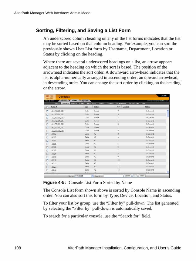
AlterPath Manager Web Interface: Admin Mode
108 AlterPath Manager Installation, Configuration, and User’s Guide
Sorting, Filtering, and Saving a List FormAn underscored column heading on any of the list forms indicates that the list may be sorted based on that column heading. For example, you can sort the previously shown User List form by Username, Department, Location or Status by clicking on the heading.
Where there are several underscored headings on a list, an arrow appears adjacent to the heading on which the sort is based. The position of the arrowhead indicates the sort order. A downward arrowhead indicates that the list is alpha-numerically arranged in ascending order; an upward arrowhead, in descending order. You can change the sort order by clicking on the heading or the arrow.
Figure 4-5: Console List Form Sorted by Name
The Console List form shown above is sorted by Console Name in ascending order. You can also sort this form by Type, Device, Location, and Status.
To filter your list by group, use the “Filter by” pull-down. The list generated by selecting the “Filter by” pull-down is automatically saved.
To search for a particular console, use the “Search for” field.

Configuration and Administration 109
AlterPath Manager Web Interface: Admin Mode
Using the Form Input FieldsWhen typing in data into any of the input fields, note the following conventions:
• In the web form (as it appears on the screen), all required fields are shown in red.
• With some exceptions, fields cannot contain special or reserved (non alphanumeric) characters. If you enter an invalid character, the system generates the message that indicates what characters are not allowed.
• The underbar character (_) is allowed in device names, but the hyphen (-) is not allowed:
Verifying Error MessagesTo verify an error message, you can view the form or screen in question by clicking on the error message. This feature allows you to verify or check the error message against the form.
Figure 4-6: Device Configuration Error Message
Clicking the error message, generates the form in error:
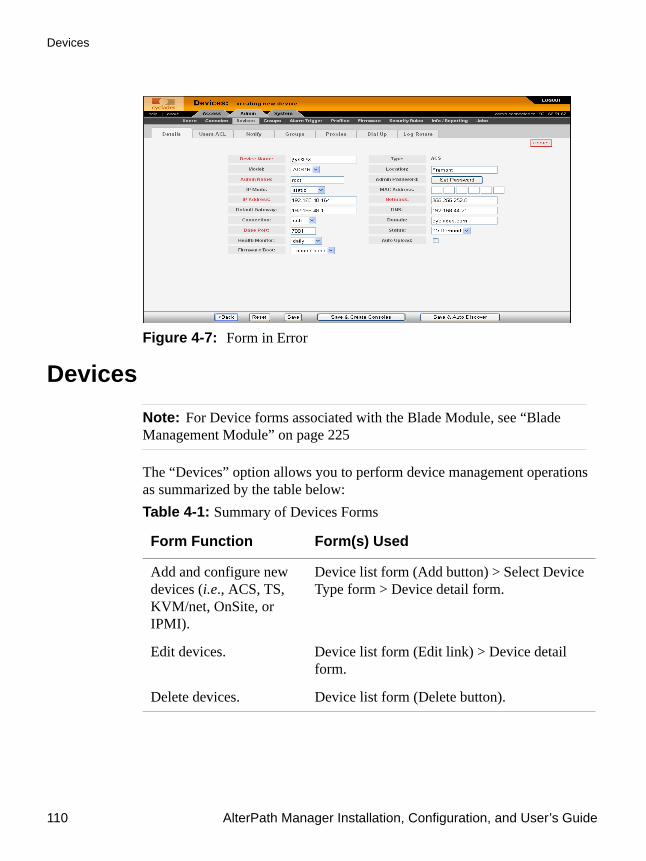
Devices
110 AlterPath Manager Installation, Configuration, and User’s Guide
Figure 4-7: Form in Error
DevicesNote: For Device forms associated with the Blade Module, see “Blade Management Module” on page 225
The “Devices” option allows you to perform device management operations as summarized by the table below: Table 4-1: Summary of Devices Forms
Form Function Form(s) Used
Add and configure new devices (i.e., ACS, TS, KVM/net, OnSite, or IPMI).
Device list form (Add button) > Select Device Type form > Device detail form.
Edit devices. Device list form (Edit link) > Device detail form.
Delete devices. Device list form (Delete button).

Configuration and Administration 111
Devices
Note: The form names do not necessarily appear on the actual form. Because some forms do not have titles, these names are used to distinguish each form as well as to reflect the form function. For example: Devices List form.
Upload device firmware, bootcode or configuration.
Device list form (Upload button).
Configure device health monitor.
Device detail form (Health Monitor input field).
Configure Dial Up and enable PPP connection for out-of-band access to remote device (ACS)
Dial Up form
Run the Device Discovery Wizard.
Device detail form (Save / Auto Discover button).
Run the Console Wizard. Device Discovery form (Save / Create Console button).
Configure KVM Viewer. KVM Viewer form (Device detail form > KVM Viewer form).
Search, sort, and save list of devices.
Devices List form.
Assign type of web proxy to access a target device through the web.
Proxies form.
Configure modem user, password and related parameters to enable dial up / dial out functions.
Dial Up
Table 4-1: Summary of Devices Forms (Continued)
Form Function Form(s) Used

Devices
112 AlterPath Manager Installation, Configuration, and User’s Guide
Supporting forms that you may need to access and manage your devices are:
• Consoles List form• Console Detail form• Firmware form• Profiles form
Because target consoles are part of your devices, it is often necessary to work with device and console management forms together. Also, you may need to refer to the Firmware form for any information you might need pertaining to device firmware.
When new ACS or TS firmware is imported through the AlterPath Manager, the new firmware is added to the database and is reflected in the Firmware List form and in the Firmware/Boot dropdown list in the lower left region of the ACS or TS Device Details form.
Device List FormThe Devices List form, which is the default devices form, allows you to view a list of devices that are configured in the AlterPath Manager. From this form, you can add, modify, or delete devices.

Configuration and Administration 113
Devices
Figure 4-8: Devices List Form Table 4-2: Device List Form
Element Definition
[checkbox adjacent to each device name]
Checkbox to select the device to delete it or to upload configuration or firmware (refer to the buttons below the form to enable these commands).
Name Device name. Click on a device name to edit the device configuration, connect to the device CLI, view the device log, or to connect to the device’s web management interface (WMI). Click on the column title (Name) to change the sort order.
Type The type of device (i.e, TS, ACS, KVM/net or IPMI).

Devices
114 AlterPath Manager Installation, Configuration, and User’s Guide
Upload This column indicates if the device requires a firmware or configuration upload. If required, then select the checkbox adjacent to the device name and click on the “Upload” button.
NOTE: The AlterPath Manager supports firmware and configuration upgrades for the following products:
- ACS and TS: Firmware and configuration
- KVM: Firmware and configuration
- OnSite: Configuration only
Firmware The firmware version for this device.
Status Status of the device: Enabled, Disabled or OnDemand. OnDemand means that the device is enabled only upon user connection.
Filter By A drop-down box that lets you select a filter element from a list of one or more. After you select the filter element, press Enter, and all items that match the filter element will be displayed.
Search For A field box that accepts a string. After you enter the string into the field, press Enter, and all items that match the filter selection and the field entry, will be displayed.
Add Button used to add new devices.
Delete Button used to delete any devices selected for deletion.
Table 4-2: Device List Form (Continued)
Element Definition
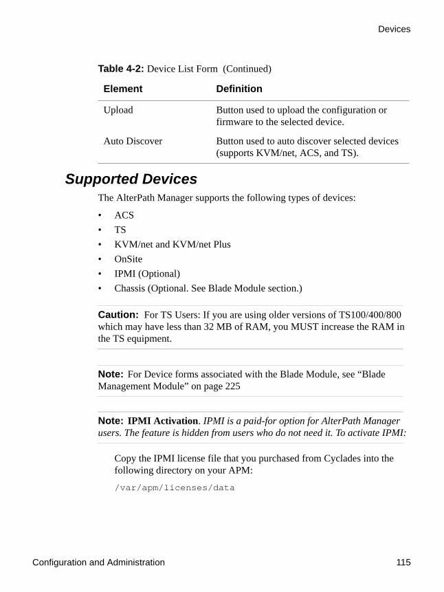
Configuration and Administration 115
Devices
Supported DevicesThe AlterPath Manager supports the following types of devices:
• ACS• TS• KVM/net and KVM/net Plus• OnSite• IPMI (Optional)• Chassis (Optional. See Blade Module section.)
Caution: For TS Users: If you are using older versions of TS100/400/800 which may have less than 32 MB of RAM, you MUST increase the RAM in the TS equipment.
Note: For Device forms associated with the Blade Module, see “Blade Management Module” on page 225
Note: IPMI Activation. IPMI is a paid-for option for AlterPath Manager users. The feature is hidden from users who do not need it. To activate IPMI:
Copy the IPMI license file that you purchased from Cyclades into the following directory on your APM:
/var/apm/licenses/data
Upload Button used to upload the configuration or firmware to the selected device.
Auto Discover Button used to auto discover selected devices (supports KVM/net, ACS, and TS).
Table 4-2: Device List Form (Continued)
Element Definition

Devices
116 AlterPath Manager Installation, Configuration, and User’s Guide
To Add a DeviceTo add any of these devices, follow the steps below:
1. From the menu panel select “Devices”
The system displays the Device List form.2. From the Device List form, click on “Add” located at the bottom of the
form.
The system displays the Select Device Type form.
Figure 4-9: Select Device Type Form
3. From the Select Device Type form, select from the type of device (TS, ACS, KVM/net, OnSite, or IPMI) you wish to add, and then click on the “Submit” button.
The system displays the Device Detail form based on the selected device type. The example below shows the Devices Detail form for the device type, KVM/net:
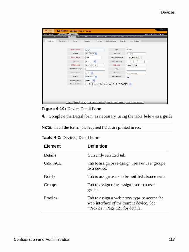
Configuration and Administration 117
Devices
Figure 4-10: Device Detail Form
4. Complete the Detail form, as necessary, using the table below as a guide.
Note: In all the forms, the required fields are printed in red.
Table 4-3: Devices, Detail Form
Element Definition
Details Currently selected tab.
User ACL Tab to assign or re-assign users or user groups to a device.
Notify Tab to assign users to be notified about events
Groups Tab to assign or re-assign user to a user group.
Proxies Tab to assign a web proxy type to access the web interface of the current device. See “Proxies,” Page 121 for details.
Devices
118 AlterPath Manager Installation, Configuration, and User’s Guide
KVM Viewer Tab to set up timeouts and hot keys for KVM viewer (KVM/net and OnSite only)
Dial Up Tab to set dial up parameters.
Log Rotate Tab to display the Log Rotation form, used to set log rotation by configurable size or by selected time interval (available for ACS and TS devices and consoles as well as KVM devices).
Device Name The symbolic name linked to the console server device.
Type Fixed field for type of device (e.g., ACS, KVM, etc.)
Model Drop-down list box to select the model of the current device.
Location Physical location of the device.
Admin Name The admin username (superuser) of the device.
Note: If you plan to upload firmware to a KVM/net with a current firmware version of 2.0.0 or earlier, you must the “Admin Name” field to “root” for the upload to work.
Admin Password Button to invoke a dialog box used to define the Admin’s password. This password is used to access the console server port, but NOT to change the password. You must enter the SAME password registered in the console server.
Table 4-3: Devices, Detail Form (Continued)
Element Definition

Configuration and Administration 119
Devices
IP Mode Drop-down list box. Select “int_dhcp” if the AlterPath Manager is the DHCP server for this device, or “ext_dhcp” if DHCP is served by another server, or “Static” if you are using a static IP address.
See “Configuring Your DHCP Server” on page 142.
MAC Address The MAC address is required if the selected IP mode is “int_dhcp.”
IP Address The IP address of the device is always required.
Netmask As indicated, in dotted notation.
Default Gateway As indicated, in dotted notation.
DNS As indicated, in dotted notation.
Connection Dropdown list box to select the connection protocol used between the AlterPath Manager and the console serial port: “ssh” or “telnet.”
Domain Domain Name
Base Port TCP port number allocated in the first serial port of the console server.
Table 4-3: Devices, Detail Form (Continued)
Element Definition

Devices
120 AlterPath Manager Installation, Configuration, and User’s Guide
Status Dropdown list box to select:
Enable - connection between the AlterPath Manager and the device/console is ALWAYS established.
Disable - no connection is established, and all child consoles follow this configuration.
OnDemand - connection is established only upon user’s request.
Health Monitor The frequency in which the Health Monitor operates to monitor the system (Never, Daily, Weekly or Monthly).
Auto Upload Check “Auto Upload” if you want your configuration automatically uploaded when you save it. See “Difference between Auto Upload and Manual Upload” on page 143.
Firmware/Boot Dropdown list to select any firmware or bootcode to upload. You select the firmware to upload, and then when you upload the configuration for the device, you can select the checkbox to upload the firmware as well. Available on KVM/net, KVM/net Plus, ACS, and TS.
Note: If you upload the firmware to a KVM/net currently running FW version 2.0.0 or earlier, you must configure the “Admin Name” for the device as “root”.
Back Button to return to the previous page.
Reset Button to reset the form.
Table 4-3: Devices, Detail Form (Continued)
Element Definition

Configuration and Administration 121
Devices
5. Click on the “Save” button when done.
6. Select “Devices” from the main menu panel to return to the Device List form and verify your entry.
Note: For Health Monitoring to work with alarms, you must create the alarm triggers. See “Configuring Alarms for Device Health Monitoring” on page 174.
The Device detail form for TS is similar to that of the ACS. The Model dropdown box provides you with a list of TS models to select from.
ProxiesThe AlterPath Manager includes a web proxy server so that connections to the native web interface of any supported device go through the AlterPath Manager. This feature enables the AlterPath Manager to:
• Connect users through the AlterPath Manager to remote servers that it controls (e.g., IBM Blade, KVM/net switches, OnSite units, ACS/TS units, and other servers) in connection with any web interface.
• Provide a secure mechanism for AlterPath Manager clients to access remote servers.
• Configure remote AlterPath devices directly from the AlterPath Manager.
Save Button to save all Device configuration entered in this form.
Save & Create Consoles
Button to initiate the Console Wizard and save the resulting settings.
Save & Auto Discover Button to initiate the Device Discovery Wizard and save the resulting settings for the ACS, TS, or KVM/net.
Table 4-3: Devices, Detail Form (Continued)
Element Definition

Devices
122 AlterPath Manager Installation, Configuration, and User’s Guide
Proxy TypesThere are three types of proxy you can configure for a device:
Warning! When you assign “Forward Proxy using ARP” or “Forward Proxy without ARP”, all ports of the proxied device are reachable from the workstation from which the user is logged in. It is important that all console ports are configured with an authentication type other than None.
Table 4-4: Types of Web Proxy
Proxy Type Function
Reverse Proxy Reverse proxy allows any web server to be viewed through the proxy agent. The web server appears to the user as a subdirectory of the proxy server’s document tree.
Advantages: Target server does not need to have a routable IP address; not accessible outside the AlterPath Manager; user workstation and network does not need to know about the target web server.
Forward Proxy without ARP
A forward proxy acts as a gateway for a client’s browser, sending HTTP requests on the client’s behalf to the Internet. The proxy protects your inside network by hiding the client’s actual IP address and using its own instead. When the outside HTTP server receives the request, it sees the request or address as originating from the proxy server, not from the actual client.
Forward Proxy using ARP (Address Resolution Protocol)
Proxy ARP is the technique in which one host answers ARP requests intended for another machine. By assuming its identity, the router accepts responsibility for routing packets to the intended destination. Proxy ARP can help machines on a subnet reach remote subnets without configuring routing or a default gateway.

Configuration and Administration 123
Devices
The constraints that are set for all proxies rely on IP addresses only. Any user from a workstation where there is another user logged into the AlterPath Manager will have access (as long as the device does not require authentication) to all devices that are being proxied for that user.
Web Proxy Configuration
To Configure the Web ProxyTo create or configure a proxy for a device, follow the steps below:
1. Open the Device List form
2. If the device is new, click on the “Add” button.
(If the Device already exists, highlight the device and click on the “Edit” button.)
3. From the Device Edit form, select the “Proxies” tab.
The system displays the Device Proxies form.
Figure 4-11: Device Proxies Form
4. From the Device Proxies form select the type of web proxy you wish to assign for the current device.

Devices
124 AlterPath Manager Installation, Configuration, and User’s Guide
Note: For “Forward Proxy” settings with the device on a different network than your PC (i.e., a private network), you must set your PC’s default gateway to the IP address of the AlterPath Manager’s Eth0 port and the device’s default gateway to the IP address of the AlterPath Manager’s Eth1 port. If modem mode is the primary connection mode used, the PPP local IP address should be used rather than the Ethernet IP address. See “Configuring PC Routing Tables” on page 124.
5. Click on “Save” to complete the procedure.
To Verify your Proxy Setting1. To verify your configuration, return to the Devices List form.
2. Left click a device for which you configured a proxy setting.
A group of small boxes with the choices”EDIT,” “LOG,” “CLI Applet” and/or “CLI JWS,” and “WEB.” will appear.
3. Select “WEB.”
This will launch a browser window that displays the web pages of the selected device.
Configuring PC Routing Tables
Caution: A console associated with a device on a private network cannot be accessed via an APM web proxy connection.
If any of your devices are on a network that is different than your PC’s network, you will need to configure the routing table on your PC so the private network can be accessed by a Forward Proxy setting. The APM will connect to your local network (the one with the PC) via the Eth0 port. The APM will connect to the private network via the Eth1 port.

Configuration and Administration 125
Devices
In this procedure, the following parameters are assumed:
To Configure PC Routing Tables
Windows PC Routing Table
1. Open a command line window.
2. At the command prompt, enter the following command:c:\>route -p add 10.10.10.0 mask 255.255.255.0 192.168.48.162
Note: Adding the “-p” to the “route add” command, makes the new route stay configured when you reboot your PC.
3. Verify that the route was added by running the following command:c:\>netstat -rn
APM Eth0 IP Address 192.168.48.162
Local Network Default Gateway 192.168.48.1
Local Network Net Mask 255.255.252.0
Private Network IP Address 10.10.10.0
APM Eth1 IP Address and Private Network Default Gateway
10.10.10.2
Private Network Net Mask 255.255.255.0
Private Network Device IP Address 10.10.10.10

Devices
126 AlterPath Manager Installation, Configuration, and User’s Guide
You should see a display similar to the following:
Linux PC Routing Table
1. Log onto a Linux shell window as “root”.
2. At the command prompt, enter the following command:# route add -net 10.10.10.0 netmask 255.1255.255.0 gw 192.168.48.162
3. Verify that the route was added by running the following command:
# netstat -rn
C:\Documents and Settings\Gregg>netstat -rn
Route Table===========================================================================Interface List0x1 ........................... MS TCP Loopback interface0x2 ...52 2d bc c2 f5 b4 ...... MAC Bridge Miniport - Packet Scheduler Miniport======================================================================================================================================================Active Routes:Network Destination Netmask Gateway Interface Metric 0.0.0.0 0.0.0.0 192.168.48.1 192.168.48.26 10 10.10.10.0 255.255.255.0 192.168.48.162 192.168.48.26 1 127.0.0.0 255.0.0.0 127.0.0.1 127.0.0.1 1 192.168.48.0 255.255.252.0 192.168.48.26 192.168.48.26 10 192.168.48.26 255.255.255.255 127.0.0.1 127.0.0.1 10 192.168.48.255 255.255.255.255 192.168.48.26 192.168.48.26 10 224.0.0.0 240.0.0.0 192.168.48.26 192.168.48.26 10 255.255.255.255 255.255.255.255 192.168.48.26 192.168.48.26 1Default Gateway: 192.168.48.1===========================================================================Persistent Routes: Network Address Netmask Gateway Address Metric 10.10.10.0 255.255.255.0 192.168.48.162 1

Configuration and Administration 127
Devices
You should see a display similar to the following:
Disabling the ProxyIn the WMI device configuration, (under the “Proxies” tab) setting “Web Proxy” to “none enabled” will prevent anyone from accessing the selected device’s web user interface.
Configuring Ports to be ProxiedWhen Forward Proxy (with or without ARP) is enabled for a device, the default proxied ports are 80 and 443. To change the opened ports, see “Changing the Ports to be Proxied” on page 311.
Dial Up and Dial BackThe “Dial Up” form allows you to configure the current device for dial-up connection to the network.
The same form is also used to configure the device for dial back. Currently, the “Dial Back” feature only applies to ACS devices. When an ACS unit is configured for dial back, the AlterPath Manager can dial out to the remote ACS unit and authenticate with the ACS. Once authenticated, the ACS drops the line and dials out to a pre-defined number. Simultaneously, the AlterPath Manager sets its modems into a state where it is ready to receive a call. The system allows all remote sites to call back to the same number and support multiple, simultaneous call back connections to the AlterPath Manager.
When the AlterPath Manager receives the dial back call, the authentication is repeated. Upon successful authentication, the system establishes a PPP session and opens the console connection.
Call back connections are included in the log messages.
# netstat -rnKernel IP routing tableDestination Gateway Genmask Flags MSS Window irtt Iface10.10.10.0 192.168.48.162 255.255.255.0 UG 0 0 0 eth0192.168.48.0 0.0.0.0 255.255.252.0 U 0 0 0 eth0169.254.0.0 0.0.0.0 255.255.0.0 U 0 0 0 eth0127.0.0.0 0.0.0.0 255.0.0.0 U 0 0 0 lo0.0.0.0 192.168.48.1 0.0.0.0 UG 0 0 0 eth0

Devices
128 AlterPath Manager Installation, Configuration, and User’s Guide
Note: For dial back to work, you must configure it from the web interface and the CLI.
To Configure Dial Up / Dial BackTo configure Dial Up or Dial Back, follow the steps below:
1. Go to Devices > Dial Up.
The system displays the Device Dial Up form.
Device dial up forms vary, depending upon the device being configured for dial up. The following is a device dial up form for a KVM/net.
Figure 4-12: Device Dial Up Form (KVM device)
The following is a device dial up form for an ACS.

Configuration and Administration 129
Devices
Figure 4-13:Device Dial Up Form (ACS device)
The following is an example of a fully expanded ACS device dial up form.
Figure 4-14:Fully Expanded ACS Device Dial Up Form.

Devices
130 AlterPath Manager Installation, Configuration, and User’s Guide
2. Complete the form using the table below as a guide: .Table 4-5: Fully Expanded Dial Up Form
Element Definition
Modem Mode Drop-down box to select how you want your PPP connection to be used:
Disabled - default value.
Primary Network - uses a modem connection as the primary way to connect to a device. The connection is dropped when the last user disconnects.
Network Backup - uses a modem connection only if the network connection is unavailable.
PPP Phone If Modem Mode is enabled (either as Primary or Network Backup), then this field is required for PPP connection. Enter the complete PPP phone number to establish PPP connection to a device or console via web interface, CLI, or SSH.
Use ISDN Check box enables ISDN when selected (ISDN modem and connection required). See “Modem Dial Back for ACS” on page 308 and “ISDN Configuration” on page 310.
ISDN cannot be used with OTP
Dialback Mode Select whether to “enable” or “disable” dialback mode (ACS only).
Dialback cannot be used with OTP.
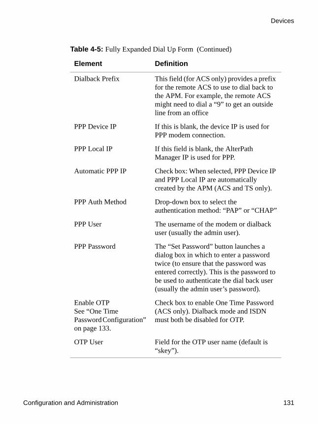
Configuration and Administration 131
Devices
Dialback Prefix This field (for ACS only) provides a prefix for the remote ACS to use to dial back to the APM. For example, the remote ACS might need to dial a “9” to get an outside line from an office
PPP Device IP If this is blank, the device IP is used for PPP modem connection.
PPP Local IP If this field is blank, the AlterPath Manager IP is used for PPP.
Automatic PPP IP Check box: When selected, PPP Device IP and PPP Local IP are automatically created by the APM (ACS and TS only).
PPP Auth Method Drop-down box to select the authentication method: “PAP” or “CHAP”
PPP User The username of the modem or dialback user (usually the admin user).
PPP Password The “Set Password” button launches a dialog box in which to enter a password twice (to ensure that the password was entered correctly). This is the password to be used to authenticate the dial back user (usually the admin user’s password).
Enable OTPSee “One Time Password Configuration” on page 133.
Check box to enable One Time Password (ACS only). Dialback mode and ISDN must both be disabled for OTP.
OTP User Field for the OTP user name (default is “skey”).
Table 4-5: Fully Expanded Dial Up Form (Continued)
Element Definition

Devices
132 AlterPath Manager Installation, Configuration, and User’s Guide
3. Click on “Save” to save.
4. If you are configuring for dial back, ensure that you have fulfilled the other requirements outlined in the next section.
Other Requirements for Dial Out / Dial BackTo enable device or console access through dial out or dial back, you must configure the following:
From the AlterPath Manager:
1. Go to the web interface: “Console” Detail Form:
• Status: Be sure to select “OnDemand” for this field.
2. From the Dial Up form, provide the following parameter values:
• PPP User - The user that you have configured in the APM as the admin user for the ACS.
• PPP Password
OTP Passphrase The “Set Passphrase” button launches a dialog box in which to enter a password which is used for OTP encryption. You can skip this if you select the “Random Passphrase” check box below this button.
Auto Refresh Eliminates the need to periodically manually refresh the OTP sequence. See “One Time Password Configuration” on page 133.
Random Passphrase Check this box to randomly generate an OTP passphrase.
Reset Sequence Button to manually reset the OTP. The sequence will be reset upon the next dial up connection or upload.
Table 4-5: Fully Expanded Dial Up Form (Continued)
Element Definition
Configuration and Administration 133
Devices
• PPP Auth Method - Select PAP or CHAP.
Note: If the PPP User is not configured in the APM, then the main user is used for dial out and dial back.
From the ACS:
1. Using a serial console or a telnet or ssh connection, create a new user and password for the ACS using the commands:
• adduser <ppp_user>• passwd <ppp_user>
Note: See “Changing the Ports to be Proxied” under “Advanced Configuration.”
Other Requirements for Dial Back (ACS Only)The dial back feature works for ACS only. To set an ACS device for dial back, you must also configure the following:
From the AlterPath Manager:1. Using the serial console interface, edit the file:
/var/apm/apm.properties
2. Add the AlterPath Manager dial back number in the following parameter:dial.apm_phone_number=<phone number>
One Time Password Configuration
Note: The One Time Password feature is only supported when an analog modem is used, not when an ISDN modem is used.
The ACS does not support external modems connected to serial ports.Only PCMCIA modem cards are supported on the ACS.
One Time Password is configured on the Dial Up form when you are either adding or editing an ACS configuration. An example One Time Password

Devices
134 AlterPath Manager Installation, Configuration, and User’s Guide
setup form is shown in the following figure, “Dial Up Form with One Time Password Setup.”
Figure 4-15:Dial Up Form with One Time Password Setup
To Enable the OTP Authentication for Dialup
Caution: It is strongly recommended that you do not attempt to upload firmware using a modem connection.
Note: This feature is not available with ISDN modems.
1. Set the “Modem Mode” field to either “Primary Network’ or “Network Backup.”
This enables the “Enable OTP” check box and causes the field labels “PPP Phone,” “PPP User,” and “PPP Password” to turn red (indicating the requirement to fill in these fields).
Note: If you check the “Automatic PPP IP” check box, you will not need to fill in the “PPP Device IP” and “PPP Local IP” fields, as these parameters will automatically be created by the APM. The APM does this by reading a list of

Configuration and Administration 135
Devices
PPP device IPs and PPP local IPs in its database. It will then search, starting from 10.0.0.1 until it finds 2 free IP addresses.
If the “PPP Device IP” and “PPP Local IP” fields have already been filled in, the “Automatic PPP IP” check box will toggle these fields as filled in (when unchecked) and as filled in with a grayed out “Auto” (when checked).
2. Fill in the “PPP Phone” field with the phone number on which the ACS modem is installed.
3. Fill in the “PPP User” field with a user name. This is normally the admin user name.
Note: If you fill in the name of a user not already configured on the APM, the user will automatically be configured as the PPP user. You will not need to configure this user separately, unless you want the PPP user to be on a notification list.
4. Click the “PPP Password” box. This generates a dialog box in which you enter the PPP user’s password and then confirm it.
5. Check the “Enable OTP” check box.
This causes the following items to become visible: “OTP User” field, “OTP Passphrase” button, “Auto Refresh” check box, and “Random Passphrase” check box.
Note: The OTP check box does not appear when an ISDN modem is being configured.
6. You can either enter a new OTP user in the “OTP User” field, or leave it as “skey” (the default user name).
7. You will either need to fill in the “OTP Passphrase” field or check the “Random Passphrase” check box.
8. Enable “Auto Refresh” This will refresh the OTP sequence by resetting the sequence number to 499 automatically when you dial in and there are fewer than 20 one time passwords remaining.

Devices
136 AlterPath Manager Installation, Configuration, and User’s Guide
If you do not check this box, the sequence needs to be refreshed manually by clicking the “Reset Sequence” button and then doing an upload.
Note: Checking the “Auto Refresh” box disables the “Reset Sequence” button.
9. If you want OTP to trigger alarms, enable the “OTP alarm” trigger from the “Alarm Trigger” menu.
KVM/net Device Detail FormThe example below shows the Device Detail form that is used to configure the device type, KVM/net:
Figure 4-16: KVM/net Device Detail Form
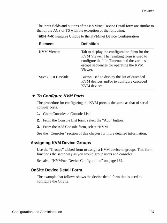
Configuration and Administration 137
Devices
The input fields and buttons of the KVM/net Device Detail form are similar to that of the ACS or TS with the exception of the following:
To Configure KVM PortsThe procedure for configuring the KVM ports is the same as that of serial console ports.
1. Go to Consoles > Console List.
2. From the Console List form, select the “Add” button.
3. From the Add Console form, select “KVM.”
See the “Consoles” section of this chapter for more detailed information.
Assigning KVM Device GroupsUse the “Groups” tabbed form to assign a KVM device to groups. This form functions the same way as you would group users and consoles.
See also: “KVM/net Device Configuration” on page 162.
OnSite Device Detail FormThe example that follows shows the device detail form that is used to configure the OnSite.
Table 4-6: Features Unique to the KVM/net Device Configuration
Element Definition
KVM Viewer Tab to display the configuration form for the KVM Viewer. The resulting form is used to configure the Idle Timeout and the various escape sequences for operating the KVM Viewer.
Save / List Cascade Button used to display the list of cascaded KVM devices and/or to configure cascaded KVM devices.

Devices
138 AlterPath Manager Installation, Configuration, and User’s Guide
Figure 4-17: Device Detail Form for the AlterPath OnSite
Be sure the model you select in the “Model” field matches the model number of your OnSite. OnSite model numbers and their meanings are shown in the following table:
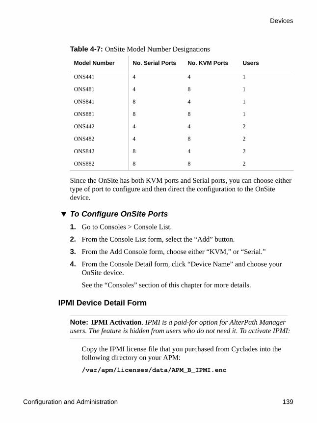
Configuration and Administration 139
Devices
Since the OnSite has both KVM ports and Serial ports, you can choose either type of port to configure and then direct the configuration to the OnSite device.
To Configure OnSite Ports1. Go to Consoles > Console List.
2. From the Console List form, select the “Add” button.
3. From the Add Console form, choose either “KVM,” or “Serial.”
4. From the Console Detail form, click “Device Name” and choose your OnSite device.
See the “Consoles” section of this chapter for more details.
IPMI Device Detail Form
Note: IPMI Activation. IPMI is a paid-for option for AlterPath Manager users. The feature is hidden from users who do not need it. To activate IPMI:
Copy the IPMI license file that you purchased from Cyclades into the following directory on your APM:
/var/apm/licenses/data/APM_B_IPMI.enc
Table 4-7: OnSite Model Number Designations
Model Number No. Serial Ports No. KVM Ports Users
ONS441 4 4 1
ONS481 4 8 1
ONS841 8 4 1
ONS881 8 8 1
ONS442 4 4 2
ONS482 4 8 2
ONS842 8 4 2
ONS882 8 8 2

Devices
140 AlterPath Manager Installation, Configuration, and User’s Guide
The example below shows the Device Detail form for the device type, IPMI. The device configuration for IPMI is actually the configuration for the IPMI Baseboard Management Controller (BMC) that is embedded in the system.
The input fields and buttons for this form are also similar to the other Device Detail forms with the exception of the following:
When you configure an IPMI device, the AlterPath Manager will allow you to create one console which uses the device name as a root and adds “_01”. There are two ways you can create this console:
• From the current IPMI Device Detail form. • From the Console Detail form.
Table 4-8: Devices, Details Form (IPMI)
Element Definition
Model Select the IPMI version.
“IPMI 1.5 Intel” allows you to create an IPMI console on which authorized users can log in.
“IPMI 1.5” does not allow the creation of an IPMI console.
Note: IPMI 2.0 is not supported and does not work with the APM.
Authentication Information
Dropdown box to select the authentication type.
Encryption Required Dropdown box to select the encryption type.
Group Membership The groupname to which the device belongs.
Power Control Enabled (Y/N) to enable/disable power control.
Power On Button to switch on the IPMI server.
Power Off Button to switch off the IPMI server.
Display Sensors/Log Button to display a new form that contains two tabs for viewing sensors or logs from the BMC, respectively.

Configuration and Administration 141
Devices
To Use the IPMI Device Detail Form to Add a Console1. Open the IPMI Device Detail form (Devices: Device List > Device
Detail).
2. From the IPMI Device Detail form, click on the “Save/Create Console” button.
The system launches the Console Wizard.
3. Follow the system instructions and enter all relevant information, as needed.
Note: You may change the default console name which is the same as the device name.
4. Once you have saved the Console configuration, the system returns you to the Device Detail form.
Using the IPMI Console Detail Form to Add a ConsoleSee “To Add an IPMI Console from Console Detail Form” on page 198.
To View Sensors or Logs from the BMCTo view the sensors and logs from the BMC:
1. From the IPMI Device Detail form, click on the “Display Sensors/Logs” button.
The system displays a form containing two tabs:
• “Sensors” tabbed form (default) - displays the current values of all sensors. This form refreshes every 15 seconds.
• “Logs” tabbed form - displays all logs read from the BMC. You may clear the log database by clicking on the “Clear” button, but be careful because this command will erase all logs from the BMC database and it cannot be undone.

Devices
142 AlterPath Manager Installation, Configuration, and User’s Guide
Configuring Your DHCP ServerA DHCP server is built into the AlterPath Manager. You can use your company’s DHCP server or the AlterPath Manager as your DHCP server. If you are not using a DHCP server, then you may use a static IP address.
The Device Definition window provides three IP modes in which to configure your DHCP server or static IP address. The IP address that you use depends on what type of mode you use.
Function of the Status FieldThe “Status” field of the Device Detail form indicates whether the connection between the AlterPath Manager and the device/console is “Enabled” (i.e., permanently connected), “Disabled” (no connection established), or “OnDemand.”
IP Mode When to use this mode
int_dhcp (internal) Select this mode if you are using the AlterPath Manager as your DHCP server. You decide on what IP address you wish to use and then save the configuration in the Device Definition form.
ext_dhcp (external) Select this mode if you already have a DHCP server in your LAN that you wish to use. You will need to get from your System Administrator the IP address allocated for your company’s DHCP server.
Static Select this if using a static IP address. When using the static mode, you (or your LAN/System
Administrator) must first connect to the console server using the serial console to enter the IP address. You must then enter that same IP address in the AlterPath Manager through the Device Definition form.
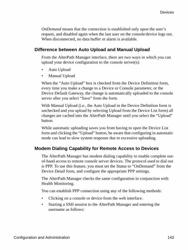
Configuration and Administration 143
Devices
OnDemand means that the connection is established only upon the user’s request, and disabled again when the last user on the console/device logs out. When disconnected, no data buffer or alarm is available.
Difference between Auto Upload and Manual UploadFrom the AlterPath Manager interface, there are two ways in which you can upload your device configuration to the console server(s):
• Auto Upload• Manual Upload
When the “Auto Upload” box is checked from the Device Definition form, every time you make a change to a Device or Console parameter, or the Device Default Gateway, the change is automatically uploaded to the console server after you select “Save” from the form.
With Manual Upload (i.e., the Auto Upload in the Device Definition form is unchecked and you upload by selecting Upload from the Device List form) all changes are cached into the AlterPath Manager until you select the “Upload” button.
While automatic uploading saves you from having to open the Device List form and clicking the “Upload” button, be aware that configuring in automatic mode can lead to slow system response due to excessive uploading.
Modem Dialing Capability for Remote Access to DevicesThe AlterPath Manager has modem dialing capability to enable complete out-of-band access to remote console server devices. The protocol used to dial out is PPP. To use this feature, you must set the Status to “OnDemand” from the Device Detail form, and configure the appropriate PPP settings.
The AlterPath Manager checks the same configuration in conjunction with Health Monitoring.
You can establish PPP connection using any of the following methods:
• Clicking on a console or device from the web interface.• Starting a SSH session to the AlterPath Manager and entering the
username as follows:

Devices
144 AlterPath Manager Installation, Configuration, and User’s Guide
<username>:<console name>
• Uploading device configuration
Modem Mode
There are three modes of PPP connection:
Health Monitoring and PPP Settings
The AlterPath Manager uses the same PPP settings to enable Health Monitoring. The Health Monitoring feature is not affected regardless of whether the Mode selected is “Primary Network” or “Network Backup.”
Actions Not Recommended While Using PPP
Do not change the Device IP or the Device Name (including deleting or disabling it) while running PPP as this will cause a disconnection if no upload is in progress. Any device change during an upload will prevent your upload from being saved.
Configuring the Modem Dialing Capability
To configure the modem dialing capability, follow the steps below:
Table 4-9: PPP Connection Modes
Connection Mode Definition
Disabled This is the default mode.
Primary Network Select this to establish a PPP connection whenever a user connects to a device or console. The modem connection remains as long as there is a console port open.
Network Backup Select this to use Ethernet to connect to a device. In the event that the device becomes unreachable via Ethernet, the AlterPath Manager establishes a PPP connection as a backup network whenever a device/console access is requested.

Configuration and Administration 145
Devices
1. From the Dial Up form (Devices > Add > Dial Up form), select the Modem Mode:
Modem Mode provides three choices:
2. From the Status field of the Devices Detail form, select “On Demand.”
3. Complete the PPP settings as follows:
4. Click on “Save” to complete the procedure.
Table 4-10: Modem Mode Choices
Option Use this option if you want to use PPP . . .
Primary Network
As the primary mode of connection.
Network Backup Only when the network fails.
Disable Default value. (If you select this, then you don’t need to do this procedure.)
Table 4-11: PPP Settings
PPP Setting Definition
PPP Device IP Optional. IP address for the current device.
PPP Local IP Optional. Local IP address for using PPP.
PPP Phone Required. The complete PPP phone number.
PPP Auth Method
Select the authentication method: “PAP” or “CHAP”
PPP User Username of the modem user.
PPP Password Password of the modem user.
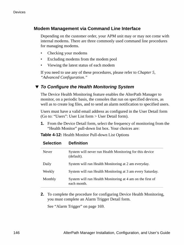
Devices
146 AlterPath Manager Installation, Configuration, and User’s Guide
Modem Management via Command Line InterfaceDepending on the customer order, your APM unit may or may not come with internal modems. There are three commonly used command line procedures for managing modems.
• Checking your modems• Excluding modems from the modem pool• Viewing the latest status of each modem
If you need to use any of these procedures, please refer to Chapter 5, “Advanced Configuration.”
To Configure the Health Monitoring SystemThe Device Health Monitoring feature enables the AlterPath Manager to monitor, on a periodic basis, the consoles that run on specified devices, as well as to create log files, and to send an alarm notification to specified users.
Users must have a valid email address as configured in the User Detail form (Go to: “Users”: User List form > User Detail form).
1. From the Device Detail form, select the frequency of monitoring from the “Health Monitor” pull-down list box. Your choices are:
2. To complete the procedure for configuring Device Health Monitoring, you must complete an Alarm Trigger Detail form.
See “Alarm Trigger” on page 169.
Table 4-12: Health Monitor Pull-down List Options
Selection Definition
Never System will never run Health Monitoring for this device (default).
Daily System will run Health Monitoring at 2 am everyday.
Weekly System will run Health Monitoring at 3 am every Saturday.
Monthly System will run Health Monitoring at 4 am on the first of each month.

Configuration and Administration 147
Devices
Console WizardThe “Save/Create Consoles” button is used to run the Console Wizard which allows you to configure those consoles connected to a device by following the wizard’s prompts, options, and default values. The wizard automatically configures the console(s) and applies them to the device.
If you use the wizard to define a new device which has no consoles defined, then all the consoles listed will be checked, and the console names generated automatically in the form: <device name>_nnn (where nnn = port number).
If you use the wizard to edit a device which already has consoles defined, then it will detect and list the consoles, but keep them unchecked. You can then decide which console should be checked and have the configuration overridden.
Summary of Console Wizard FormsThe console wizard is composed of a series of configuration pages or forms. Once the wizard is activated, the forms will appear in the following order: Table 4-13: Summary of Console Wizard Forms
Wizard Form Function
Warning This page warns you about any data to be overwritten and the choices you have before proceeding with the wizard.
Defaults Sets the profile, connection protocol, and
authentication type.
Access Select the users who can access the consoles.
Notify Selects the users to who will be notified in the case of an event.
Groups Select the groups to which the console(s) belong.
Console Selection Lists all consoles that have not been configured for this console server. Select the console(s) to be configured by the wizard.

Devices
148 AlterPath Manager Installation, Configuration, and User’s Guide
To Run the Console WizardTo Run the Console Wizard follow the steps below:
1. From the Device List form, select the device you wish to configure and then select “Edit” to modify an existing device, or select “Add” to configure a new device.
a. If you are configuring a new device (you selected “Add”), the system displays a pull down box that lets you select device types. Select the type of device that you want.
b. Click the “Select” button.
The system displays the Device Details form.
Edit Consoles Edits any settings for consoles connected to this console server.
Confirmation Confirms your previous edits and selections. Select “Finish” to save configuration or select “Back” to re-edit.
Upload Progress Indicates the percentage complete and displays any messages or errors. This page is shown if you did not check “Auto Upload” in the Device Details form.
Console Creation Finish This page is shown if you did not select “Auto Upload” from the Device Details form.
Table 4-13: Summary of Console Wizard Forms (Continued)
Wizard Form Function
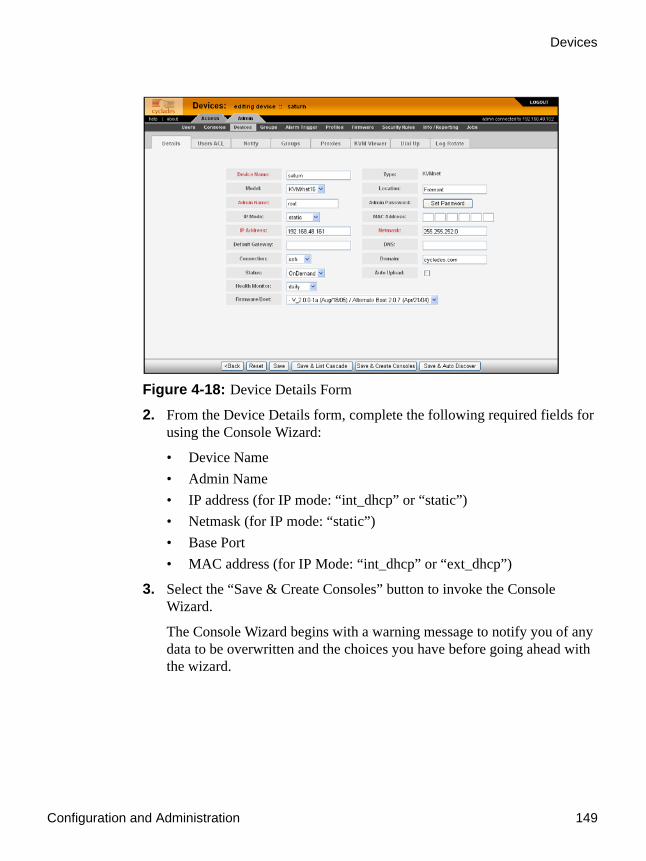
Configuration and Administration 149
Devices
Figure 4-18: Device Details Form
2. From the Device Details form, complete the following required fields for using the Console Wizard:
• Device Name• Admin Name• IP address (for IP mode: “int_dhcp” or “static”)• Netmask (for IP mode: “static”)• Base Port• MAC address (for IP Mode: “int_dhcp” or “ext_dhcp”)
3. Select the “Save & Create Consoles” button to invoke the Console Wizard.
The Console Wizard begins with a warning message to notify you of any data to be overwritten and the choices you have before going ahead with the wizard.
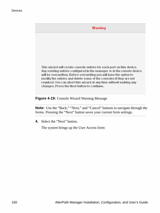
Devices
150 AlterPath Manager Installation, Configuration, and User’s Guide
Figure 4-19: Console Wizard Warning Message
Note: Use the “Back,” “Next,” and “Cancel” buttons to navigate through the forms. Pressing the “Next” button saves your current form settings.
4. Select the “Next” button.
The system brings up the User Access form:

Configuration and Administration 151
Devices
Figure 4-20: Console Wizard Access Form
“USER+” is the default list which contains all users.
The system also adds a plus (+) sign to any added user group that appears in the selection box.
5. Make any necessary selections in the “Select user to console access” box, and click the “Add” button.
The selected users and/or groups will be moved into the “Selected users” box.
6. Click on the “Notify” tab. From the User Notification form, select the user(s) you wish to be notified. This form works the same way as the “Access” form.

Devices
152 AlterPath Manager Installation, Configuration, and User’s Guide
Figure 4-21: Console Wizard Notification Form
7. Click the “Groups” tab and complete the Console Wizard Groups form, as necessary.
8. Select the “Next” button to display the Unconfigured Consoles form:
Figure 4-22:Unconfigured Consoles List

Configuration and Administration 153
Devices
9. Select the unconfigured console(s) that you wish to configure, and then select the “Next” button to display the Edit Console Settings form.
Figure 4-23: Edit Console Settings Form - Page 1
Note: If you need to change the prefix of the console names, type in the new prefix in the “Console Prefix” field and then click on the “Console Prefix” button. The system applies the new prefix to all console names.
10. From the resulting form, modify any settings as needed, and then click on the “IPDU/Outlets” button if necessary.
11. Proceed to the Confirm Console Edits form.

Devices
154 AlterPath Manager Installation, Configuration, and User’s Guide
Figure 4-24: Confirm Console Edits Form
12. Check your console settings from the Confirm Edits form. If information is incorrect, select the “Back” button and repeat steps 10. and 11. Otherwise select the “Finish” button.
Device Discovery (Auto Discover)The Device Discovery feature enables the AlterPath Manager to recognize the current configuration of a Cyclades AlterPath TS, ACS, or KVM/net and, through the use of a wizard, autopopulate the console parameters based on the existing device configuration settings.
Warning! Consoles with the same names will cause the wizard to fail. Since the ACS was designed to accept multiple ports with the same name, in the event that the wizard fails due to ports sharing the same name, you have two options: (1) Fix the configuration problem in the ACS and then run the Device Discovery wizard again. (2) Create consoles through the console wizard and then upload the configuration to ACS to overwrite the old one.

Configuration and Administration 155
Devices
Configuration Requirements
For the “Auto Discover” button to work, you must complete the required fields which are highlighted in red in the Device Definition form:
• IP Address• Netmask or MAC Address• Admin Username• Admin Password
To Run the Device Discovery WizardTo run the Device Discovery Wizard follow the steps below:
1. Log in as admin (or as a user with an admin profile) to the AlterPath Manager
2. From the menu, select “Devices.”
3. From the Devices List form, select the “Add” button to configure the ACS, TS or KVM/net.
4. From the resulting Device definition form, if you are using static IP mode, complete the input fields with particular attention to the following:
• Device Name• Type and Model must match• Enter the Admin Name and Admin Password from the configured
device.• IP Address and Netmask from the configured device.• Select “Static” from the “IP Mode” pull down box.• Place a check mark in the “Auto Upload” box.
If you are using internal DHCP mode, select IP Mode as “int_dhcp” and include the ACS, TS, KVM/net, or OnSite MAC Address.
5. To start the Console Wizard, select the “Save & Auto Discover” button.
The system displays the Warning page (in the Console Wizard Warning Message) which alerts you to the fact that existing consoles will be overwritten if you follow through with the configuration.

Devices
156 AlterPath Manager Installation, Configuration, and User’s Guide
Note: The ACS with SW version 2.3.1 and later is shipped with all ports disabled by default. Auto Discover will not find ports that are disabled, and therefore will not find any ports on a new ACS as shipped from the factory. If this is the case, and you are configuring an ACS using the “Save & Auto Discover” button, you will see the message:
No Console Found
You will need to do one of the following:
Manually enable some console ports by directly logging on to the ACS you are configuring in order to allow the auto discover feature to discover those console ports.
Or:
Select the “Save & Create Consoles” button on the APM device configuration wizard.
6. Select the “Next” button.
The following adding console wizard form appears with the “Access” tab opened:

Configuration and Administration 157
Devices
Figure 4-25:Adding Console Wizard
7. Select the appropriate user(s) from the “Select user to console access:” box, and click the “Add” button.
The selected user name(s) will be moved into the “Selected users” box.
8. Select the “Notify” tab, and select the appropriate user(s) to be notified by email when alarm events occur. Click the “Add” button.
9. Select the “Groups” tab, and select the appropriate group(s) to be associated with this console. Click the “Add” button.
Multiple Auto DiscoverMultiple Auto Discover allows you to launch Auto Discover sessions on multiple devices with the mouse and keyboard actions normally used to perform this task on just one device.
To Start a Multiple Auto Discover Session
1. Go to the Device List form.
2. Click on the check box to the left of any device in the list on which you wish to launch an Auto Discover session.
3. Click on the Auto Discover button shown in the figure that follows.

Devices
158 AlterPath Manager Installation, Configuration, and User’s Guide
Figure 4-26:Selecting Devices for Multiple Auto Discover
The system displays a Warning page (similar to that shown in Figure 4-19, “Console Wizard Warning Message”), which alerts you to the fact that existing consoles will be overwritten if you follow through with the configuration.
4. Continue from here as you would if you were running Auto Discover on just one device.
To Connect to a DeviceTo connect to a device, follow the steps below:
1. From the Device List form, click on the device name to which you wish to connect.
A series of buttons will appear below the device name:
2. Select the “CLI Applet” or “CLI JWS” button.
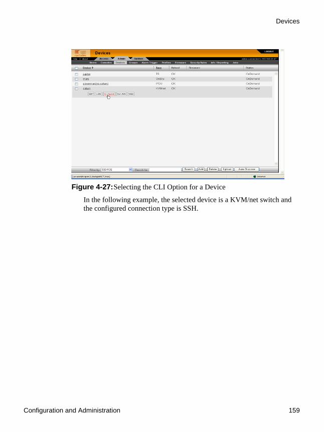
Configuration and Administration 159
Devices
Figure 4-27:Selecting the CLI Option for a Device
In the following example, the selected device is a KVM/net switch and the configured connection type is SSH.

Devices
160 AlterPath Manager Installation, Configuration, and User’s Guide
Figure 4-28: Connection to a Device
If the type of device defined is IPMI, when you connect via CLI to the device, the system connects you to the BMC.
To Delete a DeviceTo delete a device from the AlterPath Manager, follow the steps below:
1. From the Devices List form, select any device you wish to delete by clicking on the checkbox adjacent to the Device name.
2. Select the “Delete” button.
To Delete a Device from a GroupTo delete a device from one or more groups, follow the steps below:
1. From the menu panel, select “Devices.”
The system displays the Devices List form.
2. Under the “Device” column of the Devices List form, click on the “Edit” link of the device you wish to remove from a group.

Configuration and Administration 161
Devices
3. The system displays the Device Detail form for the selected device.
4. From the Device Detail form, click on “Groups.”
The system displays the Device Group form.
5. From the “Selected Groups” view panel of the Device Group form, select the group or groups from which you wish to remove the current device.
6. Click on the “Delete” button.
7. Click on the “Save” button to complete the procedure.
Deleting a Device GroupYou cannot delete a device group using the Device Group form. To delete a device group, select “Groups” from the menu and refer to “Groups” on page 210.
To Upload Firmware to a DeviceUsing the Device Detail form, you can configure the AlterPath Manager to upload firmware from its firmware repository to an ACS, TS, or KVN/net device.
1. From the Device Detail form (Devices: Device List > Device Detail), select the firmware you wish to upload from the Firmware/Boot drop down list.
Note: The Firmware/Boot drop down list only appears in the Device Detail forms of the ACS, the TS, and the KVM/net.
2. Click on the “Save” button.
3. Go back to the Device List form and select the device(s) that need to be uploaded by clicking the corresponding checkbox, and then click “Upload.”

Devices
162 AlterPath Manager Installation, Configuration, and User’s Guide
Figure 4-29: Device Firmware Upload
4. Select “Upload firmware/bootcode” and/or “Upload configuration” to select either a firmware upload, a configuration upload, or both.
5. Click on the “Submit” button.
Note: The “Upload firmware/bootcode” option appears even if the AlterPath Manager firmware repository is empty. If you click on it, you must wait for a while before a message appears to let you know that the firmware repository is empty.
KVM/net Device ConfigurationWhen connected to a KVM/net switch, the “Devices” option also allows you to use the following KVM/net forms:Table 4-14: Forms Used to Configure KVM/net
Form Use this form to:
Device List View KVM/net devices. Create, edit or delete a KVM/net device.

Configuration and Administration 163
Devices
To Configure Escape Sequences and Idle TimeoutA main component of the KVM/net settings is defining the (keyboard) key sequences for users when using the AlterPath Viewer. An escape sequence is a sequence of special characters used to send a command to a device or program. In this case the escape sequence is sent to the KVM/net application. Typically, an escape sequence is coupled with a special character.
The Console KVM Viewer form shows the default Idle Timeout and escape sequences that are pre-configured in the KVM program. You can, however, change any of these values.
Idle Timeout refers to the time (in minutes) it takes the system to timeout (or drop the connection) after it remains idle.
To configure the aforementioned settings for the KVM viewer, follow the steps below:
1. From the menu, select Devices.
The system displays the Device List form.
2. From the Device List form, select the Edit column of the KVM device you wish to configure.
The system displays the KVM Device Details form.
Device Detail Configure the currently selected KVM/net device (e.g., Model, IP Address, MAC Address, etc.)
Groups Assign the current KVM/net switch to one or more groups.
Proxies Select the type of proxy if a KVM web proxy is required.
KVM Viewer Configure the Idle Timeout and escape sequences for using the KVM Viewer
Table 4-14: Forms Used to Configure KVM/net (Continued)
Form Use this form to:
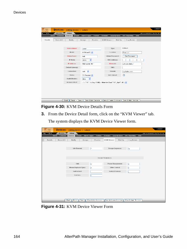
Devices
164 AlterPath Manager Installation, Configuration, and User’s Guide
Figure 4-30: KVM Device Details Form
3. From the Device Detail form, click on the “KVM Viewer” tab.
The system displays the KVM Device Viewer form.
Figure 4-31: KVM Device Viewer Form

Configuration and Administration 165
Devices
Table 4-15: Device KVM Viewer Form
Element Definition
KVM Viewer Tab that links to the KVM Viewer form (currently displayed).
Idle Timeout The time (in seconds) it takes before the KVM viewer switches to idle mode after a period of inactivity. Default value = 3
Escape Sequence The special character (keyboard key) to be used by the user to send a system command when using the KVM viewer or OSD. The “primary” escape sequence or key is combined with the various escape sequences that follow.
Default value = ^k
Escape Sequences:
Quit Closes the session to a port and takes you back to the KVM/net Main Menu.
Power Management Initiates a power control session.
Mouse/Keyboard Sync Resets the keyboard and mouse synchronization if either one becomes unavailable after adding a new server to the KVM/net.
Video Control Controls screen brightness and contrast.
Switch Next Switches from the currently connected server to the next server that you are authorized to access.
Switch Previous Switches from the currently connected server to the previous server.

Devices
166 AlterPath Manager Installation, Configuration, and User’s Guide
4. From the KVM Viewer form, make the necessary changes and then click on Save.
To Cascade a Secondary KVM to a Primary KVMThe Devices Detail form for a KVM allows you to add a secondary KVM to be cascaded (or connected) to a primary KVM switch.
Please refer to the KVM User Manual or the KVM/net User for more detailed information about cascading.
To connect a Secondary KVM to a Primary KVM switch, follow the steps below:
1. From the menu, select “Devices.”
The system displays the Device List form.
2. From the Device List form, select the “Edit” column of the KVM device you wish to configure.
The system displays the Device Detail form.
Port Info Displays any information about the current port.
Back Button to return to the previous form.
Reset Button to reset the input fields of the current form.
Save Button to save the configuration to Flash.
Save & List Cascade Displays the Cascade List form which shows a list of cascaded KVM devices, if configured.
Save & Create Consoles Button to initiate the Console Wizard.
Save & Auto Discover Button to initiate the Device Discovery Wizard.
Table 4-15: Device KVM Viewer Form (Continued)
Element Definition

Configuration and Administration 167
Devices
3. From the Device Detail form, click on the “Save & List Cascade” button.
The system displays the Device Cascade List form.
Figure 4-32: Device Cascade List Form
For a definition of the column fields, refer to the Field Definition table of the Cascade Detail form, next step.
4. To configure a new device for cascading, click the “Add” button.
Or, to edit an existing cascaded device, click on the “edit” link that corresponds to that device.
The system displays the Device Cascade Detail form:

Devices
168 AlterPath Manager Installation, Configuration, and User’s Guide
Figure 4-33: Device Cascade Detail Form
5. Complete the dialog box as follows: Table 4-16: Device Cascade Detail Form
Element Definition
Device Name Name of the secondary device or KVM switch.
Parent Name The name of the primary KVM switch to which you are connecting the secondary device or KVM switch.
Number of Ports Number of ports contained in the device to be cascaded.
Port Connected to User 2 The primary KVM/net port to be connected to the User 2 port of the cascaded KVM (or port B of a cascaded KVM Expander).

Configuration and Administration 169
Alarm Trigger
6. Click on “Save” to complete the configuration
Alarm TriggerNote: Alarm triggers work only with serial and IPMI consoles.
An alarm trigger is a text string that you can create to generate any one or combination of the following:
• Email notification for users or administrators• Alarm
There are five alarm trigger entries that already exist:
Figure 4-34:Pre Existing Alarm Triggers
Port Connected to User 1 The primary KVM/net port to be connected to the User 1 port of the cascaded KVM (or port A of a cascaded KVM Expander).
Table 4-16: Device Cascade Detail Form (Continued)
Element Definition

Alarm Trigger
170 AlterPath Manager Installation, Configuration, and User’s Guide
These alarm triggers are used in connection with the Health Monitor feature, the OTP feature, and the Heartbeat (fault tolerant) configuration features of the AlterPath Manager, which includes the monitoring of any modems configured. You can modify these alarm triggers, but you cannot delete them.
For pre existing triggers to work, you must enable alarm triggers using the Alarm Trigger details form.
Table 4-17: Pre-existing Alarm Trigger Entries
Alarm Trigger Default Expression/Explanation
Health Modem “HeaLth_MoDeM”
Health Monitor “HeaLth_MoNiToR”
OTP Alarm “OTP CoNnEctiOn”This alarm is triggered when a One Time Password connection is made. This only works with a dialout connection to an ACS with OTP enabled. See “One Time Password Configuration” on page 133.
Resources Take Over “remote resource transition completed” This alarm occurs after a failback completes (only appear in APM 2500 and APM 5000). See “Redundant (Fault Tolerant) Configuration” on page 261.
Take Over “mach_down takeover complete for node”This alarm occurs after a failover completes(only appear in APM 2500 and APM 5000). See “Redundant (Fault Tolerant) Configuration” on page 261.
Configuration and Administration 171
Alarm Trigger
Alarm Trigger ManagementUse the Alarm Trigger forms to perform the following Alarm Trigger management procedures:
Note: Users who use the application in Access Mode also have the capability to change their email address through the User’s Profile form.
To View the Alarm Trigger List FormThe Alarm Trigger List form allows you to view all the alarm triggers configured for the AlterPath Manager as well as to create, edit, and delete alarm triggers from the list.
To view the Alarm Trigger List form, follow the steps below:
Table 4-18: Forms Used to Configure Alarms
Form Function Form(s) Used
Add a new trigger string. Alarm Trigger list form (“Add” button) > Alarm Trigger detail form.
Edit an alarm trigger. Alarm Trigger list form (Alarm Trigger name) > Alarm Trigger detail form.
Delete an alarm trigger. Alarm Trigger list form (“Delete” button).
Create an alarm for the trigger string and prioritize the alarm.
Alarm Trigger detail form (Input fields: “Create Alarm” and “Priority”).
Create notification events (email list).
Alarm Trigger detail form (input field: “Notify”).
Assign one or more user to receive an email or alarm.
Console Detail form (Notify button). Go to: Consoles: Console List > Console Detail.
Define or verify the email that is used when a user is notified of an event.
User List form > User Detail form.

Alarm Trigger
172 AlterPath Manager Installation, Configuration, and User’s Guide
1. From the menu, select “Alarm Trigger.”
The system displays the Alarm Trigger List form.
Figure 4-35: Alarm Trigger List Form
For an explanation of each fieldname, refer to the Form Fields and Elements of the Alarm Trigger Definition form, next form section.
To view or edit the configuration of an alarm trigger, click on the alarm trigger name.
To Create an Alarm TriggerUse the Alarm Trigger Detail form to define triggers to generate user notifications and alarms.
To create an alarm trigger, follows the steps below:
1. From the menu, select “Alarm Trigger.”
The system displays the Alarm Trigger List form.
2. From the Alarm Trigger List form, click on the “Add” button.
The system displays the Alarm Trigger Detail form.

Configuration and Administration 173
Alarm Trigger
Figure 4-36: Alarm Trigger Detail Form
Table 4-19: Alarm Trigger Detail Form
Element Definition
Alarm Trigger Name Name of the trigger. Selecting a trigger name invokes the Alarm Trigger Detail form for that trigger.
Trigger Expression String used to generate a trigger.
Notify Yes or No. Indicates if system needs to notify (i.e., send an email to) the user.
Create Alarm Yes or No. Indicates if system needs to send an alarm to the user.
Priority Indicates the priority or severity level of the alarm.
Status Enable or disable a trigger.
Back Button to return to the previous page or form.

Alarm Trigger
174 AlterPath Manager Installation, Configuration, and User’s Guide
3. Complete the fields, as necessary.
4. Click the “Save” button to complete the procedure.
To Delete an Alarm Trigger1. From the main Alarm Trigger form, select the triggers to be deleted by
clicking the check boxes to the left of each Alarm Trigger name.
2. Click the “Delete” button.
Configuring Alarms for Device Health MonitoringTo enable the Device Health Monitoring feature of the AlterPath Manager, you must also configure its alarm trigger(s). As discussed in the Device Management section, this feature is designed to monitor devices on a periodic basis as well as to create log files, and to send an alarm notification to specified users. Users must have a valid email address as configured in the User Detail form (Users: User List > User Detail) to receive alarm notifications.
Configuration Requirement: Device Detail Form
For Health Monitoring to work, you must define the frequency of monitoring from the “Health Monitor” user entry field of the Device Detail form (Devices: Device List > Device Detail) as shown below:
Save Button to save your trigger entry.
Reset Button to reset the form to create a new trigger entry.
Table 4-19: Alarm Trigger Detail Form (Continued)
Element Definition

Configuration and Administration 175
Alarm Trigger
Figure 4-37: Health Monitor User Entry Field
The available choices from the “Health Monitoring” drop down list are:
Once defined, proceed to the Alarm Trigger Detail form to define the Health Monitoring Alarm Trigger.
Using the Logical AND in the Alarm Trigger ExpressionTo create a logical AND in the alarm trigger expression, use the period and asterisk: .*
Table 4-20: Health Monitor Frequency Selections
Selection Definition
Never System will never run Health Monitoring for this device (default).
Daily System will run Health Monitoring at 2 am everyday.
Weekly System will run Health Monitoring at 3 am every Saturday.
Monthly System will run Health Monitoring at 4 am on the first of each month.

Alarm Trigger
176 AlterPath Manager Installation, Configuration, and User’s Guide
The alarm trigger is also capable of processing substrings. OK, for example, is a substring of NOK. Therefore, both types of messages will cause alarms if.*OK is appended to the HeaLth_MoNiToR trigger string.
To Configure the Health Monitoring Alarm Trigger1. To configure an alarm trigger associated with Health Monitoring, go to
the Alarm Trigger Details form (Alarm Trigger List > Health Monitor.
Figure 4-38: Health Monitoring Alarm Trigger Detail Form
2. From the Alarm Trigger Definition form, complete the fields as follows: Table 4-21: Alarm Trigger Setup Fields
Element Definition
Alarm Trigger Name Provide a name to be associated with this particular alarm trigger.

Configuration and Administration 177
Alarm Trigger
How Health Monitoring WorksBased on the aforementioned configuration settings, the program gets from the database a list of devices to check. The monitoring results are ultimately stored in a log file using the following line format for each device:Device_Name,IP,Device_IP,Phone_Number,Date,Time, Result_Status
Each line is a syslog message generated by Health Monitoring, and contains the string identifier, HeaLth_MoNiToR which is used by the alarm trigger. Moreover, the “Result_Status” field will have two leading strings:
• “OK” (indicates that the device is okay)• “NOK” (indicates a problem)It is for this reason that the trigger expression needs to be restricted further to: HeaLth_MoNiToR.*NOK in order for users to get messages that only relate to failure, and not be bombarded by a large amount of unnecessary messages.
Trigger Expression Type in: HeaLth_MoNiToR
NOTE: To effectively filter the alarm trigger to generate only messages relating to failure, it is recommended that the Trigger Expression be restricted to: HeaLth_MoNiToR.*NOK (see explanation, next section).
Notify Select “Yes” if you want users to receive email notifications regarding the alarm.
Create Alarm Select Yes if you want alarms to be generated based on the trigger expression.
Priority Select a priority to be associated with the alarm.
Status Select Enable to enable this particular alarm trigger.
Table 4-21: Alarm Trigger Setup Fields (Continued)
Element Definition
Profiles
178 AlterPath Manager Installation, Configuration, and User’s Guide
User NotificationFor Health Monitor notification to work properly, you must add users to the “Notify Users” list associated with the device.
ProfilesThe “Profiles” option allows you to configure the port profile for a target console. Port profiles define a standard set of parameters that are common to many consoles such as port speed, data bits, and stop bits.
There is a default profile and there are other profiles which the Device Discovery feature can generate. You may want to define your own profile before adding consoles because it is more convenient, but you may also edit individual consoles to use a different profile at a later time.
The Profiles List form is shown below.
Table 4-22: Summary of Profiles Forms
Action Form(s) Used
Add a new profile. Profile list form (“Add” button) > Profile detail form.
Edit a profile. Profile list form (name link) > Profile detail form.
Delete a profile. Profile list form (“Delete” button).

Configuration and Administration 179
Profiles
Figure 4-39: Profiles List Form
To Add a New ProfileTo add a new profile, perform the following steps:
1. From the Profile List form, select the “Add” button.
The Profile Detail form appears:

Profiles
180 AlterPath Manager Installation, Configuration, and User’s Guide
Figure 4-40: Profile Detail Form Table 4-23: Profiles Detail Form
Element Definition
Profile Name Port name.
Console Type Drop down list to select type of console supported.
Description Brief description of the profile.
Status Port status (Enable or Disable).
Port Speed Serial port baud rate.
Port Data Size Number of data bits (7 or 8).
Port Stop Bits Number of stop bits (1 or 2).
Port Parity None, even, or odd.
Port Flow Flow control (none, hardware, or software).
DCD Sensitive How the console server responds to changes to DCD signal.

Configuration and Administration 181
Consoles
2. Enter your port settings and other profile information in the provided fields
3. Click “Save” to complete the configuration.
To Modify a ProfileTo edit a profile, perform the following steps:
1. From the Profile List form, select the profile you wish to edit.
The Profile Detail form appears.
2. From the Profiles Details form, make your changes.
3. Click “Save” to complete the configuration.
ConsolesNote: For console forms associated with the Blade Module, see “Blade Management Module” on page 225.
The “Consoles” option allows you to perform the following console management procedures:
Port Break Sequence As indicated.
Back / Save / Reset Buttons for the indicated actions.
Table 4-24: Summary of Console Forms
Action Form(s) Used
Add a new console to connect to the AlterPath Manager and for user access.
Consoles List > “Add” button > Select Console Type > Console detail.
Table 4-23: Profiles Detail Form (Continued)
Element Definition
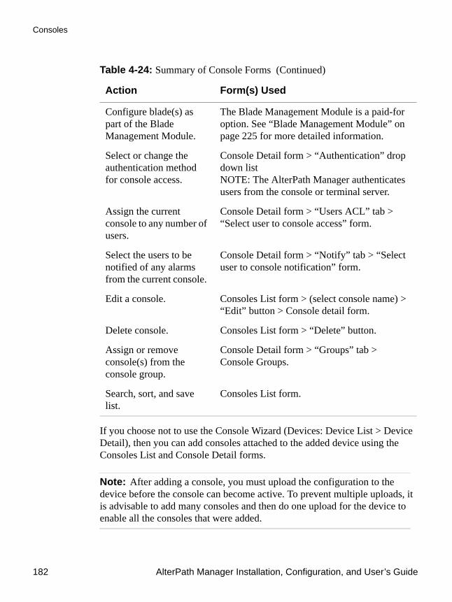
Consoles
182 AlterPath Manager Installation, Configuration, and User’s Guide
If you choose not to use the Console Wizard (Devices: Device List > Device Detail), then you can add consoles attached to the added device using the Consoles List and Console Detail forms.
Note: After adding a console, you must upload the configuration to the device before the console can become active. To prevent multiple uploads, it is advisable to add many consoles and then do one upload for the device to enable all the consoles that were added.
Configure blade(s) as part of the Blade Management Module.
The Blade Management Module is a paid-for option. See “Blade Management Module” on page 225 for more detailed information.
Select or change the authentication method for console access.
Console Detail form > “Authentication” drop down listNOTE: The AlterPath Manager authenticates users from the console or terminal server.
Assign the current console to any number of users.
Console Detail form > “Users ACL” tab > “Select user to console access” form.
Select the users to be notified of any alarms from the current console.
Console Detail form > “Notify” tab > “Select user to console notification” form.
Edit a console. Consoles List form > (select console name) > “Edit” button > Console detail form.
Delete console. Consoles List form > “Delete” button.
Assign or remove console(s) from the console group.
Console Detail form > “Groups” tab > Console Groups.
Search, sort, and save list.
Consoles List form.
Table 4-24: Summary of Console Forms (Continued)
Action Form(s) Used

Configuration and Administration 183
Consoles
Note: See “Difference between Auto Upload and Manual Upload” on page 143.
Data buffering, data logging, and event notification are valid definitions only for consoles with permanent connections (i.e., data status is enabled).
Limitation of Remote Authentications in ACS Console Access
To upload configurations and firmware, you must configure the ACS device to use “root” as the admin user. However, access to an ACS console as root through the AlterPath Manager is currently not possible if the ACS serial port is configured to use any remote only or remote-down/local authentication.
Note: In this case, remote means any of remote (nis), Tacacs Plus, Radius, ldap, etc.
There are two scenarios that you can use to work around this limitation:
1. If you want root as well as other admin users to have access to the ACS via the APM:
Configure ACS consoles for remote/local or local/remote access (local/radius, radius/local, local/TacacsPlus, TacacsPlus/local are the options available in this case).This allows firmware upgrades, and configuration upgrades. It also allows console access by root and other users with access.
2. If you want to configure remote only authentication or remote-down/local authentication (where remote can be any of the authentication protocols):
Configure the ACS device and consoles, using “root” as the admin user. Then upload the configuration (and firmware, if necessary) as root. Root is able to upload configuration and firmware to the ACS, but cannot access the ACS via the APM.
Next, configure the ACS device as the remote user. The remote user can access the ACS via the APM.
To View the Console ListTo view the Console List form, perform the following steps:

Consoles
184 AlterPath Manager Installation, Configuration, and User’s Guide
1. From the menu panel, select “Consoles.”
The system displays the Consoles List form:
Figure 4-41: Consoles List Form
From the Consoles List form, you can add, edit, or delete a console by selecting the appropriate button or link.
Note: For console forms associated with the Blade Management Module, see “Blade Management Module” on page 225.
Changing the Number of Consoles per PageYou can change or configure the number of consoles that you can view for each page. By default the number of consoles (or lines) per page is set to 512. If you want to change this setting go to “To Change the Number of Consoles per Page” on page 297.
To Add a Serial ConsoleThis procedure uses the serial console as an example of adding a new console. While there are variations to the Console Detail form based on the console type to be configured, there is a standard procedure for adding a console.
To add a console, follow the steps below:

Configuration and Administration 185
Consoles
1. From the menu, select “Consoles.”
The system displays the Consoles List form.
2. From the Consoles List form, click on the “Add” button.
The system displays the Creating New Console form:
Figure 4-42: Creating New Console Form
3. From the Creating New Console form, select the type of console you wish to add.
The system displays the Console Detail form:

Consoles
186 AlterPath Manager Installation, Configuration, and User’s Guide
Figure 4-43: Console Detail Form
Table 4-25: Consoles, Details Form
Field Meaning
Details Tab to display the Console Detail form which is the currently displayed form.
User ACL Tab to display the form used to assign or authorize users to access the current console.
Notify Tab to display the Console Notify form used to assign users to be notified when an alarm pertaining to the current console or device occurs.
Groups Tab to display the Select Console Group form used to assign the current console to one or more console groups.
Outlets Tab to display the form used to assign outlets if an IPDU is assigned and connected to the console.

Configuration and Administration 187
Consoles
Log Rotate Tab to display the Log Rotation form, used to set log rotation by configurable size or by selected time interval (available for ACS and TS devices and consoles as well as KVM devices).
Console Name Name of the console.
Device Name Drop down list to select the device to which the current console is connected.
Port Port on the device to which the console is connected.
NOTE: In the Blade Module, if you are adding a switch console, the Port number corresponds to the switch number (go to Devices > Switch 1 through 4).
Profile Name Name of port profile.
Description Brief description of the console.
Location Physical location of the console.
Machine Type Type of machine connected to the console.
Machine Name Name of machine connected to the console.
OS Type Type of operating system.
OS Version Version of operating system.
Connection Drop down list. Method used to establish a console connection: “ssh,” “telnet,” “raw data,” or “ssh_telnet”
Status Drop down list (Enable, Disable, OnDemand).
Table 4-25: Consoles, Details Form (Continued)
Field Meaning

Consoles
188 AlterPath Manager Installation, Configuration, and User’s Guide
4. Complete the Console Detail form, as necessary.
5. Click on “Save” to complete the procedure.
Console Type: KVMSelecting KVM as the Console Type displays the Console Detail form below. The Console Detail form for KVM allows you to configure the KVM ports for a KVM/net switch or KVM ports for an OnSite switch.
Authentication Drop down list to select the type of authentication for the AlterPath Manager to access the console port.
NNM Selection Name Network Node Management name to be used if you are configuring this port to be monitored by an HP OpenView server.
Remote Data Buffer
(0 to disable)
The size of the remote data buffer in bytes. Filling in this field enables remote data logging by ACS/TS.
Back Button to revert to the last page or form.
Save Button to save the configuration.
Table 4-25: Consoles, Details Form (Continued)
Field Meaning
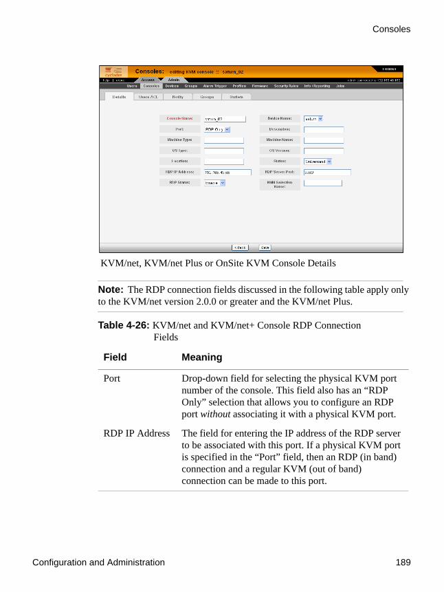
Configuration and Administration 189
Consoles
KVM/net, KVM/net Plus or OnSite KVM Console Details
Note: The RDP connection fields discussed in the following table apply only to the KVM/net version 2.0.0 or greater and the KVM/net Plus.
Table 4-26: KVM/net and KVM/net+ Console RDP Connection Fields
Field Meaning
Port Drop-down field for selecting the physical KVM port number of the console. This field also has an “RDP Only” selection that allows you to configure an RDP port without associating it with a physical KVM port.
RDP IP Address The field for entering the IP address of the RDP server to be associated with this port. If a physical KVM port is specified in the “Port” field, then an RDP (in band) connection and a regular KVM (out of band) connection can be made to this port.
Consoles
190 AlterPath Manager Installation, Configuration, and User’s Guide
When you configure a KVM/net or KVM/net Plus console, there is an option to configure an RDP connection. You must:
• The “RDP IP Address” field (must be a static IP address) • Set the “RDP Status” drop-down to “Enable” • In most cases, you can leave the “RDP Server Port” number setting at
3389 (default)
The following figure illustrates enabling RDP on the server connected to KVM port 2. When an attempt to connect to the port (KVM port 2 in this case) is made, the console viewer will attempt to launch the RDP viewer first by default. If the RDP connection is already in use, or cannot be made, a regular KVM connection will be attempted on KVM port 2.
RDP Server Port This field contains the RDP viewer port number associated with this console. The default of 3389 can be used in most cases.
RDP Status Drop-down field used to enable or disable the ability to make the RDP connection.
Table 4-26: KVM/net and KVM/net+ Console RDP Connection Fields (Continued)
Field Meaning

Configuration and Administration 191
Consoles
Figure 4-44:Enabling RDP on KVM/net or KVM/net Plus Console Port.
You can also configure a port as “RDP Only.” This allows the KVM/net Plus to connect exclusively to an RDP server over the Ethernet (in-band). For this type of configuration, a physical KVM port connection is not necessary. The following figure illustrates enabling an “RDP Only” connection.

Consoles
192 AlterPath Manager Installation, Configuration, and User’s Guide
Figure 4-45:Configuring or Editing an RDP Only Console
When configuring an “RDP Only” connection, you must configure the “RDP IP Address,” the “RDP Service Port” (default 3389), and you must select “RDP Only” from the “Port” pull-down field.
Caution: Be sure to turn off your web browser’s popup blocker before attempting to make an RDP connection. An RDP connection will fail if you have your browser’s popup blocker turned on.
To Select Users to Access the ConsoleUse the Console Users ACL form to assign and authorize one or more users to access the current console.
1. From the Console Detail form (Consoles: Console List > Console Detail), click on the “Users ACL” tab.
The system displays the Console Users ACL form:

Configuration and Administration 193
Consoles
Figure 4-46: KVM Console Users ACL Form
2. From the resulting form, select a user from the “Select User to Console Access” view panel.
In the selection box, “+USER” is the default list which contains all users. The plus (+) sign is also used to indicate all defined groups.
3. Select the “Add” button.
The system transfers the selected user to the “Selected Users” view panel on the right.
4. To select another user, repeat steps 1 and 2. You can also use the Shift key to select multiple users.
5. Click on “Save” to complete the procedure.
To Select Users to be NotifiedUse the Console Notify form to assign one or more users to whom the system can send all notifications (email or alarm) pertaining to the current console.
1. From the Console Detail form (Consoles: Console List > Console Detail), click on the “Notify” tab.
The system displays the KVM Console Notify form:

Consoles
194 AlterPath Manager Installation, Configuration, and User’s Guide
Figure 4-47: KVM Console Notify Form
2. From the resulting form, select a user from the “Select User to Notify” view panel.
In the selection box, “+USER” is the default list which contains all users. The plus (+) sign is also used to indicate all defined groups.
3. Select the “Add” button.
The system transfers the selected user to the “Selected Users” view panel on the right.
4. To select another user, repeat steps 1 and 2. You can also use the Shift key to select multiple users.
5. Click on “Save” to complete the procedure.
To Assign the Console to a GroupYou can assign the current console to one or more groups using the Console Groups form. To use this form, however, a console group must already exist. To create a new group, you must select “Groups” from the main menu.
To assign a console to a group, follow the steps below:
1. From the Console Detail form (Consoles: Console List > Console Detail), click on the “Groups” button.

Configuration and Administration 195
Consoles
The system displays the Console Groups form:
Figure 4-48: KVM Console Groups Form
2. From the resulting form, select a group from the “Select Console Groups” view panel.
Note: As with USER and DEVICE, CONSOLE is the default list which contains all consoles.
3. Select the “Add” button.
The system transfers the selected group to the “Selected Groups” view panel on the right.
4. To select another group, repeat steps 1 and 2. You can also use the Shift key to select multiple groups.
5. Click on “Save” to complete the procedure.
To Delete a Console from a GroupTo delete a Console from one or more groups, follow the steps below:
1. From the menu panel, select “Consoles.”
The system displays the Console List form.

Consoles
196 AlterPath Manager Installation, Configuration, and User’s Guide
2. Under the Config column of the Console List form, click on the “edit” link of the Console you wish to remove from a group.
The system displays the Console Detail form.
1. From the Console Detail form, click on the “Groups” tab.The system displays the Console Group form.
3. From the Selected Groups view panel of the Console Group form, select the group or groups from which you wish to remove the current console.
4. Click on the “Delete” button.
5. Click on “Save” to complete the procedure.
Deleting a Console GroupYou cannot delete a console group from the Console Group form. To delete a console group or any group, you must select “Groups” from the Admin menu.
See “Groups” on page 210.
To Connect to a ConsoleTo connect to a console using Secure Shell (SSH), follow the following step:
1. From the Console List form, select the console you wish to connect to by clicking on the console name.
2. Click on the “CLI Applet” button or the “CLI JWS” button.
Note: In the case of a KVM console, Click on the “KVM” button
Configuring OutletsThe “Outlets” tab allows you to associate the outlets on an IPDU to a console port.
On a KVM, the IPDU is connected to the KVM device’s “AUX” port, and outlets can be individually assigned to specific KVM ports.
On an ACS or TS device, the IPDU is connected directly to the serial console port. The outlets on the IPDU are accessed and controlled through the console port using the IPDU’s command line interface.

Configuration and Administration 197
Consoles
Log Rotate NowEither periodically, or when the log file reaches a specified size, the system creates a backup (rotation) file and then creates a new file to collect a new set of console data. The file rotation is seamless with no data loss as the system copies from one file to another.
As administrator, you have the options to manually compress and rotate the log file, archive it, and then open a new file to accept new logs.
Note: This does not apply to KVM consoles.
To Initiate Log Rotate (Manual Operation)To initiate the logrotation perform the following steps:
1. From the appropriate list form, click on the console name or device name, and then click the “EDIT” option.
The system displays the Detail form.2. From the Detail form, click the “Log Rotate” tab.
3. Click on the “Rotate Log NOW” button.
To Set Log Rotation in Auto ModeYou can also set the log rotation to be automatically performed on a daily, weekly, or monthly basis. To set the system to automatically initiate log rotation on a regular basis, perform the following steps:
1. From the appropriate list form, click on the console name or device name, and then click the “EDIT” option.
The system displays the Detail form.
2. From the Detail form, click the “Log Rotate” tab.
3. Choose one of the following radio buttons:
a. Rotate by frequency:Exception: file size > 2000 MBytes triggers auto rotation.
b. Rotate by file size (1-2000 Mbytes):

Consoles
198 AlterPath Manager Installation, Configuration, and User’s Guide
4. You can optionally select the checkbox to compress the log file after a rotation has taken place.
To Add an IPMI Console from Console Detail Form1. Open the Console List form (Consoles: Console List).
2. From the Console List form, click on the “Add” button.
3. The system opens the Adding Console form.
4. From the Adding Console form, select “IPMI” as the console type.
5. The system displays the IPMI Console Detail form.
6. Complete the fields, as necessary.
Use the Access Control List for Power to select users who can view the sensor display.
Note: IPMI is a paid-for option for AlterPath Manager users. The feature is hidden from users who do not need it.
To Activate IPMICopy the IPMI license file that you purchased from Cyclades into the following directory on your APM:
/var/apm/licenses/data/
Caution: Licenses (except for factory default licenses) must be reinstalled after you recreate the system partition or after you run the “installimg” command.
If you want to preserve your licenses before you recreate a system partition or before you run “installimg,” you can edit the file “/etc/files.list” and add your license file name to the list of files. Be sure to use the full path of each license file name you enter into this file. For example if the name of the license file you are adding is “APM_B_IPMI.enc” you should enter the full path name:/var/apm/licenses/data/APM_B_IPMI.encBe sure to follow up with the “saveconf” command. It is also a good idea to

Configuration and Administration 199
Users
save a copy of each license file on a server that can be accessed by your APM, just to be extra safe.
If at any time you run “defconf” the file, “/etc/files.list” will revert back to its original state, and you will need to reinstall your license.
UsersThe “Users” option provides forms that enable the following user management tasks: Table 4-27: Summary of User Forms
Action Form(s) Used
Add a new user. User list > “Add” button > User detail.
Authorize the current user to access one or more consoles.
User detail > “Access” tab > User Access form.
View or edit user information
User list > (username link) > User detail.
Set or change a user password.
User detail >“Set Password” button.
Define user as an administrator.
User detail > “Security tab” > “Select security rules” “ADMIN RULE” > “Add” button
Assign a user to one or more groups.
User detail > “Groups” tab > User Groups form.
Delete a user. User list > (select checkbox next to username) > “Delete” button.
Search, sort, and save list User list.
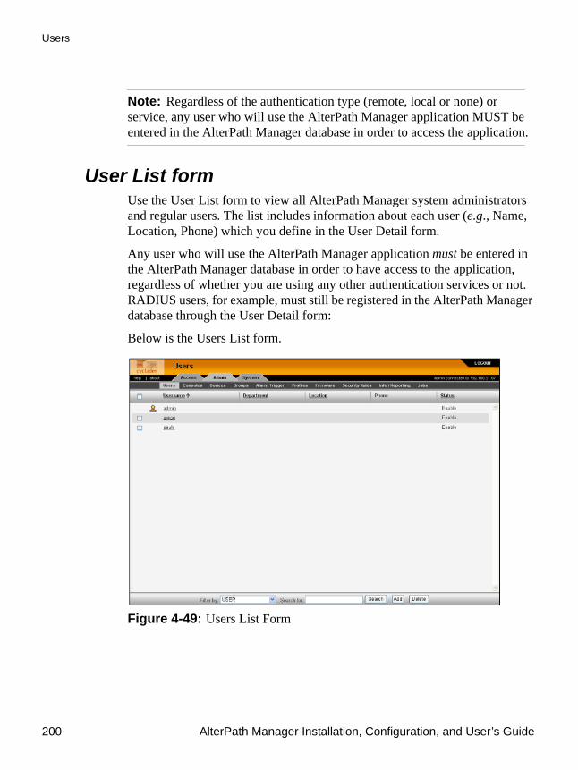
Users
200 AlterPath Manager Installation, Configuration, and User’s Guide
Note: Regardless of the authentication type (remote, local or none) or service, any user who will use the AlterPath Manager application MUST be entered in the AlterPath Manager database in order to access the application.
User List formUse the User List form to view all AlterPath Manager system administrators and regular users. The list includes information about each user (e.g., Name, Location, Phone) which you define in the User Detail form.
Any user who will use the AlterPath Manager application must be entered in the AlterPath Manager database in order to have access to the application, regardless of whether you are using any other authentication services or not. RADIUS users, for example, must still be registered in the AlterPath Manager database through the User Detail form:
Below is the Users List form.
Figure 4-49: Users List Form
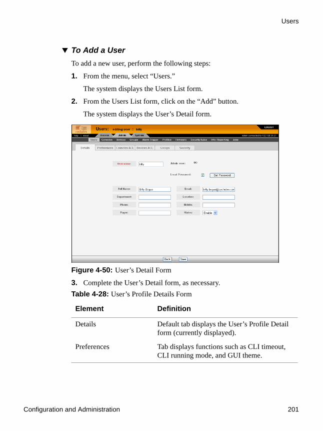
Configuration and Administration 201
Users
To Add a UserTo add a new user, perform the following steps:
1. From the menu, select “Users.”
The system displays the Users List form.
2. From the Users List form, click on the “Add” button.
The system displays the User’s Detail form.
Figure 4-50: User’s Detail Form
3. Complete the User’s Detail form, as necessary. Table 4-28: User’s Profile Details Form
Element Definition
Details Default tab displays the User’s Profile Detail form (currently displayed).
Preferences Tab displays functions such as CLI timeout, CLI running mode, and GUI theme.

Users
202 AlterPath Manager Installation, Configuration, and User’s Guide
Consoles ACL Consoles access control list (ACL) for the current user. Tab displays the selected consoles assigned to the current user and the consoles accessed by the user through group association.
Devices ACL Devices access control list (ACL) for the current user. Tab displays the selected devices assigned to the current user and the devices accessed by the user through group association.
Groups Tab to display the User’s Profile Group form which shows all groups to which the current user belongs.
Security Tab to display the security rule or rules assigned to the current user. The built in security rules are “DEFAULT RULE” and “ADMIN RULE.”
User Name The user name used to log into the AlterPath Manager.
Admin User If “YES,” indicates that the user has Admin privileges, and also belongs to the Admin user group.
Table 4-28: User’s Profile Details Form (Continued)
Element Definition

Configuration and Administration 203
Users
Security Rule
See the “User’s Detail Form” on page 201.
(For Admin use only)
Check box to indicate that a security rule has been assigned to the user. Designed to prevent admin users from locking themselves out, the check box is available only to admin users.
NOTE: In case the admin user is locked out when this check box is selected, the admin user can edit the script file:/var/apm/bin/apm_unlock_admin.sh from the Linux shell through the Serial Console Interface.
Local Password Check box to indicate that local authentication applies to the user. If this box is checked, the “Set Password” button becomes active.
Set Password Button that launches a password setup dialog box.
Full Name User’s full name.
Email User’s email. This is the same field name used by the system for event notification.
Department User’s department.
Location User’s Location.
Phone User’s phone number.
Mobile User’s mobile phone number.
Pager User’s pager number.
Status Indicates whether the user’s access is enabled or disabled.
Save Button to save the user’s configuration changes.
Table 4-28: User’s Profile Details Form (Continued)
Element Definition

Users
204 AlterPath Manager Installation, Configuration, and User’s Guide
4. Click on “Save” to complete the procedure, or continue to the “Preferences” tab.
To Configure User PreferencesThe User Preferences form allows you to configure features such as the type of CLI applet used, and color theme associated with the user. The user also has his or her own control of the parameters in the User Preferences form.
To configure user preferences, follow the steps below:
1. From the users’ profile “Details” form, click on the “Preferences” tab.
The system displays the users’ “Preferences” form:
Figure 4-51:User’s Preferences Form
2. Choose any of the following parameters to configure:
a. CLI timeout: on or off
b. CLI running mode: Applet, Java Web Start, or both
c. Reset Layout: Sets CLI terminal emulator settings to the default settings

Configuration and Administration 205
Users
d. GUI Theme: Select blue, gray, green, orange, or custom (from palette, or hexadecimal representation of RGB settings)
3. Click the “Save” button, or continue to the “Consoles ACL” tab.
To Select Consoles ACL for a UserThe Consoles ACL form allows you to assign one or more consoles for the current user.
To assign consoles to a user, follow the steps below:
1. From the “Preferences” form, click on the “Consoles ACL” tab.
The system displays the Console Access Control List (ACL) form:
Figure 4-52: User Consoles ACL Form
2. From the resulting form, select from the “Select Console to User Access” view panel the console you wish to assign to the user.
In the selection box, the plus (+) sign is used to indicate defined groups. The Console (or +CONSOLE) group is the default console group.
3. Click on the “Add” button.
The system transfers the selected group to the “Selected Consoles” view panel on the right.

Users
206 AlterPath Manager Installation, Configuration, and User’s Guide
4. To select another console, repeat steps 2 and 3. You can also use the “Shift” key to select multiple groups.
5. Click on “Save” to complete the procedure, or continue to the “Devices ACL” tab.
To Select Devices ACL for a UserThe Devices ACL form allows you to assign one or more consoles for the current user.
To assign devices to a user, follow the steps below:
1. From the “Consoles ACL” form, click on the “Devices ACL” tab.
The system displays the Devices Access Control List (ACL) form:
Figure 4-53:User Devices ACL Form
2. From the resulting form, select from the “Select Device to User Access” view panel the console you wish to assign to the user.
In the selection box, the plus (+) sign is used to indicate defined groups. The Device (or +DEVICE) group is the default device group.
3. Click on the “Add” button.
The system transfers the selected group to the “Selected Devices” view panel on the right.

Configuration and Administration 207
Users
4. To select another device, repeat steps 2 and 3. You can also use the “Shift” key to select multiple groups.
5. Click on “Save” to complete the procedure, or continue to the “Groups tab.
To Select User Groups for a UserThe User Group form allows you to assign a user to one or more user groups. The user group, however, must already exist to be able to assign a user to the user group. Otherwise, select “Groups” from the menu to create a user group.
To assign a user to one or more groups, follow the steps below:
1. From the “Devices ACL” form, click on the “Groups” tab.
The system displays the User Groups form.
Figure 4-54: User Groups Form
2. From the resulting form, select from the “Select Groups for the User” view panel the group you wish to assign to the user.
3. Select the “Add” button.
The system transfers the selected group to the “Selected Groups” view panel on the right.
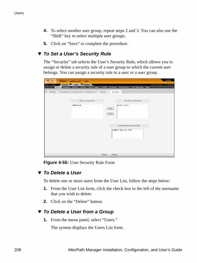
Users
208 AlterPath Manager Installation, Configuration, and User’s Guide
4. To select another user group, repeat steps 2 and 3. You can also use the “Shift” key to select multiple user groups.
5. Click on “Save” to complete the procedure.
To Set a User’s Security RuleThe “Security” tab selects the User’s Security Rule, which allows you to assign or delete a security rule of a user group to which the current user belongs. You can assign a security rule to a user or a user group.
Figure 4-55: User Security Rule Form
To Delete a UserTo delete one or more users from the User List, follow the steps below:
1. From the User List form, click the check box to the left of the username that you wish to delete.
2. Click on the “Delete” button.
To Delete a User from a Group1. From the menu panel, select “Users.”
The system displays the Users List form.
Configuration and Administration 209
Users
2. From the Users List form, click on the user name you wish to remove from a group.
The system displays the User Detail form for the selected user.
3. From the User Detail form, click on the “Groups” tab.
The system displays the User Group form.
4. From the “Selected Groups” view panel of the User Group form, select the group or groups from which you wish to remove the current user.
5. Click on the “Delete” button.
6. Click on the “Save” button to end the procedure.
Deleting a User GroupYou cannot delete a user group from the User Group form.
See “Groups” on page 210.
Local PasswordYou can set up users to have local authentication by setting the Local Password, and defining the user name and password.
A local password is used if the authentication setting for the AlterPath Manager is “Local.” The local password is also used as a backup when server-based authentication is being used. In this case, if the authentication server is unavailable due to network problems then the system can use the local password. It is therefore advisable that you set a local password for some users even when server-based authentication is being used.
To Configure the Local PasswordTo set up local authentication for a user, follow the following steps:
1. From the Users List form, select the user for whom you will set a password.
The system will bring up the definition form for that user.
2. If a password has not been set up, from the User Details form, select set password.

Groups
210 AlterPath Manager Installation, Configuration, and User’s Guide
System brings up the Password dialog box.
3. From the password dialog box, enter the password twice, and then click the “Submit” button.
4. From the User Details form, click on the “Local Password” check box.
5. From the User Details form, click the “Save” button.
GroupsThe “Groups” option allows you to create new groups of users, consoles, or devices, as well as to edit or delete these groups. The AlterPath Manager has three default groups:
• Device, • Console• User
The system does not allow you to edit or delete these groups. You can edit and delete only those groups that you have created.
While you can assign devices, consoles, and users to groups using their respective menu options (Devices, Consoles, and Users), it is only through the “Groups” menu option that you can create groups.

Configuration and Administration 211
Groups
Figure 4-56: Groups List Form
To Create a GroupTo create a new group, follows the steps below:
1. From the menu, select “Groups.”
The system displays the Groups List form (Figure 4-56).
2. From the Groups List form, click on the “Add” button.
The system displays the Adding Group form:

Groups
212 AlterPath Manager Installation, Configuration, and User’s Guide
Figure 4-57: Adding Group Form
3. From the resulting form, select the group type you wish to create (Device, Console, or User).
Based on your selection, the system displays the Group Detail form. The example below uses the Group General form for the Group Type, User.
Figure 4-58: New User Group General Form

Configuration and Administration 213
Groups
4. Enter the Group Name, Description, and Status of the new group.
5. Select desired members from the “Select group members” list box.
6. Click on the “Add” button.
7. Click on the “Save” button to complete the procedure.
To Add Members to a GroupTo add members to an existing group, follow the steps below:
1. From the menu, select “Groups.”
2. From the resulting Groups List form, select the type of group you want to configure.
3. From the resulting Group Details form, choose from the left list box the members you wish to add to the group.
4. Click on the “Save” button.
To Delete a Group
Note: You cannot delete the following system-generated default groups: Device, Console, and User.
To delete a group, follow the steps below:
1. From the menu, select “Groups.”
The system displays the Groups List form.
2. From the Groups List form, click on the checkbox of the group that you wish to delete.
3. Click on the “Delete” button.
To Assign a Security Rule to a User Group
Note: The “User” group includes an additional tab, “Security,” which allows you to assign one or more security rules to the current user group.
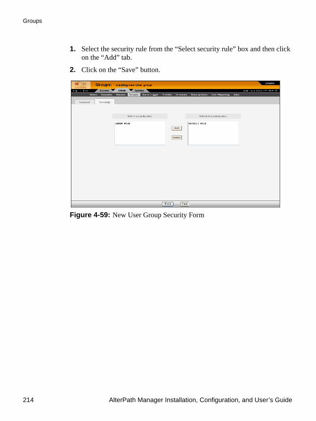
Groups
214 AlterPath Manager Installation, Configuration, and User’s Guide
1. Select the security rule from the “Select security rule” box and then click on the “Add” tab.
2. Click on the “Save” button.
Figure 4-59: New User Group Security Form

Configuration and Administration 215
Firmware
FirmwareAlterPath Manager contains a firmware repository and supports firmware upgrades for the TS, the ACS and the KVM/net. Each time a new firmware is released for the ACS and TS, Cyclades will release a package for AlterPath Manager to import.
The package contains firmware, boot code, release notes, user manual and dependency file. The dependency file is used to ensure you do not load the firmware to the wrong device or perform invalid upgrade operations.
The Firmware form provides a management tool for you to:
• Import firmware updates• Keep track of firmware updates• Document any comments regarding the particular firmware• Access manuals and release notes
Firmware Management consists of two forms:
• Firmware List form• Firmware Detail form. Any firmware that you add to the Firmware List form is also reflected in the “Firmware/Boot” pull-down list that appears in the Device Detail form. The next time you create a new device, the system will prompt you to upload the new firmware, as necessary.
The last part of this section provides instructions on how to upgrade the AlterPath Manager firmware.
Firmware List FormYou use the Firmware List form to open the Firmware Definition form, and to add or delete firmware.

Firmware
216 AlterPath Manager Installation, Configuration, and User’s Guide
Figure 4-60: Firmware List Form
For an explanation of each form field, refer to Table 4-29 on page 218.
To Add Firmware
Note: Firmware files (.tgz) are normally downloaded from the web and copied into the AlterPath Manager via Secure Copy (SCP). To add or import new firmware, follow this procedure:
1. From the web (www.cyclades.com), download the firmware to your computer.
2. Using the Linux shell on the serial console interface, use the SSH scp command to copy the firmware to AlterPath Manager.
Example: scp v214.tgz root@<ip_address>:/usr/fw
3. Open the Firmware List form and click the “Import” button.
The system will add the new firmware to the Firmware List form. The system also updates the “Firmware/Boot” pull-down list in the Device Details form.

Configuration and Administration 217
Firmware
To Delete Firmware1. From the menu panel, select “Firmware.”
2. From the Firmware List form, select the checkmark box of the firmware you wish to delete.
3. Select the “Delete” button.
To Upload Firmware to Console Devices1. From the Device Details form (Device List > “edit” button), select the
firmware you wish to upload from the “Firmware/Boot” pull-down list.
2. Click the “Save” button.
3. Go back to the Device List form and select the device(s) that need to be uploaded, and then click the “Upload” button.
4. Select “Upload firmware/bootcode” and/or “Upload configuration” (you have the choice to select either firmware, or configuration, or both).
Note: When uploading KVM/net or KVM/net Plus firmware, you should check the “Configuration” checkbox as well as the “Firmware/bootcode” checkbox, even if the current configuration had previously been uploaded. Otherwise you will get an indication in the device list that a configuration upload is required.
Caution: When uploading KVM/net or KVM/net Plus firmware, if any components are missing from the tgz file, the firmware upload attempt will fail.
5. Click the “Submit” button.
Note: The “Upload firmware/bootcode” option appears even if the AlterPath Manager firmware repository is empty. If you click on it, you must wait for a while before a message appears to let you know that the firmware repository is empty.

Firmware
218 AlterPath Manager Installation, Configuration, and User’s Guide
Firmware Detail FormUse the Firmware Detail form to:
• View firmware details• Add comments regarding a firmware.• Assign a status to a firmware• Access Manuals and Release Notes
Figure 4-61:Firmware Detail Form
The table below defines all the fields in the Firmware Detail form. Table 4-29: Firmware Detail Form
Element Function
Model Model number of the device(s) supported by the firmware.
FW Version Firmware version.
Release Date Release date of the firmware.
Boot Code Version Type of bootcode and version number.

Configuration and Administration 219
Firmware
To View and Access Firmware Information1. From the Firmware List form, select the particular Firmware Version you
wish to view.
The form brings up the Firmware Details form. From the Firmware Details form, you can do any of the following:
2. To access firmware documentation, select “Manual.”
3. To access Release Notes for the current firmware, select “Release Notes.”
4. Type in notes in the “Comments” input text box and then select “Save” to enter notes and comments about the current firmware.
5. If needed, enter the status (Enable or Disable) of the firmware installation or update.
To Upgrade the AlterPath Manager FirmwareYou may upgrade the AlterPath Manager firmware by downloading the upgraded software from the web to the AlterPath Manager.
HW Revision Hardware tied to the firmware version.
Manual Version As indicated.
Manual A link that launches the PDF version of the manual
FW Dependency As indicated.
Release Notes A link that launches a browser window with the release notes associated with the firmware.
Comments A scrollable field that contains notes of hardware and software dependencies
Status Indicates “Enable” or “Disable” status.
Table 4-29: Firmware Detail Form (Continued)
Element Function

Firmware
220 AlterPath Manager Installation, Configuration, and User’s Guide
1. From the Cyclades website (www.cyclades.com), download and copy the firmware to the AlterPath Manager via Secure Copy (SCP).
The firmware is composed of two files:
• all_<APM_model>_v141.tgz• all_<APM_model>_v141.tgz.md5sum
Copy the two files to the AlterPath Manager /tmp directory as follows: scp all_e2000_v141.tgz root@<APM_IP>:/tmp Enter scp all_e2000_v141.md5sum.tgz root@<APM_IP>:/tmp Enter
2. Log in to the AlterPath Manager as root, and then change the directory to /tmp as follows:
ssh root@<APM_IP> Enter cd /tmp Enter
Note: If you log in as shown here, you will lose the ssh connection after you reboot as indicated in step 4 below. You will either need to re establish the ssh connection after the APM finishes rebooting.
As an alternative, or you can log in to the APM by connecting a terminal directly to the APM console port. The terminal or terminal emulator should be set to 9600 bps, 8 bits, no parity, 1 stop bit, and no flow control. This will keep an active connection even while the APM reboots.
3. Install the new software to compact flash as follows: installimg all all_e2000_v141.tgz Enter
The system performs an MD5 checksum comparison and displays the message:
Checking all image . . .
If the firmware file is verified, the following is displayed:IMG OK

Configuration and Administration 221
Backing Up User Data
Note: If the firmware verification fails, you must restart this procedure from step 1.
4. Reboot the system as follows:
reboot Enter
Backing Up User DataUsing the serial console interface, you can back up and restore the configuration and data files of the AlterPath Manager to a local or a remote destination. This feature allows you to backup and restore (either independently or altogether) the following data types:
The command syntax for backup and restore are as follows (as shown in the command help):
/sbin/backup (log | sys[tem] | conf[figuration] | all) [user@host:|file
/sbin/restore (log | sys[tem] | conf[figuration] | all) [user@host:|file
Backup and Restore ScenariosFor illustration purposes, here are two scenarios in which you might perform a backup:
• Replicating data to a hot spare machine - You back up the configuration data and data buffers (logs) and restore them to a second AlterPath Manager unit. This method enables you to keep the network identity of
Table 4-30: APM Data Types
Data Type Definition
System Configuration Data related to the AlterPath Manager host settings such as IP Address, Authentication Type, and Host Name.
Configuration Data Data related to the configuration of consoles, users and so forth, which are stored in the database.
Logs The ASCII data collected from the consoles.

System Recovery Guidelines
222 AlterPath Manager Installation, Configuration, and User’s Guide
each AlterPath Manager unit, but maintain the same configuration for both units. The second unit serves as a spare system.
• Replacing the existing AlterPath Manager - You back up ALL data to an external server. The AlterPath Manager is then replaced with a new unit to which all data is restored. The new unit will have the same configuration as the original unit.
To use the Backup and Restore commands in the serial console interface, please refer to Chapter 5, “Advanced Configuration.
System Recovery GuidelinesIn the event that the AlterPath Manager goes down, the system will check the integrity of the file system during the restart. If a problem is found, then the system will attempt to repair any damage that may have occurred.
When performing a recovery procedure, if there is too much damage, you have the option to stop the booting process and take recovery actions through the serial console as follows:
1. Rebuild all partitions
2. Rebuild system partition
3. Rebuild database
4. Rebuild data log partition
The rest of the configuration process is done through the GUI/web interface.
APM Database Transaction SupportThe AlterPath Manager commits all successful database transactions to the AlterPath Manager database. To ensure data integrity, the AlterPath Manager will roll back any failed database transaction in the event that:
• There are concurrent users updating the same record at the same time or• A system fault caused the database transaction to fail.

Configuration and Administration 223
Info / Reporting
When multiple users who are logged in as admin update the same record simultaneously, the system will generate a warning message to one of the users.
To Respond to the Warning MessageWhen you receive the above warning message, you must perform the following steps:
1. Click on the “Reload” button located at the bottom of the screen.
The system displays the form that you were updating.
2. Verify the information to determine if you still need to update the form. If you need to update the form, then proceed to re-update the form and then click on the “Save” button.
Optimistic locking is a mechanism to lock objects in multi-user systems to preserve integrity of changes so that one person’s changes do not accidently get overwritten by another. It offers reduced concurrency, higher performance, and avoids deadlocks.
Changing the Default ConfigurationThis configuration procedure is for advanced users only. To change the default database configuration of the AlterPath Manager, please refer to Chapter 5, “Advanced Configuration.”
Info / ReportingInfo/Reporting is a list that summarizes all console access information by users and administrators.
This record has been updated by another user. The changes you made will not be saved. Please reload and edit again.

Info / Reporting
224 AlterPath Manager Installation, Configuration, and User’s Guide
Figure 4-62:Info / Reporting List FormTable 4-31: Info / Reporting List Form
Element Definition
User Name of session user. To sort by User, click on the “User” column heading.
Session Start Date and time when the session started. To sort by Session Start, click on the “Session Start” column heading. Down arrow indicates that the list is in descending order; up arrow, in ascending order.
Session End Date and time when the session ended.
Action The user’s action or the system action generated by the user. To sort by Action, click on the “Action” column heading.
Connect Type Connection type used by the session.
Source IP The source IP address used.
Next>> Button to view the next page.

Configuration and Administration 225
Blade Management Module
Info / Reporting DetailsTo view a more detailed information about a particular user from a detail line, select from under the “User” column the particular user you wish to view.
When you select a user from the Info/Reporting List form, the system displays the following detail list:
Figure 4-63: Info / Reporting Detail List
Blade Management ModuleThe Blade Module is an optional, paid-for, plug-in feature that enables the AlterPath Manager to provide console management of chassis, blades and switches. Once configured, the module allows authorized users to remotely manage the blades by providing access to the remote console and remote disk of a blade server.
<<Back Button to return to the previous page.
Table 4-31: Info / Reporting List Form (Continued)
Element Definition

Blade Management Module
226 AlterPath Manager Installation, Configuration, and User’s Guide
All blades provide authorized users with Command Line Interface (CLI), KVM/IP, virtual media, and power options. Like most devices supported by the AlterPath Manager, alarm notification, continuous logging, group and user management are integrated into the module. For security, blade users are controlled by the Control Access List (ACL) which is configured through the Security Rules settings.
The Blade Module also comes with a Blade Wizard which enables the admin user to configure up to 14 blades and 4 switches for each chassis. There is no limit to the number of chassis that the Blade Module can support.
To Activate the Blade Module1. Log onto your APM through the serial console interface as root.
2. Copy your Blade Module license file, using the following command and directory path:# cp APM_B_IBMBLADEMODULE.enc /var/apm/licenses/data/
3. Run the following command:# /etc/init.d/tomcat restart

Configuration and Administration 227
Blade Management Module
Forms Used to Configure the Blade ModuleThe Blade Module in Admin mode comprises the following forms: Table 4-32: Summary of Blade Module Forms
Menu Option Forms and their Functions
Devices Devices List - View list of chassis; add, edit or delete chassis; view logs.
Device Details - Edit chassis configuration details; set or change admin password; run blade wizard.
Groups - Select the group(s) to access the chassis.
Proxies - Select the type of web proxy to use when accessing the Blade Center Management Module.
Switch 1 - Configure a switch for the chassis.
Switch 2 - Configure a second switch for the chassis.
Switch 3 - Configure a third switch for the chassis.
Switch 4 - Configure a fourth switch for the chassis.
Consoles Consoles List - View list of blades/switches; add, edit or delete blades/switches.
Console Details - View or edit blade configuration details (e.g., connection type, log rotation, etc.)
Access - Select user(s) to access the current blade.
Notify - Select user(s) to be notified of an alarm regarding the current blade.
Groups - Select blade groups.
Alarm Triggers Alarm Trigger List - View alarm trigger list; add, edit or delete an alarm trigger.
Alarm Detail - View or configure a selected alarm trigger.
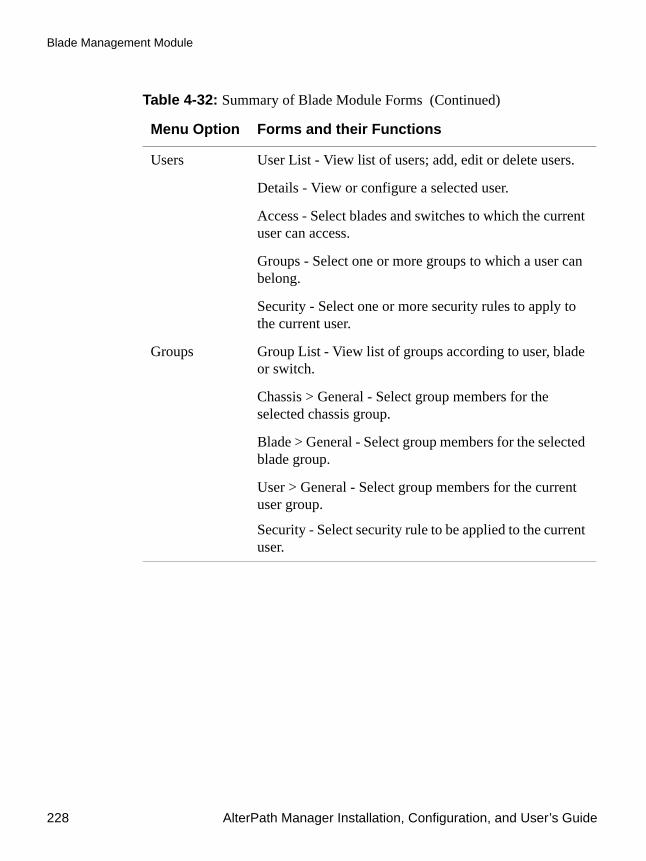
Blade Management Module
228 AlterPath Manager Installation, Configuration, and User’s Guide
Users User List - View list of users; add, edit or delete users.
Details - View or configure a selected user.
Access - Select blades and switches to which the current user can access.
Groups - Select one or more groups to which a user can belong.
Security - Select one or more security rules to apply to the current user.
Groups Group List - View list of groups according to user, blade or switch.
Chassis > General - Select group members for the selected chassis group.
Blade > General - Select group members for the selected blade group.
User > General - Select group members for the current user group.
Security - Select security rule to be applied to the current user.
Table 4-32: Summary of Blade Module Forms (Continued)
Menu Option Forms and their Functions

Configuration and Administration 229
Blade Management Module
Note: In Access Mode, a regular user can only view an individual blade/switch detail information from the Devices List form, but can not perform any add, delete, or edit functions. See Chapter 3, “User Level Web Access” for more detailed information about the BladeManager web interface in Access Mode.
Security Rule Security Rule List - View list of security rules; add, edit or delete a security rule.
General - Enable or disable the current security rule.
Source IP - Define the source IP addresses allowed or not allowed.
VLAN/Subnet - Define the VLANs/subnets allowed or not allowed.
Date/Time - Define the date and time in which system access is allowed or not allowed.
Authorization - Select the types of action allowable for the current security rule.
Info Reporting Info / Reporting List
Detail
Table 4-32: Summary of Blade Module Forms (Continued)
Menu Option Forms and their Functions

Blade Management Module
230 AlterPath Manager Installation, Configuration, and User’s Guide
DevicesThe Devices List form allows you to perform the following:
• Connect to the Blade Management Module Web GUI through a web proxy of the native web interface or by telnet access (or whatever default session type is configured from the Devices Detail form).
• Access add/edit forms (Details, Groups, Proxies, Switch 1 through 4) to add/edit chassis.
• Delete a blade chassis.• Run the Blade Wizard (to automatically create and configure the blades/
switches for the currently selected chassis.• View chassis access log.
To Add or Edit the Chassis1. From the menu, select “Devices.”
The system displays the Devices List form.
2. Perform one of the following steps:
a. If you are adding a new chassis, from the Devices List form, select the “Add” button.
The Select Device Type form appears; from this form, select “IBM Blade Center.”
b. If you are editing an existing chassis, from the Device List form, select the chassis you want to edit, and then click on the “edit” link that corresponds with the Blade chassis you are editing.

Configuration and Administration 231
Blade Management Module
Figure 4-64: Selecting “Blade_Center” from Devices List
The system displays the Devices detail form:
Figure 4-65: Blade Device Details Form

Blade Management Module
232 AlterPath Manager Installation, Configuration, and User’s Guide
3. Complete or modify the Details tabbed form as defined by the following table:
Table 4-33: BladeModule: Devices, Details Form
Element Definition
Device Name The symbolic name linked to the chassis. This is a required field
Type IBM Blade Center is the only supported type of device or chassis.
Location Physical location of the device or chassis.
Status Dropdown list box to select:
Enable - connection between the AlterPath Manager and the device is ALWAYS established.
Disable - no connection is established, and all child consoles follow this configuration.
OnDemand - connection is established only upon user’s request.
Admin Name The admin username (superuser) of the device. This is a required field.
Admin Password Button to invoke a dialog box used to define the Admin’s password. This password is used to access the IBM Blade Center port, but NOT to change the password. You must enter the SAME password that is registered in the blade server.
IP Mode Dropdown list box. Select “int_dhcp” if APM AlterPath Manager is the DHCP server for this device, or “static” if using a static IP.
See “Configuring Your DHCP Server” on page 142.”
Mac Address Specify the MAC address if the selected IP mode is int_dhcp.

Configuration and Administration 233
Blade Management Module
4. Click on the “Save” button, and proceed to the next tab, as necessary.
To Select a Group to Access the ChassisThe “Groups” tabbed form allows you to specify one or more groups to access the currently selected chassis. To configure Groups, perform the following steps:
1. From the menu, go to Devices (click on the “Add” button or the “edit” link) > Details > Groups.
The system displays the Device Groups form.
IP Address The IP address of the device for IP mode: “int_dhcp” or “static.”
Netmask As indicated, in dotted notation.
Default Gateway As indicated, in dotted notation.
DNS As indicated, in dotted notation.
Connection Select “telnet” or “ssh.”
Back Button to return to the previous page.
Reset Button to reset the form.
Save Button to save your configuration.
Save & Create Blades Button to activate the Blade Wizard.
Table 4-33: BladeModule: Devices, Details Form (Continued)
Element Definition
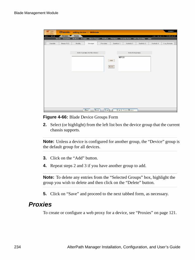
Blade Management Module
234 AlterPath Manager Installation, Configuration, and User’s Guide
Figure 4-66: Blade Device Groups Form
2. Select (or highlight) from the left list box the device group that the current chassis supports.
Note: Unless a device is configured for another group, the “Device” group is the default group for all devices.
3. Click on the “Add” button.
4. Repeat steps 2 and 3 if you have another group to add.
Note: To delete any entries from the “Selected Groups” box, highlight the group you wish to delete and then click on the “Delete” button.
5. Click on “Save” and proceed to the next tabbed form, as necessary.
ProxiesTo create or configure a web proxy for a device, see “Proxies” on page 121.
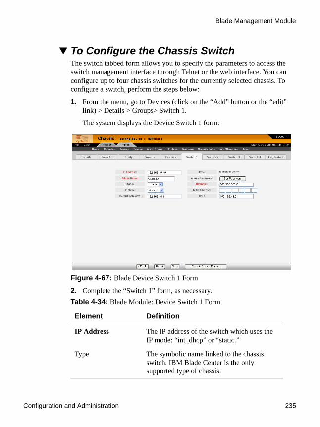
Configuration and Administration 235
Blade Management Module
To Configure the Chassis SwitchThe switch tabbed form allows you to specify the parameters to access the switch management interface through Telnet or the web interface. You can configure up to four chassis switches for the currently selected chassis. To configure a switch, perform the steps below:
1. From the menu, go to Devices (click on the “Add” button or the “edit” link) > Details > Groups> Switch 1.
The system displays the Device Switch 1 form:
Figure 4-67: Blade Device Switch 1 Form
2. Complete the “Switch 1” form, as necessary. Table 4-34: Blade Module: Device Switch 1 Form
Element Definition
IP Address The IP address of the switch which uses the IP mode: “int_dhcp” or “static.”
Type The symbolic name linked to the chassis switch. IBM Blade Center is the only supported type of chassis.
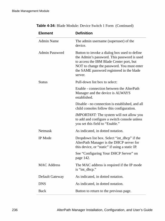
Blade Management Module
236 AlterPath Manager Installation, Configuration, and User’s Guide
Admin Name The admin username (superuser) of the device.
Admin Password Button to invoke a dialog box used to define the Admin’s password. This password is used to access the IBM Blade Center port, but NOT to change the password. You must enter the SAME password registered in the blade server.
Status Pull-down list box to select:
Enable - connection between the AlterPath Manager and the device is ALWAYS established.
Disable - no connection is established, and all child consoles follow this configuration.
IMPORTANT: The system will not allow you to add and configure a switch console unless you set this field to “Enable.”
Netmask As indicated, in dotted notation.
IP Mode Dropdown list box. Select “int_dhcp” if the AlterPath Manager is the DHCP server for this device, or “static” if using a static IP.
See “Configuring Your DHCP Server” on page 142.
MAC Address The MAC address is required if the IP mode is “int_dhcp.”
Default Gateway As indicated, in dotted notation.
DNS As indicated, in dotted notation.
Back Button to return to the previous page.
Table 4-34: Blade Module: Device Switch 1 Form (Continued)
Element Definition

Configuration and Administration 237
Blade Management Module
3. Click on “Save” to save your configuration.
4. To configure another switch, click on the next Switch tab form.
Two Methods of Blade ConfigurationOnce the chassis has been defined and configured, you can configure the blades and switches in two ways:
• Through the Blade Wizard• Through the “Consoles” forms
Running the Blade WizardThe Blade Wizard is designed to help you configure and automatically generate blades/switches for the current chassis.
To activate the Blade Wizard, click on the “Save & Create Blades” button in any of the Device forms.
The series of forms comprising the Blade Wizard, in sequential order are as follows:
Reset Button to reset the form.
Save Button to save your configuration.
Save & Create Blades Button to activate the Blade Wizard.
Table 4-35: Summary of Blade Wizard Forms
Form Name Function
Warning Warns the users that existing entries for chassis/blades in the AlterPath Manager or chassis device will be overwritten.
Connection Method Sets the default connection protocol for the blades or switches.
Table 4-34: Blade Module: Device Switch 1 Form (Continued)
Element Definition

Blade Management Module
238 AlterPath Manager Installation, Configuration, and User’s Guide
The Blade Wizard forms follow:
Figure 4-68: Blade Wizard Warning Message
User Access, Notification & Groups
These three tabbed forms define who can access the blades/switches, the user(s) to be notified, the authorized group(s).
Console (blade/switch) selection.
Allows you to select each blade/switch to be configured from the list of unconfigured blades/switches.
Edit Configuration Allows you to edit any of the configured blades/switches. This form provides advanced configuration options.
Confirmation Prompts you to review and confirm the configuration.
Completion Message to indicate successful completion.
Table 4-35: Summary of Blade Wizard Forms (Continued)
Form Name Function

Configuration and Administration 239
Blade Management Module
Figure 4-69: Blade Wizard Connection Method Form
Figure 4-70: Blade Wizard User Access & Notification Form

Blade Management Module
240 AlterPath Manager Installation, Configuration, and User’s Guide
Figure 4-71: Blade Wizard Console / Switch Selection
Figure 4-72: Blade Wizard Edit Configuration Form Page 1

Configuration and Administration 241
Blade Management Module
Figure 4-73: Blade Wizard Edit Configuration Form Page 2
Figure 4-74:Blade Wizard Configuration Confirmation
From the Confirmation form, you can click the “Page 2/2” tab, if necessary. Finally, click on “Finish” to complete the configuration process.

Blade Management Module
242 AlterPath Manager Installation, Configuration, and User’s Guide
Configuring the Blades and SwitchesThe blades and switches are configured from the Consoles forms in the same way you would configure consoles. The forms are the same except that they now fully support blade configuration.
The Consoles List form shows one console name for each blade or switch. For each blade, the AlterPath Manager provides serial console, KVM, power and virtual media connections; and for each switch, CLI and web connections.
All users’ access rights to blades and switches and the types of action they are allowed to do are defined in the Security Rules forms. Table 4-36: Blade Module: Summary of Console Forms
Form Name Use this form to:
Consoles List View list of blades/switches; add, edit or delete blades/switches.
Details tabbed form View or edit blade configuration details (e.g., connection type, log rotation, etc.)
Access tabbed form Select user(s) to access the current blade or switch.
Notify tabbed form Select user(s) to be notified of an alarm regarding the current blade.
Group tabbed form Select blade groups.
To create a new group, go to the “Groups” tab.

Configuration and Administration 243
Blade Management Module
Consoles List FormThe Consoles List form displays all the blades configured and supported by the AlterPath Manager. The form allows you to:
• Connect to a blade server or switch - When you move your cursor over the blade or switch name, a pop-up window displays options to provide you the following connection types:
• Add, edit, or delete blades.• Access the other blade/switch console management forms: Details,
Access, Notify, and Groups.
Table 4-37: Blade or Switch Connection Types
Connection Type
Applies to: Use this connection to:
Linux shell or CLI
Blade servers and switches.
Launch a Linux shell or CLI session using either Telnet or SSH.
NOTE: Power control is available through ^ec sequence.
KVM Blade servers only
Launch the remote console applet session for KVM.
VM Blade servers only
Launch the remote console applet and remote disk of the currently selected blade server.
ON Blade servers only
Power on the blade server.
OFF Blade servers only
Power off the blade server.
Web Switches only Launch the web application.

Blade Management Module
244 AlterPath Manager Installation, Configuration, and User’s Guide
Figure 4-75: Blade Server Console List
To Add a Blade or SwitchTo add a blade or switch:
1. Select “Consoles” from the menu.
2. From the Consoles List form, select the “Add” button.
3. From the Select Console Type form, select “Blade” or “Switch.”
Caution: If you are adding a switch, be sure that you have set the switch to “Enable” (go to Chassis > Switch) in the Switch Device form otherwise you will receive an error message.
4. Complete the rest of the tabbed forms, as necessary.
To Edit a Blade or SwitchTo edit a blade or switch:
1. Select “Consoles” from the menu.
2. From the Consoles List form, select the blade or switch you wish to edit, and then select the “edit” link.
3. Complete the rest of the tabbed forms, as necessary.
Note: For more detailed information on how to use the Console Details, Access, Notify, and Groups forms, see “Consoles” on page 181.

Configuration and Administration 245
Security Rules
Security RulesA security rule defines a set of rules or conditions regarding a user’s access permissions and limits for accessing the AlterPath Manager and its features. The “Security Rules” feature allows the administrator to centrally create rules for as many user authorization levels as necessary. Each time a user requests a page, the system checks the security rule.
Security rules deal with source filtering, network interface restriction, time and date restrictions, and authorization rules that are applied to each user.
You can apply security rules to users and user groups. The “Default” rule is the rule of the default group, “User.” The conditions you configure in the “Default” rule, are automatically applied to all users except Admin users. This rule cannot be deleted.
Note: To configure users and user groups, go to Users > Groups.
The Default rule allows all users to log on to the APM. You can change or remove some of the authorized actions, to put limits on users by default. You can also add a new rule with new authorized actions and allow certain users exclusive access to the new rule. If the chosen permission is “Allow,” you must enable at least one action from the “Authorized Actions” tab.
Security rule management is composed of the following forms: Table 4-38: Summary of Security Rule Forms
Form Title Use this form to:
Security Rules List Default security rules form. View a list of available rules along with the description, status, and permission settings of each rule.
Main selection form Enter the security rule name, description, status (“Enabled” or “Disabled”) and permission (“Allow” or “Deny”).
Source Filtering Enter the client workstation IP addresses, host and/or domain name, from which you may allow/deny a user to connect.
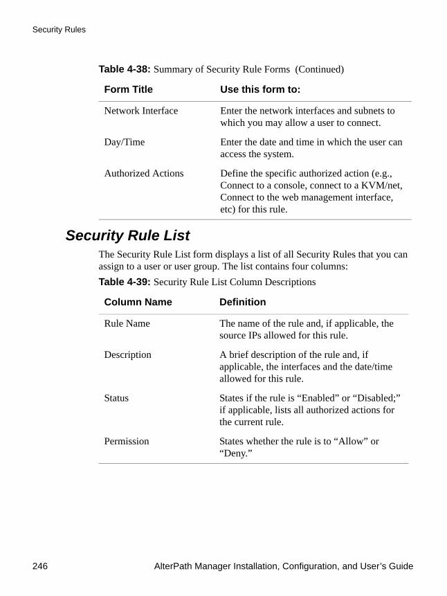
Security Rules
246 AlterPath Manager Installation, Configuration, and User’s Guide
Security Rule ListThe Security Rule List form displays a list of all Security Rules that you can assign to a user or user group. The list contains four columns:
Network Interface Enter the network interfaces and subnets to which you may allow a user to connect.
Day/Time Enter the date and time in which the user can access the system.
Authorized Actions Define the specific authorized action (e.g., Connect to a console, connect to a KVM/net, Connect to the web management interface, etc) for this rule.
Table 4-39: Security Rule List Column Descriptions
Column Name Definition
Rule Name The name of the rule and, if applicable, the source IPs allowed for this rule.
Description A brief description of the rule and, if applicable, the interfaces and the date/time allowed for this rule.
Status States if the rule is “Enabled” or “Disabled;” if applicable, lists all authorized actions for the current rule.
Permission States whether the rule is to “Allow” or “Deny.”
Table 4-38: Summary of Security Rule Forms (Continued)
Form Title Use this form to:

Configuration and Administration 247
Security Rules
Figure 4-76: Security Rules List Form
To Add or Edit a Security RuleTo add or edit a security rule, perform the following steps:
1. From the menu select Security Rule.
The system displays the Security Rule list form (see previous page).
2. Select the “Add” button to add, or select an existing rule to edit.
The system displays the “Security Rules General” form.

Security Rules
248 AlterPath Manager Installation, Configuration, and User’s Guide
Figure 4-77: Security Rules General Form
3. From the Security Rule General form, enter the rule name (required), a brief description of the rule, its status (Enabled or Disabled), and the rule to be applied to the entire rule (Allow or Deny).
4. Click on the “Save” button.
To Configure Conditions for Accepting Source Pages 1. Click on the “Source IP” tab to configure the conditions for accepting
source pages for the current rule.
The system displays the Security Rule Source IP form.

Configuration and Administration 249
Security Rules
Figure 4-78: Security Rule Source Filtering Form
2. Complete or modify the form, as needed. Table 4-40: Security Rules, Source IP
Element Function
Source Filtering (tab) Title of the current tabbed form.
Permission The default rule (Allow or Deny) that applies to the entire security rule. The default permission is configured from the “General” tabbed form.
Add Source Conditions This section allows you to define the Source IP that will be used as the conditions for applying it to the rule.
IP The IP address to be added to the Added Source IP Conditions list box.
Netmask The netmask to be added to the Added Source IP Conditions list.

Security Rules
250 AlterPath Manager Installation, Configuration, and User’s Guide
3. Click on the “Save” button.
Warning! If the domain name server is down or is not configured correctly, users with security rules that have host/domainname filtering with deny permission will still be denied access to the APM because the security rule can not be verified. If the rule is “Allow” the rule is ignored and the next
Added Source IP Conditions
List of source IP addresses to be applied to the rule.
Start IP The starting IP address of a range of IP addresses.
End IP The ending IP address of a range of IP addresses.
Hostname Hostname of the workstation. If the domainname is not entered, then the domainname of the APM is used to filter the source.
Domain Domain name on which the workstation will connect from. If the workstation belongs to subdomain and only domain filtering is entered, all sub domains are allowed or denied access based on the rule permission.
Add Button to add to the conditions list the address, address range, or hostname/domainname you just entered in the IP or Netmask field.
Delete Button to delete a selected IP address, address range, or hostname/domainname from the adjacent Source IP Conditions list box.
Back Button to return to the previous page.
Save Button to save your configuration.
Table 4-40: Security Rules, Source IP (Continued)
Element Function

Configuration and Administration 251
Security Rules
“allow” rule is considered.
All successful DNS reverse lookup entries are cached for about 30 minutes, and all unsuccessful DNS reverse lookup entries are cached for about 15 minutes. If a user has a security rule with “deny,” and the DNS lookup of source was not verified, the user will be denied access to the APM for 15 minutes. In this case, the user must wait for 15 minutes before attempting to sign on again to the APM.
Security Rules: Network IntfThe Network Intf (Local Area Network Interfaces) form allows you to define the interfaces to which a user is either allowed to connect, or denied access. This feature is designed for situations where multiple network or LAN segments are used or defined.
Figure 4-79: Security Rule Network Interface Form

Security Rules
252 AlterPath Manager Installation, Configuration, and User’s Guide
Security Rule: Date/Time ConfigurationThe Date/Time tabbed form allows you to specify the time in which the rule will allow or deny access to the system.
Table 4-41: Security Rules, Network Intf
Element Function
Network Interface (tab) Tab to select the current form.
Permission The default rule (Allow or Deny) that applies to the current form and the entire security rule. The permission is configured from the “General” tabbed form.
Select Net Intf Conditions
List box that lists all LAN interfaces. Select the LAN interface(s) that will be applied to the rule.
Add Button to select items from the “Select Net Intf Conditions” list box and add to the “Selected LAN ITF Conditions” list box.
Delete Button to remove any “Selected Net Intf Conditions” from the right list box.
Selected Net Intf Conditions
List of selected Net Intf conditions that will be applied by the rule to the policy.
Back Button to return to the previous page.
Save Button to save your configuration.

Configuration and Administration 253
Security Rules
Figure 4-80: Security Rule Day / Time Form
Table 4-42: Security Rules Date/Time Form
Element Function
Day/Time (tab) Tab title to select the current form.
Permission The rule (Allow or Deny) that applies to the entire security rule. The default permission is configured from the “General” tabbed form.
[Day/Time Table] The table represents the days of a week (rows) and the hours of a day (columns).
Add Time Period Conditions
Define below this title the time period conditions that applies to the default rule by clicking the appropriate boxes.
Sun - Sat (check boxes) Select the day(s) to be applied to the default rule.
Start Time Specify a Start Time to be applied to the selected day(s), as part of the time conditions.
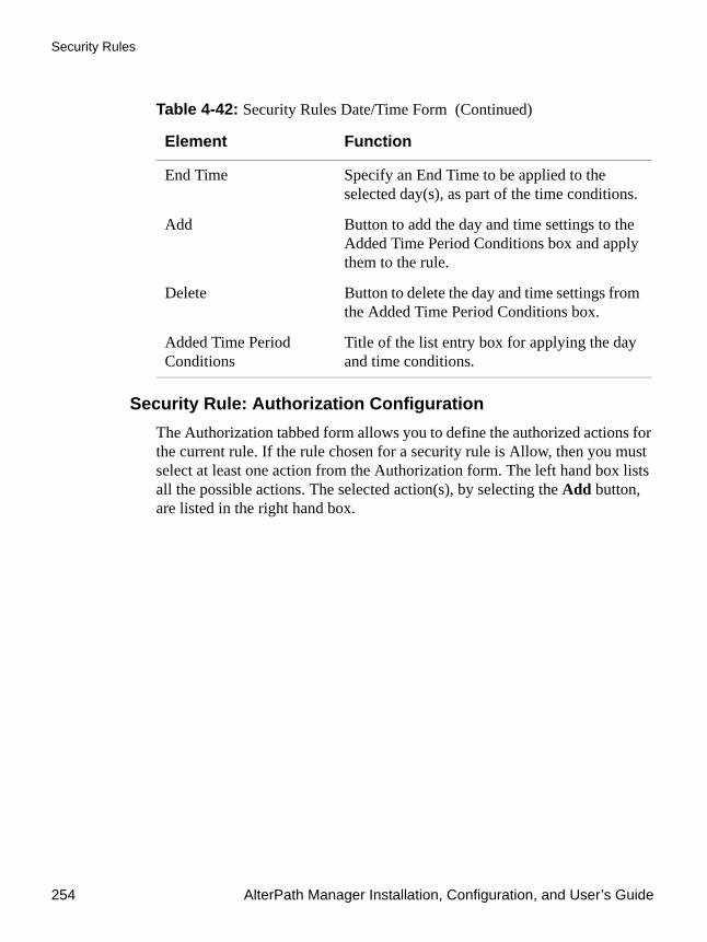
Security Rules
254 AlterPath Manager Installation, Configuration, and User’s Guide
Security Rule: Authorization ConfigurationThe Authorization tabbed form allows you to define the authorized actions for the current rule. If the rule chosen for a security rule is Allow, then you must select at least one action from the Authorization form. The left hand box lists all the possible actions. The selected action(s), by selecting the Add button, are listed in the right hand box.
End Time Specify an End Time to be applied to the selected day(s), as part of the time conditions.
Add Button to add the day and time settings to the Added Time Period Conditions box and apply them to the rule.
Delete Button to delete the day and time settings from the Added Time Period Conditions box.
Added Time Period Conditions
Title of the list entry box for applying the day and time conditions.
Table 4-42: Security Rules Date/Time Form (Continued)
Element Function
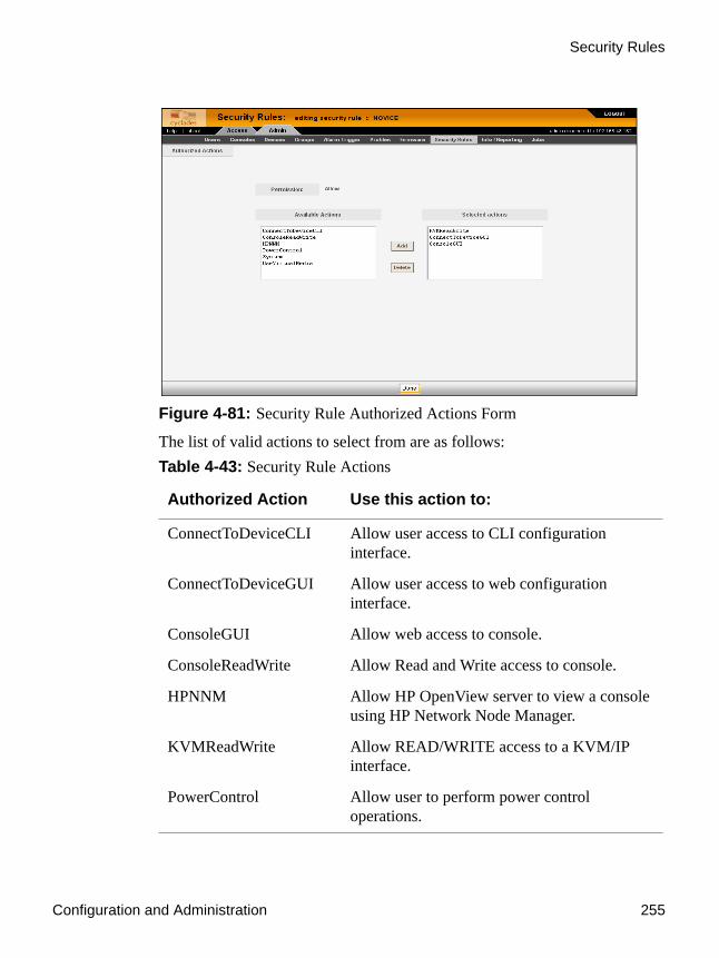
Configuration and Administration 255
Security Rules
Figure 4-81: Security Rule Authorized Actions Form
The list of valid actions to select from are as follows:Table 4-43: Security Rule Actions
Authorized Action Use this action to:
ConnectToDeviceCLI Allow user access to CLI configuration interface.
ConnectToDeviceGUI Allow user access to web configuration interface.
ConsoleGUI Allow web access to console.
ConsoleReadWrite Allow Read and Write access to console.
HPNNM Allow HP OpenView server to view a console using HP Network Node Manager.
KVMReadWrite Allow READ/WRITE access to a KVM/IP interface.
PowerControl Allow user to perform power control operations.
Power Management Support
256 AlterPath Manager Installation, Configuration, and User’s Guide
To Delete a Security RuleTo delete a security rule, perform the following steps:
1. From the main menu, select “Security Rules.”
2. From the Security Rules List form, check mark the Security Rule that you wish to delete.
3. Click on the “Delete” button.
Power Management SupportTo configure Power management support, you must first configure a power management (PM) device that is connected to a KVM/net, OnSite, or ACS/TS device managed by the APM. Then you configure outlets on the PM and associate the outlets with consoles. Figure 4-82 shows an example of an administrative PM details edit form.
System Allow system access.
UserVirtualMedia Allow user access to blades.
Table 4-43: Security Rule Actions (Continued)
Authorized Action Use this action to:

Configuration and Administration 257
Power Management Support
Figure 4-82:IPDU Details FormTable 4-44: IPDU Device Details
Element Definition
Details Opening tab that is the default when you either create or edit a power management device.
Users ACL Tab that opens the PM device Users Access Control List form
Groups Tab that opens the PM device groups access form
IPDUs Info Tab that opens a display of data read back from the PM device after you click on the “Get Information” button. This tab does not appear when you are creating a PM device.
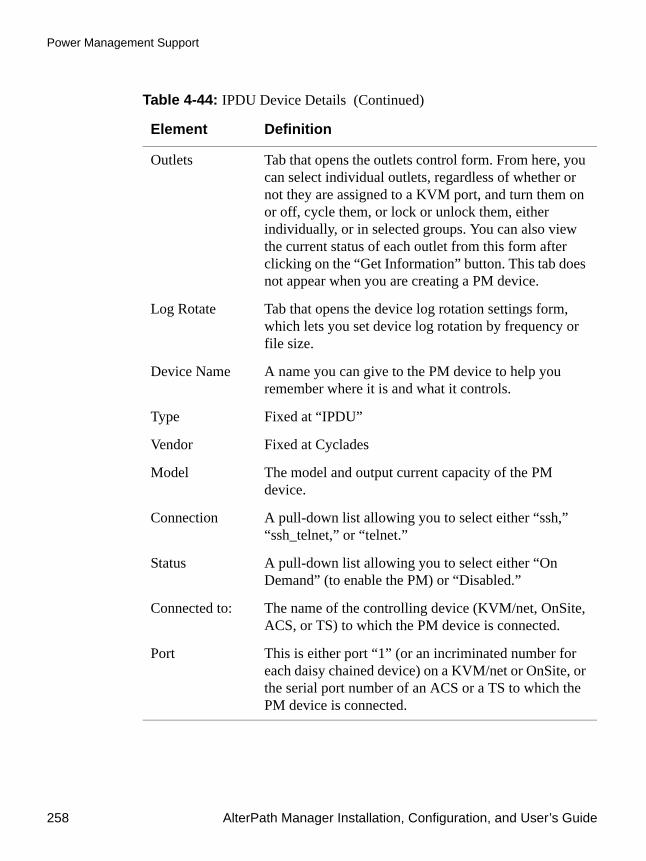
Power Management Support
258 AlterPath Manager Installation, Configuration, and User’s Guide
Outlets Tab that opens the outlets control form. From here, you can select individual outlets, regardless of whether or not they are assigned to a KVM port, and turn them on or off, cycle them, or lock or unlock them, either individually, or in selected groups. You can also view the current status of each outlet from this form after clicking on the “Get Information” button. This tab does not appear when you are creating a PM device.
Log Rotate Tab that opens the device log rotation settings form, which lets you set device log rotation by frequency or file size.
Device Name A name you can give to the PM device to help you remember where it is and what it controls.
Type Fixed at “IPDU”
Vendor Fixed at Cyclades
Model The model and output current capacity of the PM device.
Connection A pull-down list allowing you to select either “ssh,” “ssh_telnet,” or “telnet.”
Status A pull-down list allowing you to select either “On Demand” (to enable the PM) or “Disabled.”
Connected to: The name of the controlling device (KVM/net, OnSite, ACS, or TS) to which the PM device is connected.
Port This is either port “1” (or an incriminated number for each daisy chained device) on a KVM/net or OnSite, or the serial port number of an ACS or a TS to which the PM device is connected.
Table 4-44: IPDU Device Details (Continued)
Element Definition

Configuration and Administration 259
Power Management Support
Alarm threshold If set to 0, the alarm will occur when default current threshold of the PM is exceeded. You can set this to an alternate threshold below the default threshold, if you wish.
Over current protection
If selected, automatically shuts off an outlet if the current at that outlet exceeds the current limit.
Buzzer If selected, sounds a buzzer if the alarm threshold is exceeded.
Syslog If selected, allows PM device alarm events to be logged.
Status Drop-down list lets you choose “OnDemand” or “Disable.”
Back Button that allows you to go back to the previous form without saving any configuration parameters.
Reset Button that allows you to revert back to the previously saved parameters.
Save Button that saves the current PM parameter settings.
Save & Create Outlets
Button that saves the current PM parameter settings and configures all the outlets on the device.
Save & Autodiscover
Button that saves the current PM parameter settings and interrogates the device controlling the PM (if it can be detected) for existing outlet configurations.
Get Information This button is used to update information displayed in the “IPDUs Info” and the “Outlets” forms, since they are not updated in real time.
Table 4-44: IPDU Device Details (Continued)
Element Definition

Power Management Support
260 AlterPath Manager Installation, Configuration, and User’s Guide
To Configure a PM Device1. If you have not already done so, configure the device on which the
AlterPath PM is connected.
For a KVM/net or an OnSite, the PM should be physically connected to the “AUX” port. For an ACS or a TS, the PM should be physically connected to one of the serial console ports. Use a straight through serial (not console) cable.
2. If you have not already configured the consoles for this device, configure them now.
For a KVM/net or an OnSite, be sure to include the KVM ports for which you want to assign AlterPath PM outlets.
For an ACS or a TS, be sure to configure the serial port to which the PM is attached, as a PM port. You do this from the ACS or TS WMI, either directly or via an APM proxy connection (see “Proxies” on page 121).
3. From the “Admin” tab, select: “Devices” > “Add” button.
4. Select “IPDU” from the “Device Types” pull-down list and click the “Select” button.
The “IPDU” create/device details form appears (see Figure 4-82, “IPDU Details Form”).
5. Give the IPDU device a name.
6. Select a PM model number from the “Model” pull-down list.
The model number must match the model of the PM connected to the managed AlterPath device.
7. Select the connection type from the “Connection” pull-down list.
The choices are ssh, ssh_telnet, and telnet.
8. Be sure “On Demand” is selected in the “Status” pull-down list (unless you want this feature disabled).
9. Be sure the “Connected to” pull-down list shows the device associated with the PM you are configuring.
10. Save the PM configuration, by clicking one of the following buttons:
a. Create
Configuration and Administration 261
Redundant (Fault Tolerant) Configuration
b. Create Device & Outlets
c. Create Device & Autodiscover
11. If you have not uploaded the PM device during the previous step, select: “Admin” tab > “Devices” menu.
The devices list appears. The PM device and possibly, the device to which it is attached will have indications in the “Upload” columns indicating that an upload is required.
12. Click on the checkbox next to the listed devices requiring uploads.
13. Click the “Upload” button near the bottom of the form, and wait for the upload to take place.
Note: If you create an admin user with access restricted to a PM device only, and such a user subsequently logs onto the APM and uploads the PM device, the parent device will also be uploaded. This happens even if the parent device is specifically not checked in the upload menu.
Redundant (Fault Tolerant) ConfigurationNote: This feature is not supported on the APM E2000.
Heartbeat, Redundancy, Data Synchronization, and Failover support provides the ability to back up and restore an APM 2500 or APM 5000 system with little or no downtime in the event of a failure of a primary APM. By using the heartbeat protocol in conjunction with network RAID, a redundant APM automatically takes over device and console management in the event of a failure of the primary APM or its Ethernet connection.
A heartbeat signal between a primary and secondary APM verifies that the primary APM is up and running. If the heartbeat signal is not received from the primary APM for a predetermined interval (5 seconds by default), the primary APM is assumed to be down and the redundant APM takes over. When the primary APM is brought back up, the secondary APM fails back and synchronizes data with the primary APM.
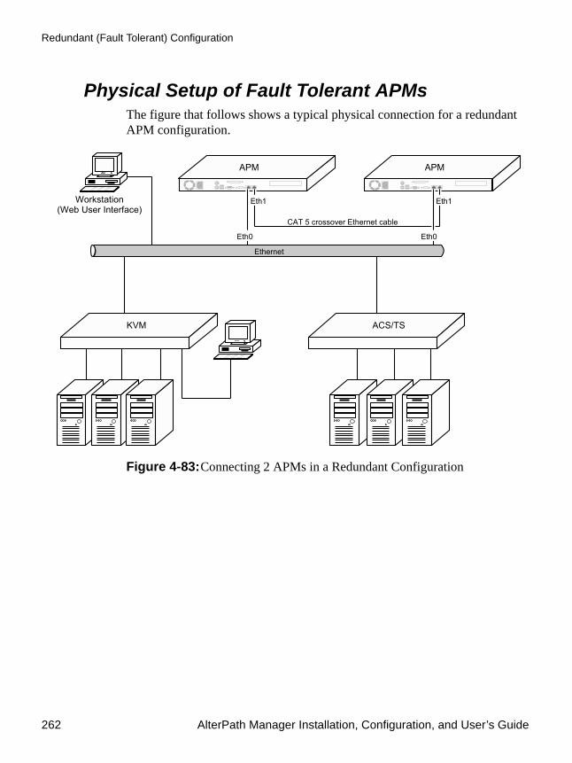
Redundant (Fault Tolerant) Configuration
262 AlterPath Manager Installation, Configuration, and User’s Guide
Physical Setup of Fault Tolerant APMsThe figure that follows shows a typical physical connection for a redundant APM configuration.
Figure 4-83:Connecting 2 APMs in a Redundant Configuration

Configuration and Administration 263
Redundant (Fault Tolerant) Configuration
WMI Configuration of Fault Tolerant APMs The following figure shows the APM Heartbeat Configuration form.
Figure 4-84:APM Heartbeat Configuration Form.
The next two figures show a detailed view of a filled in Heartbeat Configuration form for the primary APM in the configuration, and a detailed view of a filled in Heartbeat Configuration form for the redundant APM. The two forms are filled out almost identically, but observe the following fields in the two forms to see how they differ:
• Configured State
• Node Name Current System Mated System
• IP Address Current System Mated System

Redundant (Fault Tolerant) Configuration
264 AlterPath Manager Installation, Configuration, and User’s Guide
Figure 4-85:Detailed View - APM Heartbeat Form for Primary
Figure 4-86:Detailed View - APM Heartbeat Form for Redundant
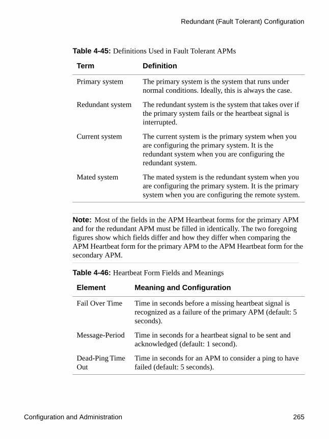
Configuration and Administration 265
Redundant (Fault Tolerant) Configuration
Note: Most of the fields in the APM Heartbeat forms for the primary APM and for the redundant APM must be filled in identically. The two foregoing figures show which fields differ and how they differ when comparing the APM Heartbeat form for the primary APM to the APM Heartbeat form for the secondary APM.
Table 4-45: Definitions Used in Fault Tolerant APMs
Term Definition
Primary system The primary system is the system that runs under normal conditions. Ideally, this is always the case.
Redundant system The redundant system is the system that takes over if the primary system fails or the heartbeat signal is interrupted.
Current system The current system is the primary system when you are configuring the primary system. It is the redundant system when you are configuring the redundant system.
Mated system The mated system is the redundant system when you are configuring the primary system. It is the primary system when you are configuring the remote system.
Table 4-46: Heartbeat Form Fields and Meanings
Element Meaning and Configuration
Fail Over Time Time in seconds before a missing heartbeat signal is recognized as a failure of the primary APM (default: 5 seconds).
Message-Period Time in seconds for a heartbeat signal to be sent and acknowledged (default: 1 second).
Dead-Ping Time Out
Time in seconds for an APM to consider a ping to have failed (default: 5 seconds).
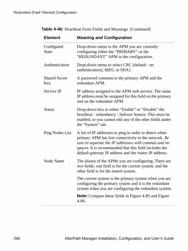
Redundant (Fault Tolerant) Configuration
266 AlterPath Manager Installation, Configuration, and User’s Guide
Configured State
Drop-down menu to the APM you are currently configuring either the “PRIMARY” or the “REDUNDANT” APM in the configuration.
Authentication Drop-down menu to select CRC (default - no authentication), MD5, or SHA1.
Shared Secret Key
A password common to the primary APM and the redundant APM.
Service IP IP address assigned to the APM web service. The same IP address must be assigned for this field on the primary and on the redundant APM.
Status Drop-down box to either “Enable” or “Disable” the heartbeat - redundancy - failover feature. This must be enabled, or you cannot edit any of the other fields under the “System” tab.
Ping Nodes List A list of IP addresses to ping in order to detect when primary APM has lost connectivity to the network. Be sure to separate the IP addresses with commas and no spaces. It is recommended that this field includes the default gateway IP address and the router IP address.
Node Name The aliases of the APMs you are configuring. There are two fields: one field is for the current system, and the other field is for the mated system.
The current system is the primary system when you are configuring the primary system and it is the redundant system when you are configuring the redundant system.
Note: Compare these fields in Figure 4-85 and Figure 4-86.
Table 4-46: Heartbeat Form Fields and Meanings (Continued)
Element Meaning and Configuration

Configuration and Administration 267
Redundant (Fault Tolerant) Configuration
IP Address The IP addresses of the APMs you are configuring. There are two fields: one field is for the current system, and the other field is for the mated system
The current system is the primary system when you are configuring the primary system and it is the redundant system when you are configuring the redundant system.
Note: Compare these fields in Figure 4-85 and Figure 4-86.
Reset Button that resets the data in the fields of the form.
Save Button to save the configuration
Reboot Button that reboots the system you are viewing.
Force Fail Over/Force Fail Back
If you are viewing the Heartbeat form for the primary APM, this button is labeled “Force Failover”. If you are viewing the Heartbeat form for the redundant APM, this button is labeled “Force Failback”.
This button only appears when the heartbeat is active.
Table 4-46: Heartbeat Form Fields and Meanings (Continued)
Element Meaning and Configuration

Redundant (Fault Tolerant) Configuration
268 AlterPath Manager Installation, Configuration, and User’s Guide
Figure 4-87:APM Synchronization Form
To Set Up a Fault Tolerant APM Configuration
Note: This feature is not supported on the APM E2000.
1. Be sure both APM systems are upgraded with the same APM 1.4.0 GA release (refer to “To Upgrade the APM Firmware” on page 320).
Table 4-47: Synchronization Form Fields and Meanings
Element Meaning and Configuration
Synchronization Speed
The default is 700000 KB/second. This is the maximum speed allowed for this field.
Note: The APM 2500 and the APM 5000 synchronize using network RAID and DRBD (Distributed Replicated Block Device). This enables replication of data from the primary system to the redundant system in real time.
Port Number Leave this at 7791.

Configuration and Administration 269
Redundant (Fault Tolerant) Configuration
Caution: You can mix APM hardware platforms, but you must be sure the APM 5000 has APM 5000 firmware and the APM 2500 has APM 2500 firmware. Both APMs must have firmware of the same build number and date.
2. From the primary APM’s console, run the backup command on the primary APM system and back up the database (refer to “Backup and Restore Scenarios” on page 322):
a. Perform a backup confexample: # backup conf [email protected]:backup.conf
b. Perform a backup logexample: # backup log [email protected]:backup.log
3. From the redundant APM’s console, run the restore command on the remote APM system and restore the database:
a. Perform a restore confexample: # restore conf [email protected]:backup.conf
b. Perform a restore logexample: # restore log [email protected]:backup.log
Your primary APM and redundant APM now have matching firmware and databases.
4. Physically configure two APMs with Eth0 ports on a common LAN. The IP addresses of the APMs must be static Figure 4-83 shows the physical configuration of the APMs.
5. Connect the Eth1 ports on both APMs with a Cat-5 Ethernet crossover cable. This is the heartbeat and network RAID signal cable.
Configuration of the Primary APM6. Log onto the WMI of the Primary APM as “admin” and select: “System”
tab > “Cluster Settings” > “Heartbeat” tab.

Redundant (Fault Tolerant) Configuration
270 AlterPath Manager Installation, Configuration, and User’s Guide
7. Select the “Status” drop-down box and select “Enable.”
The rest of the fields in the form will become active. The default settings for “Fail Over Time,” “Message-Period,” and “Dead Ping Timeout” can remain as they are.
8. Select the “Configured State” drop-down box and set it to “Primary.”
9. Select the “Authentication” drop-down box and choose “CRC,” MD5,” or “SHA1.”
10. Enter a password in the “Shared Secrets Key” field.
This password must be the same when you enter it in the “Shared Secrets Key” field for the redundant APM.
11. Enter an IP address in the “Service IP” field.
This is an IP address for the APM web service. It must be a static address and it must be the same IP address used when configuring the Service IP for the redundant APM.
12. Fill in the “Ping Nodes List” field with IP addresses to ping in order to detect when primary APM has lost connectivity to the network. It is recommended that this field includes the default gateway IP address and the router IP address. Be sure to separate the IP addresses with commas and no spaces.
13. Enter an alias in the “Node Name” field for the primary APM in the column for the current system.
14. Enter the IP address for the primary APM in the “IP Address” field in the column for the current system.
15. Enter an alias in the “Node Name” field for the redundant APM in the column for the mated system.
16. Enter the IP address for the redundant APM in the “IP Address” field in the column for the mated system.
17. You should be able to leave the default settings as they are in the form under the “Synchronization” tab.
18. Select the “Admin” tab > “Alarm Trigger”
19. Click on “Resources Take Over” and select “Enable” from the drop-down field.

Configuration and Administration 271
Redundant (Fault Tolerant) Configuration
20. Click on “Take Over” and select “Enable” from the drop-down field.
Configuration of the Redundant APM21. Log onto the WMI of the redundant APM as “admin” and select:
“System” tab > “Cluster Settings” > “Heartbeat” tab.
22. Select the “Status” drop-down box and select “Enable.”
The rest of the fields in the form will become active. The default settings for “Fail Over Time,” “Message-Period,” and “Dead Ping Timeout” can remain as they are.
23. Select the “Configured State” drop-down box and set it to “Redundant.”
24. Select the “Authentication” drop-down box and choose “CRC,” MD5,” or “SHA1.”
25. Enter a password in the “Shared Secrets Key” field.
This password must be the same as when you entered it in the “Shared Secrets Key” field for the primary APM (step 10).
26. Enter an IP address in the “Service IP” field.
This is an IP address for the APM web service. It must be a static address and it must be the same IP address used when you configured the Service IP for the primary APM (11).
27. Fill in the “Ping Nodes List” field with IP addresses to ping in order to detect when primary APM has lost connectivity to the network. It is recommended that this field includes the default gateway IP address and the router IP address. Be sure to separate the IP addresses with commas and no spaces.
28. Enter an alias in the “Node Name” field for the redundant APM in the column for the current system.
29. Enter the IP address for the redundant APM in the “IP Address” field in the column for the current system.
30. Enter an alias in the “Node Name” field for the primary APM in the column for the mated system.
31. Enter the IP address for the primary APM in the “IP Address” field in the column for the mated system.
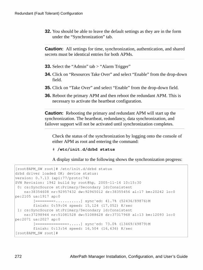
Redundant (Fault Tolerant) Configuration
272 AlterPath Manager Installation, Configuration, and User’s Guide
32. You should be able to leave the default settings as they are in the form under the “Synchronization” tab.
Caution: All settings for time, synchronization, authentication, and shared secrets must be identical entries for both APMs.
33. Select the “Admin” tab > “Alarm Trigger”
34. Click on “Resources Take Over” and select “Enable” from the drop-down field.
35. Click on “Take Over” and select “Enable” from the drop-down field.
36. Reboot the primary APM and then reboot the redundant APM. This is necessary to activate the heartbeat configuration.
Caution: Rebooting the primary and redundant APM will start up the synchronization. The heartbeat, redundancy, data synchronization, and failover support will not be activated until synchronization completes.
Check the status of the synchronization by logging onto the console of either APM as root and entering the command:
# /etc/init.d/drbd status
A display similar to the following shows the synchronization progress:
[root@APM_SW root]# /etc/init.d/drbd statusdrbd driver loaded OK; device status:version: 0.7.13 (api:77/proto:74)SVN Revision: 1942 build by root@hp, 2005-11-16 10:15:30 0: cs:SyncSource st:Primary/Secondary ld:Consistent ns:38354608 nr:92957432 dw:92965012 dr:38355456 al:17 bm:20242 lo:0 pe:2105 ua:1917 ap:0 [========>...........] sync'ed: 41.7% (52436/89876)M finish: 0:59:04 speed: 15,124 (17,052) K/sec 1: cs:SyncSource st:Primary/Secondary ld:Consistent ns:37298944 nr:51081528 dw:51088628 dr:37317968 al:13 bm:12093 lo:0 pe:2071 ua:2027 ap:0 [==============>.....] sync'ed: 73.0% (13469/49879)M finish: 0:13:54 speed: 16,504 (16,636) K/sec[root@APM_SW root]#

Configuration and Administration 273
Redundant (Fault Tolerant) Configuration
When the synchronization of the two APMs is complete, the display be similar to the following:
Fault tolerance is now enabled.
Note: This information can also be viewed from the WMI of either APM. Log onto the WMI as admin, and go to “System” > “Status” > “Sync Status” tab. A screen similar to the following appears:
Figure 4-88:Synchronization Status Viewed from the WMI
[root@APM_SW root]# /etc/init.d/drbd statusdrbd driver loaded OK; device status:version: 0.7.13 (api:77/proto:74)SVN Revision: 1942 build by root@hp, 2005-11-16 10:15:30 0: cs:Connected st:Primary/Secondary ld:Consistent ns:92041488 nr:92957432 dw:92965160 dr:92034520 al:17 bm:23520 lo:0 pe:0 ua:0 ap:0 1: cs:Connected st:Primary/Secondary ld:Consistent ns:51083528 nr:51081528 dw:51088952 dr:51094120 al:13 bm:12936 lo:0 pe:0 ua:0 ap:0[root@APM_SW root]#

Redundant (Fault Tolerant) Configuration
274 AlterPath Manager Installation, Configuration, and User’s Guide
To Upgrade Firmware on Redundant APMs1. Log onto the WMI of the primary APM as admin and select:
“System” tab > “Cluster Settings” > “Heartbeat” tab > “Status” drop-down box > “Disable”
2. Log onto the WMI of the redundant APM as admin and select: “System” tab > “Cluster Settings” > “Heartbeat” tab > “Status” drop-down box > “Disable”
3. Reboot both APMs.
The heartbeat and network RAID signals will now be stopped. When the APMs reboot, they will be running as individual APMs
4. After the APMs reboot, upgrade the firmware on each APM. See “To Upgrade the APM Firmware” on page 320.“To Upgrade the APM Firmware” in Chapter 5 of the
Caution: You can mix APM hardware platforms, but you must be sure the APM 5000 has APM 5000 firmware and the APM 2500 has APM 2500 firmware. Both APMs must have firmware of the same build number and date.
5. Reboot the primary APM and then reboot the secondary APM.
6. Log onto the WMI of the primary APM as admin and select: “System” tab > “Cluster Settings” > “Heartbeat” tab > “Status” drop-down box > “Enable”
7. Log onto the WMI of the redundant APM as admin and select: “System” tab > “Cluster Settings” > “Heartbeat” tab > “Status” drop-down box > “Enable”
8. Reboot the primary APM and then reboot the secondary APM. This is necessary to activate the heartbeat configuration.
Caution: Rebooting the primary and redundant APM will start up the synchronization. The heartbeat, redundancy, data synchronization, and failover support will not be activated until synchronization completes.
9. Check the status of the synchronization by either:

Configuration and Administration 275
Redundant (Fault Tolerant) Configuration
a. logging onto the console of either APM and entering the command: # /etc/init.d/drbd status
b. or by logging onto the WMI of either APM as admin and going to “System” > “Status” > “Sync Status” tab.
After the synchronization completes, the heartbeat and network RAID signals will start up and the fault tolerant configuration will be active.

Redundant (Fault Tolerant) Configuration
276 AlterPath Manager Installation, Configuration, and User’s Guide

This chapter presents some procedures for configuring the AlterPath Manager E2000, 2500, and 5000 through the Command Line Interface (CLI).
First Time Configuration aside, Cyclades recommends the use of the CLI only for advanced admin users who are proficient with CLI, and would like more control over the configuration features of the AlterPath Manager.
This chapter is organized as follows:
Working from a CLI Page 278
CLI Commands Page 280
Copying and Pasting Text within the Console Applet Window
Page 281
Connecting Directly to Ports Page 281
Sample Command Line Interface Page 283
Console Session Hot Keys Page 285
Set Commands Page 286
Re-defining the Interrupt Key Page 296
To Change the Number of Consoles per Page
Page 297
Sudo Support Page 299
Ethernet Bonding Page 300
Ethernet Port Configuration Page 303
HP OpenView NNM Integration Page 303
Modem Card Configuration Page 303
Serial Card Configuration Page 305
Chapter 5Advanced Configuration

Working from a CLI
278 AlterPath Manager Installation, Configuration, and User’s Guide
Working from a CLIThe AlterPath Manager allows you to use a command line interface (CLI) as an alternative to the web interface. You can use a terminal or terminal emulator on a local workstation to connect to the APM’s console port. You may also use a Linux or Windows-based secure shell (SSH) client. The same restrictions to the web management interface apply to the CLI.
Note: Throughout this manual, the term “CLI” refers to the command line interface provided by the APM’s console port. This interface can also be accessed through an ssh connection to the APM’s IP address. There is also a CLI shell that provides access to ACS/TS type consoles.
To Log Into the Serial Console Port1. Connect a terminal or a computer with a terminal emulator to the APM’s
serial console port, using a null modem cable.
Configuring Dial Out and Dial Back
Page 307
Modem Dial Back for ACS Page 308
Changing the Ports to be Proxied Page 311
Creating the krb5.keytab for Kerberos Authentication
Page 314
Firmware Page 319
Backing Up User Data Page 321
Managing Log Files Page 322
System Recovery Guidelines Page 322
Changing the Database Configuration
Page 326
Restoring Your Configuration Page 326

Advanced Configuration 279
Working from a CLI
2. Power on the APM and start the terminal or terminal emulator.
3. When prompted, log in.
To Do a Windows SSH Login1. Using an IP connection client such as PuTTY, select “SSH” for the
protocol setting.
2. In the client’s IP address window, type the IP address of the APM.
A CLI screen will be launched.
3. When prompted, log onto the APM.
To Do a Linux or UNIX SSH LoginTo connect to the AlterPath Manager, from a Linux or UNIX shell prompt, enter the following shell commands:
# ssh -l <username> <IP_address_of_APM># <password>
Note: The “l” in ssh-1 is the alphabetical character “l” as in lemon.
If you are an admin user, the system will display a menu.
You can either run the “CLI” shell from the menu, or you can go directly to a Linux system prompt.
If you log in to the CLI as root, you will only have access to the Linux system prompt, but you will have all the normal privileges as any root user on any Linux system.
If you are a regular user, you will get the “CLI” shell alone, without a menu or system prompt. This will give you access primarily to serial (ACS/TS) consoles configured on the APM.
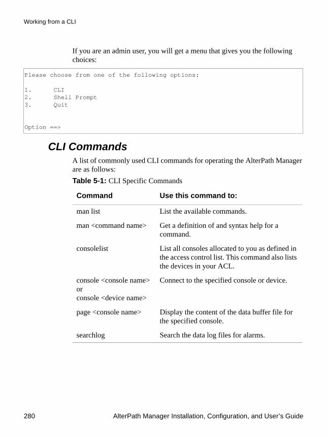
Working from a CLI
280 AlterPath Manager Installation, Configuration, and User’s Guide
If you are an admin user, you will get a menu that gives you the following choices:
CLI CommandsA list of commonly used CLI commands for operating the AlterPath Manager are as follows:
Please choose from one of the following options: 1. CLI2. Shell Prompt3. Quit Option ==>
Table 5-1: CLI Specific Commands
Command Use this command to:
man list List the available commands.
man <command name> Get a definition of and syntax help for a command.
consolelist List all consoles allocated to you as defined in the access control list. This command also lists the devices in your ACL.
console <console name>or console <device name>
Connect to the specified console or device.
page <console name> Display the content of the data buffer file for the specified console.
searchlog Search the data log files for alarms.

Advanced Configuration 281
Working from a CLI
Copying and Pasting Text within the Console Applet Window
The APM allows you to copy and paste text within your console (Java applet) window to facilitate any command line configuration of a device and other similar operations.
To use the copy & paste feature, right click your mouse.
This invokes a pop-up menu with the following options:
The copy and paste feature follows the standard Windows/GUI convention of clicking the mouse, dragging it over the text to be copied, releasing the mouse to capture the entire text, and then positioning your cursor to the desired destination as you select the Paste option.
Note: Linux browsers do not support the Copy and Paste feature.
Connecting Directly to PortsIt is possible to connect to console ports using the AlterPath Manager as a security proxy.
To Connect from a Windows SSH Client 1. Using a Windows SSH client, such as Putty, select “SSH” for the
protocol.
Table 5-2: Console Applet Window Menu Options
Menu Option Use this option to . . .
Copy Copy text from the applet window or another source.
Paste Paste text to the applet window.
Disconnect Close the applet window and disconnect your SSH session.
Send Break Cause an OK prompt to appear on the applet screen.
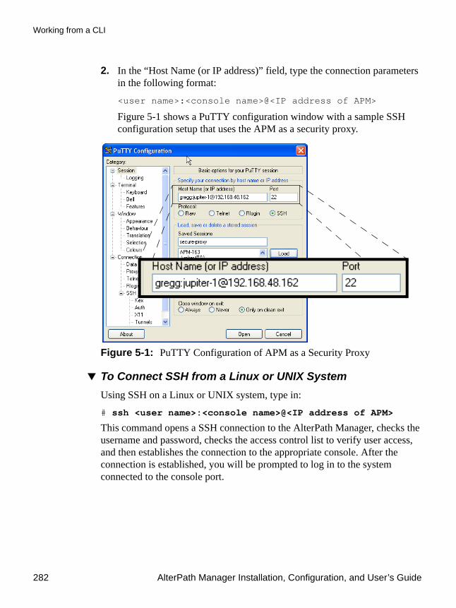
Working from a CLI
282 AlterPath Manager Installation, Configuration, and User’s Guide
2. In the “Host Name (or IP address)” field, type the connection parameters in the following format:
<user name>:<console name>@<IP address of APM>
Figure 5-1 shows a PuTTY configuration window with a sample SSH configuration setup that uses the APM as a security proxy.
Figure 5-1: PuTTY Configuration of APM as a Security Proxy
To Connect SSH from a Linux or UNIX SystemUsing SSH on a Linux or UNIX system, type in:
# ssh <user name>:<console name>@<IP address of APM>
This command opens a SSH connection to the AlterPath Manager, checks the username and password, checks the access control list to verify user access, and then establishes the connection to the appropriate console. After the connection is established, you will be prompted to log in to the system connected to the console port.

Advanced Configuration 283
Working from a CLI
Sample Command Line InterfaceAn example of a command line interface as accessed by an admin follows:
Cyclades-APM V_1.4.0-RC1 (Oct/11/2005) - Console (kernel 2.4.25) APM_Gregg login: adminPassword: *************************************************************************** WARNING: changing system files directly is dangerous and may adversely ** affect your system's functionality. Proceed with caution, and ** only if you know what you are doing! ***************************************************************************

Working from a CLI
284 AlterPath Manager Installation, Configuration, and User’s Guide
The foregoing banner message displays briefly and then it is replaced by the following banner and prompt:
---------------------------------------------------- AlterPath Manager ---------------------------------------------------- Please choose from one of the following options: 1. CLI2. Shell Prompt3. Quit Option ==>
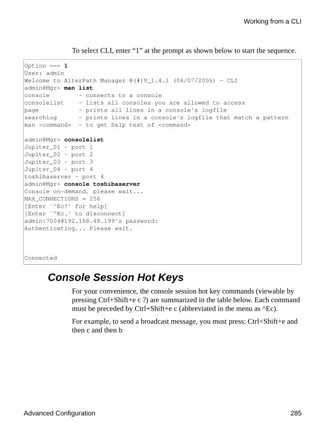
Advanced Configuration 285
Working from a CLI
To select CLI, enter “1” at the prompt as shown below to start the sequence.
Console Session Hot KeysFor your convenience, the console session hot key commands (viewable by pressing Ctrl+Shift+e c ?) are summarized in the table below. Each command must be preceded by Ctrl+Shift+e c (abbreviated in the menu as ^Ec).
For example, to send a broadcast message, you must press: Ctrl+Shift+e and then c and then b
Option ==> 1User: adminWelcome to AlterPath Manager @(#)V_1.4.1 (04/07/2006) - CLIadmin@Mgr> man listconsole - connects to a consoleconsolelist - lists all consoles you are allowed to accesspage - prints all lines in a console's logfilesearchlog - prints lines in a console's logfile that match a patternman <command> - to get help text of <command> admin@Mgr> consolelistJupiter_01 - port 1Jupiter_02 - port 2Jupiter_03 - port 3Jupiter_04 - port 4toshibaserver - port 4admin@Mgr> console toshibaserverConsole on-demand, please wait... MAX_CONNECTIONS = 256[Enter `^Ec?' for help][Enter `^Ec.' to disconnect]admin:[email protected]'s password: Authenticating... Please wait. Connected

Working from a CLI
286 AlterPath Manager Installation, Configuration, and User’s Guide
To exit from the CLI, press: Ctrl+underscore
Set CommandsThe following set commands are available to enable you to manually and individually configure specific AlterPath Manager settings from the Linux shell:
Table 5-3: Console Applet ^Ec Command Set.
Command Action Command Action
. disconnect a attach read/write
b send broadcast message c toggle flow control
d down a console e change escape sequence
f force attach read/write g group info
i information dump l?(letter “el” ?)
break sequence list
l0 send break per config file l1-9 (letter “el” one - nine)
send specific break sequence
o (re)open the tty and log file p replay the last 60 lines
r replay the last 20 lines s spy read only
u show host status v show version info
w who is on this console x show console baud info
z suspend the connection <cr> ignore/abort command
? print this message ^R replay the last line
\ooo send character by octal code Off power off
On power on Os power status
setauth - Set Authentication Page 287
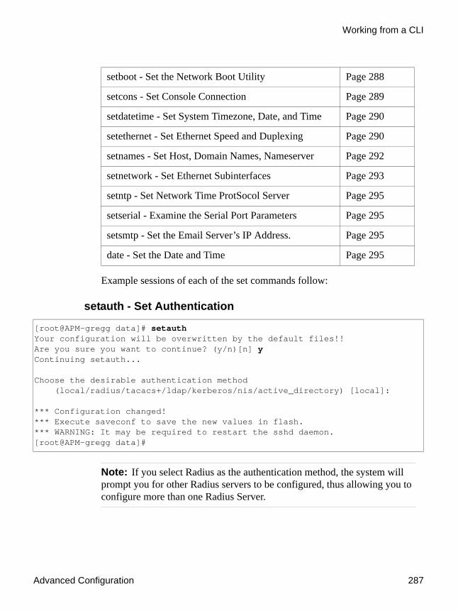
Advanced Configuration 287
Working from a CLI
Example sessions of each of the set commands follow:
setauth - Set Authentication
Note: If you select Radius as the authentication method, the system will prompt you for other Radius servers to be configured, thus allowing you to configure more than one Radius Server.
setboot - Set the Network Boot Utility Page 288
setcons - Set Console Connection Page 289
setdatetime - Set System Timezone, Date, and Time Page 290
setethernet - Set Ethernet Speed and Duplexing Page 290
setnames - Set Host, Domain Names, Nameserver Page 292
setnetwork - Set Ethernet Subinterfaces Page 293
setntp - Set Network Time ProtSocol Server Page 295
setserial - Examine the Serial Port Parameters Page 295
setsmtp - Set the Email Server’s IP Address. Page 295
date - Set the Date and Time Page 295
[root@APM-gregg data]# setauthYour configuration will be overwritten by the default files!!Are you sure you want to continue? (y/n)[n] yContinuing setauth... Choose the desirable authentication method (local/radius/tacacs+/ldap/kerberos/nis/active_directory) [local]: *** Configuration changed!*** Execute saveconf to save the new values in flash.*** WARNING: It may be required to restart the sshd daemon.[root@APM-gregg data]#

Working from a CLI
288 AlterPath Manager Installation, Configuration, and User’s Guide
setboot - Set the Network Boot Utility
[root@APM-gregg root]# setboot Manager Network Boot Configuration Utility-----------------------------------------Current Status: DISABLED Press <ENTER> if you wish to change it, or [Q<ENTER>] to quit: Enter Local IP Address []: <IP_of_APM> Enter Server IP Address []: <IP_of_tftpboot> Enter Kernel Filename []: <kernel_filename> Enter InitRD Filename []: <initRD_filename> WARNING: make sure you're setting valid values for the network boot parameters, or the network boot may not work! Current Status: ENABLED- Local IP Address: <IP_of_APM>- Server IP Address: <IP_of_tftpboot>- Kernel Filename: <kernel_filename>- InitRD Filename: <initRD_filename>Do you wish to save these parameters? (y/N) ySaving network boot configuration ... done.NOTE: the new network boot parameters will be effective after the next reboot.

Advanced Configuration 289
Working from a CLI
setcons - Set Console Connection
[root@APM-gregg root]# setcons APM Console Configuration Utility----------------------------------Current Parameters: 9600, 8n1, vt100 Press <ENTER> if you wish to change it, or [Q<ENTER>] to quit: Enter Baud Rate (in bps) [9600]:Enter Word Length (5, 6, 7 or 8) [8]:Enter Parity (even, odd or no) [no]:Enter Stop Bits (1 or 2) [1]:Enter Terminal Type [vt100]: WARNING: make sure you're setting valid values for the console parameters, or you may make your console inaccessible! Current Parameters: 9600, 8n1, vt100 Do you wish to save these parameters? (y/N) ySaving console configuration ... done.NOTE: the new console parameters will be effective after the next reboot.

Working from a CLI
290 AlterPath Manager Installation, Configuration, and User’s Guide
setdatetime - Set System Timezone, Date, and Time
setethernet - Set Ethernet Speed and Duplexing
Note: Gigabit Ethernet is available on the APM 2500 and APM 5000 only.
[root@APM-gregg root]# setdatetimePlease choose the time zone where this machine is located. 1) Africa 18) Eire 35) Jamaica 52) ROC 2) America 19) Etc 36) Japan 53) ROK 3) Antarctica 20) Europe 37) Kwajalein 54) Singapore 4) Arctic 21) Factory 38) Libya 55) SystemV 5) Asia 22) GB 39) MET 56) Turkey 6) Atlantic 23) GB-Eire 40) MST 57) UCT 7) Australia 24) GMT 41) MST7MDT 58) US 8) Brazil 25) GMT+0 42) Mexico 59) UTC 9) CET 26) GMT-0 43) Mideast 60) Universal10) CST6CDT 27) GMT0 44) NZ 61) W-SU11) Canada 28) Greenwich 45) NZ-CHAT 62) WET12) Chile 29) HST 46) Navajo 63) Zulu13) Cuba 30) Hongkong 47) PRC 64) iso3166.tab14) EET 31) Iceland 48) PST8PDT 65) posix15) EST 32) Indian 49) Pacific 66) posixrules16) EST5EDT 33) Iran 50) Poland 67) right17) Egypt 34) Israel 51) Portugal 68) zone.tabEnter the number corresponding to your choice: 48Current system date and time is: Wed Aug 31 20:03:15 PDT 2005Press ENTER to accept it or specify new ones.Enter date in MM/DD/YYYY format: 08/31/2005Enter time in HH:MM format: 20:07Wed Aug 31 20:07:00 PDT 2005 *** Configuration changed!*** Execute saveconf to save the new values in flash.[root@APM-gregg root]# saveconfSaving configuration files to flash (/flash/config/config.tgz)... done.

Advanced Configuration 291
Working from a CLI
Note: Ethernet and other expansion cards are not supported on the APM 2500.
[root@APM-gregg root]# setethernetCurrent Ethernet eth0 speed/duplex settings: AUTOChange Ethernet eth0 speed/duplex: (Y)es or (N)o ? [N]: yChoose the correct operation mode: 1) Auto-negotiation 2) 10 Mbps, full duplex 3) 10 Mbps, half duplex 4) 100 Mbps, full duplex 5) 100 Mbps, half duplex 6) 1000 Mbps, full duplex 7) 1000 Mbps, half duplexEnter the number corresponding to your choice [1]: 1Enabling auto-negotiation for eth0.Current Ethernet eth1 speed/duplex settings: AUTOChange Ethernet eth1 speed/duplex: (Y)es or (N)o ? [N]: yChoose the correct operation mode: 1) Auto-negotiation 2) 10 Mbps, full duplex 3) 10 Mbps, half duplex 4) 100 Mbps, full duplex 5) 100 Mbps, half duplex 6) 1000 Mbps, full duplex 7) 1000 Mbps, half duplexEnter the number corresponding to your choice [1]: 1Enabling auto-negotiation for eth1. *** Configuration changed!*** Execute saveconf to save the new values in flash.Do you want to make these changes effective now (y/n)? y Configuring eth0 speed/duplex...Configuring eth1 speed/duplex...

Working from a CLI
292 AlterPath Manager Installation, Configuration, and User’s Guide
setnames - Set Host, Domain Names, Nameserver
Caution: All network settings should be changed through the appropriate set scripts. To ensure the name server is correctly set, use “setnames” and run “saveconf” to save the new values in flash.
You can verify that the domain name server is configured correctly on your APM by entering the following command from the console:
# nslookup <your_APM_IP_address>
or
# nslookup <your_APM_host_and_domain_name>
The console display will appear something like the following:
[root@APM-gregg root]# setnamesEnter the System's Hostname (max 30 characters) [APM]: Accounting-APMEnter the System's Domain Name (max 60 chars) [localdomain]: cyclades.comEnter the Primary Nameserver's IP address [none]: 192.168.44.21Enter the Secondary Nameserver's IP address [none]: *** Configuration changed!*** Execute saveconf to save the new values in flash.
[root@APM-gregg root]# nslookup 192.168.48.162Name: backup.cyclades.comAddress: 192.168.44.21 Name: APM-gregg.cyclades.comAddress: 192.168.48.162

Advanced Configuration 293
Working from a CLI
setnetwork - Set Ethernet Subinterfaces
At this point, if the Ethernet default gateway is already configured, the
[root@APM-gregg root]# setnetworkShow current configuration: (Y)es or (N)o ? [N]: nEnable Ethernet Bonding: (Y)es or (N)o ? [N]: nEthernet eth0 IP address: (S)tatic, (D)HCP, (N)one or (K)eep current ? [K]: sEnter Ethernet eth0 IP address: 192.168.48.162Enter Ethernet eth0 Subnet Mask: 255.255.252.0Ethernet eth1 IP address: (S)tatic, (N)one or (K)eep current ? [K]: sEnter Ethernet eth1 IP address: 10.10.10.2Enter Ethernet eth1 Subnet Mask: 255.255.0.0Configure Ethernet Subinterfaces: (Y)es, (N)o or (L)ist ? [N]: lNumber of Ethernet Subinterfaces already configured: 0Configure Ethernet Subinterfaces: (Y)es, (N)o or (L)ist ? [N]: yEnter the Ethernet number [0-1]: 0Enter the Subinterface index [0-9999]: 1Subinterface eth0:1 IP address: (S)tatic or (N)one ? [S]: sEnter Subinterface eth0:1 IP address: 1.1.1.1Enter Subinterface eth0:1 Subnet Mask: 255.0.0.0Configure more Ethernet Subinterfaces: (Y)es, (N)o or (L)ist ? [N]: nConfigure Ethernet VLANs: (Y)es, (N)o or (L)ist ? [N]: yEnter the Ethernet number [0-1]: 0Enter the VLAN index [0-4094]: 2VLAN eth0.2 IP address: (S)tatic or (N)one ? [S]: sEnter VLAN eth0.2 IP address: 3.3.3.3Enter VLAN eth0.2 Subnet Mask: 255.0.0.0Configure more Ethernet VLANs: (Y)es, (N)o or (L)ist ? [N]: nEthernet Default Gateway: (C)hange or (K)eep current ? [K]: cEnter Ethernet Default Gateway [none]: 192.168.48.1
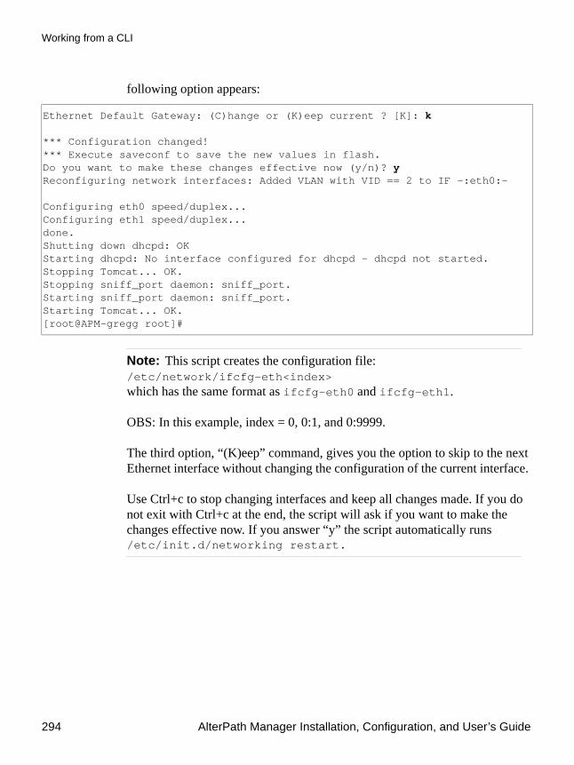
Working from a CLI
294 AlterPath Manager Installation, Configuration, and User’s Guide
following option appears:
Note: This script creates the configuration file: /etc/network/ifcfg-eth<index> which has the same format as ifcfg-eth0 and ifcfg-eth1.
OBS: In this example, index = 0, 0:1, and 0:9999.
The third option, “(K)eep” command, gives you the option to skip to the next Ethernet interface without changing the configuration of the current interface.
Use Ctrl+c to stop changing interfaces and keep all changes made. If you do not exit with Ctrl+c at the end, the script will ask if you want to make the changes effective now. If you answer “y” the script automatically runs /etc/init.d/networking restart.
Ethernet Default Gateway: (C)hange or (K)eep current ? [K]: k *** Configuration changed!*** Execute saveconf to save the new values in flash.Do you want to make these changes effective now (y/n)? yReconfiguring network interfaces: Added VLAN with VID == 2 to IF -:eth0:- Configuring eth0 speed/duplex...Configuring eth1 speed/duplex...done.Shutting down dhcpd: OKStarting dhcpd: No interface configured for dhcpd - dhcpd not started.Stopping Tomcat... OK.Stopping sniff_port daemon: sniff_port.Starting sniff_port daemon: sniff_port.Starting Tomcat... OK.[root@APM-gregg root]#

Advanced Configuration 295
Working from a CLI
setntp - Set Network Time ProtSocol Server
setserial - Examine the Serial Port Parameters
setsmtp - Set the Email Server’s IP Address.
date - Set the Date and Time
Note: Date format is: [MMDDhhmm[[CC]YY].SS]
Changing the Escape SequenceThere are two ways to change the escape sequence:
• Locally: From the console session, use option ^Ece (refer to the table of help above for 'e') to change the escape sequence. It applies only to the current console session. Once you log off, the escape sequence is deleted.
• Globally: Change file /var/apm/bin/con as below. To make it permanent, you must include this file in /etc/files.list and then run saveconf.
[root@APM-gregg root]# setntpEnter the NTP server: 192.168.48.164 *** Configuration changed!*** Execute saveconf to save the new values in flash.
[root@APM-gregg root]# setserial /dev/ttyS0/dev/ttyS0, UART: 16550A, Port: 0x03f8, IRQ: 4
[root@APM-gregg root]# setsmtpEnter the email (SMTP) server: smtp.<your_domain.com> *** Configuration changed!*** Execute saveconf to save the new values in flash.
[root@APM-gregg root]# date 083122552005Wed Aug 31 22:55:00 PDT 2005

Working from a CLI
296 AlterPath Manager Installation, Configuration, and User’s Guide
#original line in /var/apm/bin/conexec /var/apm/bin/console -Mlocalhost -l$USR $1
#modify this line to have -e <escape seq>.
Note: In this example esc seq= ^Az
exec /var/apm/bin/console -Mlocalhost -e^Az -l$USR $1
The result of this change in the console session is as follows:
[arnaldo@hp arnaldo]$[arnaldo@hp arnaldo]$ ssh -ladmin:acs8_02 192.168.47.86Password:Console on-demand, please wait...[Enter `^Az?' for help][Enter `^Az.' to disconnect]
Re-defining the Interrupt KeyThe key sequence Ctrl+c in the file /var/apm/bin/apmrun.sh has been changed to Ctrl+Shift+hyphen (that is: ^_) to prevent the system from directing this command to any application running on the foreground rather than to the console server. Unlike ^c, the latter is not a valid key combination for most servers including Sun, and should enable you to interrupt the console server as necessary.
If, however, you need to re-define the command, you may do so from the/var/apm/bin/apmrun.sh file, below the commented line shown:
# Redefine CTRL+C here. Customize it as you wish.stty intr ^_
To Change the Number of Lines in the SSH Applet
Note: By default, the number of lines used by the memory buffer when a user scrolls the window is set to 1000 lines (Terminal buffer = 1000). You may change this value to suit your needs. Be aware, however, that specifying values greater than 1000 can degrade scroll performance.
1. Edit the file: /opt/tomcat/apm/applet.conf

Advanced Configuration 297
Working from a CLI
2. Locate the line and edit as follows:
Terminal.buffer = [number of lines]
3. Type in saveconf to save your configuration.
4. Close and reopen the applet window to make the change effective.
To Change the Session TimeoutThe default session timeout value is 60 minutes. To change this value, follow the steps below:
1. Edit the file: /opt/tomcat/apm/WEB-INF/web.xml
2. Locate and edit the line:
<session-timeout>60</session-timeout>
3. To make the change effective, reboot or restart tomcat as follows:
# /etc/init.d/tomcat stop# /etc/init.d/tomcat start
To Change the Number of Consoles per PageThe default number of consoles that you can view from the Consoles List form is set to 512. Edit the /var/apm/apm.properties file.
4. Go to the apm.consolesperpage=512 line.
5. Change the “512” in the line to the value desired.
To Enable TelnetTelnet is available in the AlterPath Manager, but disabled by default to avoid security problems. To enable Telnet, follow the steps below:
1. Edit /etc/services and add the following line:
telnet 23/udp
2. Select either step a below to enable the PAM version of telnet or select step b below to enable the Kerberized version of telnet. Do not enable both.

Working from a CLI
298 AlterPath Manager Installation, Configuration, and User’s Guide
a. Edit /etc/xinetd.conf and remove the “#” symbols to from the following section of the file to enable the PAM version of telnet:
b. Edit /etc/xinetd.conf and remove the “#” symbols to from the following section of the file to enable the Kerberized version of telnet
3. Verify that /etc/protocols has the following entries:
tcp 6 TCP # transmission control protocol udp 17 UDP # user datagram protocol
4. If you are going to use PAM support, add the “pts” devices in the file, /etc/securetty as shown below:
# Telnetd with PAM supportservice telnet{ flags = REUSE socket_type = stream wait = no user = root server = /usr/sbin/in.telnetd log_on_failure += USERID disable = no}#
# Kerberized telnetdservice telnet{flags = REUSEsocket_type = streamwait = nouser = rootserver = /usr/kerberos/sbin/telnetdbind = 127.0.0.1log_on_failure += USERID}
ttyS0pts/0pts/1pts/2pts/3pts/4pts/5

Advanced Configuration 299
Sudo Support
5. Enter the command: # saveconf
6. To complete the procedure, restart xinetd with the following command:# /etc/init.d/xinetd restart
Note: xinetd services will be available after reboot, since this script is already included in the startup procedure.
Sudo SupportMost AlterPath devices support sudo (Super User Do) commands. This allows admin users of these devices to invoke a limited number of commands ordinarily reserved for root users. It also allows such users to perform configuration tasks on the devices on which they are assigned via the CLI applet or CLI JWS from the APM.
The root user of the device is also able to limit the access to that device by the APM administrator while still allowing the APM administrator to configure the device’s consoles, upload the configurations, and use autodiscover.
Sudo is implemented for the user “admin” in the following devices:
• ACS - Version 2.6.1 and greater• TS - TBD• KVM/net - All versions• KVM/net+ - All versions• OnBoard 1.1.0 or greater (not supported on APM 1.4.1 or earlier).• OnSite - 1.1.0 or greater
How to Verify sudo1. Log on to the APM as “admin” and edit the device you want to check
2. From the “Device Details” form, enter “admin” in the field for the name of the admin user.
3. Set the password for the user “admin”. Be sure it matches the password that is assigned to “admin” on the device.
4. Click the “Save” button at the bottom of the screen.

Ethernet Bonding
300 AlterPath Manager Installation, Configuration, and User’s Guide
The device list appears.
5. Click the name of the device in the list, and then select the CLI applet or the CLI JWS.
The terminal emulator will appear shortly. You will be logged on to the device as “admin”.
6. Enter the following commands from the shell prompt on the terminal:
# reboot (should not cause a reboot)
# sudo reboot (should cause a reboot of the device and a 2-minute timeout-reconnect sequence of the terminal)
Note: Some early versions of KVM/net software might require you to enter this command with the full pathname: # sudo /sbin/reboot
Ethernet BondingEthernet bonding is a method of providing redundancy to an Ethernet connection. When Ethernet bonding is enabled, the primary Ethernet port operates under normal circumstances. If the primary Ethernet port fails, a backup (or redundant) Ethernet port takes over. This is called a failover condition (e.g., the primary Ethernet port fails over to the secondary Ethernet port). A different interface becomes active if, and only if the active interface fails. After a failover has occurred, the primary interface becomes active once again after the failover condition has been corrected.
Note: The AlterPath Manager Ethernet bonding implementation is not limited to two Ethernet interfaces, but only one interface in the bond will be active at any given time.
Note: DHCP for bond interfacing is not supported.
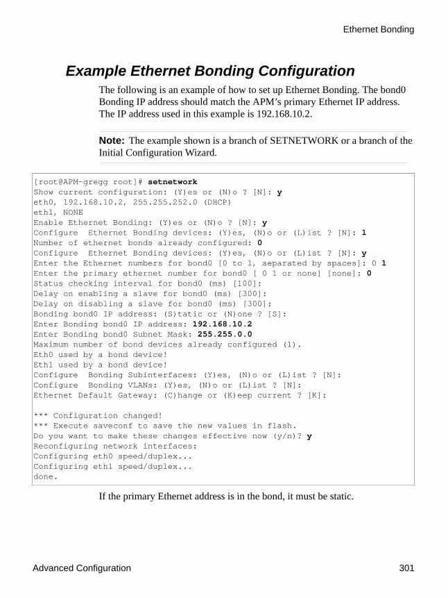
Advanced Configuration 301
Ethernet Bonding
Example Ethernet Bonding ConfigurationThe following is an example of how to set up Ethernet Bonding. The bond0 Bonding IP address should match the APM’s primary Ethernet IP address. The IP address used in this example is 192.168.10.2.
Note: The example shown is a branch of SETNETWORK or a branch of the Initial Configuration Wizard.
If the primary Ethernet address is in the bond, it must be static.
[root@APM-gregg root]# setnetworkShow current configuration: (Y)es or (N)o ? [N]: yeth0, 192.168.10.2, 255.255.252.0 (DHCP)eth1, NONEEnable Ethernet Bonding: (Y)es or (N)o ? [N]: yConfigure Ethernet Bonding devices: (Y)es, (N)o or (L)ist ? [N]: lNumber of ethernet bonds already configured: 0Configure Ethernet Bonding devices: (Y)es, (N)o or (L)ist ? [N]: yEnter the Ethernet numbers for bond0 [0 to 1, separated by spaces]: 0 1Enter the primary ethernet number for bond0 [ 0 1 or none] [none]: 0Status checking interval for bond0 (ms) [100]:Delay on enabling a slave for bond0 (ms) [300]:Delay on disabling a slave for bond0 (ms) [300]:Bonding bond0 IP address: (S)tatic or (N)one ? [S]:Enter Bonding bond0 IP address: 192.168.10.2Enter Bonding bond0 Subnet Mask: 255.255.0.0Maximum number of bond devices already configured (1).Eth0 used by a bond device!Eth1 used by a bond device!Configure Bonding Subinterfaces: (Y)es, (N)o or (L)ist ? [N]:Configure Bonding VLANs: (Y)es, (N)o or (L)ist ? [N]:Ethernet Default Gateway: (C)hange or (K)eep current ? [K]: *** Configuration changed!*** Execute saveconf to save the new values in flash.Do you want to make these changes effective now (y/n)? yReconfiguring network interfaces:Configuring eth0 speed/duplex...Configuring eth1 speed/duplex...done.

Configuration of DHCP Client in APM
302 AlterPath Manager Installation, Configuration, and User’s Guide
Configuration of DHCP Client in APMNote: You cannot use DHCP if you are including Eth0 as part of an Ethernet bond.
When you configure the network, either through the First Time Configuration Wizard, or through the CLI “setnetwork” command, you now have the option to use DHCP (Dynamic Host Configuration Protocol) to configure Eth0. DHCP allows the APM to obtain its own IP address from the DNS server. If there is no DNS server, or if the DNS server cannot be accessed, a default IP address of 192.168.1.20 will be assigned to Eth0. Eth0 is the only Ethernet port that can be configured to use DHCP.
Example DHCP Configuration
Note: The example shown is a branch of setnetwork or a branch of the Initial Configuration Wizard.
If the Ethernet default gateway is already configured, the following option appears:
Enable Ethernet Bonding: (Y)es or (N)o ? [N]: nEthernet eth0 IP address: (S)tatic, (D)HCP or (N)one ? [S]: dEthernet eth1 IP address: (S)tatic or (N)one ? [S]: sEnter Ethernet eth1 IP address: 10.10.10.2Enter Ethernet eth1 Subnet Mask: 255.255.0.0Configure Ethernet Subinterfaces: (Y)es, (N)o or (L)ist ? [N]: lNumber of Ethernet Subinterfaces already configured: 0Configure Ethernet Subinterfaces: (Y)es, (N)o or (L)ist ? [N]: nConfigure Ethernet VLANs: (Y)es, (N)o or (L)ist ? [N]: nEnter Ethernet Default Gateway [none]: 192.168.48.1
Ethernet Default Gateway: (C)hange or (K)eep current ? [K]: k *** Configuration changed!*** Execute saveconf to save the new values in flash.Do you want to make these changes effective now (y/n)? y

Advanced Configuration 303
Ethernet Port Configuration
Ethernet Port ConfigurationThe Ethernet hardware has commands to control the link speed and duplex supported on each interface.
There is a script named “setethernet” that is invoked automatically along with the other initial APM configuration the first time the APM is run (see “First Time Configuration Wizard” on page 92).The setethernet script can also be run by the administrator manually from the console at any time.
Refer to “setethernet - Set Ethernet Speed and Duplexing” on page 290 for details on configuring the Ethernet port.
Note: Gigabit Ethernet is available on the APM 2500 and APM 5000 only.
HP OpenView NNM IntegrationThe HP OpenView Integration Module (IM) is a Cyclades product that links the AlterPath System to the HP OpenView systems management platform. In order for the IM to work, the AlterPath Manager must contain the NNM license. See the “AlterPath Integrator for HP OV NNM B.07.50 Integration Guide” (PAC0436) for details on this product.
Modem Card ConfigurationNote: Modems are not supported on the APM 2500 or the APM 5000.
The AlterPath Manager is equipped with modem dialing capability, allowing complete out-of-band access to remote console server devices. This section provides basic procedures for configuring the card through a command line interface.
Checking Your ModemsThe four modems are detected during bootup. All modem devices present are included automatically in the modem pool. To view which modems are in use or which ones are available, use SSH to connect to the AlterPath Manager, login as “root”, and use the following commands:

Modem Card Configuration
304 AlterPath Manager Installation, Configuration, and User’s Guide
# check_modem ( -d | -s ) [tty]
Where: -d disconnect-s status[tty] If no tty is specified, then the command applies to all modems.
To check what modems are available, type in: check_modem -s
Example:
[root@APM root]# check_modem -sttyPS0 AvailablettyPS1 AvailablettyPS2 AvailablettyPS3 Available
To Exclude Modems from the Modem PoolIf your configuration requires less than four modems, then you must exclude the unnecessary modem(s) from the pool to prevent a dial-up failure. When you exclude modems, be sure to run and save your configuration as follows:
1. Using VI, edit the following file:
# vi /var/apm/apm.properties
2. Type in: modem.pool.exclude=ttyPS[#]
For example, to exclude ttyPS2 and ttyPS3, type in: modem.pool.exclude=ttyPS2 ttyPS3
3. Once a modem has been excluded, you must initialize the configuration by typing in: /etc/init.d/modem_pool restart
Warning! Be sure that no upload is in progress when you run this command otherwise all PPP connections will be disconnected. The same is true when disconnecting a modem (check_modem -d <tty>).
4. To save your configuration to flash, type in: saveconf
5. Verify your new configuration by typing in: check_modem -s

Advanced Configuration 305
Serial Card Configuration
Viewing the Latest Status for Each ModemThe modems in the modem pool are allocated in a round robin sequence to ensure all modems are exercised to the same degree. If a modem fails to dial out, the system will allocate the next modem in the modem pool.
The /var/log/modem_status file contains the result of the last attempted usage of a modem. Containing the modem, date, time, and status, it is created the first time a connection is attempted.
Example:
[root@APM root]# cat /var/log/modem_statusttyPS0 2004/04/12 09:40:12 Dial out to acs48failedttyPS1 2004/04/12 09:42:35 Connected to acs32ttyPS2 2004/04/12 09:32:23 Connected to acs32ttyPS3 2004/04/12 09:35:00 Dial out to acs48 failed:NO DIAL TONE
Serial Card ConfigurationThe AlterPath Manager supports the use of a PCI-based multi-port serial cards. The cards are used to connect the AlterPath Manager to external modems. Up to eight serial devices are created if modems are connected to serial ports and the devices are names ttyPS0-ttyPS7
This section provides basic procedures for configuring the card through a command line interface.
How to Detect Modems Connected to the Ports
Note: Modems are currently supported on the APM E2000 only.
To detect a modem connected to a serial port, ensure that the modem is powered ON during system boot of the AlterPath Manager. If one or more modems are connected after the AlterPath Manager is running, you must use the following command:
# /etc/init.d/modem_pool restart

Serial Card Configuration
306 AlterPath Manager Installation, Configuration, and User’s Guide
Warning! This command will disconnect all modems that are in use.
Checking Your ModemsAll modems that are powered ON are included automatically in the modem pool. To view which modems are in use or which ones are available, use SSH to connect to the AlterPath Manager, login as “root”, and use the following commands:
# check_modem ( -d | -s ) [tty]
Where: -d disconnect-s status[tty] If no tty is specified, then the command applies to all modems.
To check what modems are available, type in: check_modem -s
Example:
[root@APM root]# check_modem -sttyPS0 AvailablettyPS1 AvailablettyPS2 AvailablettyPS3 Available
Viewing the Latest Status of Each ModemThe modems in the modem pool are allocated in a round robin sequence to ensure all modems are exercised to the same degree. If a modem fails to dial out, the system will allocate the next modem in the modem pool. The “/var/log/modem_status” file contains the result of the last attempted usage of a modem. Containing the modem, date, time, and status, it is created the first time a connection is attempted.
Example:
[root@APM root]# cat /var/log/modem_statusttyPS0 2004/04/12 09:40:12 Dial out to acs48failedttyPS1 2004/04/12 09:42:35 Connected to acs32ttyPS2 2004/04/12 09:32:23 Connected to acs32ttyPS3 2004/04/12 09:35:00 Dial out to acs48 failed:NO DIAL TONE

Advanced Configuration 307
Configuring Dial Out and Dial Back
To Define Different Scripts for Each tty DeviceThe modem chat scripts are located in “/etc/ppp”, and are used by “pppd” to initialize the modem and to dial out.
The file, “/etc/ppp/chat-init” is the default script used for modem initialization and “/etc/ppp/chat-connect” is the default script for modem dial out.
1. To define an init script for a specific port, copy “/etc/ppp/chat-init” as “/etc/ppp/chat-init-<tty device>”.
Where: <tty device> is the port where you want to apply the script.
For example, if “/etc/ppp/chat-init-ttyPS0” is present, then the system uses this file instead of “/etc/ppp/chat-init” to initialize ttyPS0.
2. To define a connect script for a specific port, copy “/etc/ppp/chat-connect” as: “/etc/ppp/chat-connect-<tty device>”.
For example, if “/etc/ppp/chat-connect-ttyPS0” is present, then the system uses this file instead of “/etc/ppp/chat-connect” to dial out through ttyPS0.
3. Add the new file names in “/etc/files.list”
4. Enter saveconf to save your configuration.
Configuring Dial Out and Dial BackTo enable device or console access through dial out or dial back, you must configure the following:
Note: For a complete list of all configuration requirements for Dial Out and Dial Back, see “Dial Up and Dial Back” on page 127.
For ACS Devices:Using CLI, create a new user and password from the ACS using the commands:
• adduser <ppp_user>
• passwd <ppp_user>

Modem Dial Back for ACS
308 AlterPath Manager Installation, Configuration, and User’s Guide
Modem Dial Back for ACSThe dial back feature, which is configurable from the web interface, is designed to enable the AlterPath Manager to automatically dial to a remote ACS unit should the network fail, and enable the ACS to dial back the connection.
Required CLI configurationThis dial back feature is configured mostly from the web interface (Admin Mode, Devices > Dial Up). There are, however, three parameters that you must configure from the CLI:
• From the ACS, create a user by using the Linux command and syntax: # adduser <ppp_user>
Note: This must be the same PPP user configured in the AlterPath Manager “Dial Up” form.
• Also from the ACS, set the password for the ppp_user in the ACS using the command and syntax: # passwd <ppp_user>
Note: This must be the same PPP password configured in the AlterPath Manager “Dial Up” form.
• From the AlterPath Manager, go to “/var/apm/apm.properties” file and add the APM phone number in the parameter: dial.apm_phone_number=<phone_number>
Note: The AlterPath Manager allows only one phone number for this parameter so that there is a hunt group configured to point to only one phone number.
Optional CLI ConfigurationThe following parameters (with examples) are OPTIONAL:

Advanced Configuration 309
Modem Dial Back for ACS
From the AlterPath Manager, edit the file: “/var/apm/apm.properties” to:
• Define the PPP idle timeout (in seconds).ppp.idle=600
• Exclude modems from the modem pool by listing the modems to be excluded.modem.pool.exclude=ttyPS2 ttyPS3
• Select modems that will never be used for dial-in by listing them as follows:modem.pool.out_only=ttyPS1 ttyPS3
• Configure timeout to wait for a dial-back call from an ACS: modem.pool.dial_in_timeout=30
If a timeout value is not provided, the AlterPath Manager will wait for 60 seconds.
• Define the time (in seconds) in which the AlterPath Manager should wait before allocating the modems for dial-in after receiving a confirmation from an ACS that it will call the AlterPath Manager back. modem.pool.on_hook_time=4
For external modems:From the ACS, edit the file “/etc/inittab” and “/etc/pslave.conf” to:
• Remove the control of Portslave over it, and add mgetty.
For PCMCIA modem:From the ACS, copy the file:
“/etc/ppp/options.ttySn”
to:
“/etc/ppp/options.ttyS(n+1)”
Where: “n” is the number of the last serial interface of your ACS (i.e., 1 for ACS1, 8 for ACS8, etc).
For PCMCIA modems, no further configuration is required; just insert the modem card and mgetty will open the modem port and wait for the ring.

Modem Dial Back for ACS
310 AlterPath Manager Installation, Configuration, and User’s Guide
ISDN Configuration
Note: Be sure you perform a configuration upload to the ACS after you finish configuring the following parameters.
Additional parameters in the AlterPath Manager’s /var/apm/apm.properties file that need to be configured for supported ISDN modems include the following:
• Specify an ISDN protocol in this line:isdn.protocol= (if empty, ETSI is assumed)
Or:
isdn.protocol=<protocol>
Note: To view a list of protocols, enter this command at the shell prompt:# divactrl load -h
• For concurrent, dialout-only ISDN sessions, the APM uses a different multiple subscriber number (MSN) for each connection. Specify a pool of MSNs in the following line:isdn.msnpool=<MSN1>[,<MSN2>, . . .]
• For concurrent, dialout with callback ISDN sessions, specify the MSNs in the following line:isdn.inmsn=<MSN3>[,<MSN4>, . . .]
Note: MSNs entered in the “isdn.inmsn=” field always enable dialout with callback, even if they are entered in the “isdn.msnpool=” field.
• If a multiport ISDN card, such as the Eicon Diva Server 4BRI-8M is used, (or multiple single-port cards, such as the Eicon Diva Server BRI-2M) you will need to configure the following parameter:
isdn.ctrlmsnmap=<controller_1><MSN5>[,<MSN6> <controller_2><MSN7>,<MSN8> . . .] (where MSN5 through MSN8 are the local phone numbers to which the controllers (or ports) are connected)

Advanced Configuration 311
Changing the Ports to be Proxied
Sample ISDN Configuration
Be sure to perform a configuration upload to the ACS after you have configured the parameters shown above.
Changing the Ports to be ProxiedWhen Forward Proxy (with or without ARP) is enabled for a device, the default proxied ports are 80 and 443. To change the opened ports, perform the following steps:
1. Edit the property proxyserver.ports in the /var/apm/apm.properties file.
2. Separate the port numbers using commas. There should be no spaces in this line.
Example:
proxyserver.ports=80,443,8080
NIS ConfigurationTo use NIS authentication, NIS is selected from the First Time Configuration script. To further control NIS authentication, edit the following configuration file as follows:
File to edit: /etc/nsswitch.conf
.
.
.isdn.protocol=5ESSisdn.msnpool=5551212,5551213isdn.inmsn=5551214,5551215# Configures the mapping of MSN phone numbers to the ISDN controllers# (usually maximum of 2 MSN, i.e 2 b-channels per ISDN controller)# The ISDN controllers available can be found in /proc/capi/controller# Syntax: isdn.ctrlmsnmap=<controller no.>:<MSN1>[,<MSN2>...] ...isdn.ctrlmsnmap=1:5551215,5551216 2:5551217,5551218...

NIS Configuration
312 AlterPath Manager Installation, Configuration, and User’s Guide
Format: <database>:<service>[<actions><service>]
What the status messages mean:
NIS User AuthenticationTo use NIS only to authenticate users, change the lines about passwd, shadow and group in the configuration file (/etc/nsswitch.conf) as described below.
Where: Parameter Definition:
<database> Available: aliases, ethers, group, hosts, netgroup, network, passwd, protocols, publickey, rpc, services, and shadow.
<service> Available: nis (use NIS version 2), dns (use Domain Name Service), and files (use the local files).
<actions> this syntax has this format: [<status>=<action>]
WHERE:<status> = SUCCESS, NOTFOUND,
UNAVAIL, or TRYAGAIN
<action> = RETURN or CONTINUE
Status: Meaning:
SUCCESS No error occurred and the desired value is returned. The default action for this status is return.
NOT FOUND The lookup process works, but the needed value was not found. The default action for this status is continue.
UNAVAIL The service is permanently unavailable.
TRYAGAIN The service is temporarily unavailable.

Advanced Configuration 313
NIS Configuration
The AlterPath Manager does not support user authentication against a NIS map and the local file (/etc/passwd) at the same time. Either the user is present in the NIS map or in the passwd file, but not both. The AlterPath Manager will not even allow you to add a user in the local database if the user is already present in the NIS server.
The configuration below enables the system to authenticate NIS users and local users.
Authenticate the user first through the local database and if the user is not found, use NIS.
passwd: files compatshadow: files compatgroup: files compat
passwd_compat: nisshadow_compat: nisgroup_compat: nis
Authenticate the user first through NIS and if the user is not found, use the local database.
passwd: compat filesshadow: compat filesgroup: compat files
passwd_compat: nisshadow_compat: nisgroup_compat: nis
Authenticate the user first through NIS, and if the user is not found or the NIS server is down, use the local database.
passwd: compat [UNAVAIL=continue TRYAGAIN=continue] filesshadow: compat [UNAVAIL=continue TRYAGAIN=continue] filesgroup: compat [UNAVAIL=continue TRYAGAIN=coninue] file
passwd_compat: nisshadow_compat: nisgroup_compat: nis

Creating the krb5.keytab for Kerberos Authentication
314 AlterPath Manager Installation, Configuration, and User’s Guide
Creating the krb5.keytab for Kerberos Authentication
The AlterPath Manager supports kerberized networks. Kerberos is a computer network authentication protocol designed for insecure networks based on the key distribution model. It allows individuals communicating over a network to prove their identity to each other while also preventing eavesdropping or replay attacks. It also detects modifications and prevents unauthorized reading.
How Kerberos WorksOn a kerberized network, the Kerberos database contains principals and their keys (for users, their keys are derived from their passwords). The Kerberos database also contains keys for all of the network services.
When a user on a kerberized network logs in to their workstation, their principal is sent to the Key Distribution Center (KDC) as a request for a Ticket Granting Ticket (TGT). The login program sends the request (so that it is transparent to the user) or the kinit program sends it after the user logs in.
The KDC checks for the principal in its database. If the principal is found, the KDC creates a TGT, encrypts it using the user's key, and sends it back to the user. The login program or kinit decrypts the TGT using the user's key (which it computes from the user's password). The TGT, which is set to expire after a certain period of time, is stored in your credentials cache.
An expiration time is set so that a compromised TGT can only be used for a certain period of time, usually eight hours (unlike a compromised password, which could be used until changed). The user will not have to re-enter their password until the TGT expires or they logout and login again.
When the user needs access to a network service, the client uses the TGT to request a ticket from the Ticket Granting Service (TGS) which runs on the KDC. The TGS issues a ticket for the desired service which is then used to authenticate the user.
Creating the krb5.keytab in the AlterPath ManagerThe AlterPath Manager automatically creates “krb5.conf”, the file that holds information about KDC addresses and port numbers. The user, however, must

Advanced Configuration 315
Creating the krb5.keytab for Kerberos Authentication
create the “/etc/krb5.keytab” file, a binary file that holds the cryptographic keys to validate the Kerberos tickets received.
There are two different ways to get the “/etc/krb5.keytab” file into the AlterPath Manager.
Method 1:
Using SCP, copy the “/etc/krb5.keytab” file from the Kerberos Key Distribution Center (KDC), also known as the Kerberos Server.
Method 2:
Connect to the Kerberos database by executing the command: # kadmin -p <principal>
This is an interactive program; it will ask for the password for the principal used to connect to the Kerberos database.
After successful connection, run ktadd command for each principal required in order to add its respective cryptographic keys of that principal to the keytab file. Both the client host and the users supposed to be authenticated must have entries in the keytab file.
You can explicitly indicate which file to be used as keytab by using the “-k” option.
For example:
ktadd -k /etc/krb5.keytab host/apm.somedomainktadd -k /etc/krb5.keytab nestorktadd -k /etc/krb5.keytab guest
If the desirable principal was not yet added to the Kerberos database, they should be added with addprinc command before executing ktadd.
For example:
addprinc -randkey host/apm.somedomainaddprinc nestoraddprinc guest

Active Directory (with LDAP)
316 AlterPath Manager Installation, Configuration, and User’s Guide
Active Directory (with LDAP)
To Configure Active Directory
Note: This procedure can either be invoked through the First Time Configuration Wizard, or from the “setauth” command.
1. Choose the “active_directory” authentication method at the following prompt:(local/radius/tacacs+/ldap/kerberos/nis/active_directory) [local]: active_directory
2. Enter the Active Directory server: <authserver>
3. Enter the distinguished name of the search base:(ex: 'dc=cyclades,dc=com'): dc=<first_part_domain_name>,dc=<second_part_domain_name>
Note: The second part of the domain name is usually “.com,” “.net,” “.org,” etc.
4. Enter the common name to bind to the server:(ex:'cn=Administrator,cn=Users,dc=cyclades,dc=com'): <user>@<authserver>
5. Enter the password to bind with:
6. Re-enter the password:
If the procedure was invoked from “setauth”, the following messages will be displayed:*** Configuration changed!
*** Execute saveconf to save the new values in flash.
*** WARNING: It may be required to restart the sshd daemon.
[root@APM_2500 root]#

Advanced Configuration 317
Open LDAP
Open LDAP
To Configure Open LDAP
Note: This procedure can either be invoked through the First Time Configuration Wizard, or from the “setauth” command.
1. Choose the “ldap” authentication method at the following prompt:(local/radius/tacacs+/ldap/kerberos/nis/active_directory) [local]: ldap
2. Enter the name or IP address of the LDAP server at the prompt:Enter the LDAP server: <LDAP_server_name>
3. Enter the server’s LDAP base at the prompt:(ex: 'dc=cyclades,dc=com', 'ou=person,o=cyclades'):dc=<first_part_domain_name>,dc=<second_part_domain_name>
Note: The second part of the domain name is usually “.com,” “.net,” “.org,” etc.

Open LDAP
318 AlterPath Manager Installation, Configuration, and User’s Guide
If the procedure was invoked from “setauth”, the following messages will be displayed:*** Configuration changed!
*** Execute saveconf to save the new values in flash.
*** WARNING: It may be required to restart the sshd daemon.
[root@APM_2500 root]#

Advanced Configuration 319
Disabling HTTP to use only HTTPS
Disabling HTTP to use only HTTPSThe AlterPath Manager is configured to allow both HTTP and HTTPS access. For greater security, you can disable HTTP access to allow only HTTPS.
To Disable HTTP to Use Only HTTPS1. Edit the file: “/usr/conf/httpd-std.conf”
2. Comment out the listen directive: #Listen 80
3. To make the configuration effective, restart tomcat and apache by first stopping tomcat followed by apache, and then starting apache followed by tomcat:
# /etc/init.d/tomcat stop# /etc/init.d/apache stop# /etc/init.d/apache start# /etc/init.d/tomcat start
4. Use the saveconf command to save the configuration.
Note: If you disable HTTP, you must still type “https” in the browser URL input field to access the APM using the WMI. There is no automatic redirection to HTTPs.
Firmware
To Add FirmwareFirmware files (.tgz) are normally downloaded from the web and copied into the AlterPath Manager using Secure Copy (SCP). To add or import new firmware, follow this procedure:
1. From the web (www.cyclades.com), download the firmware to the server you use to store your firmware.
2. Connect to the AlterPath Manager from your server using SSH.
3. Use the “scp” command to copy the firmware to the AlterPath Manager from your server.

Firmware
320 AlterPath Manager Installation, Configuration, and User’s Guide
Example: scp v214.tgz root@<ip_address>:/usr/fw
4. From the WMI, open the Firmware List form and click the “Import” button.
The system should add the new firmware on the Firmware List form. The system also updates the Firmware/Boot drop down list in the Device Definition form.
To Upgrade the APM FirmwareYou may upgrade the AlterPath Manager firmware by downloading the upgraded software from the web to the AlterPath Manager.
Note: After you upgrade the APM firmware, you should clear the cache of your web browser and then restart your web browser. This will ensure that the browser will not attempt to use a previously opened session or attempt to use any cached static resources.
1. From the Cyclades website (www.cyclades.com), download and copy the firmware to the server you want to use to store firmware for the AlterPath Manager.
The firmware is composed of two files:
• all.tgz• all.tgz.md5sum
2. From your firmware server, copy the two files to the AlterPath Manager /tmp directory as follows:
# scp all.tgz root@APM_IP:/tmp# scp all.tgz.md5sum root@APM_IP:/tmp
3. Login to the AlterPath Manager console as “root”, and then change the directory to “/tmp” as follows:
# ssh root@APM_IP# cd /tmp
4. Install the new software to compact flash as follows:
# installimg all all.tgz
5. reboot

Advanced Configuration 321
Backing Up User Data
Caution: Licenses (except for factory default licenses) must be reinstalled after you recreate the system partition or after you run the “installimg” command.
If you want to preserve your licenses before you recreate a system partition or before you run “installimg,” you can edit the file “/etc/files.list” and add your license file name to the list of files. Be sure to use the full path of each license file name you enter into this file. For example if the name of the license file you are adding is “APM_B_IPMI.enc” you should enter the full path name:var/apm/licenses/data/APM_B_IPMI.encBe sure to follow up with the “saveconf” command. It is also a good idea to save a copy of each license file on a server that can be accessed by your APM, just to be extra safe.
If at any time you run “defconf” the file, “/etc/files.list” will revert back to its original state, and you will need to reinstall your license.
Backing Up User DataUsing CLI, you can back up and restore the configuration and data files of the AlterPath Manager to a local or a remote destination. This feature allows you to backup and restore (either independently or altogether) the following data types: Table 5-4: Data Types You Can Backup and Restore
Data Type Definition
System Configuration Data related to the AlterPath Manager host settings such as IP Address, Authentication Type, and Host Name.
Configuration Data Data related to the configuration of consoles, users and so forth, which are stored in the database.
Data Buffers The ASCII data collected from the consoles.

Managing Log Files
322 AlterPath Manager Installation, Configuration, and User’s Guide
Backup and Restore ScenariosFor illustration purposes, there are two scenarios in which you can perform the backup.
• Replicating data to a hot spare machine - You back up the configuration data and data buffers and restore them to a second AlterPath Manager unit. This method enables you to keep the network identity of each AlterPath Manager unit, but maintain the same configuration for both units. The second unit serves as a spare system.
• Replacing the existing AlterPath Manager - You back up ALL data to an external server. The AlterPath Manager is then replaced with a new unit to which all data is restored. The new unit will have the same configuration as the original unit.
Backup and Restore CommandsFrom the CLI at the Linux shell prompt, the command lines for backup and restore are as follows:
If you do not specify a user, then the system uses the current username.
If you do not specify a host, then the system creates a backup on the local host, or executes a restore from the local host.
The backup/restore operations use secure copy (scp). The file is saved as a tar file (*.tgz).
Note: You must reboot after you execute either the “restore sys” command or the “restore all” command.
Managing Log FilesWhere Log Files are Archived
Once log files are rotated, the system stores them in:
/var/log/consoles/rotated
# backup {log | sys[tem] | conf[iguration] | all} [[user@]host:]file# restore {log | sys[tem] | conf[iguration] | all} [[user@]host:]file
Advanced Configuration 323
System Recovery Guidelines
You can back up these files to another server using the secure shell SCP program.
Backing Up Log Files to a Remote ServerYou can copy rotated logs to another server that is more suited for holding large amounts of log data using the following command line syntax:
save_rotated_log [[user@]host:]file [-flush] [-now]
Where:
-flush deletes the current rotated logs
-now forces an immediate log rotation
The destination file is mandatory and must be the first argument. The order of the options (“-flush” and “-now”) does not matter; the system will perform the actions in the same order (save-flush-rotate) regardless of the options given.
If you supply user@host, the logs are transferred to a remote machine under the privileges of the specified user. If you do not supply user@, the system will assume that the current user is the remote one.
For remote destination, ensure that the remote machine is prepared to accept connections to ssh service on port 22. If only the file name is supplied, the system will copy the logs locally. You can include path names as part of the file name.
System Recovery GuidelinesIn the event that the AlterPath Manager goes down, the system will check the integrity of the file system during the restart. If a problem is found, then the system will attempt to repair any damage that may have occurred.
When performing a recovery procedure, if there is too much damage, you have the option to stop the booting process and take recovery actions through the serial console as follows:
1. Rebuild system partition
2. Rebuild database
3. Rebuild data log partition
Root Password Recovery
324 AlterPath Manager Installation, Configuration, and User’s Guide
The rest of the configuration process is done through the GUI/web interface.
If the AlterPath Manager goes down, you will still have direct access to ports and consoles, but you will need to redefine the devices.
Root Password RecoveryIn the event of a forgotten or mis typed root password, the APM’s main system administrator (e.g., the root user) will need create a new password. The root user is the only user who has this capability.
To Recover a Root Password
Caution: This is a security issue! This procedure can be performed by anyone with physical access to the APM’s serial console port.The only way to prevent an unauthorized person from gaining full administrative access to the APM is to restrict physical access to the APM.
1. Be sure there is a console terminal set up and connected to the APM’s console port. See “To Log Into the Serial Console Port” on page 278, if you need to set this up.
2. While you are close enough to the console keyboard to have physical access, reset the APM. See the section “Connectivity and Capacity” on page 1 for illustrations of locations of reset buttons on the different APM models.
The APM will start to reboot after a few seconds.
3. Be ready at the console terminal. When the following screen appears, the line that says “APM” will be highlighted. Press the Down Arrow key twice so that “APM Emergency Mode” is highlighted.
Note: You need to press the Down Arrow key within 1 second, or the APM will start to boot in normal mode, and you will need to press the RESET button again. If you press the Down Arrow key at least once within 1

Advanced Configuration 325
Root Password Recovery
second, the screen will pause and you will have time to highlight the “APM Emergency Mode” line.
4. Press the Enter key.
The APM will continue to boot, and a command prompt will appear. You will already be the root user.
5. Enter the following command at the prompt:passwd
6. Enter the same password each of the two times you are prompted to do so.
7. Be sure to save the configuration by entering the following command:saveconf
8. Enter the following command to reboot the APM:reboot
9. Allow the APM to reboot normally.
GRUB version 0.91 (639K lower / 522176K upper memory) +-------------------------------------------------------------------------+ | APM | | APM Network Boot | | APM Emergency Mode | | | | | | | | | | | | | | | | | | | +-------------------------------------------------------------------------+ Use the ^ and v keys to select which entry is highlighted. Press enter to boot the selected OS, 'e' to edit the commands before booting, or 'c' for a command-line. The highlighted entry will be booted automatically in 1 seconds.

Changing the Database Configuration
326 AlterPath Manager Installation, Configuration, and User’s Guide
Changing the Database ConfigurationNote: This configuration procedure is for advanced users only.
You can change the default configuration values from the properties file “/var/apm/apm.properties”.
Restoring Your ConfigurationIf during a configuration upgrade, the system displays an error or failed message, you can check the log file /var/log/conf-V_[version number]log and decide whether to restore the original configuration.
Table 5-5: Default Configuration Values from the “apm.properties” File
Property Name Default Property Value
If you change the default property value, ensure that . . .
db.apm apmdb The system creates a corresponding database.
db.apm.user apm The system creates a corresponding database user.
db.apm.pw apmdb The system creates a corresponding database.
db.apm.max_connections 20 “max_connections” in my.cnf file is set to greater or equal to “db.apm.max_connections” value.
db.apm.min_connections 10
db.apm.host localhost the new host is available on the network.
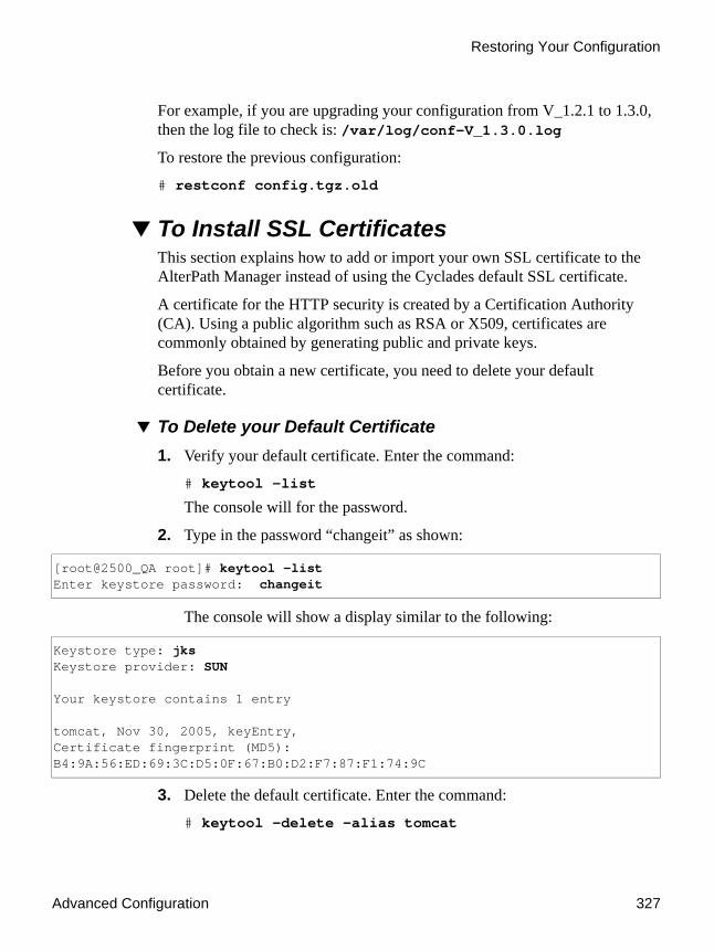
Advanced Configuration 327
Restoring Your Configuration
For example, if you are upgrading your configuration from V_1.2.1 to 1.3.0, then the log file to check is: /var/log/conf-V_1.3.0.log
To restore the previous configuration:
# restconf config.tgz.old
To Install SSL CertificatesThis section explains how to add or import your own SSL certificate to the AlterPath Manager instead of using the Cyclades default SSL certificate.
A certificate for the HTTP security is created by a Certification Authority (CA). Using a public algorithm such as RSA or X509, certificates are commonly obtained by generating public and private keys.
Before you obtain a new certificate, you need to delete your default certificate.
To Delete your Default Certificate1. Verify your default certificate. Enter the command:
# keytool -list
The console will for the password.
2. Type in the password “changeit” as shown:
The console will show a display similar to the following:
3. Delete the default certificate. Enter the command:
# keytool -delete -alias tomcat
[root@2500_QA root]# keytool -listEnter keystore password: changeit
Keystore type: jksKeystore provider: SUN Your keystore contains 1 entry tomcat, Nov 30, 2005, keyEntry,Certificate fingerprint (MD5): B4:9A:56:ED:69:3C:D5:0F:67:B0:D2:F7:87:F1:74:9C

Restoring Your Configuration
328 AlterPath Manager Installation, Configuration, and User’s Guide
The console will prompt you for the password. After you enter the password, the display will appear as follows:
4. Verify that the certificate was deleted. Enter the command:
# keytool -list
After you enter the password, the console terminal will display:
5. Save your configuration. Enter the command:
# saveconf
To Obtain and Install a New SSL Certificate6. Enter OpenSSL command.
On a Linux computer, you can generate a key using the Open SSL package through the command:
# openssl req -new -nodes -keyout private.key -out public.csr
If you use this command, the following information is required:
[root@2500_QA root]# keytool -delete -alias tomcat Enter keystore password: changeit
[root@2500_QA root]# keytool -listEnter keystore password: changeit
Keystore type: jksKeystore provider: SUN
Your keystore contains 0 entries
Table 5-6: Information for the “openssl” Command
Parameter Description
Country Name (2-letter code) [AU]: The 2-letter country code.
State or Province Name (full name)
[Some-State]:
The full name (not the code) of the state.
Locality Name (e.g., city) [ ]: The name of your city.

Advanced Configuration 329
Restoring Your Configuration
You may skip the other requested information.
The command generates a Certificate Signing Request (CSR) which contains some personal (or corporate) information and its public key.
7. Submit the CSR to the CA
Once generated, submit the CSR and some personal data to the CA. You can request this service by selecting from a list of CAs at the following URL:
pki-page.org
The service is not free. Before sending the certificate, the CA will analyze your request for policy approval.
8. Upon receipt, install the certificate
Once the CSR is approved, the CA sends a certificate (e.g., jcertfile.cer) to the origin and stores a copy on a directory server.
If you are satisfied that the certificate is valid, then you can import the certificate to your keystore using the “-import” subcommand:
keytool -import -alias tomcat -file <jcert.cer>
Organization Name (e.g., company)
[Internet Widgits Ltd]:
Organization that you work for or want to obtain the certificate for.
Organizational Unit Name (e.g., section) [ ]:
Department or section where you work.
Common Name (e.g., your name or your server’s hostname) [ ]:
Name of the machine where the certificate must be installed.
Email Address [ ]: Your email address or the administrator’s.
Table 5-6: Information for the “openssl” Command (Continued)
Parameter Description
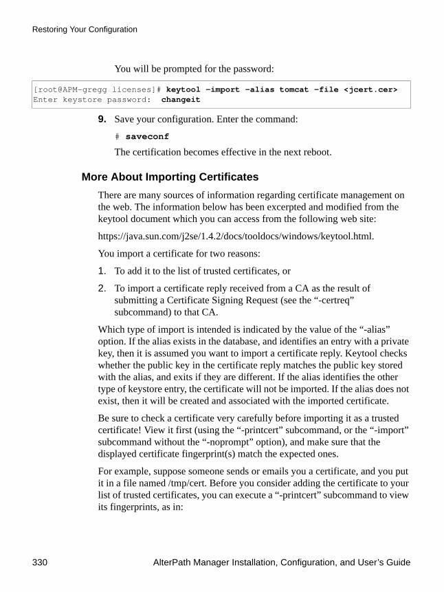
Restoring Your Configuration
330 AlterPath Manager Installation, Configuration, and User’s Guide
You will be prompted for the password:
9. Save your configuration. Enter the command:
# saveconf
The certification becomes effective in the next reboot.
More About Importing CertificatesThere are many sources of information regarding certificate management on the web. The information below has been excerpted and modified from the keytool document which you can access from the following web site:
https://java.sun.com/j2se/1.4.2/docs/tooldocs/windows/keytool.html.
You import a certificate for two reasons:
1. To add it to the list of trusted certificates, or
2. To import a certificate reply received from a CA as the result of submitting a Certificate Signing Request (see the “-certreq” subcommand) to that CA.
Which type of import is intended is indicated by the value of the “-alias” option. If the alias exists in the database, and identifies an entry with a private key, then it is assumed you want to import a certificate reply. Keytool checks whether the public key in the certificate reply matches the public key stored with the alias, and exits if they are different. If the alias identifies the other type of keystore entry, the certificate will not be imported. If the alias does not exist, then it will be created and associated with the imported certificate.
Be sure to check a certificate very carefully before importing it as a trusted certificate! View it first (using the “-printcert” subcommand, or the “-import” subcommand without the “-noprompt” option), and make sure that the displayed certificate fingerprint(s) match the expected ones.
For example, suppose someone sends or emails you a certificate, and you put it in a file named /tmp/cert. Before you consider adding the certificate to your list of trusted certificates, you can execute a “-printcert” subcommand to view its fingerprints, as in:
[root@APM-gregg licenses]# keytool -import -alias tomcat -file <jcert.cer>Enter keystore password: changeit

Advanced Configuration 331
Restoring Your Configuration
# keytool -printcert -file /tmp/certOwner: CN=ll, OU=ll, O=ll, L=ll, S=ll, C=llIssuer: CN=ll, OU=ll, O=ll, L=ll, S=ll, C=llSerial Number: 59092b34Valid from: Thu JUL 01 18:01:13 PDT 2004until: Wed SEP 08 17:01:13 PST 2004Certificate Fingerprints:MD5: 11:81:AD:92:C8:E5:0E:A2:01:2E:D4:7A:D7:5F:07:6FSHA1: 20:B6:17:FA:EF:E5:55:8A:D0:71:1F:E8:D6:9D:C0:37:1
Then call or contact the person who sent the certificate, and compare the fingerprint(s) that you see with the ones that they show. Only if the fingerprints are equal is it guaranteed that the certificate has not been replaced in transit with somebody else’s (for example, an attacker’s) certificate. If such an attack took place, and you did not check the certificate before you imported it, you would end up trusting anything the attacker has signed (for example, a JAR file with malicious class files inside).
Note: It is not required that you execute a “-printcert” subcommand prior to importing a certificate, since before adding a certificate to the list of trusted certificates in the keystore, the “-import” subcommand prints out the certificate information and prompts you to verify it. You then have the option of aborting the import operation. This is only the case if you invoke the “-import” subcommand without the “-noprompt” option. If the “-noprompt” option is given, then there is no interaction with the user.
If you are satisfied that the certificate is valid, then you can add it to your key store as follows:
# keytool -import -alias tomcat -file <jcert.cer>
This creates a trusted certificate entry in the keystore, with the data from the file <jcertfile.cer>, and assigns the alias tomcat to the entry.

Restoring Your Configuration
332 AlterPath Manager Installation, Configuration, and User’s Guide

Hardware Specifications
Feature AlterPath E2000 AlterPath 2500 AlterPath 5000
CPU Intel® Celeron® 850MHz Intel Celeron 3.0GHz 2 x Intel Xeon 3.0GHz
Memory 512MB RAM256MB compact flash
2GB RAM256MB compact flash
4GB RAM512MB compact flash
HDD 80GB SATA 160GB SATA 2 x 160GB SATA RAID 0, 1
Interfaces 2 x 10/100 MB auto sense Ethernet
2 x 10/100/1000 auto sense Ethernet
2 x 10/100/1000 auto sense Ethernet
Dimensions (W x D x H)
1U @ 17 x 14.5 x 1.75 in(43.18 x 36.25 x 4.45 cm)
1U @ 16.8 x 14 x 1.75 in(42.67 x 35.56 x 4.45 cm)
2U @ 16.7 x 25.6 x 3.5 in(42.418 x 65.024 x 8.89 cm)
PCI Slots 2 1 (not currently supported) 3 (not currently supported)
LCD front panel
No Yes Yes
Modem Support
External modem in AUX serial port
Eicon DS series ISDN BRI-2M - International,
Eicon DS series ISDN 4BRI-8M
Equinox SST-MM4P UNIV
Perle V90-modem
Eicon DS series ISDN BRI-2M - international,
Eicon DS series ISDN 4BRI-8M
Equinox SST-MM4P UNIV
Perle V90-modem
Eicon DS series ISDN BRI-2M - international,
Eicon DS series ISDN 4BRI-8M
Equinox SST-MM4P UNIV
Serial Serial console (built-in)Perle multi-port serialCyclades 8Yo serial
Serial console (built- in)Perle multi-port serial
Serial console (built-in)Perle multi-port serial
Ethernet Portwell, Inc. (built-in)
Adlink PCI 8213 4-port LAN
SuperMicro (built-in)
Adlink PCI 8213 4-port LAN
SuperMicro (built-in)
Adlink PCI 8213 4-port LAN
Appendix ATechnical Specifications

334 AlterPath Manager Installation, Configuration, and User’s Guide
Power Consumption vs. Heat Exchange
Power Supply 150W, single, 115 - 230V~, autoranging
260W, single, 115 - 230V~, autoranging
2 x 500W hot swap redundant, 115 - 230V~, autoranging
Operating Temperature
50°F to 112°F (10°C to 44°C)
50°F to 95°F (10°C to 35°C 50°F to 95°F (10°C to 35°C
Operating Humidity
20% to 90% relative, non-condensing
5% to 90% relative, non-condensing
5% to 90% relative, non-condensing
Storage Temperature
32°F to 158°F (0°C to 70°C) -40°F to 158°F(-40°C to 70°C
-40°F to 158°F(-40°C to 70°C
Storage Humidity
5% to 95% relative, non-condensing
5% to 95% relative, non-condensing
5% to 95% relative, non-condensing
Input = 120VAC Input = 23VAC
Model Power (Watts)
Heat Exchange (BTU/hr) Power (Watts)
Heat Exchange (BTU/hr)
APM2500 54 184 58 198
APM5000 288 984 299 1021
Feature AlterPath E2000 AlterPath 2500 AlterPath 5000

Technical Specifications 335
Software Specifications
Feature AlterPath E2000 AlterPath 2500 AlterPath 5000
Operating system
Linux 2.6.x (embedded) Linux 2.6.x (embedded) Linux 2.6.x (embedded)
Users and administrators
Unlimited Unlimited Unlimited
Managed devices
2048 2048 2048
Managed consoles
4096 (fixed) 1024 to 8192 (licensed) 1024 to 32768 (licensed)
Data logging 256 (fixed) 64 to 512 (licensed) 64 to 2048 (licensed
Concurrent serial console sessions
256 (fixed) 64 to 512 (licensed) 64 to 2048 (licensed
Support for KVM/net
Yes (SW 1.1.0 and above) Yes (SW 1.1.0 and above) Yes (SW 1.1.0 and above)
Support for OnSite
Yes Yes Yes
Support for TS Yes Yes Yes
Support for ACS
Yes Yes Yes
AlterPath Integrator for HP OpenView
Yes Yes Yes
Heartbeat/Failover/Data sync
No Yes Yes
Supported web browsers
Internet Explorer 6.0 Mozilla 1.02Netscape 7.x (x > 1)Netscape 8.x
Internet Explorer 6.0 Mozilla 1.02Netscape 7.x (x > 1)Netscape 8.x
Internet Explorer 6.0 Mozilla 1.02Netscape 7.x (x > 1)Netscape 8.x
Java runtime plug-ins
1.4.2 or greater 1.4.2 or greater 1.4.2 or greater

336 AlterPath Manager Installation, Configuration, and User’s Guide

The AlterPath Manager allows you to automatically dial out to remote console servers such as the AlterPath Console Server (ACS) or Terminal Server Series (TS) if the network connection is lost.
In the remote console server, you can connect an external modem to a serial port, or use a PCMCIA modem in the case of the ACS. This section explains the procedure for configuring either modem.
To Configure the PCMCIA Modem1. Edit the file /etc/ppp/pap-secrets.
When the file is opened for the first time, it should look something like this:
2. Add the following line:* * "" *
The file should now look something like this:
This configures the modem to accept any password.
To Configure the External ModemTo configure your external modem, perform the following steps:
Caution: Ensure that you do not configure the console where the modem is attached otherwise any upload process on the console will overwrite your configuration.
# Secrets for authentication using PAP# client server secret IP addresses#"mary" * "marypasswd" *
# Secrets for authentication using PAP# client server secret IP addresses#"mary" * "marypasswd" ** * "" *
Appendix BACS Modem Configuration
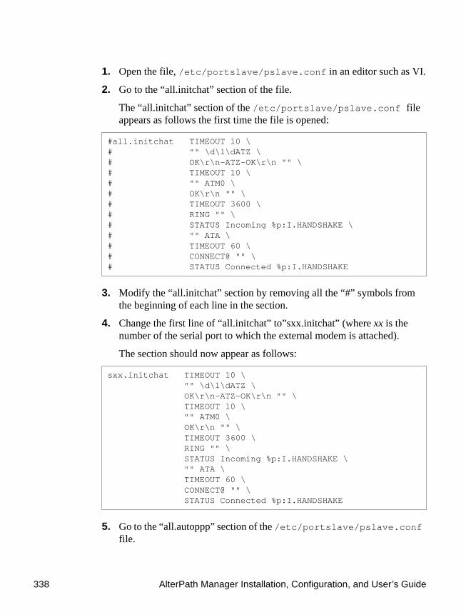
338 AlterPath Manager Installation, Configuration, and User’s Guide
1. Open the file, /etc/portslave/pslave.conf in an editor such as VI.
2. Go to the “all.initchat” section of the file.
The “all.initchat” section of the /etc/portslave/pslave.conf file appears as follows the first time the file is opened:
3. Modify the “all.initchat” section by removing all the “#” symbols from the beginning of each line in the section.
4. Change the first line of “all.initchat” to”sxx.initchat” (where xx is the number of the serial port to which the external modem is attached).
The section should now appear as follows:
5. Go to the “all.autoppp” section of the /etc/portslave/pslave.conf file.
#all.initchat TIMEOUT 10 \# "" \d\l\dATZ \# OK\r\n-ATZ-OK\r\n "" \# TIMEOUT 10 \# "" ATM0 \# OK\r\n "" \# TIMEOUT 3600 \# RING "" \# STATUS Incoming %p:I.HANDSHAKE \# "" ATA \# TIMEOUT 60 \# CONNECT@ "" \# STATUS Connected %p:I.HANDSHAKE
sxx.initchat TIMEOUT 10 \ "" \d\l\dATZ \ OK\r\n-ATZ-OK\r\n "" \ TIMEOUT 10 \ "" ATM0 \ OK\r\n "" \ TIMEOUT 3600 \ RING "" \ STATUS Incoming %p:I.HANDSHAKE \ "" ATA \ TIMEOUT 60 \ CONNECT@ "" \ STATUS Connected %p:I.HANDSHAKE

ACS Modem Configuration 339
The “all.autoppp” section will appear as follows when the file is first opened:
6. Remove the “#” symbols from the beginning of the first 4 lines in this section.
Optionally, you can remove the two remaining lines that begin with “#” (“ms-dns 192.168.160.5 ms-dns 0.0.0.0 \” and “plugin /usr/lib/libpsr.so”).
Note: If you do not remove these two lines, leave the “#” symbol in front of each one.
7. Change “all.autoppp” to “sxx.autoppp” (where xx is the number of the serial port to which the external modem is attached).
8. In the first line of this section, change “%i:%j” to “0.0.0.0:0.0.0.0”.
9. Remove the backslash from end of the line that reads: “mtu %t mru %t \” .
The section should now appear as follows:
10. Go to the “all.pppopt” section of the /etc/portslave/pslave.conf file.
#all.autoppp %i:%j novj \# proxyarp modem asyncmap 000A0000 \# noipx noccp login auth require-pap refuse-chap \# mtu %t mru %t \# ms-dns 192.168.160.5 ms-dns 0.0.0.0 \# plugin /usr/lib/libpsr.so
sxx.autoppp 0.0.0.0:0.0.0.0 novj \ proxyarp modem asyncmap 000A0000 \ noipx noccp login auth require-pap refuse-chap \ mtu %t mru %t# ms-dns 192.168.160.5 ms-dns 0.0.0.0 \# plugin /usr/lib/libpsr.so

340 AlterPath Manager Installation, Configuration, and User’s Guide
The “all.pppopt” section will appear as follows when the file is first opened
11. Remove the “#” symbols from the beginning of the first 4 lines in this section.
Optionally, you can remove the two remaining lines that begin with “#” (“ms-dns 192.168.160.5 ms-dns 0.0.0.0 \” and “plugin /usr/lib/libpsr.so”).
Note: If you do not remove these two lines, leave the “#” symbol in front of each one.
12. Change “all.pppopt” to “sxx.pppopt” (where xx is the number of the serial port to which the external modem is attached).
13. In the first line of this section, change "%i:%j" to "0.0.0.0:0.0.0.0".
14. Remove the backslash from the end of the line that reads:“idle %I maxconnect %T \”.
The section should now appear as follows:
15. Edit the file “/etc/ppp/pap-secrets”.
#all.pppopt %i:%j novj \# proxyarp modem asyncmap 000A0000 \# noipx noccp mtu %t mru %t netmask %m \# idle %I maxconnect %T \# ms-dns 192.168.160.5 ms-dns 0.0.0.0 \# plugin /usr/lib/libpsr.so
sxx.pppopt 0.0.0.0:0.0.0.0 novj \ proxyarp modem asyncmap 000A0000 \ noipx noccp mtu %t mru %t netmask %m \ idle %I maxconnect %T # ms-dns 192.168.160.5 ms-dns 0.0.0.0 \# plugin /usr/lib/libpsr.so

ACS Modem Configuration 341
When the file is opened for the first time, it should look something like this:
16. Add the following line:* * "" *
The file should now look something like this:
This configures the modem to accept any password.
17. Ensure that the filename “/etc/ppp/ pap-secrets” is listed in “/etc/config_files”. If not, edit “/etc/config_files” and add the following line to the end of the file. /etc/ppp/pap-secrets
18. If for any reason you are enabling syslog-ng on the ACS or TS, it is not advisable to use “root” as the Admin Username for this device. Instead, create a user in the ACS or TS whose name will be the APM Admin Username for that device.
19. After creating the user in the ACS or TS, give it root privileges by editing /etc/passwd for the user by changing the UID and GID fields to 0.
A sample user with the fields changed to 0 is as follows:
20. Change the ownership of the user’s home directory to root as follows:
# chown root /home/edson
21. Edit the file “/etc/ssh/sshd_config” to remove the comment symbol (#) in front of the line:
AuthorizedKeysFile /etc/ssh/authorized_keys
# Secrets for authentication using PAP# client server secret IP addresses#"mary" * "marypasswd" *
# Secrets for authentication using PAP# client server secret IP addresses#"mary" * "marypasswd" ** * "" *
edson:fTEQb6zEnuIEQ:0:0:Embedix User...:/home/edson:/bin/sh

342 AlterPath Manager Installation, Configuration, and User’s Guide

Data Logging Session ActivationThe AlterPath Manager E2000 is available with a fixed capability of 256 activated Data Logging Sessions (DLSs). This is also equal to the maximum number of concurrent console connections. The maximum number of managed consoles, or the total number of configurable console connections for the APM E2000 is 4096.
The APM 2500 and APM 5000 come with a standard base capacity of 64 activated DLSs and a capacity of 1024 managed consoles.
Caution: Licenses (except for factory default licenses) must be reinstalled after you recreate the system partition or after you run the “installimg” command.
If you want to preserve your licenses before you recreate a system partition or before you run “installimg,” you can edit the file “/etc/files.list” and add your license file name to the list of files. Be sure to use the full path of each license file name you enter into this file. For example if the name of the license file you are adding is “APM_FA_DLS_64_128.enc” you should enter the full path name:/var/apm/licenses/data/APM_FA_DLS_64_128.encBe sure to follow up with the “saveconf” command. It is also a good idea to save a copy of each license file on a server that can be accessed by your APM, just to be extra safe.
If at any time you run “defconf” the file, “/etc/files.list” will revert back to its original state, and you will need to reinstall your license.
Additional DLS at Time of PurchaseAdditional DLS activation can be included at the time of initial purchase, or it can be added as a feature activation conversion. Cyclades recommends you purchase the additional DLS activation with your APM. There is a price benefit when you buy the DLS activation this way.
Appendix CDLS Activation

Data Logging Session Activation
344 AlterPath Manager Installation, Configuration, and User’s Guide
Initial purchase part numbers for the DLS activation options along with their corresponding managed console capacities are shown in the table that follows:
DLS Activation ConversionFor the APM 2500 and 5000, DLS capacity can be expanded and additional capacity can be purchased from Cyclades. This is an activation conversion. Activation conversion options are shown in the following table:
Table C-1: DLS Activations Available at Initial Purchase
Part Number DLSsMax. Number of Managed Consoles
APM 2500
APM 2500 Base System 64 1024
APM B-DLS 128 128 2048
APM B-DLS 256 256 4096
APM B-DLS 512 512 8192
APM 5000
APM 5000 Base System 64 1024
APM B-DLS 128 128 2048
APM B-DLS 256 256 4096
APM B-DLS 512 512 8192
APM B-DLS 1024 1024 16384
APM B-DLS 1536 1536 24576
APM B-DLS 2048 2048 32768

DLS Activation 345
Data Logging Session Activation
Table C-2: Activation Conversion Options
Conversion Number From To
AlterPath 2500
APM FA-DLS 64-128 64 128
APM FA-DLS 64-256 64 256
APM FA-DLS 64-512 64 512
APM FA-DLS 128-256 128 256
APM FA-DLS 128-512 128 512
APM FA-DLS 256-512 256 512
AlterPath 5000
APM FA-DLS 64-128 64 128
APM FA-DLS 64-256 64 256
APM FA-DLS 64-512 64 512
APM FA-DLS 64-1024 64 1024
APM FA-DLS 64-1536 64 1536
APM FA-DLS 64-2048 64 2048
APM FA-DLS 128-256 128 256
APM FA-DLS 128-512 128 512
APM FA-DLS 128-1024 128 1024
APM FA-DLS 128-1536 128 1536
APM FA-DLS 128-2048 128 2048
APM FA-DLS 256-512 256 512
APM FA-DLS 256-1024 256 1024
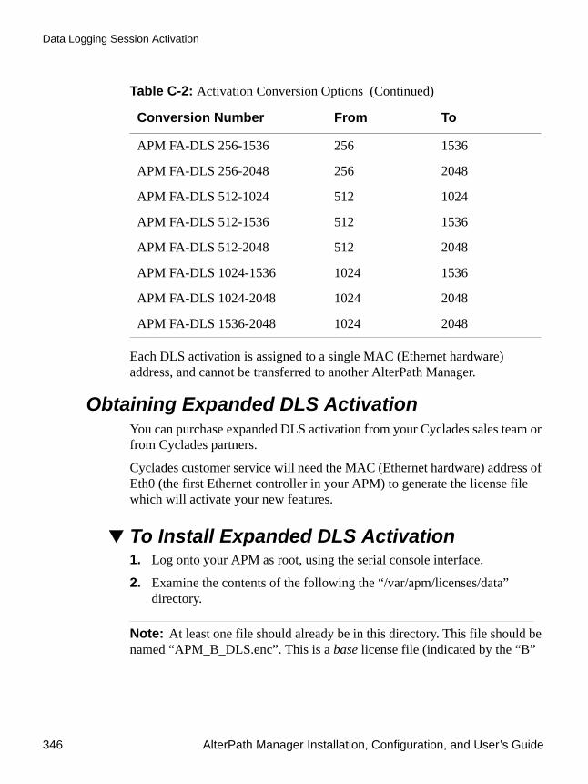
Data Logging Session Activation
346 AlterPath Manager Installation, Configuration, and User’s Guide
Each DLS activation is assigned to a single MAC (Ethernet hardware) address, and cannot be transferred to another AlterPath Manager.
Obtaining Expanded DLS ActivationYou can purchase expanded DLS activation from your Cyclades sales team or from Cyclades partners.
Cyclades customer service will need the MAC (Ethernet hardware) address of Eth0 (the first Ethernet controller in your APM) to generate the license file which will activate your new features.
To Install Expanded DLS Activation1. Log onto your APM as root, using the serial console interface.
2. Examine the contents of the following the “/var/apm/licenses/data” directory.
Note: At least one file should already be in this directory. This file should be named “APM_B_DLS.enc”. This is a base license file (indicated by the “B”
APM FA-DLS 256-1536 256 1536
APM FA-DLS 256-2048 256 2048
APM FA-DLS 512-1024 512 1024
APM FA-DLS 512-1536 512 1536
APM FA-DLS 512-2048 512 2048
APM FA-DLS 1024-1536 1024 1536
APM FA-DLS 1024-2048 1024 2048
APM FA-DLS 1536-2048 1024 2048
Table C-2: Activation Conversion Options (Continued)
Conversion Number From To

DLS Activation 347
Data Logging Session Activation
in the file name). Only one base file is allowed in the “/var/apm/licenses/data” directory.
3. Copy any new license files into this directory.
Note: If you have more than one feature activation (FA) license file for DLS activation, you must be sure all the license files are included in the “/var/apm/licenses/data” directory.
For example, if you purchase a license to expand from 128 to 512 DLSs, you directory will contain the following files prior to the new expansion:
APM_B_DLS_64.enc APM_FA_DLS_64_128.enc
When you copy your new license file into the “/var/apm/licenses/data” directory, it must contain all of the following:
APM_B_DLS_64.enc APM_FA_DLS_64_128.encAPM_FA_DLS_128_256.enc
Note: Multiple FA (feature activation) license files must be named with sequential number ranges, as shown in the foregoing example.
4. Enable your license immediately, by entering the command:
# /etc/init.d/tomcat restart
Verifying Your Current DLS ActivationLog on to the Web User Interface and click on the “About” link in the upper left corner of the display. A window similar to the following will appear:

Data Logging Session Activation
348 AlterPath Manager Installation, Configuration, and User’s Guide
Figure C-1: Feature Window (full content scrolled)
You can also verify your current DLS Activation by logging onto your APM CLI as root and running the following command:
# ls /var/apm/licenses/data
If DLS is activated, the screen will display a file name similar to this:
APM_B_DLS_256.enc
The foregoing file name indicates a DLS capacity of 256 logging sessions.
Verifying your MAC addressesLog on to the CLI (on the serial console port) as root or as admin and run the following command:
# ifconfig

DLS Activation 349
Data Logging Session Activation
A display similar to the following will appear:
The numbers following the “HWaddr” subheading for each Ethernet controller installed (eth0 and eth1 by default) is the MAC address for the controller.
eth0 Link encap:Ethernet HWaddr 00:90:FB:81:57:17 inet addr:192.168.48.162 Bcast:192.168.51.255 Mask:255.255.252.0 UP BROADCAST RUNNING MULTICAST MTU:1500 Metric:1 RX packets:9691587 errors:133 dropped:0 overruns:0 frame:133 TX packets:5726282 errors:0 dropped:0 overruns:0 carrier:0 collisions:1038728 txqueuelen:1000 RX bytes:685270715 (653.5 Mb) TX bytes:548308906 (522.9 Mb) Interrupt:10 Base address:0xc000 Memory:e5020000-e5020038
eth1 Link encap:Ethernet HWaddr 00:90:FB:01:8C:D7 inet addr:10.10.10.2 Bcast:10.10.255.255 Mask:255.255.0.0 UP BROADCAST RUNNING MULTICAST MTU:1500 Metric:1 RX packets:632 errors:0 dropped:0 overruns:0 frame:0 TX packets:622 errors:0 dropped:0 overruns:0 carrier:0 collisions:0 txqueuelen:1000 RX bytes:38288 (37.3 Kb) TX bytes:42288 (41.2 Kb) Interrupt:11 Base address:0xc400 Memory:e5021000-e5021038
lo Link encap:Local Loopback inet addr:127.0.0.1 Mask:255.0.0.0 UP LOOPBACK RUNNING MTU:16436 Metric:1 RX packets:113528 errors:0 dropped:0 overruns:0 frame:0 TX packets:113528 errors:0 dropped:0 overruns:0 carrier:0 collisions:0 txqueuelen:0 RX bytes:15268713 (14.5 Mb) TX bytes:15268713 (14.5 Mb)

Data Logging Session Activation
350 AlterPath Manager Installation, Configuration, and User’s Guide

Appendix DSafety Information
Follow the precautions in this appendix when installing Cyclades products. Failure to observe the listed precautions may result in personal injury or damage to equipment. Failing to observe compliance requirements makes the equipment no longer compliant. See “Safety Considerations When Rack Mounting” on page 28, and “Technical Specifications” on page 333for specific standards and compliance information for the AlterPath Manager.
General Safety PrecautionsObserve the following general precautions when setting up and using Cyclades equipment.
• Follow all cautions and instructions marked on the equipment.• Follow all cautions and instructions in the installation documentation or
on any cautionary cards shipped with the product.• Do not push objects through the openings in the equipment. Dangerous
voltages may be present. Objects with conductive properties can cause fire, electric shock, or damage to the equipment.
• Do not make mechanical or electrical modifications to the equipment.• Do not block or cover openings on the equipment.• Chose a location that avoids excessive heat, direct sunlight, dust, or
chemical exposure, all of which can cause the product to fail. For example, do not place a Cyclades product near a radiator or heat register. which can cause overheating.
• Connect products that have dual power supplies to two separate power sources, for example, one commercial circuit and one uninterruptible

Rack or Cabinet Placement
352 AlterPath Manager Installation, Configuration, and User’s Guide
power supply (UPS). The power sources must be independent of each other and must be controlled by a separate circuit breaker.
• For products that have AC power supplies, ensure that the voltage and frequency of the power source match the voltage and frequency on the label on the equipment.
• Products with AC power supplies have grounding-type three-wire power cords. Make sure the power cords are plugged into single-phase power systems that have a neutral ground.
• Do not use household extension power cords with Cyclades equipment because extension cords are not designed for use with computer systems and do not have overload protection.
• Make sure to connect DC power supplies to a grounded return. • Ensure that air flow is sufficient to prevent extreme operating
temperatures. Provide a minimum space of 6 inches (15 cm) in front and back for adequate airflow.
• Keep power and interface cables clear of foot traffic. Route cables inside walls, under the floor, through the ceiling, or in protective channels or raceways.
• Route interface cables away from motors and other sources of magnetic or radio frequency interference.
• Stay within specified cable length limitations.• Leave enough space in front and back of the equipment to allow access
for servicing.
Rack or Cabinet Placement When installing Cyclades equipment in a rack or cabinet, observe the following precautions:
• Ensure that the floor’s surface is level.• Load equipment starting at the bottom first and filling the rack or cabinet
from the bottom to the top.• Exercise caution to ensure that the rack or cabinet does not tip during
installation and use an anti-tilt bar.

Safety Information 353
Table Placement
Table Placement• Choose a desk or table sturdy enough to hold the equipment.• Place the equipment so that at least 50% of the equipment is inside the
table or desk’s leg support area to avoid tipping of the table or desk.

Table Placement
354 AlterPath Manager Installation, Configuration, and User’s Guide

3DESTriple Data Encryption Standard, an encrypting algorithm (cipher) that encrypts data three times, using a unique key each time, to prevent unauthorized viewers from viewing or changing it. 3DES encryption is one of the security features provided by Cyclades products to support data center security policies.
authenticationControlling access by requiring users to enter names and passwords. Anyone accessing Cyclades products and connected devices must log in by entering a username and password. The usernames and passwords entered during login attempts are checked against a database that lists all the valid usernames along with the encrypted passwords. Access is denied if the username or password is not valid. The password database being checked can reside either locally (on the device being accessed) or on an authentication server on the network. If an authentication method is selected that relies on a server, the corresponding authentication server must be already installed and configured in order for authentication to work. Using one or more of the many types of popular authentication methods can reduce administrator workload when an administrator needs to add, modify, of delete user accounts.
ALOM (Advanced Lights Out Manager)Remote out-of-band management technology on certain Sun servers that includes an independent system controller (service processor) and firmware. Provides remote monitoring, logging, alerting, and basic control of the server in a “lights out” environment.
ASICApplication-Specific Integrated Circuit. Pronounced “ay-sik.” A type of chip used for applications that provide a specific function, such as an ASIC chips that serves as a BMC.
Glossary

356 AlterPath Manager Installation, Configuration, and User’s Guide
Baseboard Management Controller (BMC)On some servers, an internal processor separate from the main system that operates even if the main processor is not operable, sits on the server’s motherboard or on the chassis of a blade server. Monitors on-board instrumentation. Provides remote reset or power-cycle capabilities. Enables remote access to BIOS configuration or operating system console information, and in some cases provides KVM control of the server. Includes a communication protocol that brings the information and control to administrators.
BIOS (basic input/output systemPronounced “bye-ose.” Instructions in the onboard flash memory that start up (boot) a computer without the need to access programs from a disk. Sometimes used for the name of the memory chip where the start-up instructions reside. BIOS access is available even during disk failures. Administrators often need to access the BIOS while troubleshooting, for example to temporarily change the location from which the system boots. How to access the BIOS varies from one manufacturer to the other.
baud ratePronounced “bawd rate.” When configuring terminal or modem settings on serial ports and console port connections on AlterPath devices, the specified baud rate must match the baud rate of the connected devices.
Options range from 2400–921600 Kbps. 9600 is the most-common baud rate for devices.
CAT5
An Ethernet cable standard defined by the Electronic Industries Association and Telecommunications Industry Association (commonly known as EIA/TIA). CAT5 is the fifth generation of twisted pair Ethernet cabling and the most popular of all twisted pair cables in use today. The support for CAT5 cabling in many Cyclades products allows the use of existing cabling infrastructure in the data center.
CLI
A means of operating a computer by typing a text command at an on-screen prompt and hitting the Enter or Return key to issue the

Advanced Configuration 357
command. The computer then processes the command, displays whatever output is appropriate, and presents another prompt for the next command. Typical commands are to run a program, enter a text editor, list files, and change directories. This mode of interaction is common, for instance, in the traditional DOS and UNIX operating systems. Command line interface. An interface that allows users to use text commands that tell computers to perform actions (compared to using a GUI). Through a CLI, individual commands can be given to the computer one at a time using a keyboard. Alternately, users can save a series of frequently-used commands in a file called a script. Being able to create and run scripts to automate repetitive tasks is one of the reasons many administrators prefer using a CLI.
Most computer operating systems have both GUI and CLI modes. Cyclades products run the Linux operating system, and most Cyclades products provide CLI access. CLI access is achieved through several different means. For one example, if a remote administrator uses Telnet to access an AlterPath OnSite, the administrator can then tell the OnSite to perform actions using the CLI by typing commands on the Linux shell's command line.
Do not be confused by the fact that some Cyclades products offer a management tool called the CLI, which has the same name as the term used in general for any command line interface. The Admin user can select “CLI” at a prompt after logging into the APM console (a regular user logging into the APM console gets the “CLI” prompt by default). The Cyclades CLI tool provides many commands and nested parameters in a format called the CLI parameter tree.
Client-side management software—See Management software
ConsoleThis term is used to mean the serial console interface that is present on most Cyclades devices. It is a physical serial port that interfaces with a serial terminal that can be used to interface with the device. The serial console interface allows an administrator to have shell access to the device. The administrator can use this interface for advanced configurations.
On the AlterPath Manager, “Console” also is used to describe any of the ports on a device, such as KVM ports on a KVM/net device or an OnSite device; or any of the serial ports on an ACS device, a TS device, or an OnSite device.

358 AlterPath Manager Installation, Configuration, and User’s Guide
ChecksumAn algorithm, usually generated by a program, to check the integrity of a target file or target packet of data that has been transferred across a network. A very common checksum program is “md5sum” that is run after a target file has been downloaded. The checksum file generated by “md5sum” is compared with a checksum file that was generated on the original target file and stored with it prior to the target file’s transmission. If the two checksum files match, it is nearly a certainty that the target file was transferred correctly.
ConsolidationProvides controlled access to basic management features on multiple Ethernet-based servers that have embedded service processors, using only one Internet address. When managed separately, each service processor needs its own IP address. Managing multiple servers with multiple IP address is both expensive and time consuming without consolidation.
DecryptionDecoding of data that has been encrypted using an encryption method.
DeviceFrom the AlterPath Manager’s point of view, a device is a product that the APM is designed to control directly through an Ethernet port. This includes the KVM/net, ACS, TS, and the OnSite. Any of the individual ports on one of these devices, which is designed to connect to a server or workstation, is a console.
Encryption
Translation of data into a secret format using a series of mathematical functions so that only the recipient can decode it. Designed to protect unauthorized viewing or modification of data, even when the encrypted data is travelling over unsecure media (such as the Internet). See 3DES and SSH. As an example, a remote terminal session using secure shell SSH usually encrypts data using 3DES or better algorithms.
DRAC (Dell Remote Assistant Cards)Dell’s solution
Advanced Configuration 359
GUIGraphical user interface (pronounced GOO-ee). A computer interface that allows users to tell computers to perform actions by clicking on graphical elements such as icons, choosing options from menus, and typing in text fields on forms displayed on the computer screen. Many Cyclades products provide GUI access through the Web Manager.
iLO (Integrated Lights Out)HP’s proprietary service processor. Even though HP is a major supporter of IPMI, HP also provides iLO because it provides many more functions than IPMI. The iLO processor resides on the motherboard. As long as power is available to the server, even if the server is off, iLO is active. When the dedicated Ethernet port is plugged into the network, iLO uses DHCP. iLO has a web interface and a telnet interface. When the server is off, only the web interface works.
IPDUIntelligent power distribution unit. Cyclades supports a family of AlterPath PM IPDUs.
IPMI (Intelligent Platform Management Interface)An open standards service processor currently adopted by every major server platform vendor. Its main benefit over other service processors is that it is installed on servers from many vendors, providing one interface and protocol for all servers. Its main disadvantage is that it does not always provide as much functionality as the proprietary service processors.
KerberosNetwork authentication protocol designed to provide strong authentication for client/server applications by using secret-key cryptography.
KVM switchEnables use of only one keyboard, video monitor, and mouse to run multiple servers. Reduces expenses by eliminating the cost of acquiring, powering, cabling, cooling, managing, and finding data-center space for one keyboard, monitor, and mouse for every server. Servers are connected to KVM ports on Cyclades AlterPath KVM switches using AlterPath KVM terminators on the

360 AlterPath Manager Installation, Configuration, and User’s Guide
server end and up to 500 feet of CAT5 cable. AlterPath KVM switches provide authentication and other security features and allow only authorized users to access a restricted set of connected servers. See also KVM analog switch and KVM Over IP switch.
KVM analog switchA KVM switch that requires a local user connection to gain access to the servers that are connected to the switch.
KVM over IPSupports remote access over a LAN or WAN or telephone line using the TCP/IP protocols and a web browser. Enables operations over long distances. Cyclades AlterPath KVM/IP switches are one component of the out-of-band infrastructure,
LDAPLightweight Directory Access Protocol. A set of open protocols for accessing directories of information.
Management console—See service processor
Management softwareEach server company that offers a service processor produces its own client side software to access the servers’ management features through the service processor. In some cases, management software is imbedded in the service processor and is presented either as a web interface or as a command line interface accessed using SSH or Telnet, or as both a web interface and command line interface. In other cases, the management software is installed in a client workstation and accesses the management features of the service processor using an IP-based protocol, such as IPMI. Each type of software only manages one server, does not scale, does not address the need for consolidated access-control, multi-user access, data logging, and event detection, encryption and other needs. The <ProductName> (Change variable definition) addresses these needs and provides a single interface to access basic features of multiple-vendors’ service processors.

Advanced Configuration 361
NEBS (Network Equipment Building Systems) ComplianceMeans that equipment has been tested and proven to meet the NEBS requirements commonly adhered to by several telecommunications carriers. The requirements are in place to ensure that telecommunications equipment poses no risk or safety hazard to people, nearby equipment, or to the physical location where the equipment operates, and that equipment is reliable and dependable during both normal and abnormal conditions. Tests address heat release, surface temperature, fire resistance, electromagnetic capability, electrical safety, and manufacturing component characteristics, among other attributes.
NIS (Network Information Service)An industry-standard directory protocol used for authentication, specifically in Sun “legacy” systems.
OOBI (Out-of-band Infrastructure)Provides secure, alternate paths to connect to and manage IP production infrastructure remotely. Components include console servers, KVM switches, IPDUs, and service processor managers. Enables lights out data centers where computers can be monitored, preventively maintained, and restored to operation without site visits by technicians.
Out of bandA type of access to assets that is either separate from or independent of the normal production network. Used for remote monitoring and control even when the managed assets lose connection to the production network. Typically out-of-band access is through an RS-233 or Ethernet console, a power/reset circuit, or a KVM port.
RSC (Remote System Control)Sun’s remote out-of-band management technology on certain Sun servers that includes an independent RSC card and software. Enables the remote administrator to run diagnostic tests, view diagnostic and error messages, reboot the server, and display environmental status information from a remote console even if the server’s operating system goes offline. The RSC firmware runs independently of the host server, and uses standby power drawn from it. The RSC card on some servers include a battery

362 AlterPath Manager Installation, Configuration, and User’s Guide
that provides approximately 30 minutes of power to RSC in case of a power failure.
RSA (Remote Supervisor Adapter)IBM’s
Security
Service processorEthernet-based management console on a server, which provides out of band management through an interface between the server’s administrator and an internal BMC that enables the management features. Management features include serial console emulation (using telnet or IPMI), KVM over IP, power control, sensor and log information from the server hardware, and virtual media. Examples of vendors and the service processor technologies they support are shown in the following table.
ShellA command interpreter on UNIX-based operating systems (like the Linux operating system that controls most Cyclades products). At the time this is being written, Microsoft has announced an upcoming release of a Microsoft shell. A shell typically is accessed in a terminal window where the shell presents a prompt. For example: [admin@OnSite /home/admin]# is the prompt that appears when a user logs into an OnSite as admin and is in the /home/admin directory. Users tell the operating system to perform actions by
Table G-1: Service Processor Technology by Vendor
Vendor Protocol
HP iLO (Integrated Lights Out), Riloe, PCMCIA
Sun RSC (Remote System Control), ALOM
Dell DRAC, PCMCIA
Intel PCMCIA
IBM RSA Remote Supervisor Adapter, Blade Center

Advanced Configuration 363
typing commands in the shell, which interprets the commands and performs the specified actions.
Web ManagerCyclades' web management interface (WMI), which runs in supported browsers.

364 AlterPath Manager Installation, Configuration, and User’s Guide
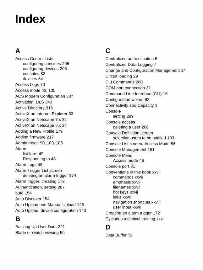
AAccess Control Lists
configuring consoles 205configuring devices 206consoles 82devices 84
Access Logs 70Access mode 43, 105ACS Modem Configuration 337Activation, DLS 343Active Directory 316ActiveX on Internet Explorer 33ActiveX on Netscape 7.x 34ActiveX on Netscape 8.x 34Adding a New Profile 179Adding firmware 217Admin mode 90, 103, 105Alarm
list form 49Responding to 48
Alarm Logs 48Alarm Trigger List screen
deleting an alarm trigger 174Alarm trigger, creating 172Authentication, setting 287auto 154Auto Discover 154Auto Upload and Manual Upload 143Auto Upload, device configuration 143
BBacking Up User Data 221Blade or switch viewing 59
CCentralized authentication 6Centralized Data Logging 7Change and Configuration Management 14Circuit loading 29CLI Commands 280COM port connection 31Command Line Interface (CLI) 16Configuration wizard 92Connectivity and Capacity 1Console
setting 289Console access
deleting a user 208Console Definition screen
selecting users to be notified 193Console List screen, Access Mode 56Console Management 181Console Menu
Access mode 46Console port 31Conventions in this book xxvii
commands xxviiemphasis xxviifilenames xxviihot keys xxviilinks xxviinavigation shortcuts xxviiiuser input xxvii
Creating an alarm trigger 172Cyclades technical training xxxi
DData Buffer 72
Index

366 AlterPath Manager Installation, Configuration, and User’s Guide
Data Logging Session 343Data Synchronization 261Database Configuration 326Date 290, 295
set 290date 295Date and time setting 290, 295Deleting a Device 160Deleting an alarm trigger 174Deleting firmware 217Deploying the APM 18device 154Device Discovery 154Device management
Deleting a device 160Uploading device configuration 143
DHCP 302Dial Up and Dial Back 127, 307Discovery 154DLS 343
Activation conversion 344Additional capacity 343
DLS activation 343Domain name 292Dynamic host configuration protocol 302
EEmail server 295Enable telnet 297Ethernet Bonding 300Ethernet Port Configuration 290Ethernet subinterfaces 293Event Logs 71Examine the Serial Port Parameters 295External Modem, ACS 337
FFailover 261
Fault tolerance 261Firmware Detail screen 218Firmware List screen 215
deleting or adding 217Firmware Management 215, 319Firmware screen 112Firmware upgrades xxxiFirst Time Configuration 90First Time Configuration Wizard 92
HHeartbeat 261Host name 292Hot keys xxviii
Console session 285HP OpenView
NNM 303HyperTerminal 30
IInfo Reporting Main screen 223IP Addresses 30IPDU 256IPMI Sensors 67ISDN 130, 310ISDN Configuration 310
KKermit 30Key features 3
Centralized authentication 6Centralized data logging 7Change and configuration management
14CLI 16Log file compression and rotation 8Prioritized triggers & alarms 8Single point security gateway 5
KVM/net Plus 63, 189, 191

Index 367
KVM/net Plus web control page 63KVM/net Support 18
LLog File Compression and Rotation 8Log rotation 197Logs 68
Access 70Data buffer 72Event 71
Logs, Access Mode 69
MManual Upload, device configuration 143Mechanical loading 29Minicom 30Modifying a Profile 181Multiple Auto Discover 157
NName server 292Navigation shortcuts xxviiiNetwork boot 288Network diagram 27
private 27single 28
NIC cardpre-installation 30
Notifyselecting users to be notified 193
NTP server 295
OOne Time Password 133Online Help 48
relocating 106OnSite Support 19Open LDAP 317Operating temperature 28
Operational Modes 90OTP 133
PPCMCIA Modem, ACS 337Power Management 73, 256Pre-configuration 30Pre-installation 30
IP Addresses 30NIC card 30
Prioritized Triggers & Alarms 8Private Network Diagram 27Private Network Topology 26Product Installation Checklist 21Profile Definition screen
adding a new profile 179modifying a profile 181
Profile List screen 178
RRack mounting
Safety considerations 28RDP 61, 189, 191, 192Recovery, system 222, 323Redundancy 261Reliable earthing, Rack mounting 29Restoring database configuration 326
SSafety Information 351Screen features, general 46Screens
Console List, Access Mode 56Event Logs 71firmware 112Firmware List 215Info Reporting 223Profile List 178User List 200User Profile, Access Mode 77

368 AlterPath Manager Installation, Configuration, and User’s Guide
Set Commands 286setauth 287setboot 288setcons 289setdatetime 290setethernet 290setnames 292setnetwork 293setntp 295setserial 295setsmtp 295Single Network Diagram 28Single Network Topology 26Single point security gateway 5Sudo Support 299Support, technical xxxiiSwitch or blade viewing 59System recovery 222, 323
TTechnical Specifications 333
Technical support xxxiiTechnical training xxxiTelnet 297
enable 297Ticket 53Time 290, 295
set 290Time and date setting 290, 295Time zone 290Training xxxiTypographic Conventions xxvii
UUpgrading firmware xxxiUser Interface, overview 43User List screen 200User Management 199User Profile, Access Mode 77
WWeb Browser Requirements 32Wizard, configuration 92