alternative tunnel - tunneltalk.com
TRANSCRIPT
New system or method of tunnel ventilation
A.R. Ghavami & Co-operates (N.S.C.E. CO.)
August 2016, Seattle WA

Suggested New System or Method for Tunnel Air Ventilation
BACKGROUND OF THE INVENTION
For the past few decades, the important subject of the tunnel air
ventilation (for elimination or minimizing the internal pollutions) has
been mostly done by similar conventional methods. That is, the
current standards of operation have remained the same and intact.
This made the illusion that there were no other ways to solve this
problem. The basis of the named method is (and has been) using the
ceiling type jet fans, using precise calculations, for capacities and
power, which are calculated and selected in accordance to
numerous different factors.
Introduction
1

Current and old tunnel ventilation system using jet
fans installed in the ceiling
Fig.1
2
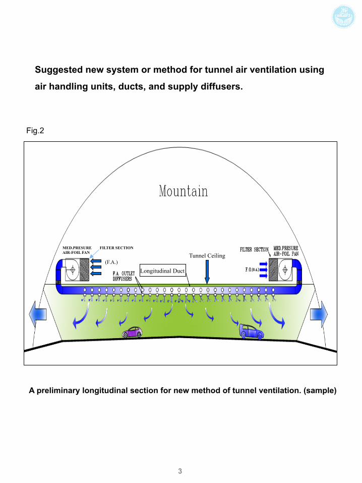
Suggested new system or method for tunnel air ventilation using
air handling units, ducts, and supply diffusers.
Fig.2
MED.PRESURE FILTER SECTION AIR-FOIL FAN
A preliminary longitudinal section for new method of tunnel ventilation. (sample)
3
(F.A.) Tunnel Ceiling
Longitudinal Duct
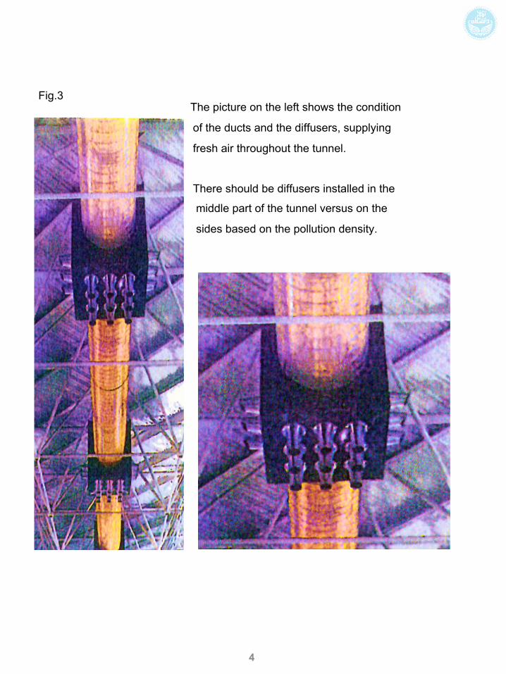
The picture on the left shows the condition
of the ducts and the diffusers, supplying
fresh air throughout the tunnel.
There should be diffusers installed in the
middle part of the tunnel versus on the
sides based on the pollution density.
The image cannot be displayed. Your computer may not have enough memory to open the image, or the image may have been corrupted. Restart your computer, and then open the file again. If the red x still appears, you may have to delete the image and then insert it again.
The image cannot be displayed. Your computer may not have enough memory to open the image, or the image may have been corrupted. Restart your computer, and then open the file again. If the red x still appears, you may have to delete the image and then insert it again.
Fig.3
4

These procedures are normally done and repeated for most of the
tunnels, and final result would be selection of a chain of jet-fans
placed in the ceiling of the tunnel, in one or two longitudinal axis
having certain distances from one another, which draws in the fresh
air from one mouth of the tunnel, to the next mouth of it. This is a
constant and continuous procedure. This chain of operation is done
along the total length of the tunnel and moves the contaminants out
of it.
Following are some brief descriptions of disadvantages, weak
points, and operational difficulties of Jet-Fan Systems/ the
conventional system in use today:
1- Financial needs of the system for heavy investment.
2- Substantial weight of the ceiling type jet fans, especially for
double, triple or more fans, and the cost of special steel hangers.
Most importantly, since jet fans operate in chain formation, there
are constantly and heavily working and depending on one another.
Considering this fact, if one or two units in the chain are inoperable,
it will create an operational gap within the system. Additionally, it
has a negative effect on the safe and correct chain operation.
5

4- The Jet-Fan fan system needs a huge amount of cabling, and
huge consumption of power, for both normal and backup supplies.
The automatic system for the chain has also a complicated wiring
network.
5- The system needs to maintain the electrical consumption for the
units, which relates to the average consumption of each unit. The
total consumption is substantial and the chain needs a high voltage
transfer station for itself and its network. Therefore, the running cost
of energy consumptions during the years of usage will accumulate
to a very large number for the users.
6- Different tunnels are in need of different spare parts, that need
substantial budget for different kinds and models, upkeep of units,
storage, and operation.
7- Need for clear and precise warranties and specifications and
manufacturer guarantees of part’s operational integrity. More so,
there is a need for higher level of technical skilled labors, which
translates into higher wages and thus, bigger annual budgets.
8- A higher level of noise pollution within the tunnel and higher
reflectance of sound during operation of the jet-fans (all
encompassing).
6

9- There are limitations within the unit’s inspection, maintenance,
set-up, and repair of different pieces that may cause temporary
shutdown to the tunnel and traffic built-up, which is very costly to
public and economy, or sometimes impractical to stop the traffic at
all, making the repairs within tunnel impossible or very dangerous
for the crew.
10- Since the ceiling fans are hanging from a cement and stone
foundations, and they may become loose after a while, due to
earth movements or vibration of the fans, there are hidden and
probable danger factors from the weight and the vibration of the
units (to fall on a vehicle, causing major damages/accidents or
death to passengers).
The effect above can be even higher, if the frequency of
rotation of all the fans matches the resonant frequency of a
principal length or portion or component of the tunnel, which can
be an unstable system, with vibrations, with growing amplitude, or
with an increase of the amplitude very quickly. This will cause the
whole system collapses, making it very dangerous for people and
cars in the tunnel at that time.
7

11- There are considerable cost and change of designs, plus
additional problems, if the design and construction of the chain fan
system in some cases are incorrect, to re-do the whole system
from scratch again.
12- Special consideration should be given to the pollutant in some
countries mixed with the bits of desert sand. The Jet-Fan system
has no filtration capabilities, causing the sand to fly like a bullet
from the fan blade, with high speed, which can damage the cars
seriously and can kill the people upon impact. In addition,
designing filters for tunnel air ventilation system is not an easy
task. The chain system will not purify the pollutant found in the air
and acts as a vacuum.
However, the invention and embodiments described
here, below, solve all these problems, and they have not been
addressed or presented, in any prior art.
8

SUMMARY OF THE INVENTION
In one embodiment, we describe a method and system for Tunnel
Air Ventilation, which is very practical, economical, and easy to
install or implement. The repair and maintenance is safer and less
expensive. The overall cost of installation and repair is lower. The
system is more stable, and thus, safer for the vehicles and people.
It is not damaged by sand, and it does not cause damage to
vehicles by sand. So, the risk is minimized. The overall value for
the government and society is very high.
The efficiency and low down time translates to a cleaner air in the
tunnel, which is a major health issue for people, which causes
sickness and even death for pollution and toxicity, or by fatal
accidents in the tunnel, due to intoxication of the drivers or
dizziness. The short term and long term effects on the health of
drivers and passengers are huge, especially children, who are very
sensitive to the polluted air or toxins, or for people with asthma or
allergy, which can be fatal. Thus, our system and method can solve
all these problems, with so many advantages, for millions of people
around the world, and for many years to come.
9

DETAILED DESCRIPTION OF THE PREFERRED
EMBODIMENTS
The current and above mentioned flaws, cost, operational
inefficiency, and archaic approach to the tunnel design have
motivated the inventor here to come up with a new way to
design an upcoming tunnel ventilation system.
As a result, we have a new way of approach to tunnel ventilation
system that is more cost effective, with considerably fewer
working parts, easier repairs, as opposed to difficulty in
operation and changing parts, and heavy reliance on bad and
old tunnel design.
Specification, differentiation, and the explanation of the new
method:
The system or method is fundamentally based upon continuous
“Partial Positive Pressure” (P.P.P.), which applies to the total
volume of the tunnel. In the interest to clarify the suggested
subject matter, we conducted a simple experiment that can
prove the functionality of the new method.
10
The Experiment, to show the physics of our method and system:
We have done both experiment and simulation on this model:
Using a horizontal pipe, which is partially sealed at both ends (4” in
diameter and 6.5’ in length, or two meters), we insert dyed colored
water and then use a syringe device. We introduce clean water
through the middle of the pipe. The introduction of the clean water
will force the dyed colored water to either side of the main pipe.
The pipe, itself, acts as a representation of the tunnel and the clean
water acts as the symbol of the fresh air that is purging the dyed
colored liquid. The purging of the dyed colored liquid acts as the
symbol of eliminatory factors of pollution. This experiment is the
basic foundation of our method of tunnel ventilation. With removal
of the pollution very efficiently in our experiment, we can conclude
that the technique works for the real tunnels, as well, to improve
the ventilation drastically.
11

• Ventilation Method:
Observing the experiment, it is seen that using one or
two medium pressured centrifugal “Air Handling Unit Equipments”,
each unit installed at either ends of the tunnel, and using one piece
steel round section duct connecting the two equipments together,
all along the length of the tunnel, make the ventilation operational
for the tunnel. We will calculate and describe the specific number
of diffusers amongst the length of the entire duct with certain
“throwing angle of air” on certain points of the ducts, with the
calculated volume of the outlet air, in an example below. Using the
earlier experiment (pipe and dye water), described above, it is
certain that the same basic rules and physics concepts can be
applied to the real conditions for cleaning the polluted tunnel’s air.
The features are described in more details below.
Strengths of Our Method:
1- One of the most important points of the method is that
almost all needed parts for running the system can be made within
most countries, and very economically.
12

2- Instead of installing heavy Jet-fans from the ceilings, which comes
with some problems, as discussed before, the suggested method
uses much lighter and more efficient materials, such as ducts and
diffusers, which are simple to install without any danger involved.
Additionally, there are no needs for special skills or extra cost
involved for the installation.
3- The system is totally intertwined and moves the air perpetually
through a chain of hundreds of diffusers, thus, the operation is non-
stop and continues, unless there are shut down (or broken
component) problems with the outside “Air Handling Units”, which is
much less than problems happening for Jet-fans (current) systems.
4- In comparing the Jet-Fan system to our method, it is clear that the
old system (Jet-Fan) is more labor intensive, uses large amounts of
cabling, and much more wiring (for automatic controls). Looking from
these angles, our system is much simpler and much less expensive.
5- It is simply clear that the power consumption of two or four
medium pressure “air handling units” (i.e., 10-12’ pressure) is much
less than the accumulated power consumption of 10s of jet-fans in
the current systems.
13

6- Mentioning the simplicity of the method, it is apparent that upkeep
and storage of spare parts (as well as price) in between the two
systems favors our system drastically.
7- Using our method, there are additional advantages, like simplicity
to change the diffusers and possibility to change the design and
preventing issues with any kind of silencer on exit path of the “air
handling units”. This is important because of the noise levels that
are not in the same level between the two systems (i.e., Jet—Fan
makes tremendous amounts of noise pollution, vs. our method, with
minimal noise).
8- Our unit will need occasional maintenance, which are completely
outside of the tunnel (i.e., air handling unit maintenance). No inside
maintenance will be required, whatsoever, to interfere with traffic.
9- The system eliminates the need of heavy equipment within the
tunnel, which cause danger and accidents.
10- The design and characteristics of the method is such that
necessary design and maintenance modifications are very practical.
14

11- As opposed to the “jet-fan” system, which has no capability for
air filtration, the new method has plenty of room for filtering and
eliminating most kinds of air pollutants or particles.
12- The suggested method has some similarities to the
transversal old method of ventilation, but, yet, it is completely
different in design; details and costs.
So, our method is superior to the conventional methods
in use in industry today. Comparison of Primary Energy
Consumption between the Two Methods:
For example, the following is the approximate
assessment between the two methods, for 2000 meters in length
and about 45 square meters in cross sectional area.
A) Jet Fan Method:
In accordance to the standards of calculation per
(PIARC, RUSSI, ASHRAE, or the like), the Jet-Fan system needs
about minimum 30 pairs of duplex fans (or 60 single fans), in
distances of approximately 70 meters apart. Each fan uses about
37 KW in power consumption, and therefore, about 2220 KWs of
electricity consumption in total for all fans.
15

B) Our Method:
According to similar calculations, in case of using our method, we
need the following items:
Four “Air Handling” units, type “Airfoil”. (Medium Total Pressure)
Each unit with capacity of 80,000-100,000 C.F.M. (cubic foot per
minute).
10,000-12,000 SQ meters of spiral duct
About 150 boxes of air supply register.
About 1500 aerodynamic horns for air supply inside of the tunnel.
(diffusers)
The individual power consumption of each air handling unit is
about 75 KW, and 300 KW is the total consumption, which is much
less than 2220 KW for the other method, mentioned above. So,
our method is much more superior to prior art, in terms of power
consumption and usage (or cost of usage or efficiency of
operation).
16

The following is some examples or embodiments: At the 2 ends of
the tunnel, we install 2 fans or sets of fans, with filters to get
the sand, particles, toxins, or chemicals of fresh air, each set
with multiple units or fans or multiple blades, e.g., 3-5 sets of
blades or fans. Each one is equipped with an inverter and
controller and processor for controlling the energy consumed/
used, based on the need and usage. It also has a unit for CO
or CO2 gas detector or other particles, or with sensors with
optical or spectrometer or other means, e.g. for toxins, for
detecting and analysis, for gas or particles or chemicals. The
result of analysis goes to the processor and controller to adjust
the speed or opening angle or volume or cross section for fans
or registers or openings, or to adjust angle of attack for fans,
for position and tilt, with respect to horizontal axis or vertical
plane. This will adjust the power and speed for the fans or
number of fans operational or speed of fans with respect to
each other, or the direction of the fans with respect to each
other, or tilt of the fans with respect to each other, as relative
value.
As an embodiment, each air supply system has 2 units, each with
e.g. 50,000 ft3/min, with a total of about 200,000 ft3/min,
maximum, in the worst case scenario, for bad quality of air.
17
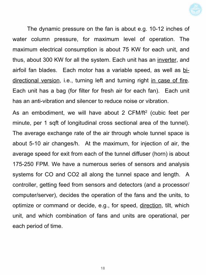
The dynamic pressure on the fan is about e.g. 10-12 inches of
water column pressure, for maximum level of operation. The
maximum electrical consumption is about 75 KW for each unit, and
thus, about 300 KW for all the system. Each unit has an inverter, and
airfoil fan blades. Each motor has a variable speed, as well as bi-
directional version, i.e., turning left and turning right in case of fire.
Each unit has a bag (for filter for fresh air for each fan). Each unit
has an anti-vibration and silencer to reduce noise or vibration.
As an embodiment, we will have about 2 CFM/ft2 (cubic feet per
minute, per 1 sqft of longitudinal cross sectional area of the tunnel).
The average exchange rate of the air through whole tunnel space is
about 5-10 air changes/h. At the maximum, for injection of air, the
average speed for exit from each of the tunnel diffuser (horn) is about
175-250 FPM. We have a numerous series of sensors and analysis
systems for CO and CO2 all along the tunnel space and length. A
controller, getting feed from sensors and detectors (and a processor/
computer/server), decides the operation of the fans and the units, to
optimize or command or decide, e.g., for speed, direction, tilt, which
unit, and which combination of fans and units are operational, per
each period of time.
18

This minimizes the pollution and particle concentrations in the
tunnel, depending on traffic and concentration. So, it is flexible,
dynamic, changeable, and optimized.
As an embodiment, we use the government mandate or
recommendations, e.g., EPA, UN, PIARC, ASHRAE, ISAVT, local
governments, and Federal rules and minimums or maximums, to
control the air flow and filtering.
For example, for heavy traffic, with length of time in tunnel for each
vehicle, in average, e.g., at 10-15 minutes, we set the maximum
allowable concentration for health purposes as 50-75 PPM (parts
per million) for all particles, as an example.
When fire happens inside tunnel, the units can reverse themselves,
for exhaust or suction, against fire effects.
As mentioned before, the Jet fan systems in use today uses about
e.g. 1000 or much more KW power, whereas our system uses 300
KW or more for the same tunnel, for injection method, which is
more than 3 times improvement on efficiency and savings in cost.
For a country with many tunnels, this can add up for millions of
dollars, as the extra high power towers and reducing to low power
stations (as the infrastructure for the tunnels, e.g., distribution
system or boxes or units) are also very expensive to install and
maintain.
19

In addition, much less cabling for power and control systems
within tunnel are needed with our system, which adds to cost
saving and differential or advantage for our system, for repair,
installation and operation.
Also, probably, the shaking and vibration cause the fans on ceiling
to get loose after a few years, without any or with low visible notice
or warning, causing dangerous or fatal crashes or accidents in the
tunnel, making our solution much safer, as it does not need such
preventive inspections or repairs, which are very disruptive or
dangerous for the traffic or repair crew. Note that our diffusers
have no mechanical parts, with no heavy fans or motors attached to
the ceilings.
20

ABSTRACT
In one example, we describe a method and system for Tunnel Air
Ventilation, which is very practical, economical, and easy to install
or implement. The repair and maintenance is safer and less
expensive. The overall cost of installation and repair is lower. The
system is more stable, and thus, safer for the vehicles and people.
It is not damaged by sand, and it does not cause damage to
vehicles by sand. So, the risk is minimized. The overall value for
the government and society is very high.
The efficiency and low down time translates to a cleaner air in the
tunnel, which is a major health issue for people, which causes
sickness and even death for pollution and toxicity, or by fatal
accidents in the tunnel, due to intoxication of the drivers or
dizziness. Different variations are also discussed and shown.
21

22
A preliminary longitudinal section which shows the base of new
system of tunnel ventilation.

23
Rendering sections of 3 types of air inlet horns for high, med and low
pollution areas of tunnel (inside).

24
Lower Part of the Duct’s Body
Rubber Gasket (Round)
Air Out (To Tunnel) Construction Detail of Horns
Air Intake
Aluminum Diffuser (Horn)
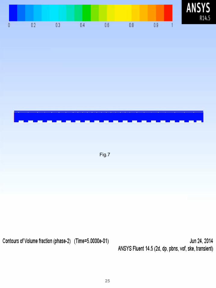
Fig.7
25

Contours of pressure compound formation
Fig.8
26

Contours of velocity one-way formation
Fig.9
27

Contours of Velocity All Down Formation
Fig.10
28

Contours of Velocity All Down Formation
Fig.11
29

Fig.12
30

Fig.13
31